MANUALE STAZIONE DI SERVIZIO - Guzzitek.org
MANUALE STAZIONE DI SERVIZIO - Guzzitek.org
MANUALE STAZIONE DI SERVIZIO - Guzzitek.org

Create successful ePaper yourself
Turn your PDF publications into a flip-book with our unique Google optimized e-Paper software.
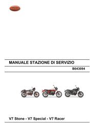
<strong>MANUALE</strong> <strong>STAZIONE</strong> <strong>DI</strong> <strong>SERVIZIO</strong><br />
V7 Stone - V7 Special - V7 Racer<br />
B043094
<strong>MANUALE</strong><br />
<strong>STAZIONE</strong> <strong>DI</strong><br />
<strong>SERVIZIO</strong><br />
V7 Stone - V7 Special - V7 Racer<br />
THE VALUE OF SERVICE<br />
As a result of continuous updates and specific technical training programmes for Moto Guzzi products,<br />
only Moto Guzzi Official Network mechanics know this vehicle fully and have the specific tools<br />
necessary to carry out maintenance and repair operations correctly.<br />
The reliability of the vehicle also depends on its mechanical conditions. Checking the vehicle before riding<br />
it, its regular maintenance and the use of original Moto Guzzi spare parts only are essential factors!<br />
For information on the nearest Official Dealer and/or Service Centre consult our website:<br />
www.motoguzzi.com<br />
Only by requesting Moto Guzzi original spare parts can you be sure of purchasing products that were<br />
developed and tested during the actual vehicle design stage. All Moto Guzzi original spare parts undergo<br />
quality control procedures to guarantee reliability and durability.<br />
The descriptions and images in this publication are given for illustrative purposes only and are not binding.<br />
While the basic characteristics as described and illustrated in this booklet remain unchanged, Piaggio &<br />
C. S.p.A. reserves the right, at any time and without being required to update this publication beforehand,<br />
to make any changes to components, parts or accessories, which it considers necessary to improve the<br />
product or which are required for manufacturing or construction reasons.<br />
Not all versions/models shown in this publication are available in all countries. The availability of individual<br />
versions/models should be confirmed with the official Moto Guzzi sales network.<br />
The Moto Guzzi trademark is the property of Piaggio & C. S.p.A.<br />
© Copyright 2012 - Piaggio & C. S.p.A. All rights reserved. Reproduction of this publication in whole or<br />
in part is prohibited.<br />
Piaggio & C. S.p.A. Viale Rinaldo Piaggio, 25 - 56025 PONTEDERA (PI), Italy<br />
www.piaggio.com
<strong>MANUALE</strong> <strong>STAZIONE</strong> <strong>DI</strong><br />
<strong>SERVIZIO</strong><br />
V7 Stone - V7 Special - V7 Racer<br />
Questo manuale fornisce le informazioni principali per le procedure di normale intervento sul veicolo.<br />
Questa pubblicazione è indirizzata ai Concessionari Moto Guzzi e ai loro meccanici qualificati; molte<br />
nozioni sono state volutamente omesse, perché giudicate superflue. Non essendo possibile includere<br />
nozioni meccaniche complete in questa pubblicazione, le persone che utilizzano questo manuale devono<br />
essere in possesso sia di una preparazione meccanica di base, che di una conoscenza minima sulle<br />
procedure inerenti ai sistemi di riparazione dei motoveicoli. Senza queste conoscenze, la riparazione o<br />
il controllo del veicolo potrebbe essere inefficiente o pericolosa. Non essendo descritte dettagliatamente<br />
tutte le procedure per la riparazione, e il controllo del veicolo, bisogna adottare particolare attenzione al<br />
fine di evitare danni ai componenti e alle persone. Per offrire al cliente maggiore soddisfazione dall. uso<br />
del veicolo, Moto Guzzi s.p.a. si impegna a migliorare continuamente i propri prodotti e la relativa<br />
documentazione. Le principali modifiche tecniche e modifiche alle procedure per le riparazioni del veicolo<br />
vengono comunicate a tutti i Punti Vendita Moto Guzzi e alle Filiali nel Mondo. Tali modifiche verranno<br />
apportate, nelle edizioni successive di questo manuale. Nel caso di necessità o dubbi sulle procedure<br />
di riparazione e di controllo, interpellare il REPARTO ASSISTENZA Moto Guzzi, il quale sarà in grado<br />
di fornirvi qualsiasi informazione al riguardo, oltre a fornire eventuali comunicazioni su aggiornamenti e<br />
modifiche tecniche applicate al veicolo.<br />
NOTE Provides key information to make the procedure easier to understand and carry out.<br />
CAUTION Refers to specific procedures to carry out for preventing damages to the vehicle.<br />
WARNING Refers to specific procedures to carry out to prevent injuries to the repairer.<br />
Personal safety Failure to completely observe these instructions will result in serious risk of personal<br />
injury.<br />
Safeguarding the environment Sections marked with this symbol indicate the correct use of the vehicle<br />
to prevent damaging the environment.
Vehicle intactness The incomplete or non-observance of these regulations leads to the risk of serious<br />
damage to the vehicle and sometimes even the invalidity of the guarantee
INDEX OF TOPICS<br />
CHARACTERISTICS CHAR<br />
SPECIAL TOOLS S-TOOLS<br />
MAINTENANCE MAIN<br />
ELECTRICAL SYSTEM ELE SYS<br />
ENGINE FROM VEHICLE ENG VE<br />
POWER SUPPLY P SUPP<br />
SUSPENSIONS SUSP<br />
CHASSIS CHAS<br />
BODYWORK BODYW<br />
PRE-DELIVERY PRE DE
INDEX OF TOPICS<br />
CHARACTERISTICS CHAR
V7 Stone - V7 Special - V7 Racer Characteristics<br />
Rules<br />
Safety rules<br />
Carbon monoxide<br />
If you need to keep the engine running while working on the vehicle, please ensure that you do so in<br />
an open or very well ventilated area. Never let the engine run in an enclosed area. If you do work in an<br />
enclosed area, make sure to use a fume extraction system.<br />
CAUTION<br />
EXHAUST EMISSIONS CONTAIN CARBON MONOXIDE, A POISONOUS GAS WHICH CAN CAUSE<br />
LOSS OF CONSCIOUSNESS AND EVEN DEATH.<br />
Fuel<br />
CAUTION<br />
THE FUEL USED TO POWER INTERNAL COMBUSTION ENGINES IS HIGHLY FLAMMABLE AND<br />
MAY BE EXPLOSIVE UNDER CERTAIN CON<strong>DI</strong>TIONS. IT IS THEREFORE RECOMMENDED TO<br />
CARRY OUT REFUELLING AND MAINTENANCE PROCEDURES IN A VENTILATED AREA WITH<br />
THE ENGINE SWITCHED OFF. DO NOT SMOKE DURING REFUELLING OR NEAR FUEL VAPOUR.<br />
AVOID ANY CONTACT WITH NAKED FLAME, SPARKS OR OTHER HEAT SOURCES WHICH MAY<br />
CAUSE IGNITION OR EXPLOSION.<br />
DO NOT ALLOW FUEL TO <strong>DI</strong>SPERSE INTO THE ENVIRONMENT.<br />
KEEP OUT OF THE REACH OF CHILDREN.<br />
Hot components<br />
The engine and the exhaust system components become very hot and remain hot for some time after<br />
the engine has been switched off. Before handling these components, make sure that you are wearing<br />
insulating gloves or wait until the engine and the exhaust system have cooled down.<br />
Used engine oil and transmission oil<br />
CAUTION<br />
IT IS ADVISABLE TO WEAR LATEX GLOVES WHEN SERVICING THE VEHICLE.<br />
THE ENGINE OR GEARBOX OIL MAY CAUSE SERIOUS INJURIES TO THE SKIN IF HANDLED<br />
FOR PROLONGED PERIODS OF TIME AND ON A REGULAR BASIS.<br />
WASH YOUR HANDS CAREFULLY AFTER HANDLING OIL.<br />
HAND THE OIL OVER TO OR HAVE IT COLLECTED BY THE NEAREST USED OIL RECYCLING<br />
COMPANY OR THE SUPPLIER.<br />
DO NOT <strong>DI</strong>SPOSE OF OIL IN THE ENVIRONMENT<br />
KEEP OUT OF THE REACH OF CHILDREN.<br />
Brake and clutch fluid<br />
CHAR - 7
Characteristics V7 Stone - V7 Special - V7 Racer<br />
BRAKE AND CLUTCH FLUIDS CAN DAMAGE THE PLASTIC OR RUBBER PAINTED SURFACES.<br />
WHEN SERVICING THE BRAKING OR THE CLUTCH SYSTEM PROTECT THESE COMPONENTS<br />
WITH A CLEAN CLOTH. ALWAYS WEAR PROTECTIVE GOGGLES WHEN SERVICING THESE<br />
SYSTEMS. BRAKE AND CLUTCH FLUIDS ARE EXTREMELY HARMFUL FOR YOUR EYES. IN<br />
THE EVENT OF ACCIDENTAL CONTACT WITH THE EYES, RINSE THEM IMME<strong>DI</strong>ATELY WITH<br />
PLENTY OF COLD, CLEAN WATER AND SEEK ME<strong>DI</strong>CAL ADVICE.<br />
KEEP OUT OF THE REACH OF CHILDREN.<br />
Battery electrolyte and hydrogen gas<br />
CAUTION<br />
THE BATTERY ELECTROLYTE IS TOXIC, CORROSIVE AND, AS IT CONTAINS SULPHURIC<br />
ACID, MAY CAUSE BURNING IF IT COMES INTO CONTACT WITH THE SKIN. WHEN HANDLING<br />
BATTERY ELECTROLYTE, WEAR TIGHT-FITTING GLOVES AND PROTECTIVE APPAREL. IN<br />
THE EVENT OF SKIN CONTACT WITH THE ELECTROLYTIC FLUID, RINSE WELL WITH PLENTY<br />
OF CLEAN WATER. IT IS PARTICULARLY IMPORTANT TO PROTECT YOUR EYES BECAUSE<br />
EVEN TINY AMOUNTS OF BATTERY ACID MAY CAUSE BLINDNESS. IN THE EVENT OF CON-<br />
TACT WITH THE EYES, RINSE WITH PLENTY OF WATER FOR FIFTEEN MINUTES AND CON-<br />
SULT AN EYE SPECIALIST IMME<strong>DI</strong>ATELY. IF THE FLUID IS ACCIDENTALLY SWALLOWED,<br />
DRINK LARGE QUANTITIES OF WATER OR MILK, FOLLOWED BY MILK OF MAGNESIA OR<br />
VEGETABLE OIL AND SEEK ME<strong>DI</strong>CAL ADVICE IMME<strong>DI</strong>ATELY. THE BATTERY RELEASES EX-<br />
PLOSIVE GASES; KEEP IT AWAY FROM FLAMES, SPARKS, CIGARETTES OR ANY OTHER<br />
HEAT SOURCES. ENSURE ADEQUATE VENTILATION WHEN SERVICING OR RECHARGING<br />
THE BATTERY.<br />
KEEP OUT OF THE REACH OF CHILDREN.<br />
BATTERY LIQUID IS CORROSIVE. DO NOT POUR IT OR SPILL IT, PARTICULARLY ON PLASTIC<br />
COMPONENTS. ENSURE THAT THE ELECTROLYTIC ACID IS COMPATIBLE WITH THE BAT-<br />
TERY BEING ACTIVATED.<br />
Maintenance rules<br />
GENERAL PRECAUTIONS AND INFORMATION<br />
When repairing, dismantling and reassembling the vehicle follow the recommendations reported below<br />
carefully.<br />
BEFORE REMOVING COMPONENTS<br />
• Before dismantling components, remove dirt, mud, dust and foreign bodies from the vehicle.<br />
Use the special tools designed for this bike, as required.<br />
COMPONENTS REMOVAL<br />
CHAR - 8<br />
• Do not loosen and/or tighten screws and nuts using pliers or any other tools than the specific<br />
wrench.<br />
• Mark the positions on all connection joints (pipes, cables, etc.) before separating them, and<br />
identify them with different distinctive symbols.<br />
• Each component needs to be clearly marked to enable identification during reassembly.<br />
• Clean and wash the dismantled components carefully using a low-flammability detergent.
V7 Stone - V7 Special - V7 Racer Characteristics<br />
• Keep mated parts together since they have "adjusted" to each other due to normal wear.<br />
• Some components must be used together or replaced altogether.<br />
• Keep away from heat sources.<br />
REASSEMBLY OF COMPONENTS<br />
CAUTION<br />
BEARINGS MUST BE ABLE TO ROTATE FREELY, WITHOUT JAMMING AND/OR NOISE: OTH-<br />
ERWISE, THEY NEED TO BE REPLACED.<br />
• Only use ORIGINAL Moto Guzzi SPARE PARTS.<br />
• Comply with lubricant and consumables use guidelines.<br />
• Lubricate parts (whenever possible) before reassembling them.<br />
• When tightening nuts and screws, start from the ones with the largest section or from the<br />
internal ones, moving diagonally. Tighten nuts and screws in successive steps before ap-<br />
plying the tightening torque.<br />
• Always replace self-locking nuts, washers, sealing rings, circlips, O-rings (OR), split pins<br />
and screws with new ones if their tread is damaged.<br />
• When assembling the bearings, make sure to lubricate them well.<br />
• Check that each component is assembled correctly.<br />
• After a repair or routine maintenance procedure, carry out pre-ride checks and test the ve-<br />
hicle on private grounds or in an area with low traffic density.<br />
• Clean all coupling surfaces, oil guard rims and gaskets before refitting them. Smear a light<br />
layer of lithium-based grease on the oil guard rims. Reassemble oil guards and bearings<br />
with the brand or lot number facing outward (visible side).<br />
ELECTRIC CONNECTORS<br />
Electric connectors must be disconnected as described below; failure to comply with this procedure<br />
causes irreparable damage to both the connector and the cable harness:<br />
Press the relevant safety hooks, if any.<br />
CAUTION<br />
• Grip the two connectors and disconnect them by pulling them in opposite directions.<br />
• If any signs of dirt, rust, moisture, etc. are noted, clean the inside of the connector carefully<br />
with a jet of compressed air.<br />
• Ensure that the cables are correctly fastened to the internal connector terminals.<br />
• Then connect the two connectors, ensuring that they couple correctly (if fitted with clips, you<br />
will hear them "click" into place).<br />
TO <strong>DI</strong>SCONNECT THE TWO CONNECTORS, DO NOT PULL THE CABLES.<br />
NOTE<br />
THE TWO CONNECTORS CONNECT ONLY FROM ONE SIDE: CONNECT THEM THE RIGHT WAY<br />
ROUND.<br />
TIGHTENING TORQUES<br />
CAUTION<br />
CHAR - 9
Characteristics V7 Stone - V7 Special - V7 Racer<br />
IN THE EVENT THAT A SELFBRAKING NUT IS UNSCREWED, IT IS NECESSARY TO REPLACE<br />
IT WITH A NEW ONE.<br />
CAUTION<br />
DO NOT FORGET THAT THE TIGHTENING TORQUES OF ALL FASTENING ELEMENTS ON<br />
WHEELS, BRAKES, WHEEL BOLTS AND ANY OTHER SUSPENSION COMPONENTS PLAY A<br />
KEY ROLE IN ENSURING VEHICLE SAFETY AND MUST COMPLY WITH SPECIFIED VALUES.<br />
CHECK THE TIGHTENING TORQUES OF FASTENING PARTS ON A REGULAR BASIS AND AL-<br />
WAYS USE A TORQUE WRENCH TO REASSEMBLE THESE COMPONENTS. FAILURE TO COM-<br />
PLY WITH THESE RECOMMENDATIONS MAY CAUSE ONE OF THESE COMPONENTS TO GET<br />
LOOSE AND EVEN DETACHED, THUS BLOCKING A WHEEL, OR OTHERWISE COMPROMISE<br />
VEHICLE HANDLING. THIS CAN LEAD TO FALLS, WITH THE RISK OF SERIOUS INJURY OR<br />
DEATH.<br />
Running-in<br />
Engine run-in is essential to ensure engine long life and correct operation. Twisty roads and gradients<br />
are ideal to run in engine, brakes and suspensions effectively. Vary your riding speed during the run-<br />
in. This ensures that components operate under both "loaded" and "unloaded" conditions, allowing the<br />
engine components to cool.<br />
CAUTION<br />
THE CLUTCH MAY EMIT A SLIGHT BURNING SMELL WHEN FIRST USED. THIS PHENOMENON<br />
SHOULD BE CONSIDERED NORMAL AND WILL <strong>DI</strong>SAPPEAR AS SOON AS THE CLUTCH <strong>DI</strong>SCS<br />
GET ADAPTED.<br />
IT IS IMPORTANT TO STRAIN ENGINE COMPONENTS DURING RUN-IN, HOWEVER, MAKE SURE<br />
NOT TO OVERDO THIS.<br />
CAUTION<br />
THE FULL PERFORMANCE OF THE VEHICLE IS ONLY AVAILABLE AFTER THE SERVICE AT<br />
THE END OF THE RUNNING IN PERIOD.<br />
Follow the guidelines detailed below:<br />
• Do not twist the throttle grip abruptly and completely when the engine is working at a low<br />
revs, either during or after run-in.<br />
• During the first 100 Km (62 miles) use the brakes gently, avoiding sudden or prolonged<br />
braking. That is to permit the adequate adjustment of the pad friction material to the brake<br />
discs.<br />
AFTER THE SPECIFIED MILEAGE, TAKE THE VEHICLE TO AN OFFICIAL Moto Guzzi DEALER<br />
FOR THE CHECKS IN<strong>DI</strong>CATED IN THE "AFTER RUN-IN" TABLE IN THE SCHEDULED MAINTE-<br />
NANCE SECTION TO AVOID INJURING YOURSELF, OTHERS AND /OR DAMAGING THE VEHI-<br />
CLE.<br />
Vehicle identification<br />
SERIAL NUMBER LOCATION<br />
These numbers are necessary for vehicle registration.<br />
NOTE<br />
ALTERING IDENTIFICATION NUMBERS MAY BE SERIOUSLY PUNISHABLE BY LAW. IN PAR-<br />
TICULAR, MO<strong>DI</strong>FYING THE CHASSIS NUMBER IMME<strong>DI</strong>ATELY VOIDS THE WARRANTY.<br />
CHAR - 10
V7 Stone - V7 Special - V7 Racer Characteristics<br />
This number consists of numbers and letters, as in<br />
the example shown below.<br />
ZGULWE0012MXXXXXX<br />
KEY:<br />
ZGU: WMI (World manufacturer identifier) code;<br />
LW: model;<br />
E00 (V7 Stone), G00 (V7 Special), H00 (V7 Rac-<br />
er): versions;<br />
0: free digit<br />
12: variable year of manufacture (12 - for 2012)<br />
M: production plant (M= Mandello del Lario);<br />
XXXXXX: serial number (6 digits);<br />
CHASSIS NUMBER<br />
The chassis number is stamped on the right hand<br />
side of the headstock.<br />
ENGINE NUMBER<br />
The engine number is stamped on the left side,<br />
close to the engine oil level check cap.<br />
Dimensions and mass<br />
Engine<br />
WEIGHT AND <strong>DI</strong>MENSIONS<br />
Specification Desc./Quantity<br />
Max. length 2185 mm (86 in)<br />
Max. width - V7 Special / V7 Stone 800 mm (31.5 in)<br />
Max. width - V7 Racer 730 mm (28.74 in)<br />
Max. height 1115 mm (43.9 in)<br />
Saddle height 805 mm (31.69 in)<br />
Wheelbase 1435 mm (56.5 in)<br />
Minimum ground clearance 182 mm (7.16 in)<br />
Kerb weight 198 kg (436 lb)<br />
ENGINE<br />
Specification Desc./Quantity<br />
Type traverse-mounted twin-cylinder four-stroke V 90°<br />
No. of cylinders 2<br />
CHAR - 11
Characteristics V7 Stone - V7 Special - V7 Racer<br />
Transmission<br />
Capacities<br />
Electrical system<br />
CHAR - 12<br />
Specification Desc./Quantity<br />
Engine capacity 744 cm³ (45.40 cu.in)<br />
Bore / stroke 80x74 mm (3.14x2.91 in)<br />
Compression ratio 10.4 : 1<br />
Electric Electric starter<br />
Engine idle speed 1350 +/- 100 rpm<br />
Intake valve clearance 0.15 mm (0.0059 in)<br />
Exhaust valve clearance 0.20 mm (0.0079 in)<br />
Clutch dry single-disc clutch with flexible coupling<br />
Lubrication Pressure-fed, controlled by valves and trochoidal pump<br />
Air filter cartridge-type dry filter<br />
Cooling air<br />
TRANSMISSION<br />
Specification Desc./Quantity<br />
Gearbox / Type mechanical, 5 speeds with foot lever on the left-hand side of<br />
the engine.<br />
Primary drive with gears, ratio: 16 / 21 = 1 : 1.3125<br />
Gear ratios, 1st gear 11 / 26 = 1 : 2.3636<br />
Gear ratios, 2nd gear 14 / 23 = 1 : 1.6429<br />
Gear ratios, 3rd gear 18 / 23 = 1 : 1.2778<br />
Gear ratios, 4th gear 18 / 19 = 1 : 1.0556<br />
Gear ratios, 5th gear 22 / 25 = 1 : 0.9<br />
Final drive with cardan shaft, ratio: 8 / 33 = 1 : 4.825<br />
CAPACITY<br />
Specification Desc./Quantity<br />
Fuel tank (reserve included) 21 l (4.62 UKgal; 5.55 US gal)<br />
Fuel tank reserve 4 l (0.88 UKgal; 1.06 US gal)<br />
Engine oil Oil change and oil filter replacement: 2000 cm³ (122.05 cu.in)<br />
Gearbox oil 1 l (0.26 USgal)<br />
Transmission oil 170 cm³ (10.37 cu.in)<br />
Seats - V7 Special / V7 Stone 2<br />
Seats - V7 Racer 1 + 1*<br />
Maximum carrying load 203 kg (447 lb) (rider + passenger + luggage)<br />
* 2 seats, if vehicle is fitted with long two-seater saddle, passenger<br />
footpegs, passenger grab handles (necessitating rear<br />
shock absorbers to be installed upside-down) and exhaust<br />
mounts.<br />
In this case, the user is responsible for finding out the correct<br />
procedures for revising the vehicle's road registration documentation<br />
from the relevant local authorities.<br />
ELECTRICAL SYSTEM<br />
Specification Desc./Quantity<br />
Battery 12V - 12 Ah<br />
Fuses 5 (2) - 10 - 15 (2) - 30 A<br />
Generator (alternator + rectifier) 12V - 350 W<br />
SPARK PLUGS<br />
Specification Desc./Quantity<br />
Standard NGK CPR8EB-9
V7 Stone - V7 Special - V7 Racer Characteristics<br />
Specification Desc./Quantity<br />
Alternatively: CHAMPION RG6YC<br />
Spark plug electrode gap 0.6 - 0.7 mm (0.024 - 0.027 in)<br />
Resistance 5 kOhm<br />
BULBS<br />
Specification Desc./Quantity<br />
Low/high beam light (halogen) 12 V - 55 W / 60 W H4<br />
Front daylight running light 12V - 5W<br />
Turn indicator light 12 V - 10 W (orange RY 10 W bulb)<br />
tail light /stop lights 12 V - 5 / 21 W<br />
Dashboard lighting LED<br />
WARNING LIGHTS<br />
Specification Desc./Quantity<br />
Gear in neutral LED<br />
Turn indicators LED<br />
Fuel reserve LED<br />
High beam light LED<br />
Engine oil pressure LED<br />
Injection check warning light LED<br />
Frame and suspensions<br />
CHASSIS<br />
Specification Desc./Quantity<br />
Type Modular double cradle, high strength steel tubular chassis<br />
Steering rake 27.5°<br />
Trail 138 mm (5.43 in)<br />
SUSPENSIONS<br />
Specification Desc./Quantity<br />
Front hydraulic telescopic fork, Ø 40 mm (1.57 in)<br />
Travel 130 mm (5.12 in)<br />
Rear - V7 Special / V7 Stone swinging arm in die-cast light alloy, 2 shock absorbers with adjustable<br />
spring preloading<br />
Rear - V7 Racer die-cast light alloy swingarm with 2 adjustable shock absorbers<br />
Wheel travel 100 mm (3.93 in)<br />
SIZES A AND B<br />
Specification Desc./Quantity<br />
Size A 692 mm (27.24 in)<br />
Size B 186 mm (7.32 in)<br />
CHAR - 13
Characteristics V7 Stone - V7 Special - V7 Racer<br />
Brakes<br />
Wheels and tyres<br />
Supply<br />
BRAKES<br />
Specification Desc./Quantity<br />
Front stainless steel floating disc, Ø 320 mm (12.59 in), callipers with<br />
4 different and counteracting plungers<br />
Rear 260 mm (10.24 in) stainless steel disc, floating calliper with two<br />
25.4 mm (1.00 in) diam. pistons<br />
WHEEL RIMS<br />
Specification Desc./Quantity<br />
Type - V7 Stone Alloy wheels for tubeless tyres<br />
Type - V7 Special / V7 Racer with spokes, for tyres with inner tubes<br />
Front 2.5''x18''<br />
Rear 3.50 x 17''<br />
TYRES<br />
Specification Desc./Quantity<br />
Front tyre PIRELLI SPORT DEMON<br />
Front (size) 100 / 90 - 18 56H TL<br />
Front (inflation pressure) 2.5 bar (250 kPa) (36.3 PSI)<br />
Front (inflation pressure with passenger) 2.6 bar (260 kPa) (37.71 PSI)<br />
Rear tyre PIRELLI SPORT DEMON<br />
Rear (size) 130 / 80 - 17 65H TL<br />
Rear (inflation pressure) 2.5 bar (250 kPa) (36.3 PSI)<br />
Rear (inflation pressure with passenger) 2.6 bar (260 kPa) (37.71 PSI)<br />
Tightening Torques<br />
Chassis<br />
CHAR - 14<br />
FUEL SYSTEM<br />
Specification Desc./Quantity<br />
Type Electronic injection (Marelli MIU G3)<br />
Venturi Ø 38 mm (1.50 in)<br />
Fuel Premium unleaded petrol, minimum octane rating of 95<br />
(NORM) and 85 (NOMM)
V7 Stone - V7 Special - V7 Racer Characteristics<br />
Front side<br />
FRONT SUSPENSION - STEERING<br />
pos. Description Type Quantity Torque Notes<br />
1 Stanchion cap - 2 50 Nm (36.88 lbf ft) -<br />
2 Screw fixing wheel axle to right fork leg M6x30 2 10 Nm (7.37 lbf ft) Tighten using a 1-2-1 sequence<br />
3 Screw fixing stanchions to upper and lower<br />
plate<br />
M10x40 4 50 Nm (36.88 lbf ft) -<br />
4 Headstock ring nut M25x1 1 7 Nm (5.16 lbf ft) The fork must fall to one<br />
side by itself<br />
CHAR - 15
Characteristics V7 Stone - V7 Special - V7 Racer<br />
pos. Description Type Quantity Torque Notes<br />
5 Headstock bushing M23x1 1 50 Nm (36.88 lbf ft) -<br />
INSTRUMENT PANEL<br />
pos. Description Type Quantity Torque Notes<br />
1 Screw fixing instrument panel to headlamp support<br />
M6x10 3 10 Nm (7.37 lbf ft) -<br />
(V7 SPECIAL / V7 STONE)<br />
CHAR - 16
V7 Stone - V7 Special - V7 Racer Characteristics<br />
HANDLEBAR AND CONTROLS<br />
Pos. Description Type Quantity Torque Notes<br />
1 Switch fastener screw SWP 5 1+1 1.5 Nm (1.11 lb ft) -<br />
2 Counterweight fixing screw M6 2 10 Nm (7.37 lb ft) Loctite 243<br />
3 Screw fastening the clutch control U-bolt to<br />
the semi-handlebar<br />
M6x25 2 10 Nm (7.37 lb ft) -<br />
(V7 RACER)<br />
HANDLEBAR AND CONTROLS<br />
Pos. Description Type Quantity Torque Notes<br />
1 Switch fastener screw M5 1+1 1.5 Nm (1.11 lb ft) Tighten using a 1-2-1 sequence<br />
2 Semi-handlebar fixing screw M6x25 4 10 Nm (7.37 lb ft) Tighten using a 1-2-1 sequence<br />
3 Counterweight fixing screw M6 2 10 Nm (7.37 lb ft) Loctite 243<br />
4 Screw fastening the clutch control U-bolt to<br />
the semi-handlebar<br />
M6x25 2 10 Nm (7.37 lb ft) Tighten using a 1-2-1 sequence<br />
CHAR - 17
Characteristics V7 Stone - V7 Special - V7 Racer<br />
FRONT BRAKE SYSTEM<br />
pos. Description Type Quantity Torque Notes<br />
1 Screw fastening the brake pump U-bolt to the<br />
semi-handlebar<br />
M6x25 2 10 Nm (7.37 lb ft) -<br />
2 Front brake calliper fixing screw M10x30 2 50 Nm (36.88 lb ft) -<br />
3 Drilled screw for brake fluid pipe on pump and<br />
calliper<br />
- 2 25 Nm (18.44 lb ft) -<br />
CHAR - 18
V7 Stone - V7 Special - V7 Racer Characteristics<br />
FRONT LIGHTS<br />
pos. Description Type Quantity Torque Notes<br />
1 Headlamp fixing screw M8x30 2 15 Nm (11.06 lb ft) -<br />
2 Front turn indicator fixing screw M6 2 5 Nm (3.69 lb ft) -<br />
3 Horn fixing screw M6x16 2 10 Nm (7.37 lb ft) -<br />
4 Headlamp support bracket fixing<br />
screw<br />
M10x40 2 50 Nm (36.88 lb ft) -<br />
BODYWORK - FRONT SECTION<br />
pos. Description Type Quantity Torque Notes<br />
1 Screw fastening stabiliser plate to fork M8x40 4 15 Nm (11.06 lbf ft) Loctite 243<br />
2 Screw fastening mudguard to stabiliser<br />
plate<br />
M6x11 4 10 Nm (7.37 lbf ft) Loctite 243<br />
3 Top fairing fixing screw M6 2 10 Nm (7.37 lbf ft)<br />
CHAR - 19
Characteristics V7 Stone - V7 Special - V7 Racer<br />
FRONT WHEEL<br />
pos. Description Type Quantity Torque Notes<br />
1 Front wheel axle M18x1.5 1 80 Nm (59.00 lbf ft) -<br />
2 Front brake disc fixing screw M8x20 6 25 Nm (18.44 lbf ft) Loctite 243<br />
Central part<br />
CHAR - 20
V7 Stone - V7 Special - V7 Racer Characteristics<br />
FRAME<br />
pos. Description Type Quantity Torque Notes<br />
1 Screw fixing tank mounting rubber<br />
blocks to frame<br />
M8x14 2 25 Nm (18.44 lbf ft) -<br />
2 Cradle front fixing screw M10x30 4 50 Nm (36.88 lbf ft) -<br />
3 Screw fastening gearbox to frame M10x55 2 50 Nm (36.88 lbf ft) -<br />
4 Pin fixing engine/gearbox to chassis M10x205 1 50 Nm (36.88 lbf ft) -<br />
5 Screw fixing exhaust silencer mounting<br />
to frame<br />
M8x16 4 25 Nm (18.44 lbf ft) Loctite 243<br />
6 Battery supporting plate fixing screw M8x16 4 25 Nm (18.44 lbf ft) -<br />
FRAME CRADLES<br />
pos. Description Type Quantity Torque Notes<br />
1 Screw fixing stand beam to cradle M10x260 1 50 Nm (36.88 lbf ft) -<br />
2 Screw fixing stand beam to cradle M8 1+1 25 Nm (18.44 lbf ft) -<br />
3 Pin fixing engine/gearbox to chassis M10x250 1 50 Nm (36.88 lbf ft) -<br />
4 Screw fastening cradle to frame M10x65 2 50 Nm (36.88 lbf ft) -<br />
(V7 SPECIAL / V7 STONE)<br />
CHAR - 21
Characteristics V7 Stone - V7 Special - V7 Racer<br />
DRIVER FOOTRESTS<br />
pos. Description Type Quantity Torque Notes<br />
1 Pedal rubber fastening screw M6x12 4 10 Nm (7.38 lb ft) -<br />
2 Screw fastening rider footrest mounting to<br />
frame<br />
M8 2+2 25 Nm (18.44 lb ft) Loct. 243<br />
(V7 RACER)<br />
RIDER FOOTREST / GEAR SHIFT LEVER<br />
pos. Description Type Quantity Torque Notes<br />
1 Screw fastening left hand rider footrest<br />
mounting plate to cradle<br />
M8x20 2 25 Nm (18.44 lb ft) Loctite 243<br />
CHAR - 22
V7 Stone - V7 Special - V7 Racer Characteristics<br />
pos. Description Type Quantity Torque Notes<br />
2 Preselector lever fixing screw M6x20 1 10 Nm (7.37 lb ft) -<br />
3 Gearbox lever fixing screws M6x20 1 10 Nm (7.37 lb ft) Loctite 243<br />
4 Gearbox control rod fixing nut M6x1 1 10 Nm (7.37 lb ft) -<br />
5 Screw fastening rider footrest mounting<br />
to plate<br />
M8 1 20 Nm (14.75 lb ft) Loctite 243<br />
(V7 RACER)<br />
RIDER FOOTREST / REAR BRAKE LEVER<br />
pos. Description Type Quantity Torque Notes<br />
1 Screw fastening right hand rider footrest<br />
mounting plate to cradle<br />
M8x20 2 20 Nm (14.75 lb ft) Loctite 243<br />
2 Rear brake lever fixing screw M6x20 1 10 Nm (7.37 lb ft) Loctite 243<br />
3 Screw fastening rider footrest mounting<br />
to plate<br />
M8 1 25 Nm (18.44 lb ft) Loctite 243<br />
4 Rear brake pump fixing screw M6x25 2 8 Nm (5.90 lb ft) Loctite 243<br />
5 Rear brake fluid reservoir fixing<br />
screw<br />
M5x15 1 6 Nm (4.43 lb ft) -<br />
6 Nut fastening rod terminal on brake<br />
lever<br />
M6 1 10 Nm (7.37 lb ft) -<br />
CHAR - 23
Characteristics V7 Stone - V7 Special - V7 Racer<br />
SIDE STAND<br />
pos. Description Type Quantity Torque Notes<br />
1 Side stand retainer pin M10x1.2<br />
5<br />
1 10 Nm (7.38 lb ft) -<br />
2 Lock nut for stand bolt M10x1.2<br />
5<br />
1 30 Nm (22.13 lb ft) -<br />
3 Switch fixing screw M5x16 2 6 Nm (4.42 lb ft) -<br />
(V7 RACER)<br />
(V7 SPECIAL / V7 STONE)<br />
CHAR - 24
V7 Stone - V7 Special - V7 Racer Characteristics<br />
FUEL TANK<br />
pos. Description Type Quantity Torque Notes<br />
1 Rear tank fixing screw M8x45 1 25 Nm (18.44 lb ft) -<br />
2 Screw fastening cap flange to tank M5x12 2+3 4 Nm (2.95 lb ft) -<br />
FUEL SUPPLY SYSTEM<br />
pos. Description Type Quantity Torque Notes<br />
1 Screw fixing fuel pump mounting to<br />
tank<br />
M5x16 6 6 Nm (4.43 lbf ft) -<br />
CHAR - 25
Characteristics V7 Stone - V7 Special - V7 Racer<br />
TIGHTENING TORQUE - CENTRAL PART - FILTER BOX<br />
pos. Description Type Quantity Torque Notes<br />
1 Air filter box cover fastening screw SWP 5x14 4 3 Nm (2.21 lb ft) -<br />
2 Air filter box fastening screw to frame SWP 5x20 2 3 Nm (2.21 lb ft) -<br />
3 Air filter box fastening screw SWP 5x20 9 3 Nm (2.21 lb ft) -<br />
(V7 SPECIAL / V7 STONE)<br />
CHAR - 26
V7 Stone - V7 Special - V7 Racer Characteristics<br />
BODYWORK CENTRAL SECTION - SADDLE<br />
pos. Description Type Quantity Torque Notes<br />
1 Saddle release block fixing screw M6x25 2 10 Nm (2.37 lb ft) -<br />
2 Side fairing fixing screw M5x9 2 4 Nm (2.95 lb ft) -<br />
(V7 RACER)<br />
BODYWORK CENTRAL SECTION - SADDLE<br />
pos. Description Type Quantity Torque Notes<br />
1 Saddle release block fixing screw M6x25 2 10 Nm (2.37 lb ft) -<br />
2 Throttle body cover fastener screw M5x14 4 4 Nm (2.95 lb ft) -<br />
3 Side fairing fixing screw M5x9 6 4 Nm (2.95 lb ft) -<br />
CHAR - 27
Characteristics V7 Stone - V7 Special - V7 Racer<br />
LOCK KIT<br />
pos. Description Type Quantity Torque Notes<br />
1 (Shear head) screw fixing ignition<br />
lock<br />
M8x15 1 - At the point of failure<br />
2 Ignition lock fixing screw M8x16 1 25 Nm (18.44 lb ft) -<br />
CHAR - 28
V7 Stone - V7 Special - V7 Racer Characteristics<br />
EXHAUST SYSTEM<br />
Pos. Description Type Quantity Torque Notes<br />
1 Exhaust pipe fixing nut to the engine M6 4 10 Nm (7.37 lb ft) -<br />
2 Exhaust pipe fixing clamp screw to<br />
the compensator<br />
M6 1+1 10 Nm (7.37 lb ft) -<br />
3 Compensator fixing clamp screw to<br />
the silencer<br />
M6 2 10 Nm (7.37 lb ft) -<br />
4 Lambda probe on compensator M18x1.5 1 38 Nm (28.03 lb ft) -<br />
5 Nut fastening silencer to mounting<br />
plate<br />
M8 4 25 Nm (18.44 lb ft) -<br />
6 Heat shield fixing screw M6x12 6 10 Nm (7.37 lb ft) Loctite 270<br />
7 Screw fixing silencer mounting plate<br />
to frame<br />
M8x40 2 25 Nm (18.44 lb ft) -<br />
Back side<br />
REAR TRANSMISSION - SWINGARM<br />
pos. Description Type Quantity Torque Notes<br />
1 Swingarm clamp retaining screw M10x45 1 30 Nm (22.13 lbf ft) -<br />
2 Pin fixing the rear calliper holding<br />
plate to swingarm<br />
M16x1 1 25 Nm (18.44 lbf ft) -<br />
3 Nut fixing gearcase to swingarm M8 4 25 Nm (18.44 lbf ft) Hold the stud bolt<br />
4 Pin fixing swingarm to gearbox M20x1 2 - Fully home with no<br />
preload<br />
5 Lock nut on swingarm pin M20x1 2 50 Nm (36.88 lbf ft) Hold the pin<br />
(V7 SPECIAL / V7 STONE)<br />
CHAR - 29
Characteristics V7 Stone - V7 Special - V7 Racer<br />
(V7 RACER)<br />
REAR SUSPENSION<br />
pos. Description Type Quantity Torque Notes<br />
1 Upper screw fastening shock absorber to<br />
frame<br />
M6x35 2 10 Nm (7.37 lbf ft) Loctite 243<br />
2 Lower pin fastening left shock absorber to<br />
swingarm<br />
M10x1.5 1 35 Nm (25.81 lbf ft)<br />
CHAR - 30
V7 Stone - V7 Special - V7 Racer Characteristics<br />
pos. Description Type Quantity Torque Notes<br />
3 Stud bolt fixing right shock absorber to rear<br />
box<br />
M12x1.5 1 35 Nm (25.81 lbf ft) -<br />
4 Screw fastening right shock absorber to stud<br />
bolt<br />
M6x16 1 10 Nm (7.37 lbf ft) Loctite 243<br />
(V7 SPECIAL / V7 STONE)<br />
PASSENGER FOOTRESTS<br />
pos. Description Type Quantity Torque Notes<br />
1 Pedal rubber fastening screw M6x12 4 10 Nm (7.38 lb ft) -<br />
2 Screw fastening passenger footrest mounting<br />
to frame<br />
M8 2+2 25 Nm (18.44 lb ft) Loct. 243<br />
CHAR - 31
Characteristics V7 Stone - V7 Special - V7 Racer<br />
REAR WHEEL<br />
pos. Description Type Quantity Torque Notes<br />
1 Rear wheel axle nut M16x1.5 1 120 Nm (88.51 lb ft) -<br />
2 Rear brake disc fixing screw M8x25 6 25 Nm (18.44 lb ft) Loctite 243<br />
REAR BRAKE SYSTEM<br />
pos. Description Type Quantity Torque Notes<br />
1 Rear brake calliper fixing screw M8x30 2 25 Nm (18.44 lb ft) -<br />
CHAR - 32
V7 Stone - V7 Special - V7 Racer Characteristics<br />
pos. Description Type Quantity Torque Notes<br />
2 Drilled screw for brake pipe on calliper<br />
- 1 25 Nm (18.44 lb ft) -<br />
REAR LIGHTS<br />
pos. Description Type Quantity Torque Notes<br />
1 Screw fastening taillight support to<br />
mudguard<br />
M5x14 3 4 Nm (2.95 lbf ft) -<br />
2 Rear turn indicator fixing screw M6 2 5 Nm (3.69 lbf ft) -<br />
(V7 RACER)<br />
CHAR - 33
Characteristics V7 Stone - V7 Special - V7 Racer<br />
REAR SECTION BODYWORK - LICENSE PLATE MOUNTING<br />
pos. Description Type Quantity Torque Notes<br />
1 Screw fastening retroreflector mounting to license<br />
plate mounting<br />
M5x10 2 4 Nm (2.95 lbf ft) -<br />
2 Nut fixing retroreflector to mounting M5 1 4 Nm (2.95 lbf ft) -<br />
CHAR - 34
V7 Stone - V7 Special - V7 Racer Characteristics<br />
REAR MUDGUARD<br />
pos. Description Type Quantity Torque Notes<br />
1 Rear mudguard front and central fixing screw M6 2+1 10 Nm (7.37 lb ft)<br />
2 Rear mudguard side fixing screw M8x30 2 25 Nm (18.44 lb ft)<br />
3 Screw fixing license plate holder to mudguard<br />
reinforcement<br />
SWP<br />
M5x20<br />
ELECTRICAL SYSTEM 01<br />
3 3 Nm (2.21 lb ft)<br />
pos. Description Type Quantity Torque Notes<br />
1 Speed sensor fastening screw M6 1 10 Nm (7.37 lb ft)<br />
2 Fuse box bracket fixing screw M5x12 2 4 Nm (2.95 lb ft) -<br />
3 Battery holder bracket fastening screw M6 2 Manual -<br />
CHAR - 35
Characteristics V7 Stone - V7 Special - V7 Racer<br />
ELECTRICAL SYSTEM 02<br />
pos. Description Type Quantity Torque Notes<br />
1 1 - Coil fixing nut M6 2+2 10 Nm (7.37 lb ft) -<br />
2 2 - Timing sensor fastener screw - 1 .. Nm (... lb ft) -<br />
Recommended products chart<br />
NOTE<br />
RECOMMENDED PRODUCTS TABLE<br />
Product Description Specifications<br />
ENI i-RIDE PG 10W-60 Lubricant formulated with advanced synthetic<br />
technology and high performance<br />
additives to cater specifically for 4-stroke<br />
engines with high specific power outputs.<br />
JASO MA, MA2 - API SG<br />
AGIP GEAR MG SAE 85W-140 Transmission oil API GL-4 and GL-5<br />
AGIP GEAR MG/S SAE 85 W-90 Gearbox oil API GL-5<br />
AGIP FORK 7.5W Fork oil SAE 5W / SAE 20W<br />
AGIP GREASE SM 2 Gray black smooth-textured lithium<br />
grease, containing molybdenum disulphide.<br />
-<br />
Neutral grease or petroleum jelly. BATTERY POLES<br />
AGIP BRAKE 4 Brake fluid SAE J 1703 -FMVSS 116 - DOT 3/4 - ISO<br />
4925 - CUNA NC 956 DOT 4 synthetic<br />
fluid<br />
USE ONLY NEW BRAKE FLUID. DO NOT MIX <strong>DI</strong>FFERENT BRANDS OR TYPES OF OIL WITHOUT<br />
CHECKING THEIR BASE COMPATIBILITY.<br />
CHAR - 36
INDEX OF TOPICS<br />
SPECIAL TOOLS S-TOOLS
Special tools V7 Stone - V7 Special - V7 Racer<br />
S-TOOLS - 38<br />
SPECIAL TOOLS<br />
Stores code Description<br />
19.92.61.00 Punch for seal ring of bevel gear set pinion<br />
19.92.88.00 Bevel gear set alignment pre-fitting tool<br />
19.92.60.00 Punch for gearcase sealing ring<br />
19.90.70.00 Extractor for internal ring on drilled bolt<br />
19.92.75.00 Extractor for external ring of gearcase<br />
bearing<br />
19.92.62.00 Punch for bearing on bevel gear set pinion
V7 Stone - V7 Special - V7 Racer Special tools<br />
Stores code Description<br />
19.92.64.00 Punch for external ring of tapered bearing<br />
on bevel gear set pinion holding body<br />
19.92.65.00 Punch for external ring of gearcase bearing<br />
19.92.76.00 Extractor for swinging arm holder bearing<br />
on gearbox cover<br />
S-TOOLS - 39
INDEX OF TOPICS<br />
MAINTENANCE MAIN
V7 Stone - V7 Special - V7 Racer Maintenance<br />
Maintenance chart<br />
NOTE<br />
CARRY OUT MAINTENANCE OPERATIONS AT HALF THE INTERVALS SPECIFIED IF THE VE-<br />
HICLE IS USED IN PARTICULAR RAINY OR DUSTY CON<strong>DI</strong>TIONS, OFF ROAD OR FOR TRACK<br />
USE.<br />
NOTE<br />
THE TIMES LISTED ON THE SCHEDULED MAINTENANCE TABLE INCLUDE TIME DE<strong>DI</strong>CATED<br />
TO MANAGEMENT ACTIVITIES.<br />
I: INSPECT AND CLEAN, ADJUST, LUBRICATE OR REPLACE IF NECESSARY<br />
V: CHECK AND CLEAN, ADJUST AND REPLACE IF NECESSARY<br />
C: CLEAN, R: REPLACE, A: ADJUST, L: LUBRICATE<br />
(1) Replace in case of leaks.<br />
(2) Replace every 2 years or 20000 Km (12427 mi).<br />
(3) Replace every 4 years.<br />
(4) At each engine start.<br />
(5) Check every month.<br />
(6) Check every 3,000 km (1,864 mi)<br />
(7) Check and clean and adjust or replace, if necessary, every 1,000 Km (621 mi)<br />
ROUTINE MAINTENANCE TABLE<br />
km x 1,000 1 10 20 30 40 50 60<br />
Spark plugs R R R R R R<br />
Transmission cables and controls I I I I I I I<br />
Steering bearings and steering clearance I I I I I I I<br />
Wheel bearings I I I I I I<br />
Brake discs I I I I I I I<br />
Air filter R R R R R R<br />
Engine oil filter R R R R R R R<br />
Lights operation / aiming I I I I I I<br />
Vehicle general operation I I I I I I I<br />
Braking systems I I I I I I I<br />
Light circuit I I I I I I I<br />
Safety switches I I I I I I I<br />
Brake fluid (2) I I I I I I I<br />
Gearbox oil R R R R<br />
Fork oil R R R<br />
Engine oil (6) R R R R R R R<br />
Final drive oil R R R R<br />
Fork oil seal (1) I I I I<br />
Tyres - pressure/wear (5) I I I I I I I<br />
Valve clearance adjustment A A A A A A A<br />
Wheels I I I I I I I<br />
Bolts and nuts tightening I I I I I I I<br />
Battery terminals tightening I<br />
Head screws tightening A<br />
Suspension and setting I I I I<br />
Engine oil pressure warning light (4)<br />
Fuel lines (3) I I I I I I<br />
Brake lines (3) I I I I I I<br />
Clutch wear I I I I I I<br />
Brake pad wear (7) V V V V V V V<br />
Labour time (minutes) 100 70 130 70 130 70 130<br />
MAIN - 41
Maintenance V7 Stone - V7 Special - V7 Racer<br />
Transmission fluid<br />
Check<br />
• Keep the vehicle upright with both wheels on the<br />
ground.<br />
• Unscrew and remove the cap/dipstick (1).<br />
• The level is correct if the oil is close to the hole<br />
of the cap/dipstick (1).<br />
• If the oil is lower than specified, top-up until it<br />
reaches the cap/dipstick hole (1).<br />
CAUTION<br />
DO NOT ADD AD<strong>DI</strong>TIVES OR ANY OTHER SUBSTANCE TO<br />
THE FLUID. WHEN USING A FUNNEL OR ANY OTHER EL-<br />
EMENT, MAKE SURE IT IS PERFECTLY CLEAN.<br />
Replacement<br />
CAUTION<br />
THE UNIT MUST BE HOT WHEN THE OIL IS CHANGED AS UNDER SUCH CON<strong>DI</strong>TIONS OIL IS<br />
FLUID AND THEREFORE EASY TO DRAIN.<br />
NOTE<br />
RIDE SOME km (miles) TO WARM UP ENGINE OIL<br />
CAUTION<br />
• Place a container with + 400 cm³ (25 cu in) capacity under the drainage plug (3).<br />
• Unscrew and remove the drainage plug (3).<br />
• Unscrew and remove the breather cap (2).<br />
• Drain the oil into the container; allow several minutes for oil to drain out completely.<br />
• Check and if necessary, replace the sealing washer of drainage plug (3).<br />
• Remove any metal scrap attached to the drainage plug (3) magnet.<br />
• Screw and tighten the drainage plug (3).<br />
• Pour new oil through the fill opening (1) until it reaches the cap/dipstick hole (1).<br />
DO NOT ADD AD<strong>DI</strong>TIVES OR ANY OTHER SUBSTANCE TO THE FLUID. WHEN USING A FUNNEL<br />
OR ANY OTHER ELEMENT, MAKE SURE IT IS PERFECTLY CLEAN.<br />
MAIN - 42
V7 Stone - V7 Special - V7 Racer Maintenance<br />
• Screw and tighten the caps (1 - 2).<br />
Engine oil<br />
Check<br />
CAUTION<br />
ENGINE MUST BE WARM TO CHECK ENGINE OIL LEVEL<br />
NOTE<br />
DO NOT LET THE ENGINE IDLE WITH THE VEHICLE AT STANDSTILL TO WARM UP THE ENGINE<br />
AND REACH THE OPERATING TEMPERATURE OF ENGINE OIL. OIL IS BEST CHECKED AFTER<br />
RUNNING FOR ABOUT 15 KM (10 miles).<br />
• Switch off the engine and wait at least five minutes to allow the lubricant to drain back into<br />
the sump.<br />
• Keep the vehicle upright with both wheels on the ground.<br />
• Unscrew and remove the cap with dipstick.<br />
• Clean dipstick.<br />
• Refit the cap with dipstick into its hole without tightening.<br />
• Remove the cap with dipstick.<br />
• Check oil level by means of the oil dipstick.<br />
• The oil level is correct when it close to the "MAX" mark.<br />
MAX = maximum level<br />
MIN = minimum level<br />
Add engine oil if required:<br />
• Unscrew and remove the cap with dipstick.<br />
• Top-up with engine oil until it goes above the minimum level marked "MIN".<br />
MAIN - 43
Maintenance V7 Stone - V7 Special - V7 Racer<br />
CAUTION<br />
DO NOT ADD AD<strong>DI</strong>TIVES OR ANY OTHER SUBSTANCE TO<br />
THE OIL. WHEN USING A FUNNEL OR ANY OTHER ELE-<br />
MENT, MAKE SURE IT IS PERFECTLY CLEAN.<br />
Replacement<br />
• Place a container with + 2000 cm³ (122<br />
cu.in) capacity under the drainage<br />
plugs (1).<br />
• Unscrew and remove the drainage<br />
plugs (1).<br />
• Unscrew and remove the filler cap (2).<br />
• Drain the oil into the container; allow<br />
several minutes for oil to drain out com-<br />
pletely.<br />
• Check and if necessary, replace the<br />
sealing washers of drainage plugs (1).<br />
• Remove any metal scrap attached to<br />
the magnet of drainage plugs (1).<br />
• Screw and tighten the drainage plugs<br />
(1).<br />
Drainage plugs tightening torque (1): 12 Nm<br />
(1.2 kgm)<br />
DO NOT <strong>DI</strong>SPOSE OF OIL INTO THE ENVIRONMENT.<br />
<strong>DI</strong>SPOSE OF ENGINE OIL IN A SEALED CONTAINER AND<br />
TAKE IT TO YOUR SUPPLIER OR TO THE NEAREST USED<br />
OIL COLLECTION CENTRE.<br />
MAIN - 44
V7 Stone - V7 Special - V7 Racer Maintenance<br />
Engine oil filter<br />
NOTE<br />
• Loosen the screw (3) and remove the<br />
cover (4).<br />
• Remove the engine oil filter (5).<br />
NEVER REUSE AN OLD FILTER.<br />
Air filter<br />
• Spread a thin layer of oil on the sealing ring (6) of the new engine oil filter.<br />
• Fit the new engine oil filter with the spring facing downwards.<br />
• Refit the cover (4), screw and tighten the screw (3)<br />
• Remove the saddle<br />
• Unhook the connector from the air-box cover<br />
• Remove the air-box cover fixing screw<br />
• Remove the air-box cover<br />
• Extract the air filter<br />
MAIN - 45
Maintenance V7 Stone - V7 Special - V7 Racer<br />
Throttle body removal<br />
MAIN - 46<br />
• Loosen the clamps that secure the<br />
sleeve to the intake manifolds<br />
• Remove the sleeve<br />
• Remove the battery<br />
• Remove the MIU G3 control unit con-<br />
nector support bracket fixing screw
V7 Stone - V7 Special - V7 Racer Maintenance<br />
• Disconnect the MIU G3 control unit<br />
connector<br />
• Unscrew the clamp that secures the<br />
throttle body to the filter box<br />
• Extract the throttle body laterally<br />
• Remove the throttle body guard<br />
• Loosen the gas cables fixing nuts on<br />
the throttle body and unhook them<br />
MAIN - 47
Maintenance V7 Stone - V7 Special - V7 Racer<br />
• Remove the throttle body<br />
Throttle body installation<br />
MAIN - 48<br />
• Connect the gas cables on the throttle<br />
body<br />
• Correctly position the guides and tight-<br />
en the nuts, checking correct operation<br />
of the throttle grip<br />
• Install the throttle body guard
V7 Stone - V7 Special - V7 Racer Maintenance<br />
CAUTION<br />
• Insert the throttle body in the sleeve<br />
and tighten the clamp to secure it<br />
TAKE PARTICULAR CARE THAT THE CLAMP IS POSI-<br />
TIONED CORRECTLY. INCORRECT POSITIONING WILL<br />
CAUSE VEHICLE MALFUNCTIONS<br />
• Connect the MIU G3 control unit con-<br />
nector<br />
• Install the MIU G3 control unit connec-<br />
tor support bracket<br />
• Install the sleeve, taking care that they<br />
are inserted correctly<br />
MAIN - 49
Maintenance V7 Stone - V7 Special - V7 Racer<br />
• Tighten the clamps, checking correct<br />
positioning<br />
Air filter housing<br />
FRAME<br />
pos. Description Type Quantity Torque Notes<br />
1 Screw fixing tank mounting rubber<br />
blocks to frame<br />
M8x14 2 25 Nm (18.44 lbf ft) -<br />
2 Cradle front fixing screw M10x30 4 50 Nm (36.88 lbf ft) -<br />
MAIN - 50
V7 Stone - V7 Special - V7 Racer Maintenance<br />
pos. Description Type Quantity Torque Notes<br />
3 Screw fastening gearbox to frame M10x55 2 50 Nm (36.88 lbf ft) -<br />
4 Pin fixing engine/gearbox to chassis M10x205 1 50 Nm (36.88 lbf ft) -<br />
5 Screw fixing exhaust silencer mounting<br />
to frame<br />
M8x16 4 25 Nm (18.44 lbf ft) Loctite 243<br />
6 Battery supporting plate fixing screw M8x16 4 25 Nm (18.44 lbf ft) -<br />
TIGHTENING TORQUE - CENTRAL PART - FILTER BOX<br />
pos. Description Type Quantity Torque Notes<br />
1 Air filter box cover fastening screw SWP 5x14 4 3 Nm (2.21 lb ft) -<br />
2 Air filter box fastening screw to frame SWP 5x20 2 3 Nm (2.21 lb ft) -<br />
3 Air filter box fastening screw SWP 5x20 9 3 Nm (2.21 lb ft) -<br />
Air filter housing removal<br />
• Remove the saddle and the side fair-<br />
ings<br />
• Remove the battery<br />
• Remove the rear wheel.<br />
• Remove the splash guard<br />
• Remove the fuse box support fixing<br />
screws (1)<br />
MAIN - 51
Maintenance V7 Stone - V7 Special - V7 Racer<br />
See also<br />
• Move the filter box to the side enough<br />
to allow removal of the fixing screws (2)<br />
on the left side of the filter box support.<br />
Side body panels<br />
Splash guard<br />
Removing<br />
Specific operations for the vehicle<br />
MAIN - 52<br />
• Move the filter box to the side enough<br />
to allow removal of the fixing screws (3)<br />
on the right side of the filter box sup-<br />
port.<br />
• Disconnect the neutral switch connec-<br />
tor<br />
• Lift the air filter box enough to allow the<br />
support plate to be removed, sliding<br />
out neutral switch cabling
V7 Stone - V7 Special - V7 Racer Maintenance<br />
• Unscrew the clamp that fastens the<br />
throttle body to the air filter box<br />
• Disconnect the blow-by and breather<br />
tubes<br />
• Remove the air-box cover<br />
• Remove sliding the complete filter box<br />
out toward the rear<br />
MAIN - 53
Maintenance V7 Stone - V7 Special - V7 Racer<br />
Air filter housing installation<br />
CAUTION<br />
• Insert the filter box from the rear<br />
• Insert the throttle body in the sleeve<br />
and tighten the clamp to secure it<br />
TAKE PARTICULAR CARE THAT THE CLAMP IS POSI-<br />
TIONED CORRECTLY. INCORRECT POSITIONING WILL<br />
CAUSE VEHICLE MALFUNCTIONS<br />
MAIN - 54<br />
• Install the air-box cover<br />
• Connect the blow-by and breather<br />
tubes
V7 Stone - V7 Special - V7 Racer Maintenance<br />
• Position the air filter box support, tak-<br />
ing car to pass the neutral switch ca-<br />
bling through the hole<br />
• Move the filter box to the side enough<br />
to allow tightening of the fixing screws<br />
(3) on the right side of the filter box<br />
support.<br />
• Move the filter box to the side enough<br />
to allow tightening of the fixing screws<br />
(2) on the left side of the filter box sup-<br />
port.<br />
• Correctly position the air filter box on<br />
the support<br />
• Fix the screws (1) of the fuse box sup-<br />
port<br />
MAIN - 55
Maintenance V7 Stone - V7 Special - V7 Racer<br />
Braking system<br />
FRONT BRAKE SYSTEM<br />
pos. Description Type Quantity Torque Notes<br />
1 Screw fastening the brake pump U-bolt to the M6 2 10 Nm (7.37 lbf ft) Tighten using a 1-2-1 se-<br />
semi-handlebar<br />
quence<br />
2 Front brake calliper fixing screw M10x30 2 50 Nm (36.88 lb ft) -<br />
3 Drilled screw for brake fluid pipe on pump and<br />
calliper<br />
- 2 25 Nm (18.44 lb ft) -<br />
MAIN - 56
V7 Stone - V7 Special - V7 Racer Maintenance<br />
REAR BRAKE SYSTEM<br />
pos. Description Type Quantity Torque Notes<br />
1 Rear brake calliper fixing screw M8x30 2 25 Nm (18.44 lb ft) -<br />
2 Drilled screw for brake pipe on calliper<br />
- 1 25 Nm (18.44 lb ft) -<br />
Level check<br />
Brake fluid check<br />
• Rest the vehicle on its stand.<br />
• For the front brake, turn the handlebar fully to the right.<br />
• For the rear brake, keep the vehicle upright so that the fluid in the reservoir is at the same<br />
level with the plug.<br />
• Make sure that the fluid level in the reservoir is above the "MIN" reference mark:<br />
MIN = minimum level<br />
MAX = maximum level<br />
If the fluid does not reach at least the "MIN" reference mark:<br />
Top-up<br />
• Check brake pads and disc for wear.<br />
• If the pads and/or the disc do not need replacing, top-up the fluid.<br />
Front brake:<br />
• Unscrew the two screws (1) of the<br />
brake fluid reservoir (2) using a Phillips<br />
screwdriver.<br />
• Lift and remove the cover (3) and<br />
screws (1) as well.<br />
• Remove the gasket (4).<br />
Rear brake:<br />
• Unscrew and remove the cap (5).<br />
• Remove the gasket (6).<br />
• Top-up the reservoir with brake fluid to<br />
the correct level, which is between the<br />
two "MIN" and "MAX" reference marks.<br />
RISK OF BRAKE FLUID SPILLS. DO NOT OPERATE THE<br />
BRAKE LEVER WITH BRAKE FLUID RESERVOIR CAP<br />
LOOSENED OR REMOVED.<br />
CAUTION<br />
MAIN - 57
Maintenance V7 Stone - V7 Special - V7 Racer<br />
AVOID PROLONGED AIR EXPOSURE OF THE BRAKE<br />
FLUID. BRAKE FLUID IS HYGROSCOPIC AND ABSORBS<br />
MOISTURE WHEN IN CONTACT WITH AIR. LEAVE THE<br />
BRAKE FLUID RESERVOIR OPEN ONLY FOR THE TIME<br />
NEEDED TO COMPLETE THE TOPPING UP PROCEDURE.<br />
TO AVOID SPILLING FLUID WHILE TOPPING-UP, KEEP<br />
THE TANK PARALLEL TO THE RESERVOIR EDGE (IN<br />
HORIZONTAL POSITION).<br />
DO NOT ADD AD<strong>DI</strong>TIVES OR OTHER SUBSTANCES TO<br />
THE FLUID.<br />
WHEN USING A FUNNEL OR ANY OTHER ELEMENT,<br />
MAKE SURE IT IS PERFECTLY CLEAN.<br />
DO NOT EXCEED THE "MAX" LEVEL MARK WHEN TOP-<br />
PING UP.<br />
TOP-UP TO "MAX" LEVEL MARK ONLY WHEN BRAKE<br />
PADS ARE NEW. WHEN TOPPING UP DO NOT EXCEED<br />
THE "MAX" LEVEL MARK WHEN BRAKE PADS ARE<br />
WORN AS YOU RISK SPILLING FLUID WHEN CHANGING<br />
THE BRAKE PADS.<br />
CHECK BRAKING EFFICIENCY. IN CASE OF EXCESSIVE<br />
TRAVEL OF THE BRAKE LEVER OR POOR PERFORM-<br />
ANCE OF THE BRAKING SYSTEM, TAKE YOUR VEHICLE<br />
TO AN Official Moto Guzzi Dealer, AS IT MAY BE NECES-<br />
SARY TO PURGE THE AIR IN THE SYSTEM.<br />
MAIN - 58
INDEX OF TOPICS<br />
ELECTRICAL SYSTEM ELE SYS
Electrical system V7 Stone - V7 Special - V7 Racer<br />
ELECTRICAL SYSTEM 01<br />
pos. Description Type Quantity Torque Notes<br />
1 Speed sensor fastening screw M6 1 10 Nm (7.37 lb ft)<br />
2 Fuse box bracket fixing screw M5x12 2 4 Nm (2.95 lb ft) -<br />
3 Battery holder bracket fastening screw M6 2 Manual -<br />
ELECTRICAL SYSTEM 02<br />
pos. Description Type Quantity Torque Notes<br />
1 1 - Coil fixing nut M6 2+2 10 Nm (7.37 lb ft) -<br />
ELE SYS - 60
V7 Stone - V7 Special - V7 Racer Electrical system<br />
pos. Description Type Quantity Torque Notes<br />
2 2 - Timing sensor fastener screw - 1 .. Nm (... lb ft) -<br />
Components arrangement<br />
key:<br />
1. Instrument panel<br />
2. Coil<br />
ELE SYS - 61
Electrical system V7 Stone - V7 Special - V7 Racer<br />
3. Fuel pump<br />
4. Injector<br />
5. Taillight<br />
6. MIU G3 Control Unit<br />
7. Speed sensor<br />
8. Starter motor<br />
9. Engine speed sensor<br />
10.Fuses<br />
11.Battery<br />
12.Head temperature sensor<br />
13.Instrument panel air sensor<br />
14.Headlamp<br />
15.Voltage regulator<br />
16.Alternator<br />
17.Oil pressure sensor<br />
18.Lambda probes<br />
Electrical system installation<br />
INTRODUCTION<br />
Scope and applicability<br />
The position of the cable harnesses, how they are fixed to the motorcycle and potential problems are<br />
defined on the following sections in order to reach the objectives of vehicle reliability.<br />
Materials used and corresponding quantities<br />
The electrical system consists of the following cable harnesses and parts:<br />
• 1 Main Cable Harness<br />
• 1 Ground cable Negative - Engine<br />
• 1 Left H.V. Cable<br />
• 1 Left H.V. Cable Sheath (Grey)<br />
• 1 Right H.V. Cable<br />
• 1 Right H.V. Cable Sheath (Black)<br />
• 3 Relays 12V 30A<br />
• 1 Pull Up Module (resistance-diode)<br />
• 1 Stand switch<br />
• 2 Lambda probes<br />
• 2 NGK Plug Caps<br />
Small parts and mountings<br />
• 2 Large black clamps 290x4.5<br />
ELE SYS - 62
V7 Stone - V7 Special - V7 Racer Electrical system<br />
• 10 Medium black clamps 190x4.5<br />
• 5 Small black 160x2.5 clamps<br />
• 1 Cable guides<br />
• 3 Cable grommet (there are various types of cable grommets)<br />
• 2 Profile guards (140mm long)<br />
• 1 Miu3 bracket<br />
• 1 Tcei M8x40 screw<br />
• 1 Black sheath D16 S0.4<br />
• 3 Cable guides (there are various types of cable guides)<br />
Motorcycle division<br />
The wiring timing is subdivided in three essential<br />
sections, as indicated in the figure.<br />
1. Front section<br />
2. Central section<br />
3. Rear part<br />
4. ENGINE<br />
SPECIAL CHECKS FOR THE CORRECT CONNECTION AND LAYING OF CABLES<br />
It is extremely important that any security-locks for the following connectors are properly con-<br />
nected and correctly tightened to ensure proper engine, and therefore proper vehicle, operation.<br />
Carry out the checks listed below.<br />
1. Check control unit connection and correct insertion of the relative rubber plug.<br />
2. Check the correct fastening of metallic bracket screw on the throttle body.<br />
3. Check the right and left injectors connection.<br />
4. Check the water temperature sensor connection (Blue connector).<br />
5. Check correct insertion of H.V. Cables with Coils.<br />
6. Check whether the Grey H.V. Cable connects on the Coil with the Grey tape.<br />
7. Check whether the Grey H.V. Cable goes to the Left engine head.<br />
8. Check the Coils connection.<br />
9. Check correct insertion of the engine oil hood and the presence of the clamp.<br />
10.Check ground fastening on the engine, starter motor positive and relative hood.<br />
11.Check NEUTRAL cable fastening.<br />
12.Check whether the right lambda probe is connected to the output labelled "LAMBDA DX" (RH<br />
LAMBDA).<br />
13.Check Regulator and Flywheel connection.<br />
14.Check whether the right lambda probe is inserted on the cable grommet under the clutch housing.<br />
15.Check right and left Lambda connections.<br />
ELE SYS - 63
Electrical system V7 Stone - V7 Special - V7 Racer<br />
16.Check the presence of the Pull Up module and the presence of the black hose under the trans-<br />
parent one.<br />
17.Check the Pick Up connection.<br />
18.Check correct insertion of the starter motor hood<br />
19.Check the presence of the Red protective hood on the battery Positive.<br />
20.Check that the stand switch connector is blue and clamped.<br />
21.Check the side stand connection and left lambda.<br />
22.Check that the H.V. cables are connected well to with the NGK plug caps.<br />
23.Check the stand switch cable ties on the frame under the vehicle<br />
• THE CIRCLED CONNECTORS ARE DEEMED MORE CRITICAL THAN THE OTHERS<br />
BECAUSE <strong>DI</strong>SCONNECTION OF THESE MAY CAUSE THE VEHICLE TO STOP.<br />
• Undoubtedly the connection of the rest of connectors is also important and essential for the<br />
Front side<br />
CAUTION<br />
correct operation of the vehicle.<br />
ONCE THE ELECTRICAL SYSTEM IS REFITTED, THE CONNECTORS RECONNECTED AND<br />
CLAMPS AND RETAINERS RESTORED, CARRY OUT THE CHECKS IN<strong>DI</strong>CATED UNDER "SPE-<br />
CIAL CHECKS FOR THE CORRECT CONNECTION AND LAYING OF CABLES" IN THE "ELEC-<br />
TRICAL SYSTEM INSTALLATION" SECTION.<br />
(V7 SPECIAL / V7 STONE)<br />
TABLE A<br />
1. Main cable harness<br />
2. Clamp that secures the main cabling to the<br />
headlamp support plate<br />
3. Ambient temperature sensor<br />
4. Clamp that secures the ambient temperature<br />
sensor to the front headlamp support plate<br />
5. GPS wiring connector<br />
6. Front headlamp connector<br />
(V7 RACER)<br />
ELE SYS - 64
V7 Stone - V7 Special - V7 Racer Electrical system<br />
TABLE A1<br />
1. Main cable harness<br />
2. Clamp that secures the main cabling to the<br />
headlamp support plate<br />
3. Ambient temperature sensor<br />
4. Clamp that secures the ambient temperature<br />
sensor to the front headlamp support plate<br />
5. GPS wiring connector<br />
TABLE B<br />
1. Voltage regulator connector<br />
2. Profile guards<br />
3. Key connector<br />
4. Left turn indicator connector<br />
5. Flywheel connector<br />
TABLE C<br />
• If deemed necessary, the voltage reg-<br />
1. Key connector<br />
ulator connector (1) and the flywheel<br />
(2) can be tightened with a clamp in or-<br />
der to avoid them disconnecting.<br />
2. Left turn indicator connector<br />
• Both connectors, once connected, are positioned behind the steering tube.<br />
ELE SYS - 65
Electrical system V7 Stone - V7 Special - V7 Racer<br />
TABLE D<br />
1. Main cable harness<br />
2. Gas cables<br />
3. Cable tie that secures the main cabling to the<br />
frame in correspondence to the grey taping<br />
TABLE E<br />
• The gas cables must pass under the<br />
main cabling.<br />
1. Left light switch connector<br />
2. Right turn indicator connector<br />
3. Clutch switch connector<br />
4. Right light switch connector<br />
5. Cable tie that secures the cabling in correspond-<br />
ence to the grey tapings<br />
6. Profile guards<br />
TABLE F<br />
• Pass all the cabling as indicated and move all the connectors, ensuring that they have been<br />
ELE SYS - 66<br />
correctly connected, behind the steering tube.
V7 Stone - V7 Special - V7 Racer Electrical system<br />
TABLE G<br />
1. Front brake switch<br />
2. Clamps<br />
3. Cable guide<br />
TABLE H<br />
1. Clamp<br />
2. Cable guide<br />
Central part<br />
CAUTION<br />
ONCE THE ELECTRICAL SYSTEM IS REFITTED, THE CONNECTORS RECONNECTED AND<br />
CLAMPS AND RETAINERS RESTORED, CARRY OUT THE CHECKS IN<strong>DI</strong>CATED UNDER "SPE-<br />
CIAL CHECKS FOR THE CORRECT CONNECTION AND LAYING OF CABLES" IN THE "ELEC-<br />
TRICAL SYSTEM INSTALLATION" SECTION.<br />
ELE SYS - 67
Electrical system V7 Stone - V7 Special - V7 Racer<br />
TABLE A<br />
1. Oil pressure bulb<br />
2. Engine head temperature sensor<br />
3. Right injector<br />
4. Rear stop switch<br />
5. Gear in neutral switch<br />
6. Left injector<br />
TABLE B<br />
1. Rear stop switch<br />
2. Clamps<br />
TABLE C<br />
1. Side stand switch<br />
2. Clamps<br />
TABLE D<br />
1. Side stand cabling<br />
2. Cable tie that secures the side switch cabling to the frame<br />
ELE SYS - 68
V7 Stone - V7 Special - V7 Racer Electrical system<br />
TABLE E<br />
1. Side stand switch connector<br />
TABLE F<br />
1. Starter motor actuator connector<br />
2. Side stand cabling<br />
TABLE G<br />
• Check that the hood which covers the<br />
starter motor positive is inserted well<br />
and that the nut is secured correctly to<br />
the prescribed torque.<br />
ELE SYS - 69
Electrical system V7 Stone - V7 Special - V7 Racer<br />
TABLE H<br />
1. Gear in neutral switch<br />
2. Cable grommet<br />
TABLE I<br />
1. Main cable harness<br />
2. Cable ties that secure the main cabling to the<br />
frame<br />
3. Left cylinder coil<br />
4. Right cylinder coil<br />
TABLE L<br />
1. Main cable harness<br />
2. Cable tie that secures the main cabling to the<br />
frame<br />
ELE SYS - 70
V7 Stone - V7 Special - V7 Racer Electrical system<br />
TABLE O<br />
1. Neutral switch connector<br />
2. Right Lambda probe connector<br />
3. Cable tie that joins the switch connectors and<br />
the right lambda probe<br />
TABLE P<br />
1. Battery positive<br />
• Check the cable which goes from the battery positive to the fuse box to be sure it is covered<br />
2. Battery negative<br />
by the sheath and that the terminal is covered by the heat-shrink.<br />
• Check that the end of the engine ground leads is positioned as illustrated in the image and<br />
3. Taillight connector<br />
that there is perfect surface contact once the screw is tightened.<br />
4. Speed sensor connector<br />
5. Clamps<br />
ELE SYS - 71
Electrical system V7 Stone - V7 Special - V7 Racer<br />
TABLE Q<br />
1. Taillight connector<br />
2. Speed sensor connector<br />
TABLE R<br />
• Hide the taillight and speed sensor<br />
connectors between the filter box and<br />
mudguard<br />
1. Engine oil bulb<br />
2. Clamp<br />
ELE SYS - 72
V7 Stone - V7 Special - V7 Racer Electrical system<br />
TABLE S<br />
1. Control unit connector<br />
2. Control unit fastening bracket<br />
TABLE T<br />
1. Module with resistance (Pull UP)<br />
TABLE U<br />
1. Left cylinder coil<br />
TABLE V<br />
• The grey taping marks the left cylinder coil connector<br />
1. Voltage cable<br />
2. Coil<br />
• Indication of correct connection of the high voltage cable on the coils<br />
ELE SYS - 73
Electrical system V7 Stone - V7 Special - V7 Racer<br />
TABLE W<br />
1. High voltage cable covered by black sheath for right cylinder<br />
2. High voltage cable covered by grey sheath for left cylinder<br />
TABLE X<br />
1. Pick Up connector<br />
TABLE Y<br />
1. Left horn<br />
2. Right horn<br />
ELE SYS - 74
V7 Stone - V7 Special - V7 Racer Electrical system<br />
Back side<br />
CAUTION<br />
ONCE THE ELECTRICAL SYSTEM IS REFITTED, THE CONNECTORS RECONNECTED AND<br />
CLAMPS AND RETAINERS RESTORED, CARRY OUT THE CHECKS IN<strong>DI</strong>CATED UNDER "SPE-<br />
CIAL CHECKS FOR THE CORRECT CONNECTION AND LAYING OF CABLES" IN THE "ELEC-<br />
TRICAL SYSTEM INSTALLATION" SECTION.<br />
TABLE A<br />
1. Rear speed sensor cabling<br />
2. Cable grommets<br />
ELE SYS - 75
Electrical system V7 Stone - V7 Special - V7 Racer<br />
General wiring diagram<br />
key:<br />
1. Multiple connectors<br />
2. Air temperature sensor<br />
3. Speed sensor<br />
4. Instrument panel<br />
ELE SYS - 76
V7 Stone - V7 Special - V7 Racer Electrical system<br />
5. Light relay<br />
6. Starter motor relay<br />
7. Clutch switch<br />
8. Right light switch<br />
9. Horn<br />
10.Left light switch<br />
11.GPS wiring<br />
12.Rear stop switch<br />
13.Front stop switch<br />
14.Ignition switch<br />
15.Rear right turn indicator<br />
16.Stop - position bulb<br />
17.Rear light<br />
18.Rear left turn indicator<br />
19.Starter motor<br />
20.Battery<br />
21.Pull Up (resistance)<br />
22.Fuses<br />
23.Flywheel<br />
24.Regulator<br />
25.Lambda 1 (left exhaust)<br />
26.Lambda 2 (right exhaust)<br />
27.Side stand switch<br />
28.Injection load relay<br />
29.Fuel reserve sensor<br />
30.Fuel pump<br />
31.Injector 1 (left cylinder)<br />
32.Injector 2 (right cylinder)<br />
33.Coil 2 (right cylinder)<br />
34.Coil 1 (left cylinder)<br />
35.Neutral sensor<br />
36.Oil sensor<br />
37.Pick UP<br />
38.Engine head temperature sensor<br />
39.MIU G3 control unit<br />
40.Diagnosis<br />
41.Front left turn indicator<br />
42.Headlight<br />
ELE SYS - 77
Electrical system V7 Stone - V7 Special - V7 Racer<br />
43.Front position<br />
44.High/low beam bulb<br />
45.Front right turn indicator<br />
46.-<br />
47.-<br />
48.-<br />
49.-<br />
50.-<br />
Cable colour:<br />
Ar orange<br />
Az sky blue<br />
B blue<br />
Bi white<br />
G yellow<br />
Gr grey<br />
M brown<br />
N black<br />
R red<br />
Ro pink<br />
V green<br />
Vi purple<br />
Checks and inspections<br />
Dashboard<br />
Service warning light reset<br />
• The system displays the function as<br />
follows:<br />
the word "MAInt" is shown on the left LCD Display<br />
(1) after the mileage corresponding to the first<br />
servicing or any subsequent servicing is excee-<br />
ded.<br />
ELE SYS - 78<br />
• This is shown only after each start-up<br />
for 5 seconds; afterwards, it will shift to<br />
the standard view.
V7 Stone - V7 Special - V7 Racer Electrical system<br />
To reset Service proceed as follows:<br />
• Hold down the key (A).<br />
• Turn the ignition key to "ON".<br />
• Wait for the Key OFF.<br />
The next time the vehicle is started, the value will<br />
be reset and the word "MAInt" will not be displayed<br />
until the next mileage for which maintenance is<br />
foreseen.<br />
Battery recharge circuit<br />
• Effective resistance stage 1 = 0.67-0.47 = 0.20 Ohm<br />
RESISTANCE MEASURE<br />
Winding stage Ambient temperature (ohm) Afterwards heat stabilisation (ohm)<br />
Stage 1 0.18 - 0.23 0.20 - 0.25<br />
Empty voltage<br />
CAUTION<br />
• Disconnect the three-way connector (1);<br />
• For a correct detection of the alternator voltage, a measurement must be carried out using<br />
alternatively the 3 engine side connector pins: stage "1" (pin 1-2), stage "2" (pin 1-3), stage<br />
"3" (pin 2-3).<br />
• Take the measurements;<br />
• If there is a significant difference between one stage and another (other than 15 V), this<br />
means that the alternator is defective and must be replaced.<br />
WITH THE ENGINE HOT THE VALUES RECORDED ARE ON AVERAGE 4-5 V LESS THAN THOSE<br />
DETECTED WITH THE ENGINE COLD.<br />
TENSIONE A VUOTO<br />
Giri / min 2000 4000 6000<br />
Vm tensione concatenata Valori di riferimento ( V<br />
rms )<br />
40 - 45 82 - 87 132 - 138<br />
Short circuit current<br />
• For a correct detection of the short cir-<br />
cuit current, a connector must be pre-<br />
pared that generates a downstream<br />
short circuit between the three alterna-<br />
tor cables;<br />
ELE SYS - 79
Electrical system V7 Stone - V7 Special - V7 Racer<br />
CAUTION<br />
• Start the engine and with an ammeter<br />
clamp measure each single cable.<br />
• If there is a significant difference be-<br />
tween the measure of the single cables<br />
(other than 10 A), this means that the<br />
alternator is defective and must be re-<br />
placed.<br />
WITH THE ENGINE HOT THE VALUES RECORDED ARE<br />
ON AVERAGE 2-3 A LESS THAN THOSE DETECTED WITH<br />
THE ENGINE COLD.<br />
WARNING<br />
NEVER KEEP THE ENGINE RUNNING FOR MORE THAN<br />
ONE MINUTE; FAILURE TO DO SO COULD CAUSE SERI-<br />
OUS OVERHEATING DAMAGES TO THE MOTORCYCLE<br />
CIRCUITS.<br />
COLD SHORT CIRCUIT CURRENT<br />
RPM 2000 4000 6000 8000<br />
RMS DC current (Arms) (average of the 3 stage<br />
currents)<br />
26 - 30 20 - 25 30 - 35 30 - 35<br />
Voltage on battery poles with engine speed always between 3000 - 5000 RPM<br />
CAUTION<br />
• Start the engine, after about one minute of operating bring the speed to 3000-5000 RPM,<br />
then measure with a tester the voltage at the battery poles that must always be between<br />
13V and 15V. Otherwise, if the correct operation of the alternator has already been checked,<br />
replace the alternator.<br />
PERFORM THE CHECK DESCRIBED ABOVE WITH A BATTERY IN GOOD CON<strong>DI</strong>TION (START<br />
VOLTAGE ABOUT 13V) MAKING SURE THAT THERE ARE NO ELEMENTS IN THE SHORT CIR-<br />
CUIT.<br />
Start-up system check<br />
pick-up input about 100 A<br />
ELE SYS - 80
V7 Stone - V7 Special - V7 Racer Electrical system<br />
STARTER COMMAND<br />
Function<br />
Commands engine starting through the injection<br />
control unit.<br />
Operation / Operating principle<br />
The starter button, the brake switches, the No. 6<br />
starter command relay and the injection control<br />
unit between PIN 6 and 10 are involved.<br />
Level in electrical circuit diagram:Start-up relay<br />
Location:<br />
Under the fuel tank.<br />
Pin-out:<br />
1. control unit relay output (blue/yellow cable)<br />
2. ignition switch live control unit (green/red ca-<br />
ble)<br />
3. starter motor (violet cable)<br />
4. /<br />
5. ignition switch live control unit (green/red ca-<br />
ble)<br />
ELECTRICAL ERRORS<br />
Starter command P0170 - shorted to positive.<br />
Error cause<br />
Shorted to positive: excessive voltage at PIN 10 of the control unit connector.<br />
Troubleshooting<br />
Shorted to positive:<br />
NOTE<br />
• This malfunction is detected with a brake activated and the starter button pressed (voltage<br />
of 12V read at PIN 6).<br />
• If the battery voltage does not drop (thanks to the absorption of the No. 6 starter command<br />
relay excitation coil) the control unit understands that PIN 10 is shorted to battery.<br />
• Restore the cabling (if the short is in the cabling) or the relay (if the short is in the relay).<br />
IN CASE OF SHORT TO GROUND / OPEN CIRCUIT NO ERROR WILL APPEAR: SEE THE TROU-<br />
BLESHOOTING CHAPTER, THE ENGINE DOES NOT START.<br />
ELE SYS - 81
Electrical system V7 Stone - V7 Special - V7 Racer<br />
level indicators<br />
Petrol pump:<br />
Input 4A (to be measured between pins 1 and 2<br />
with 12V supply voltage)<br />
Fuel level sensor:<br />
Resistance 1.4 Ohm (to be measured between<br />
pins 3 and 4 with fuel level equal to 0 litres)<br />
Lights list<br />
ELE SYS - 82<br />
BULBS<br />
Specification Desc./Quantity<br />
Low/high beam light (halogen) 12 V - 55 W / 60 W H4<br />
Front daylight running light 12V - 5W<br />
Turn indicator light 12 V - 10 W (orange RY 10 W bulb)<br />
License plate light 12V - 5 W<br />
tail light /stop lights 12 V - 5 / 21 W<br />
Dashboard lighting LED
V7 Stone - V7 Special - V7 Racer Electrical system<br />
Fuses<br />
FUSE <strong>DI</strong>STRIBUTION<br />
A) Stop, daylight running lights, horn (10 A).<br />
B) GPS installation, low / high-beam lights, pass-<br />
ing (15 A).<br />
C) Control unit, engine kill, starter relay, instrument<br />
panel, injection load relay (15 A).<br />
D) (Battery positive) Instrument panel, turn indica-<br />
tors (5 A).<br />
E) - (Battery positive), MIU G3 Control unit (5A).<br />
F) Main fuse, coil 1 and 2, injector 1 and 2, lambda<br />
1 and 2 (30 A).<br />
Control unit<br />
Engine control unit Magneti Marelli MIU G3<br />
Battery<br />
Characteristic<br />
Battery<br />
12V - 12 Ah<br />
ELE SYS - 83
Electrical system V7 Stone - V7 Special - V7 Racer<br />
Speed sensor<br />
Function<br />
To indicate the vehicle speed by reading the rear<br />
wheel turning speed.<br />
Operation / Operating principle<br />
Hall effect sensor: a square-wave pulse is gener-<br />
ated with voltage between 12V and approximately<br />
0.6 V.<br />
Level in electrical circuit diagram:<br />
Speed sensor<br />
Location:<br />
Pin-out:<br />
PIN:<br />
• Sensor: on the swingarm, left side,<br />
next to the rear brake calliper.<br />
• Connector: under right fairing, next to<br />
the Marelli control unit.<br />
• PINS 1-3 Voltage: approx. 12 V<br />
• PINS 2-3 Voltage: between 0.6V-12V<br />
(turning the rear wheel)<br />
1. Power supply voltage (Orange/White - sen-<br />
sor side)<br />
2. Output signal (Blue/Orange - sensor side)<br />
3. Ground (Blue - sensor side)<br />
ELECTRICAL ERRORS<br />
Error cause<br />
Faulty sensor or cabling, interference on the signal<br />
Troubleshooting<br />
• Disconnect the sensor connector.<br />
• Verify, with the key ON, the voltage between sensor PIN 1-3.<br />
• If no voltage is detected, check the continuity of the cabling between sensor PIN 1 and<br />
instrument panel connector PIN 13.<br />
• Carry out the check procedure on instrument panel connector PIN 13.<br />
• If the cabling is intact, check for continuity with the sensor PIN 3 ground.<br />
• Check continuity of the cabling between sensor PIN 2 and instrument panel connector PIN<br />
17.<br />
ELE SYS - 84
V7 Stone - V7 Special - V7 Racer Electrical system<br />
• Carry out the check on instrument panel PIN 17.<br />
• In the event that these checks have not detected the fault, replace the sensor.<br />
Engine rpm sensor<br />
Function<br />
It informs crankshaft position and speed to the<br />
Marelli control unit.<br />
Operation / Operating principle<br />
Inductive sensor: sinusoidal-type generated volt-<br />
age; two teeth are missing on the flywheel for the<br />
reference position.<br />
Level in electrical circuit diagram:engine speed<br />
sensor<br />
Location:<br />
• Sensor: engine front left section, under<br />
the left cylinder.<br />
• Connector: under the fuel tank.<br />
Electrical characteristics:<br />
Pin-out:<br />
• Winding resistance: 650 Ω ± 15% Out-<br />
put alternating voltage, value range:<br />
minimum: 0.5 V - maximum: 5 V<br />
1. Engine speed sensor positive signal (cable<br />
X2)<br />
2. Engine speed sensor negative signal (cable<br />
X1)<br />
3. Engine speed sensor anti-jamming cable<br />
(blue/green cable)<br />
PARAMETERS<br />
Target engine revs<br />
Example value:1100 +/- 100 rpm<br />
Parameter valid at idle, setting depends especially on engine temperature: the ECU unit will try to keep<br />
the engine running at this revs, acting on the ignition advance.<br />
STATUSES<br />
Synchronisation<br />
Example value:Synchronised / Not synchronised<br />
Indicates if the control unit detects the engine speed sensor signal correctly<br />
ELE SYS - 85
Electrical system V7 Stone - V7 Special - V7 Racer<br />
ELECTRICAL ERRORS<br />
Cause<br />
Faulty cabling or pick up<br />
Troubleshooting<br />
• An interruption in the sensor circuit has been detected, from PIN 20 to PIN 29 of the control<br />
unit connector.<br />
• Check the sensor connector and the injection ECU connector:<br />
• If the values are incorrect restore them.<br />
• If the values are correct, check the continuity of the two cables that go from PIN 20 to PIN<br />
29 of the control unit connector:<br />
• If there is no continuity, restore the cabling.<br />
• If there is continuity check interruption in the sensor and replace it.<br />
Short circuit.<br />
• Conduct an electrical check of the sensor.<br />
• If the sensor check value is incorrect replace it.<br />
• If the value is correct, check insulation of the power from ground of the two cables.<br />
• Conduct tests from the sensor connector toward the sensor.<br />
• If the sensor value is incorrect restore the cabling/replace the sensor.<br />
• If the value is correct conduct tests from PIN 20 and 29 of the Marelli control unit connector<br />
Installation<br />
toward the cable harness.<br />
Place the sensor plus the corresponding spacers; the air gap should be between 0.7 and 0.9 mm.<br />
Engine temperature sensor<br />
Function<br />
indicates the engine temperature to the control unit<br />
so as to optimise carburetion and idle control<br />
Operation / Operating principle<br />
NTC type sensor (resistance sensor, inversely<br />
variable with temperature).<br />
Level in electrical circuit diagram:Temperature<br />
sensors<br />
Location:<br />
ELE SYS - 86<br />
• on the right head, next to the throttle<br />
body<br />
• connector: on the sensor
V7 Stone - V7 Special - V7 Racer Electrical system<br />
Electrical characteristics:<br />
Pin-out:<br />
• Resistance at 0°C: 9.75 kΩ ± 5%<br />
• Resistance at 20°C: 3.747 kΩ ± 5%<br />
• Resistance at 40°C: 1.598 kΩ ± 5%<br />
• Resistance at 60°C: 0.746 kΩ ± 5%<br />
• Resistance at 80°C: 0.377 kΩ ± 5%<br />
• Resistance at 100°C: 0.204 kΩ ± 5%<br />
• Grey (cable harness side): 0-5 V signal<br />
• Blue/green (cable harness side):<br />
Ground connection<br />
ELECTRICAL ERRORS<br />
Engine temperature sensor P0115 - open circuit or shorted to positive / shorted to negative.<br />
Error cause<br />
Open circuit or shorted to positive: interruption of the circuit or excessive voltage at PIN 13 of the control<br />
unit connector.<br />
Shorted to negative: null voltage between PIN 13 and 15 of the control unit connector.<br />
Troubleshooting<br />
The circuit is open:<br />
• Disconnect the connector of the control unit.<br />
• Measure the resistance value of the sensor at different temperatures between PIN 13 and<br />
15.<br />
• Disconnect the sensor connector.<br />
• Verify continuity of the cabling between the sensor connector and the control unit connector:<br />
Control unit PIN 13 - sensor PIN 2 and control unit PIN 15 - sensor PIN 1. Restore the cabling<br />
if necessary.<br />
• If the cabling is intact but the sensor resistance value is incorrect, this means that the sensor<br />
Shorted to positive:<br />
is faulty and must be replaced, otherwise proceed with the checks.<br />
• With the sensor connector and the control unit disconnected, verify that the fault is shorted<br />
with the battery positive of sensor connector PIN 2 (or control unit PIN 13) and restore the<br />
cabling.<br />
Shorted to negative:<br />
ELE SYS - 87
Electrical system V7 Stone - V7 Special - V7 Racer<br />
• Disconnect the sensor connector.<br />
• Check the sensor connector PIN 2 ground insulation.<br />
• If there is no ground insulation restore the cabling.<br />
• If PIN 2 is insulated from the ground and the error persists, this means that there is a probable<br />
Lambda sensor<br />
Function<br />
fault in the control unit.<br />
In charge of telling the control unit whether the<br />
mixture is lean or rich.<br />
Operation / Operating principle<br />
The Marelli injection control unit reads and inter-<br />
prets a voltage generated by the difference in oxy-<br />
gen content between the exhaust fumes and the<br />
ambient. It does not require an external supply<br />
source but, in order to work properly, it should<br />
reach a high operating temperature: that is why<br />
there is a heating circuit inside.<br />
Level in electrical circuit diagram:Right Lamb-<br />
da probe<br />
Location:<br />
• sensor: right exhaust pipe<br />
• connector: near the throttle body right<br />
side<br />
Electrical characteristics:<br />
Heater circuit: 12 -14 Ω at 20 °C (68 °F)<br />
Pin-out:<br />
1. Sensor signal + (grey/white wire)<br />
2. Sensor signal - (green/white wire)<br />
3. Heater ground (white/yellow)<br />
4. Heater power supply (white)<br />
ELE SYS - 88
V7 Stone - V7 Special - V7 Racer Electrical system<br />
ELECTRICAL ERRORS<br />
Check the air-fuel ratio / right Lambda probe P0130 - short to positive / open circuit, short to negative<br />
or carburetion excessively lean / signal not plausible for abnormal title correction or probe signal fault.<br />
Error cause<br />
Shorted to positive: excessive voltage at PIN 18 or PIN 12 of the control unit connector.<br />
Circuit open or shorted to negative: interruption of the circuit or null voltage between control unit con-<br />
nector PIN 18 and 12.<br />
Troubleshooting<br />
Shorted to positive:<br />
• Disconnect the control unit connector and the sensor connector.<br />
• Verify that there is no short to battery positive on sensor connector PIN 1 (corresponding to<br />
control unit connector PIN 18); if there is a short, restore the cabling.<br />
• Verify that there is no short to battery positive on sensor connector PIN 2 (corresponding to<br />
The circuit is open:<br />
control unit connector PIN 12); if there is a short, restore the cabling.<br />
• Disconnect the control unit connector and the sensor connector.<br />
• Verify continuity of the cabling between the sensor connector and the control unit connector:<br />
Control unit PIN 18 - sensor PIN 1 and control unit PIN 12 - sensor PIN 2. Restore the cabling<br />
if necessary.<br />
• If the cabling is intact and the error persists, proceed with the following checks.<br />
Shorted to negative:<br />
• Disconnect the sensor connector and the control unit connector.<br />
• Check the sensor connector PIN 1 ground insulation. In the absence of insulation restore<br />
the cabling.<br />
• Check the sensor connector PIN 2 ground insulation. In the absence of insulation restore<br />
the cabling.<br />
• If PIN 1 and PIN 2 are insulated from the ground and the error persists, this means that there<br />
is a probable fault in the control unit.<br />
Lambda probe heater P0135 - shorted to positive / shorted to negative / open circuit.<br />
ELE SYS - 89
Electrical system V7 Stone - V7 Special - V7 Racer<br />
Error cause<br />
Shorted to positive: excessive voltage at PIN 2 of the control unit connector.<br />
Shorted to negative: lack of insulation from ground on the sensor connector PIN 4.<br />
The circuit is open: interruption of the circuit.<br />
Troubleshooting<br />
Shorted to positive:<br />
• Disconnect the control unit connector and the sensor connector.<br />
• Verify that there is no short to battery positive on sensor connector PIN 3 (corresponding to<br />
The circuit is open:<br />
control unit connector PIN 2); if there is a short, restore the cabling.<br />
• Disconnect the control unit connector and the sensor connector.<br />
• Verify continuity of the cabling between the sensor connector and the control unit connector:<br />
Control unit PIN 2 - sensor PIN 3. Restore the cabling if necessary.<br />
• Verify continuity of the cabling between the sensor connector and the injection relay: sensor<br />
PIN 4 - injection relay PIN 3. Restore the cabling if necessary.<br />
• If the cabling is intact and the error persists, proceed with the following checks.<br />
Shorted to negative:<br />
• Disconnect the sensor connector.<br />
• Check the sensor connector PIN 3 ground insulation. In the absence of insulation restore<br />
the cabling.<br />
• If PIN 3 is insulated from ground and in the absence of other errors (fuel pump, injector, coil),<br />
LEFT LAMBDA<br />
this means that the control unit is most likely faulty.<br />
Level in electrical circuit diagram:Left lambda<br />
probe<br />
Location:<br />
• sensor: right exhaust pipe<br />
• connector: adjacent to the filter box, left<br />
side<br />
Electrical characteristics:<br />
Heater circuit: 12 -14 Ω at 20 °C (68 °F)<br />
Pin-out:<br />
1. Sensor signal + (pink wire)<br />
2. Sensor signal - (green/white wire)<br />
3. Heater ground (violet/white)<br />
4. Heater power (red/brown cable)<br />
ELE SYS - 90
V7 Stone - V7 Special - V7 Racer Electrical system<br />
ELECTRICAL ERRORS<br />
Check the air-fuel ratio / right Lambda probe P0136 - short to positive / open circuit, short to negative<br />
or carburetion excessively lean / signal not plausible for abnormal title correction or probe signal fault.<br />
Error cause<br />
Shorted to positive: excessive voltage at PIN 11 or PIN 12 of the control unit connector.<br />
Circuit open or shorted to negative: interruption of the circuit or null voltage between control unit con-<br />
nector PIN 11 and 12.<br />
Troubleshooting<br />
Shorted to positive:<br />
• Disconnect the control unit connector and the sensor connector.<br />
• Verify that there is no short to battery positive on sensor connector PIN 1 (corresponding to<br />
control unit connector PIN 11); if there is a short, restore the cabling.<br />
• Verify that there is no short to battery positive on sensor connector PIN 2 (corresponding to<br />
The circuit is open:<br />
control unit connector PIN 12); if there is a short, restore the cabling.<br />
• Disconnect the control unit connector and the sensor connector.<br />
• Verify continuity of the cabling between the sensor connector and the control unit connector:<br />
Control unit PIN 11 - sensor PIN 1 and control unit PIN 12 - sensor PIN 2. Restore the cabling<br />
if necessary.<br />
• If the cabling is intact and the error persists, proceed with the following checks.<br />
Shorted to negative:<br />
ELE SYS - 91
Electrical system V7 Stone - V7 Special - V7 Racer<br />
• Disconnect the sensor connector and the control unit connector.<br />
• Check the sensor connector PIN 1 ground insulation. In the absence of insulation restore<br />
the cabling.<br />
• Check the sensor connector PIN 2 ground insulation. In the absence of insulation restore<br />
the cabling.<br />
• If PIN 1 and PIN 2 are insulated from the ground and the error persists, this means that there<br />
is a probable fault in the control unit.<br />
Lambda probe heater P0141 - shorted to positive / shorted to negative / open circuit.<br />
Error cause<br />
Shorted to positive: excessive voltage at PIN 35 of the control unit connector.<br />
Shorted to negative: lack of insulation from ground on the sensor connector PIN 4.<br />
The circuit is open: interruption of the circuit.<br />
Troubleshooting<br />
Shorted to positive:<br />
• Disconnect the control unit connector and the sensor connector.<br />
• Verify that there is no short to battery positive on sensor connector PIN 3 (corresponding to<br />
The circuit is open:<br />
control unit connector PIN 31); if there is a short, restore the cabling.<br />
• Disconnect the control unit connector and the sensor connector.<br />
• Verify continuity of the cabling between the sensor connector and the control unit connector:<br />
Control unit PIN 31 - sensor PIN 3. Restore the cabling if necessary.<br />
• Verify continuity of the cabling between the sensor connector and the injection relay: sensor<br />
PIN 4 - injection relay PIN 3. Restore the cabling if necessary.<br />
• If the cabling is intact and the error persists, proceed with the following checks.<br />
Shorted to negative:<br />
• Disconnect the sensor connector.<br />
• Check the sensor connector PIN 3 ground insulation. In the absence of insulation restore<br />
the cabling.<br />
• If PIN 3 is insulated from ground and in the absence of other errors (fuel pump, injector, coil),<br />
ELE SYS - 92<br />
this means that the control unit is most likely faulty.
V7 Stone - V7 Special - V7 Racer Electrical system<br />
Injector<br />
Function<br />
To supply the correct amount of petrol at the right<br />
timing.<br />
Operation / Operating principle<br />
Injector coil is excited for the petrol passage to<br />
open.<br />
Level in electrical circuit diagram:Coils and in-<br />
jectors<br />
Right injector position:<br />
• on the intake manifold<br />
• connector: on injector<br />
Electrical characteristics:14.8 Ohm +/- 5% (at<br />
20 °C - 68 °F)<br />
Pin-out:<br />
1. Power 12V (red/brown cable)<br />
2. Ground (grey/red cable)<br />
ELECTRICAL ERRORS<br />
Front injector P0201 - shorted to positive / shorted to negative / open circuit.<br />
Error cause<br />
Shorted to positive: excessive voltage at PIN 32 of the control unit connector.<br />
Shorted to negative: null voltage at PIN 1 of the injector connector.<br />
The circuit is open: interruption of the circuit.<br />
Troubleshooting<br />
Shorted to positive:<br />
• Disconnect the injector connector, turn the key to ON and activate the component through<br />
the diagnostics instrument.<br />
• Verify the absence of voltage at the injector connector PIN 2; if present, restore the cabling,<br />
otherwise proceed with the following checks.<br />
ELE SYS - 93
Electrical system V7 Stone - V7 Special - V7 Racer<br />
Shorted to negative:<br />
• Disconnect the injector connector, turn the key to ON and activate the component through<br />
the diagnostics instrument.<br />
• Verify the presence of voltage at the ends of the injector connector; if there is no voltage,<br />
The circuit is open:<br />
restore the cabling, otherwise proceed with the following checks.<br />
• Carry out the check procedure of the injector and control unit connectors.<br />
• Verify continuity of the cabling between the control unit connector and the injector connector<br />
LEFT INJECTOR<br />
(control unit PIN 32 - injector PIN 2). In the absence of continuity restore the cabling.<br />
Level in electrical circuit diagram:Coils and in-<br />
jectors<br />
Left injector position:<br />
• on the intake manifold<br />
• connector: on injector<br />
Electrical characteristics:14.8 Ohm +/- 5% (at<br />
20 °C - 68 °F)<br />
Pin-out:<br />
1. Power 12V (red/brown cable)<br />
2. Ground (grey/black cable)<br />
ELECTRICAL ERRORS<br />
Left injector P0202 - shorted to positive / shorted to negative / open circuit.<br />
Error cause<br />
Shorted to positive: excessive voltage at PIN 32 of the control unit connector.<br />
Shorted to negative: null voltage at PIN 1 of the injector connector.<br />
The circuit is open: interruption of the circuit.<br />
Troubleshooting<br />
Shorted to positive:<br />
• Disconnect the injector connector, turn the key to ON and activate the component through<br />
the diagnostics instrument.<br />
• Verify the absence of voltage at the injector connector PIN 2; if present, restore the cabling,<br />
ELE SYS - 94<br />
otherwise proceed with the following checks.
V7 Stone - V7 Special - V7 Racer Electrical system<br />
Shorted to negative:<br />
• Disconnect the injector connector, turn the key to ON and activate the component through<br />
the diagnostics instrument.<br />
• Verify the presence of voltage at the ends of the injector connector; if there is no voltage,<br />
The circuit is open:<br />
restore the cabling, otherwise proceed with the following checks.<br />
• Carry out the check procedure of the injector and control unit connectors.<br />
• Verify continuity of the cabling between the control unit connector and the injector connector<br />
Fuel pump<br />
Function<br />
(control unit PIN 34 - injector PIN 2). In the absence of continuity restore the cabling.<br />
Fuel pump: keeps pressure of the injectors supply<br />
duct.<br />
Low fuel: tells to the instrument panel about low<br />
fuel<br />
Operation / Operating principle<br />
Low fuel: it is a resistance that if correctly supplied<br />
varies its electrical resistance if it is damped or not<br />
by petrol.<br />
Level in electrical circuit diagram:<br />
Injection load relay<br />
Location:<br />
• on the vehicle: on the tank.<br />
• connector: on the front left part of the<br />
bike, under the fuel tank.<br />
Electrical characteristics:<br />
Pin out:<br />
1. + 12V (red/brown cable)<br />
2. ground (black cable)<br />
3. Signal + to instrument panel (orange/violet<br />
cable)<br />
4. Ground (blue cable)<br />
CAUTION<br />
BEFORE CARRYING OUT ANY TROUBLESHOOTING,<br />
CAREFULLY READ THE GENERAL TROUBLESHOOTING<br />
CONCEPTS FOR ELECTRICAL DEVICES AT THE BEGIN-<br />
NING OF THE CHECK AND CONTROL SECTION IN THE<br />
ELECTRICAL SYSTEM CHAPTER.<br />
ELE SYS - 95
Electrical system V7 Stone - V7 Special - V7 Racer<br />
ELECTRICAL ERRORS<br />
Fuel pump relay P0230 - shorted to positive / shorted to negative / open circuit.<br />
Error cause<br />
Shorted to positive: excessive voltage at PIN 22 of the control unit connector.<br />
Shorted to negative: null voltage at PIN 2 of the injection relay.<br />
The circuit is open: interruption of the circuit.<br />
Troubleshooting<br />
Shorted to positive:<br />
• Disconnect the injection relay (No. 28 on the electrical circuit diagram), turn the key to the<br />
ON position and activate the relay through the diagnostics instrument.<br />
• Verify the presence of voltage between relay connector PIN 1 and 2 toward the cabling.<br />
• If no voltage is read, disconnect the control unit and verify insulation from battery positive<br />
Shorted to negative:<br />
of the relay PIN 1 (or control unit PIN 22). Restore the cabling if necessary.<br />
• Disconnect the injection relay (No. 28 on the electrical circuit diagram) and the control unit.<br />
• Verify ground insulation of the relay connector PIN 1 and 2 toward the cabling: if there is no<br />
The circuit is open:<br />
Coil<br />
Function<br />
insulation, restore the cabling.<br />
• Disconnect the injection relay (No. 28 on the electrical circuit diagram) and the control unit.<br />
• Verify continuity of the cabling between the relay and control unit: Relay PIN 1 - control unit<br />
PIN 22. Restore the cabling if necessary.<br />
It controls the ignition spark plug in order to gen-<br />
erate the fuel ignition spark.<br />
Operation / Operating principle<br />
Inductive discharge system.<br />
Level in electrical circuit diagram:Left coil and<br />
injector<br />
Location:<br />
• centred under the fuel tank.<br />
• connector: on the coils.<br />
Electrical characteristics:<br />
ELE SYS - 96<br />
• Primary winding resistance: 550 kΩ ±<br />
10%
V7 Stone - V7 Special - V7 Racer Electrical system<br />
Pin-out:<br />
• Secondary winding resistance: 3 kΩ ±<br />
10%<br />
• Tube resistance 5 kΏ<br />
1. Circuit ground (orange/white cable)<br />
2. Power (red/brown cable)<br />
ELECTRICAL ERRORS<br />
H.V. Coil P0351 - shorted to positive / open circuit or shorted to negative.<br />
Error cause<br />
Shorted to positive: excessive voltage at PIN 1 of the control unit connector.<br />
Circuit open or shorted to negative: interruption of the circuit or null voltage at PIN 1 of the control unit<br />
connector.<br />
Troubleshooting<br />
Shorted to positive:<br />
• Disconnect the coil connector, turn the key to ON and activate the component through the<br />
diagnostics instrument.<br />
• Verify the presence of voltage on the coil connector PIN 1: if present, restore the cabling,<br />
The circuit is open:<br />
otherwise replace the coil.<br />
• Carry out the check procedure of the coil and control unit connectors.<br />
• Verify continuity of the cabling between the coil and control unit: Coil PIN 1 - control unit PIN<br />
1. In the absence of continuity restore the cabling.<br />
• Verify, with the key turned ON, the presence of voltage on the coil connector PIN 2. If no<br />
voltage is read, verify the continuity of the cabling between coil and injection relay (No. 34<br />
on the electrical circuit diagram): Coil PIN 2 - relay PIN 3.<br />
• If the above tests provided a positive result, the coil should be replaced.<br />
Shorted to negative:<br />
ELE SYS - 97
Electrical system V7 Stone - V7 Special - V7 Racer<br />
• Disconnect the control unit connector and the coil connector.<br />
• Verify the coil connector PIN 1 ground insulation (or control unit connector PIN 1). Restore<br />
RIGHT COIL<br />
the cabling if necessary.<br />
Level in electrical circuit diagram:Right coil and<br />
injector<br />
Location:<br />
• centred under the fuel tank.<br />
• connector: on the coils.<br />
Electrical characteristics:<br />
Pin-out:<br />
• Primary winding resistance: 550 kΩ ±<br />
10%<br />
• Secondary winding resistance: 3 kΩ ±<br />
10%<br />
• Tube resistance 5 kΏ<br />
1. Power (red/brown cable)<br />
2. Power ground 2 (blue cable)<br />
3. Circuit ground (orange/red cable)<br />
ELECTRICAL ERRORS<br />
H.V. Coil P0352 - shorted to positive / open circuit or shorted to negative.<br />
Error cause<br />
Shorted to positive: excessive voltage at PIN 8 of the control unit connector.<br />
Circuit open or shorted to negative: interruption of the circuit or null voltage at PIN 8 of the control unit<br />
connector.<br />
Troubleshooting<br />
Shorted to positive:<br />
• Disconnect the coil connector, turn the key to ON and activate the component through the<br />
diagnostics instrument.<br />
• Verify the presence of voltage on the coil connector PIN 3: if present, restore the cabling,<br />
The circuit is open:<br />
otherwise replace the coil.<br />
• Carry out the check procedure of the coil and control unit connectors.<br />
• Verify continuity of the cabling between the coil and control unit: Coil PIN 3 - control unit PIN<br />
ELE SYS - 98<br />
8. In the absence of continuity restore the cabling.
V7 Stone - V7 Special - V7 Racer Electrical system<br />
• Verify, with the key turned ON, the presence of voltage on the coil connector PIN 1. If no<br />
voltage is read, verify the continuity of the cabling between coil and injection relay (No. 33<br />
on the electrical circuit diagram): Coil PIN 1 - relay PIN 3.<br />
• If the above tests provided a positive result, the coil should be replaced.<br />
Shorted to negative:<br />
• Disconnect the control unit connector and the coil connector.<br />
• Verify the coil connector PIN 3 ground insulation (or control unit connector PIN 8). Restore<br />
the cabling if necessary.<br />
Engine oil pressure sensor<br />
Function:Indicates the instrument panel if there is<br />
enough oil pressure (0.35 +/- 0.2 bar) (5.1 +/- 2.9<br />
PSI) in the engine.<br />
Operation / Operating principle: normally closed<br />
switch. With oil pressure above 0.35 +/-0.2 bar (5.1<br />
+/- 2.9 PSI), open circuit.<br />
Level in wiring diagram:fuel reserve and oil pres-<br />
sure.<br />
Location:<br />
• sensor: between the two heads, at the<br />
back.<br />
• connector: on the sensor.<br />
Electrical characteristics:<br />
• With engine off: closed circuit (continu-<br />
ity).<br />
• With engine started: open circuit (infin-<br />
ite resistance).<br />
Pin-out: Voltage 12V<br />
Instrument panel<br />
Warning light always off<br />
Troubleshooting<br />
• Check the sensor connector and the instrument panel connector (PIN 11): If not OK, restore.<br />
If OK, check the continuity of the purple cable between the sensor connector and the in-<br />
strument panel connector PIN 11: if not OK, restore the cable harness; if OK, replace the<br />
sensor<br />
Warning light always on<br />
Troubleshooting<br />
ELE SYS - 99
Electrical system V7 Stone - V7 Special - V7 Racer<br />
• Detach the sensor connector and check the purple cable is ground insulated: if there is<br />
continuity to ground, restore the cable harness; if it is ground insulated, replace the switch.<br />
It this error persists, use a pressure gauge to check the pressure of the oil in the engine<br />
circuit<br />
Neutral sensor<br />
Function<br />
it tell the gear position to the instrument panel: if it<br />
is in neutral or in gear.<br />
Operation / Operating principle<br />
for neutral gear, the circuit is closed to ground con-<br />
nection: the instrument panel turns on the neutral<br />
warning light.<br />
Level in electrical circuit diagram:Start-up ena-<br />
bling switches<br />
Location:<br />
• sensor: rear / upper section of the gear-<br />
box<br />
• connector: on the sensor<br />
Electrical characteristics:<br />
Pin-out:<br />
• Gear in neutral: closed circuit (0 V on<br />
wire from control unit to sensor / switch<br />
in continuity).<br />
• Gearshift engaged: circuit open (12 V<br />
on the wire from control unit to sensor)<br />
1. Voltage 12V (green/black cable)<br />
Instrument panel<br />
NEUTRAL warning light always off<br />
Troubleshooting<br />
• Carry out the check procedure on the green black sensor/control unit cable.<br />
• Restore if damaged.<br />
• If OK, with the transmission in neutral, check for continuity to ground of the sensor connector.<br />
• If there is no continuity, replace the sensor.<br />
• If OK, carry out the check procedure of the brown black cable between control unit and<br />
ELE SYS - 100<br />
instrument panel.
V7 Stone - V7 Special - V7 Racer Electrical system<br />
• Restore if damaged.<br />
• If OK, check continuity.<br />
• If there is no continuity, restore the cabling.<br />
• If OK, replace the instrument panel if the vehicle performs properly.<br />
NEUTRAL Warning light always on<br />
Troubleshooting<br />
• Disconnect the terminals from the sensor and verify that, with the transmission in gear, there<br />
is continuity with the ground.<br />
• If there is continuity, replace the sensor.<br />
• If there is no continuity this means that there is a short to ground of the green black cable<br />
which goes to PIN 3 of the control unit, therefore restore the cabling.<br />
• If the error persists, disconnect the terminals from control unit PIN 17 to instrument panel<br />
PIN 10 and verify continuity.<br />
• If there is no continuity, restore the cabling.<br />
• If there is no continuity, replace the cabling.<br />
Clutch lever sensor<br />
Function<br />
It tells the clutch lever position to the control unit.<br />
Operation / Operating principle<br />
In order to start the engine, pull the clutch also with<br />
the gear in neutral.<br />
Level in electrical circuit diagram:Start-up ena-<br />
bling switches.<br />
Location:<br />
• sensor: under clutch lever<br />
• connector: under the fuel tank on right<br />
side<br />
Electrical characteristics:<br />
Pin-out:<br />
• Clutch pulled: closed circuit (continui-<br />
ty)<br />
• Clutch released: open circuit (infinite<br />
resistance)<br />
1. 12 V Voltage (brown white cable)<br />
2. Ground (blue black cable)<br />
Even with the clutch lever pulled, the vehicle does not start<br />
ELE SYS - 101
Electrical system V7 Stone - V7 Special - V7 Racer<br />
Troubleshooting<br />
• Verify that, if a gear is engaged, the stand is up.<br />
• If it is up, check continuity of the brown/white cable and control unit PIN 14.<br />
• If there is no continuity, restore the cabling.<br />
• If there is continuity, disconnect the sensor and, with the clutch pulled, check for continuity<br />
between the two sensor PINs.<br />
• If absent, replace the sensor.<br />
• If present, check for continuity of the blue violet cable between the sensor and control unit<br />
PIN 15.<br />
• If absent, restore the cable harness.<br />
The vehicle starts even without pulling the clutch lever<br />
Troubleshooting<br />
• Disconnect the terminals from the sensor and check that, with the clutch released, there is<br />
continuity between the two PINs.<br />
• If there is continuity, replace the sensor.<br />
• If there is no continuity, this means that the blue violet cable which goes from the sensor<br />
PIN 2 to the control unit PIN 15 is shorted to ground.<br />
Side stand sensor<br />
Function<br />
It tells the side stand position to the control unit.<br />
Operation / Operating principle<br />
If the gear is engaged and the side stand is unfol-<br />
ded, and therefore the circuit is open, the control<br />
unit does not enable vehicle start-up or shuts off<br />
the engine if it is rotating.<br />
Level in electrical circuit diagram:Start-up ena-<br />
bling switches<br />
Location:<br />
• sensor: on side stand supporting plate<br />
• connector: left side, near the starter<br />
motor<br />
Electrical characteristics:<br />
• Side Stand Up: closed circuit (continu-<br />
ity)<br />
ELE SYS - 102
V7 Stone - V7 Special - V7 Racer Electrical system<br />
Pin-out:<br />
• Side Stand Down: open circuit (infinite<br />
resistance)<br />
• Blue green (cable harness side):<br />
ground connection<br />
• Grey yellow (cable harness side): Volt-<br />
age 12V<br />
Troubleshooting<br />
• The vehicle with clutch pulled, gear engaged and side stand retracted does not start (side<br />
stand switch always open): verify continuity of the grey/yellow cable between the sensor and<br />
PIN 19 of the control unit.<br />
• If absent, restore the cable harness, if present, with the stand up, check for continuity be-<br />
tween the 2 PINs on the sensor. If absent, replace the sensor. If present, check for continuity<br />
to ground of the blue/green cable on the cable harness side connector.<br />
• The vehicle, with clutch operated and gear engaged, starts but with the side stand extended:<br />
disconnect the sensor connector and check that, with side stand extended, there is not<br />
continuity between the 2 PINS.<br />
• If present, replace the sensor. If absent, disconnect from control unit PIN 19 and check<br />
insulation from the ground of the grey/yellow cable between sensor and control unit.<br />
Air temperature sensor - instrument panel<br />
Function<br />
It tells the ambient air temperature to the instru-<br />
ment panel.<br />
Operation / Operating principle<br />
NTC type sensor (resistance sensor, inversely<br />
variable with temperature).<br />
Level in electrical circuit diagram:Temperature<br />
sensors<br />
Location:<br />
• under instrument panel supporting<br />
bracket<br />
• connector: under the start-up lock<br />
Electrical characteristics:<br />
• Resistance at 0°C: 32.5 kOhm +/- 5%<br />
• Resistance at 25°C: 10.0 kOhm +/- 5%<br />
ELE SYS - 103
Electrical system V7 Stone - V7 Special - V7 Racer<br />
Pin-out:<br />
1. Voltage 5V (pink cable)<br />
2. Ground (blue cable)<br />
Air temperature sensor fault<br />
Error cause<br />
• An instrument panel temperature sensor failure is signalled when it is detected that the<br />
Troubleshooting<br />
sensor circuit is open or shorted to positive/negative<br />
• Check the sensor connector and the instrument panel connector (PIN 12):<br />
• Restore if not OK.<br />
• If OK check continuity of pink cable between the sensor connector (cable harness side) and<br />
PIN 12 of the instrument panel connector.<br />
• If there is no continuity, restore the cabling.<br />
• If there is continuity check correct resistance of the sensor:<br />
• If the sensor resistance is not OK replace the sensor.<br />
• If OK check, with the key turned ON, for the presence of voltage at sensor connector PIN<br />
1:<br />
• If there is no voltage at PIN 1 replace the instrument panel.<br />
• If about 12 V is present, restore the cabling (there is a short to battery).<br />
• If about 5 V is present, connect a 10 kOhm resistance to PIN 1 of the sensor connector and<br />
the vehicle ground.<br />
• If, with the key ON, the voltage measured upstream of the resistance drops, replace the<br />
ELE SYS - 104<br />
instrument panel. If it continues to stay at about 5 V restore the pink cable (there is a short<br />
to + 5V).
V7 Stone - V7 Special - V7 Racer Electrical system<br />
• In case there is a short circuit to ground connection of PIN 12 of the instrument panel con-<br />
nector:<br />
• Check the ground insulation of the sensor connector pink cable:<br />
• If connected to ground, restore the cabling. If insulated from ground, check correct resistance<br />
of the sensor:<br />
• if not OK, replace the sensor; if OK, replace the instrument panel<br />
RUN/STOP switch<br />
Function<br />
It tells the control unit if the rider wishes to enable<br />
engine start-up or to keep the engine running.<br />
Operation / Operating principle<br />
If the driver wants to shut off the engine or to dis-<br />
able engine start-up, the switch should be open,<br />
i.e. the Marelli control unit should not detect volt-<br />
age at PIN 26 of the control unit connector.<br />
Level in electrical circuit diagram:start-up ena-<br />
bling switches.<br />
Location:<br />
• sensor: right light switch<br />
• connector: next to the headstock, right<br />
side<br />
Electrical characteristics:<br />
PIN:<br />
• STOP position: the circuit is open<br />
• RUN position: closed circuit (continui-<br />
ty)<br />
pink/yellow cable (looking at the cabling):<br />
• voltage 0 V with engine kill in STOP;<br />
• 12V if engine kill in RUN.<br />
Blue/Green cable (cable harness side): always voltage 12 V (with key on)<br />
<strong>DI</strong>AGNOSIS<br />
• The engine does not start: disconnect the connector and check, with the switch set to RUN,<br />
that there is continuity between the two grey/light blue and red/white cables (sensor side):<br />
if absent replace the sensor; if present carry out the check procedure on the connector; if<br />
not OK restore the cabling; if OK verify, with the key ON, the presence of voltage on the<br />
blue/green cable (cable harness side); if absent, restore cabling; if present verify insulation<br />
ELE SYS - 105
Electrical system V7 Stone - V7 Special - V7 Racer<br />
from ground of the red/yellow cable (cable harness side). If there is continuity with ground<br />
connection, restore the cable harness; if it is OK, set the key to KEY OFF and check the<br />
control unit connector; if it is OK, replace the Marelli control unit<br />
• Engine does not shut off with switch in "STOP": disconnect the connector and verify, with<br />
Connectors<br />
ECU<br />
PIN:<br />
the switch set to STOP, that there is continuity between the two grey/light blue and red/white<br />
cables (sensor side). If present, replace the switch; if absent this means that, with the key<br />
ON, the pink/yellow cable shorts to positive: restore the cable harness. If cable harness is<br />
OK, replace the Marelli control unit<br />
1. Throttle position sensor supply - Power out-<br />
put<br />
2. Lambda probe signal (ground) - Analogue<br />
input<br />
3. Rpm indicator control - Frequency output<br />
4. Cylinder head temperature sensor signal -<br />
5. -<br />
Analogue input<br />
6. Right injector control - Power output<br />
7. Engine revolution sensor - Frequency input<br />
8. Lambda probe signal (positive) - Analogue<br />
input<br />
9. Diagnosis line (K) - Communication line<br />
10.Diagnosis line (L) - Communication line<br />
11.Throttle position signal - Analogue input<br />
12.Engine revolution sensor - Frequency input<br />
13.Right injector control - Power output<br />
14.Right coil control - Power output<br />
15.Injection telltale light control - Digital output<br />
16.Fall sensor signal - Digital input<br />
17.Control unit supply - Power input<br />
18.Intake air temperature sensor signal - Ana-<br />
logue input<br />
19.Injection relay control - Digital output<br />
ELE SYS - 106
V7 Stone - V7 Special - V7 Racer Electrical system<br />
20.Left coil control - Power output<br />
21.-<br />
22.Sensors supply (ground) - Power output<br />
23.Control unit supply (ground) - Power input<br />
24.Control unit supply (ground) - Power input<br />
25.-<br />
26.Control unit supply (+15) - Power input<br />
Dashboard<br />
PIN:<br />
1. Right arrow input<br />
2. Set rework input<br />
3. High-beam lights input<br />
4. n.c.<br />
5. n.c.<br />
6. Rear left arrow output<br />
7. Front left arrow output<br />
8. EFI input<br />
9. Left arrow input<br />
10.Neutral input<br />
11.Oil input<br />
12.Air temperature input<br />
13.Speed sensor power supply<br />
14.Ground connection<br />
15.K Line<br />
16.n.c.<br />
17.Speed input<br />
18.Engine revs input<br />
19.n.c.<br />
20.Reserve input<br />
21.Key<br />
22.Ground connection<br />
23.Battery<br />
24.Front right arrow output<br />
25.Rear right arrow output<br />
26.Battery<br />
ELE SYS - 107
INDEX OF TOPICS<br />
ENGINE FROM VEHICLE ENG VE
V7 Stone - V7 Special - V7 Racer Engine from vehicle<br />
FRAME<br />
pos. Description Type Quantity Torque Notes<br />
1 Screw fixing tank mounting rubber<br />
blocks to frame<br />
M8x14 2 25 Nm (18.44 lbf ft) -<br />
2 Cradle front fixing screw M10x30 4 50 Nm (36.88 lbf ft) -<br />
3 Screw fastening gearbox to frame M10x55 2 50 Nm (36.88 lbf ft) -<br />
4 Pin fixing engine/gearbox to chassis M10x205 1 50 Nm (36.88 lbf ft) -<br />
5 Screw fixing exhaust silencer mounting<br />
to frame<br />
M8x16 4 25 Nm (18.44 lbf ft) Loctite 243<br />
6 Battery supporting plate fixing screw M8x16 4 25 Nm (18.44 lbf ft) -<br />
Vehicle preparation<br />
See also<br />
• To arrange for the removal of the engine block, you must first remove the saddle, fuel tank,<br />
side fairings and the battery<br />
• From the front, secure the vehicle with belts attached to a hoist<br />
• Position a centre stand under the engine sump<br />
• Position an engine support so as not to damage the rubber bellows of the drive shaft<br />
Side body panels<br />
Fuel tank<br />
Specific operations for the vehicle<br />
ENG VE - 109
Engine from vehicle V7 Stone - V7 Special - V7 Racer<br />
Removing the engine from the vehicle<br />
• Remove the spark plug covers<br />
• Disconnect the caps from the spark<br />
plugs<br />
• Remove the timing sensor fixing<br />
screws.<br />
• Remove the sensor, being careful to<br />
recover the gasket.<br />
• Disconnect the alternator connector<br />
ENG VE - 110
V7 Stone - V7 Special - V7 Racer Engine from vehicle<br />
• Remove the fixing screws of the injec-<br />
tors and disconnect them<br />
• Disconnect the engine temperature<br />
sensor connector<br />
• Loosen the clamps securing the sleeve<br />
and remove it<br />
• Disconnect the oil pressure bulb con-<br />
nector<br />
ENG VE - 111
Engine from vehicle V7 Stone - V7 Special - V7 Racer<br />
• Remove the fixing screw of the engine<br />
ground wires<br />
• Disconnect the clutch cable from the<br />
lever<br />
• Disconnect the clutch cable from the<br />
disengagement lever<br />
• Pass the rear brake fluid reservoir through the hole on the support of the backing plate.<br />
• Secure the rear brake oil reservoir<br />
ENG VE - 112
V7 Stone - V7 Special - V7 Racer Engine from vehicle<br />
• Secure the filter box to the frame<br />
• Remove the rear brake fluid reservoir fixing screw<br />
• Pass the rear brake fluid reservoir through the hole on the support plate bracket.<br />
• Remove the screws which fix the air fil-<br />
ter box to the frame<br />
• Disconnect the neutral sensor connec-<br />
tor.<br />
• Lift the filter box and slide the cabling<br />
out through the support plate<br />
• After removing the clamp, disconnect the speed sensor and rear stop<br />
ENG VE - 113
Engine from vehicle V7 Stone - V7 Special - V7 Racer<br />
• Disconnect the side stand switch con-<br />
nector<br />
• Remove the cradle fixing screws<br />
guards<br />
• Remove the screws fixing the cradle,<br />
ENG VE - 114<br />
making sure to recover the nuts and<br />
washers
V7 Stone - V7 Special - V7 Racer Engine from vehicle<br />
• Remove the central pin by pulling it<br />
from the right side of the motorcycle<br />
• Remove the fixing pin of the rear left<br />
shock absorber<br />
• Remove the screw fixing the right-hand<br />
rear right shock absorber and pull it<br />
from the pin on the drive shaft<br />
• Remove the side pins, taking care to recover the nuts<br />
ENG VE - 115
Engine from vehicle V7 Stone - V7 Special - V7 Racer<br />
• Lift the frame and separate it from the<br />
engine block<br />
Installing the engine to the vehicle<br />
• Place the frame on the engine block<br />
• Insert the central pin from the right side<br />
of the motorcycle, place the washer<br />
and the nut from the opposite side<br />
• Insert the side pins and their retainer nuts<br />
ENG VE - 116
V7 Stone - V7 Special - V7 Racer Engine from vehicle<br />
• Insert the screws with the relative re-<br />
tainer nuts and washers of the cradles<br />
to the frame<br />
• Tighten the fixing screws of the cradle to the prescribed torque, the central pin and the side<br />
pins of the engine to the frame<br />
• Install the protections of the fixing<br />
screws of the cradles<br />
• Insert the right rear shock absorber on<br />
the pin and secure it<br />
• Attach the rear left shock absorber via<br />
the appropriate pin with corresponding<br />
nut<br />
ENG VE - 117
Engine from vehicle V7 Stone - V7 Special - V7 Racer<br />
• Connect the side stand switch connec-<br />
tor<br />
• Lift the filter box and thread the cable<br />
through the backing plate<br />
• Connect the neutral sensor connector<br />
• Connect the speed sensor and rear stop<br />
• Connect the clutch cable to the trip lev-<br />
er<br />
ENG VE - 118
V7 Stone - V7 Special - V7 Racer Engine from vehicle<br />
• Connect the clutch cable to the lever<br />
• Install the sleeve, paying attention to<br />
the correct positioning of the clamps<br />
before tightening them<br />
• Connect the oil pressure bulb connec-<br />
tor<br />
• Attach the engine ground leads<br />
ENG VE - 119
Engine from vehicle V7 Stone - V7 Special - V7 Racer<br />
• Connect the engine temperature sen-<br />
sor connector<br />
• Connect and secure the injectors<br />
• Install the timing sensor with its seal<br />
• Connect the alternator connector<br />
ENG VE - 120
V7 Stone - V7 Special - V7 Racer Engine from vehicle<br />
• Connect the spark plug tubes<br />
• Install the covers of the spark plugs<br />
ENG VE - 121
INDEX OF TOPICS<br />
POWER SUPPLY P SUPP
V7 Stone - V7 Special - V7 Racer Power supply<br />
Circuit diagram<br />
Key:<br />
1. Fuel tank<br />
2. Throttle body<br />
3. Fuel filter<br />
4. Fuel delivery pipe<br />
5. Fuel pump unit<br />
Injection<br />
P SUPP - 123
Power supply V7 Stone - V7 Special - V7 Racer<br />
Diagram<br />
key:<br />
1. Control unit position<br />
2. Ignition switch<br />
3. Battery<br />
4. Fuel pump<br />
5. Coils<br />
6. Instrument panel<br />
7. Air temperature sensor<br />
8. Throttle valve position sensor<br />
9. Injectors<br />
10.Crankshaft position sensor<br />
11.Engine temperature sensor<br />
12.Lambda probe<br />
P SUPP - 124
V7 Stone - V7 Special - V7 Racer Power supply<br />
13.Side stand<br />
ECU INFO screen page<br />
This screen page shows general data regarding<br />
the control unit, for example software type, map-<br />
ping, control unit programming date<br />
INFO ECU SCREEN PAGE<br />
Specification Desc./Quantity<br />
Mapping -<br />
Using P.A.D.S. for injection system<br />
P SUPP - 125
INDEX OF TOPICS<br />
SUSPENSIONS SUSP
V7 Stone - V7 Special - V7 Racer Suspensions<br />
Front<br />
FRONT WHEEL<br />
pos. Description Type Quantity Torque Notes<br />
1 Front wheel axle M18x1.5 1 80 Nm (59.00 lbf ft) -<br />
2 Front brake disc fixing screw M8x20 6 25 Nm (18.44 lbf ft) Loctite 243<br />
Removing the front wheel<br />
• Place the vehicle on a stable support<br />
so that the front wheel does not touch<br />
the ground.<br />
• Remove the brake calliper without dis-<br />
connecting the oil pipes<br />
• Remove the front wheel.<br />
Handlebar<br />
(V7 SPECIAL / V7 STONE)<br />
SUSP - 127
Suspensions V7 Stone - V7 Special - V7 Racer<br />
HANDLEBAR AND CONTROLS<br />
Pos. Description Type Quantity Torque Notes<br />
1 Switch fastener screw SWP 5 1+1 1.5 Nm (1.11 lb ft) -<br />
2 Counterweight fixing screw M6 2 10 Nm (7.37 lb ft) Loctite 243<br />
3 Screw fastening the clutch control U-bolt to<br />
the semi-handlebar<br />
M6x25 2 10 Nm (7.37 lb ft) -<br />
(V7 RACER)<br />
SUSP - 128
V7 Stone - V7 Special - V7 Racer Suspensions<br />
HANDLEBAR AND CONTROLS<br />
Pos. Description Type Quantity Torque Notes<br />
1 Switch fastener screw M5 1+1 1.5 Nm (1.11 lb ft) Tighten using a 1-2-1 sequence<br />
2 Semi-handlebar fixing screw M6x25 4 10 Nm (7.37 lb ft) Tighten using a 1-2-1 sequence<br />
3 Counterweight fixing screw M6 2 10 Nm (7.37 lb ft) Loctite 243<br />
4 Screw fastening the clutch control U-bolt to<br />
the semi-handlebar<br />
M6x25 2 10 Nm (7.37 lb ft) Tighten using a 1-2-1 sequence<br />
SUSP - 129
Suspensions V7 Stone - V7 Special - V7 Racer<br />
Front fork<br />
FRONT SUSPENSION - STEERING<br />
pos. Description Type Quantity Torque Notes<br />
1 Stanchion cap - 2 50 Nm (36.88 lbf ft) -<br />
2 Screw fixing wheel axle to right fork leg M6x30 2 10 Nm (7.37 lbf ft) Tighten using a 1-2-1 sequence<br />
3 Screw fixing stanchions to upper and lower<br />
plate<br />
M10x40 4 50 Nm (36.88 lbf ft) -<br />
4 Headstock ring nut M25x1 1 7 Nm (5.16 lbf ft) The fork must fall to one<br />
side by itself<br />
SUSP - 130
V7 Stone - V7 Special - V7 Racer Suspensions<br />
pos. Description Type Quantity Torque Notes<br />
5 Headstock bushing M23x1 1 50 Nm (36.88 lbf ft) -<br />
Diagram<br />
Key:<br />
1. Screw<br />
2. Washer<br />
3. Screw<br />
4. Complete left sleeve<br />
5. Upper bushing<br />
6. Washer<br />
7. Sealing ring<br />
8. Snap ring<br />
9. Dust guard<br />
10.Stem<br />
11.Lower bushing<br />
12.Buffer<br />
13.Counter spring<br />
14.Complete pumping member<br />
15.Spring<br />
16.Pipe<br />
17.Complete cap<br />
SUSP - 131
Suspensions V7 Stone - V7 Special - V7 Racer<br />
18.Screw<br />
19.Base with headstock<br />
20.Ring nut<br />
21.Fork upper plate<br />
22.Washer<br />
23.Nut<br />
24.Rubber ring<br />
25.Spacer<br />
26.Cap<br />
27.Nut<br />
28.Ring<br />
29.Complete right sleeve<br />
30.Lower U-bolt<br />
31.Upper U-bolt<br />
32.Screw<br />
33.Screw<br />
34.O-ring<br />
35.Stem protection<br />
36.Chrome-plated cap<br />
37.Gasket kit<br />
38.Oil seal kit<br />
Removing the fork legs<br />
NOTE<br />
PAY ATTENTION TO THE TYPE OF FORK FITTED DURING<br />
REMOVAL AND FITTING. TWO <strong>DI</strong>FFERENT SUPPLIES<br />
CAN BE FOUND ON THIS MOTORCYLCE, MARZOCCHI OR<br />
KAIFA. TO <strong>DI</strong>STINGUISH BETWEEN THEM IT IS NECES-<br />
SARY TO PROCEED WITH THE REMOVAL. THE MARZOC-<br />
CHI FORK, UNLIKE THE KAIFA ONE IS EQUIPPED WITH A<br />
WASHER ABOVE THE PRELOAD TUBE AND A SHIM<br />
HOUSED BELOW.<br />
The vehicle is equipped with a non adjustable fork. The operations described below are valid for both<br />
stanchions.<br />
CAUTION<br />
DURING THE OPERATIONS DESCRIBED BELOW, THE STANCHIONS AND THEIR INTERNAL<br />
COMPONENTS SHOULD BE TIGHTENED ON A VICE. MAKE SURE NOT TO DAMAGE THEM BY<br />
OVERTIGHTENING; ALWAYS USE ALUMINIUM JAW CAPS.<br />
SUSP - 132<br />
• Remove the front wheel.
V7 Stone - V7 Special - V7 Racer Suspensions<br />
• Remove the front mudguard.<br />
• Undo and remove the two screws and<br />
collect the washers.<br />
• Move the instrument panel forwards.<br />
• Undo the upper sealing screw.<br />
• Undo the lower sealing screw.<br />
• Slide off the stem downwards by turning it slightly first in one direction then to the opposite<br />
direction.<br />
SUSP - 133
Suspensions V7 Stone - V7 Special - V7 Racer<br />
Draining oil<br />
To drain out the oil follow these steps.<br />
• Remove the stanchion.<br />
• Tighten the removed stanchion in a<br />
vice fitted with aluminium jaw caps in<br />
order to avoid damaging them.<br />
• Unscrew the upper closing cap. Pay<br />
attention to the possible thrust that the<br />
spring can cause to the loosened cap.<br />
KAIFA FORK PROCEDURE<br />
• Be careful not to damage the O-Ring<br />
during extraction.<br />
• Press the bearing tube inside the<br />
wheel holder fork leg.<br />
• Remove the preload tube and the<br />
spring.<br />
MARZOCCHI FORK PROCEDURE<br />
SUSP - 134<br />
• Be careful not to damage the O-Ring<br />
during extraction.<br />
• Remove the washer.<br />
• Press the bearing tube inside the<br />
wheel holder fork leg.<br />
• Remove the preload tube and the<br />
spring.
V7 Stone - V7 Special - V7 Racer Suspensions<br />
NOTE<br />
• Remove the shim.<br />
• Drain out all the oil inside the stan-<br />
chion.<br />
FOR EASY DRAINAGE OF THE OIL INSIDE THE PISTON<br />
ROD, PRESS THE STANCHION IN THE WHEEL HOLDER<br />
SLEEVE TO PUMP OIL OUT.<br />
NOTE<br />
• Carefully check each part of the stan-<br />
chion and make sure that there are no<br />
damaged elements.<br />
• If there are no damaged or worn ele-<br />
ments, refit the stanchion; otherwise,<br />
replace the damaged elements.<br />
FOR EASY DRAINAGE OF THE OIL INSIDE THE PISTON<br />
ROD, PRESS THE STANCHION IN THE WHEEL HOLDER<br />
SLEEVE TO PUMP OIL OUT.<br />
SUSP - 135
Suspensions V7 Stone - V7 Special - V7 Racer<br />
Disassembling the fork<br />
CAUTION<br />
• Drain all the oil from the stem.<br />
• Block the wheel holder fork leg on the<br />
vice.<br />
• Undo the bottom screw and remove it<br />
with the corresponding gasket.<br />
• Remove the dust scraper using a<br />
screwdriver as a lever.<br />
BE CAREFUL NOT TO DAMAGE THE FORK LEG RIM AND<br />
THE DUST SCRAPER.<br />
CAUTION<br />
• Slide the dust scraper off and upwards.<br />
• Remove the locking ring inside the fork<br />
leg using a thin screwdriver.<br />
BE CAREFUL NOT TO DAMAGE THE FORK LEG RIM.<br />
SUSP - 136
V7 Stone - V7 Special - V7 Racer Suspensions<br />
NOTE<br />
• Slide off the bearing tube from the<br />
wheel holder fork leg together with the<br />
sealing ring, the cap, the upper bush-<br />
ing and lower bushings.<br />
WHEN REMOVING THE PIPE FROM THE WHEEL HOLDER<br />
FORK LEG SOME PARTS MAY REMAIN INSIDE THE FORK<br />
LEG. IF THIS OCCURS, THESE PARTS MUST BE RE-<br />
MOVED AFTERWARDS, BEING CAREFUL NOT TO DAM-<br />
AGE THE FORK LEG RIM AND THE UPPER BUSHING<br />
SEAT<br />
Checking the components<br />
• Check every component removed from<br />
the fork leg, specially: the sealing ring<br />
and the dust guard as they are ele-<br />
ments that guarantee sealing; replace<br />
them if some of them are damaged.<br />
• Check the bushing on the bearing tube;<br />
remove it and replace it if damaged or<br />
worn.<br />
• Slide off the pumping member unit<br />
from the holding tube; if it is damaged,<br />
replace the counter spring and the ring.<br />
Reassembling the fork<br />
CAUTION<br />
ALL COMPONENTS MUST BE CAREFULLY WASHED AND DRIED WITH COMPRESSED AIR BE-<br />
FORE REFITTING.<br />
• Carry out any necessary service oper-<br />
ation.<br />
• Insert the pumping member unit with<br />
the counter spring and the ring in the<br />
bearing tube.<br />
SUSP - 137
Suspensions V7 Stone - V7 Special - V7 Racer<br />
SUSP - 138<br />
• Check that the upper guide bushing is<br />
fitted on the wheel holder fork leg.<br />
• Insert the lower sliding bushing in its<br />
seat on the bearing tube.<br />
• Reassemble the bearing tube in the<br />
wheel holder fork leg.<br />
• Insert the bearing tube in the wheel<br />
holder and push it until it stops.
V7 Stone - V7 Special - V7 Racer Suspensions<br />
• Screw the bottom screw and tighten it<br />
to the prescribed torque.<br />
• Insert the cap and the well-lubricated<br />
sealing ring on the bearing tube.<br />
• Use a suitable inserting tool to push the<br />
sealing ring in the fork leg until it stops.<br />
• Fit the locking ring.<br />
• Fit the dust scraper.<br />
• Pour oil into the bearing tube so that it<br />
also fills the internal grooves of the<br />
pumping member rod.<br />
• Pump with the bearing tube, making<br />
sure the oil has completely filled the<br />
pumping member rod.<br />
• Introduce the spring and the preload<br />
tube.<br />
• Place the cap on the bearing tube, tak-<br />
ing care not to damage the O-ring.<br />
Then, tighten the cap to the prescribed<br />
torque.<br />
SUSP - 139
Suspensions V7 Stone - V7 Special - V7 Racer<br />
Filling oil<br />
• Place the sleeve upright in a vice fitted<br />
with protection jaws.<br />
• Compress the sleeve in the stanchion.<br />
• Pour part of the fork oil into the sleeve.<br />
• Wait some minutes until the oil fills all<br />
the ducts.<br />
• Pour the remaining oil.<br />
• Pump out oil a few times.<br />
• Measure the air gap between the oil<br />
level and the rim.<br />
THE SLEEVE MUST BE PERFECTLY UPRIGHT IN ORDER<br />
TO MEASURE THE CORRECT OIL LEVEL. THE OIL LEVEL<br />
MUST BE THE SAME IN BOTH STANCHIONS.<br />
Characteristic<br />
Marzocchi Oil level (from the sleeve edge, without<br />
the spring and with stanchion to end of<br />
stroke)<br />
150 mm (5.9 in)<br />
Kaifa Oil level (from the sleeve edge, without<br />
the spring and with stanchion to end of stroke)<br />
120 +/- 1.5 mm (4.72 +/- 0.06 in)<br />
SUSP - 140<br />
• Introduce the spring and the preload<br />
tube.
V7 Stone - V7 Special - V7 Racer Suspensions<br />
• Place the cap on the bearing tube, tak-<br />
ing care not to damage the O-ring.<br />
• Then, tighten the cap to the prescribed<br />
torque.<br />
Installing the fork legs<br />
• Insert the stem on the vehicle going through the lower plate and the upper plate.<br />
• Tighten the screws to the prescribed torque.<br />
SUSP - 141
Suspensions V7 Stone - V7 Special - V7 Racer<br />
SUSP - 142
V7 Stone - V7 Special - V7 Racer Suspensions<br />
Steering bearing<br />
FRONT SUSPENSION - STEERING<br />
pos. Description Type Quantity Torque Notes<br />
1 Stanchion cap - 2 50 Nm (36.88 lbf ft) -<br />
2 Screw fixing wheel axle to right fork leg M6x30 2 10 Nm (7.37 lbf ft) Tighten using a 1-2-1 sequence<br />
3 Screw fixing stanchions to upper and lower<br />
plate<br />
M10x40 4 50 Nm (36.88 lbf ft) -<br />
4 Headstock ring nut M25x1 1 7 Nm (5.16 lbf ft) The fork must fall to one<br />
side by itself<br />
SUSP - 143
Suspensions V7 Stone - V7 Special - V7 Racer<br />
pos. Description Type Quantity Torque Notes<br />
5 Headstock bushing M23x1 1 50 Nm (36.88 lbf ft) -<br />
Adjusting play<br />
SUSP - 144<br />
• Undo and remove the screws and col-<br />
lect the U-bolt, holding the handlebar.<br />
• Move the handlebar forward, be care-<br />
ful not to turn over the front brake fluid<br />
reservoir.<br />
• Remove the instrument panel.<br />
• Working from both sides, undo and re-<br />
move the screw locking the upper plate<br />
to the front fork.<br />
• Unscrew and remove the central nut.<br />
• Remove the upper plate from the front<br />
fork.
V7 Stone - V7 Special - V7 Racer Suspensions<br />
Rear<br />
• Adjust the ring nut.<br />
• Fit the upper plate on the front fork.<br />
• Tighten the central nut.<br />
• Working from both sides, tighten the screw locking the upper plate to the front fork.<br />
• Fit the handlebar.<br />
• Fit the instrument panel.<br />
Shock absorbers<br />
(V7 SPECIAL / V7 STONE)<br />
SUSP - 145
Suspensions V7 Stone - V7 Special - V7 Racer<br />
(V7 RACER)<br />
REAR SUSPENSION<br />
pos. Description Type Quantity Torque Notes<br />
1 Upper screw fastening shock absorber to<br />
frame<br />
M6x35 2 10 Nm (7.37 lbf ft) Loctite 243<br />
2 Lower pin fastening left shock absorber to<br />
swingarm<br />
M10x1.5 1 35 Nm (25.81 lbf ft)<br />
SUSP - 146
V7 Stone - V7 Special - V7 Racer Suspensions<br />
pos. Description Type Quantity Torque Notes<br />
3 Stud bolt fixing right shock absorber to rear<br />
box<br />
M12x1.5 1 35 Nm (25.81 lbf ft) -<br />
4 Screw fastening right shock absorber to stud<br />
bolt<br />
M6x16 1 10 Nm (7.37 lbf ft) Loctite 243<br />
Removing<br />
• Undo and remove the upper screw.<br />
• Undo and remove the lower screw.<br />
SUSP - 147
INDEX OF TOPICS<br />
CHASSIS CHAS
V7 Stone - V7 Special - V7 Racer Chassis<br />
Swinging arm<br />
REAR TRANSMISSION - SWINGARM<br />
pos. Description Type Quantity Torque Notes<br />
1 Swingarm clamp retaining screw M10x45 1 30 Nm (22.13 lbf ft) -<br />
2 Pin fixing the rear calliper holding<br />
plate to swingarm<br />
M16x1 1 25 Nm (18.44 lbf ft) -<br />
3 Nut fixing gearcase to swingarm M8 4 25 Nm (18.44 lbf ft) Hold the stud bolt<br />
4 Pin fixing swingarm to gearbox M20x1 2 - Fully home with no<br />
preload<br />
5 Lock nut on swingarm pin M20x1 2 50 Nm (36.88 lbf ft) Hold the pin<br />
CHAS - 149
Chassis V7 Stone - V7 Special - V7 Racer<br />
REAR WHEEL<br />
pos. Description Type Quantity Torque Notes<br />
1 Rear wheel axle nut M16x1.5 1 120 Nm (88.51 lb ft) -<br />
2 Rear brake disc fixing screw M8x25 6 25 Nm (18.44 lb ft) Loctite 243<br />
Removing<br />
CHAS - 150<br />
• Remove the left silencer.
V7 Stone - V7 Special - V7 Racer Chassis<br />
• Remove the rear calliper, releasing the<br />
brake pipe from the retainers on the<br />
swingarm.<br />
• Unscrew and remove the fixing screw<br />
of the calliper holder.<br />
• Remove both rear suspensions.<br />
• Unscrew and remove the nut and col-<br />
lect the washer.<br />
CHAS - 151
Chassis V7 Stone - V7 Special - V7 Racer<br />
CHAS - 152<br />
• Loosen the wheel pin locking screw.<br />
• Remove the wheel pin and collect the<br />
spacer.<br />
• Remove the rear wheel.<br />
• Unscrew the seal clamp.<br />
• Lift the bellows.
V7 Stone - V7 Special - V7 Racer Chassis<br />
• Unscrew the nuts.<br />
Checking<br />
• Loosen the pins so that the oscillating<br />
swingarm can be removed from the<br />
gearbox.<br />
• Remove the shimming washer be-<br />
tween the swingarm right arm and the<br />
gearbox.<br />
• Check that the universal joint is not damaged, the gear teeth inserting in the sleeve grooves<br />
and the grooves on the joint are not deformed or damaged; otherwise, replace the joint.<br />
• Check that the rubber bellows are not cut or pierced; otherwise, replace it.<br />
• Check that the swingarm pin threads and the swingarm fixing nuts are not damaged, de-<br />
formed or flattened; otherwise, replace them.<br />
• Check that the sleeve grooves are not damaged, deformed or deteriorated; otherwise, re-<br />
place the sleeve.<br />
• Check that the spring is not deformed; otherwise, replace it.<br />
• Check that the sealing ring (Seeger) is still flexible and is not deformed.<br />
• Check that the sleeve outer toothing and internal grooves are not damaged.<br />
CHAS - 153
Chassis V7 Stone - V7 Special - V7 Racer<br />
Installing<br />
CHAS - 154<br />
• Insert the swingarm on the gearbox<br />
cover.<br />
• Tighten thoroughly the pin on the left<br />
side until the shimming washer on the<br />
right side rests on the bearing fitted on<br />
the gearbox cover.<br />
• Tighten thoroughly the pin on the right<br />
side, without locking it.<br />
• Operate the swingarm and make sure<br />
it oscillates freely without clearance.<br />
• Screw in the lock nuts on the pins, lock-<br />
ing them thoroughly.<br />
• Screw the clamp.
V7 Stone - V7 Special - V7 Racer Chassis<br />
• Fit the rear wheel.<br />
Bevel gears<br />
Removing<br />
• Undo the four nuts and collect the<br />
washers.<br />
• Slide off the gearcase together with the<br />
swingarm.<br />
• Slide off the sleeve from the pinion.<br />
• Slide off the spring.<br />
• Slide off the sealing ring.<br />
• Slide off the base.<br />
CHAS - 155
Chassis V7 Stone - V7 Special - V7 Racer<br />
• Slide off the gear.<br />
Checking<br />
Gruppo pignone<br />
CHAS - 156<br />
• Remove the housing of the swingarm .<br />
• Slide the complete case of the gear-<br />
case.<br />
• Lock on the vice the sealing tool<br />
(19907100) of the bevel gear pair.<br />
• Insert the grooved shank of the pinion<br />
on the tool and unscrew the nut.
V7 Stone - V7 Special - V7 Racer Chassis<br />
• Slide off the spacer.<br />
• Slide off the pinion.<br />
• Slide off the shim adjustment washer.<br />
• Slide off the O-ring.<br />
• Slide off the oil seal.<br />
• Slide of the tapered bearing from the<br />
case.<br />
• Slide off the O-ring.<br />
• Slide off the spacer.<br />
• Slide off the two shim washers.<br />
CHAS - 157
Chassis V7 Stone - V7 Special - V7 Racer<br />
Controllo<br />
Montaggio<br />
CHAS - 158<br />
• Slide off the tapered bearing from the<br />
case.<br />
• Check that the pinion toothing is not damaged, worn or deformed; otherwise, replace the<br />
pair.<br />
• Check that both tapered bearings are not damaged, that the rollers are not damaged or<br />
worn; otherwise, replace them.<br />
• Check that the adjustment washers are not deformed or broken; otherwise, replace them.<br />
• Check that the sealing rings are not shattered, spoiled or worn; otherwise, replace them.<br />
• If the bevel pinion should be replaced,<br />
replace also the crown fitted on the<br />
housing. The pinion and the crown<br />
should have the same number stam-<br />
ped.
V7 Stone - V7 Special - V7 Racer Chassis<br />
• Fit the external ring of the tapered<br />
bearings on the bevel pinion holder<br />
case using the suitable punch<br />
(19926400).<br />
• Fit the adjustment shim washer.<br />
• Fit the internal ring of the bearing on<br />
the pinion using the suitable punch<br />
(19926200).<br />
• Fit both shim washers on the pinion.<br />
• Fit the spacer on the pinion.<br />
• Fit the O-ring.<br />
CHAS - 159
Chassis V7 Stone - V7 Special - V7 Racer<br />
• Fit the complete pinion on the case us-<br />
ing the suitable punch (19926100).<br />
• Fit the oil seal.<br />
• Fit the O-ring.<br />
• Fit the spacer.<br />
• Insert the grooved shank of the pinion<br />
on the tool (19907100) and tighten the<br />
nut.<br />
Smontaggio gruppo scatola<br />
CHAS - 160
V7 Stone - V7 Special - V7 Racer Chassis<br />
• Undo the screws and collect the wash-<br />
ers.<br />
• Remove the braking disc from the dril-<br />
led bolt.<br />
• Undo the screws and collect the plates<br />
and the wave washers.<br />
• Slide off the complete cover.<br />
• Slide off the gaskets.<br />
• Slide off the shimming ring.<br />
• Remove the O-ring from the groove on<br />
the drilled bolt.<br />
From the cover, slide off:<br />
• The needle bearing.<br />
• Remove the internal ring of the needle<br />
bearing using a suitable punch<br />
(19907000).<br />
• Remove the washer.<br />
• Remove the washer.<br />
CHAS - 161
Chassis V7 Stone - V7 Special - V7 Racer<br />
CHAS - 162<br />
• Undo the screws and collect the corre-<br />
sponding safety plates.<br />
• Remove the conical crown.<br />
• Slide off the drilled bolt from the bear-<br />
ing.<br />
• Remove the sealing ring.
V7 Stone - V7 Special - V7 Racer Chassis<br />
Controllo<br />
• Slide off the bearing from the cover us-<br />
ing the suitable punch.<br />
• Remove the external ring of the needle<br />
bearing from the housing using the<br />
suitable extractor (19927500).<br />
• Remove the sealing ring and the wash-<br />
er.<br />
• Check that the drilled bolt tongues, where the anti-vibration rubbers operate, are not spoiled;<br />
that the surfaces of: the sealing ring; the bearing on the cover, the external ring of the bearing<br />
on the housing; the groove for the circlip on the drilled bolt are not worn, deformed or spoiled;<br />
otherwise, replace them.<br />
• Check that the sealing ring on the housing is not shattered or is still flexible; otherwise,<br />
replace it.<br />
• That the needle bearing on the housing does not have flattened or worn rollers; otherwise,<br />
replace it.<br />
• Check efficiency of every component and that the coupling surfaces of the housing and cover<br />
are not scored or distorted.<br />
Accoppiamento pignone corona<br />
CHAS - 163
Chassis V7 Stone - V7 Special - V7 Racer<br />
For coupling, proceed as follows:<br />
CHAS - 164<br />
• Provisionally lock the complete pinion<br />
case on the housing with two nuts and<br />
appropriate spacers.<br />
• Fit the corresponding tool on the crown<br />
(19928800).<br />
• Insert the tool on the bearing cage in<br />
the housing.<br />
• Check alignment between pinion teeth<br />
and the crown teeth.<br />
• If alignment is not regular, properly<br />
vary the thickness of the ring between<br />
the pinion and the tapered bearing.<br />
• Also check the contact area between<br />
the pinion teeth and the crown teeth,<br />
proceeding as follows:<br />
• Apply suitable colours available in the<br />
market on the pinion teeth.
V7 Stone - V7 Special - V7 Racer Chassis<br />
• Fit the drilled bolt-crown unit cover and<br />
their spacers and gaskets on the hous-<br />
ing and provisionally tighten the<br />
screws.<br />
• On the crown holder drilled bolt, fit a<br />
"Universal" extractor that with appro-<br />
priate central spacers slightly presses<br />
the crown towards the brake disc side.<br />
• Turn the pinion in the riding direction,<br />
with the crown braked so that the rota-<br />
tion is carried out under load, and<br />
leaves a contact mark on the pinion<br />
surface.<br />
• If the contact is regular, the mark on the<br />
pinion teeth will be like this (the pinion<br />
is seen from the crankshaft side<br />
• If the contact is like this, the crown is<br />
too near the pinion rotation axis: de-<br />
tach the crown by increasing spacer<br />
thickness.<br />
CHAS - 165
Chassis V7 Stone - V7 Special - V7 Racer<br />
• If the contact is like this, the pinion is<br />
too near the rotation axis of the crown:<br />
detach the pinion by reducing spacer<br />
thickness<br />
• If the contact is like this, the pinion is<br />
too far from the rotation axis of the<br />
crown: approach the pinion by increas-<br />
ing spacer thickness<br />
• If the contact is like this, the crown is<br />
too far from the pinion rotation axis: ap-<br />
proach the crown by reducing spacer<br />
thickness.<br />
Montaggio gruppo scatola<br />
CHAS - 166<br />
• Fit the washer on the gearcase.
V7 Stone - V7 Special - V7 Racer Chassis<br />
• Fit the sealing ring on the housing us-<br />
ing the suitable punch (19926000).<br />
• Fit the external ring of the needle bear-<br />
ing on the housing using the suitable<br />
punch (19926500).<br />
• Fit the bearing on the cover using the<br />
suitable punch.<br />
CHAS - 167
Chassis V7 Stone - V7 Special - V7 Racer<br />
CHAS - 168<br />
• Fit the internal ring of the needle bear-<br />
ing on the drilled bolt using the suitable<br />
punch (19927900).<br />
• Insert the sealing ring in the drilled bolt.<br />
• Fit the drilled bolt on the cover.<br />
• Fit the crown.<br />
• Fit the plates and tighten the screws.
V7 Stone - V7 Special - V7 Racer Chassis<br />
• Insert the washer.<br />
• Insert the washer.<br />
• Fit the O-ring.<br />
• Insert the gaskets and the shimming<br />
ring on the cover.<br />
• Tighten the screws with plates and<br />
washers.<br />
• Fit the braking disc on the drilled bolt<br />
by locking the screws with the washers<br />
using a torque wrench.<br />
CHAS - 169
Chassis V7 Stone - V7 Special - V7 Racer<br />
Installing<br />
CHAS - 170<br />
• When refitting the bevel pinion case on<br />
the transmission, bear in mind that the<br />
oil passage grooves with holes should<br />
be fitted vertically (observing the<br />
grooves, one should be facing up-<br />
wards and the other facing the ground).<br />
• Insert the sleeve and base on the bevel<br />
pinion of the gearcase.
V7 Stone - V7 Special - V7 Racer Chassis<br />
Exhaust<br />
• Correctly insert the stud bolts of the<br />
gearcase in the holes of the swingarm .<br />
• Screw the nuts with the washers with-<br />
out locking them.<br />
EXHAUST SYSTEM<br />
Pos. Description Type Quantity Torque Notes<br />
1 Exhaust pipe fixing nut to the engine M6 4 10 Nm (7.37 lb ft) -<br />
CHAS - 171
Chassis V7 Stone - V7 Special - V7 Racer<br />
Pos. Description Type Quantity Torque Notes<br />
2 Exhaust pipe fixing clamp screw to<br />
the compensator<br />
M6 1+1 10 Nm (7.37 lb ft) -<br />
3 Compensator fixing clamp screw to<br />
the silencer<br />
M6 2 10 Nm (7.37 lb ft) -<br />
4 Lambda probe on compensator M18x1.5 1 38 Nm (28.03 lb ft) -<br />
5 Nut fastening silencer to mounting<br />
plate<br />
M8 4 25 Nm (18.44 lb ft) -<br />
6 Heat shield fixing screw M6x12 6 10 Nm (7.37 lb ft) Loctite 270<br />
7 Screw fixing silencer mounting plate<br />
to frame<br />
M8x40 2 25 Nm (18.44 lb ft) -<br />
key:<br />
1. Right exhaust pipe<br />
2. Left exhaust pipe<br />
3. Exhaust manifold fitting<br />
4. Left silencer clamp<br />
5. Gasket<br />
6. Spacer<br />
7. Ring nut<br />
8. Washer<br />
9. Nut<br />
10.Left silencer<br />
11.Right silencer<br />
12.Clamp<br />
13.Right plate<br />
14.Left plate<br />
CHAS - 172
V7 Stone - V7 Special - V7 Racer Chassis<br />
15.Right silencer clamp<br />
16.Muffler rubber ring<br />
17.TCEI screw<br />
18.Silencer fixing bushing<br />
19.Nut<br />
20.Elastic plate<br />
21.Lambda probe<br />
22.Spacer<br />
23.Bushing<br />
24.Insulating washer<br />
25.Silencer heat protection<br />
26.U-bolt<br />
27.Flanged TBEI screw<br />
Removing the tail pipe<br />
The engine and the exhaust system components get very hot and remain in this condition for a certain<br />
time interval after the engine has been shut off. Before handling these components, make sure that you<br />
are wearing insulating gloves or wait until the engine and the exhaust system have cooled down.<br />
• Loosens the clamps between the ex-<br />
haust pipes and catalytic converter.<br />
• Unscrew and remove the muffler fixing<br />
nut and collect the screw and the bush-<br />
ing.<br />
• Remove the silencer<br />
CHAS - 173
Chassis V7 Stone - V7 Special - V7 Racer<br />
Removing the exhaust manifold<br />
CHAS - 174<br />
• Remove the exhaust ring fixing nuts,<br />
taking care to recover the washers<br />
• Remove the spacers<br />
• Remove the ring nuts<br />
• Remove the starter motor in order to be able to disconnect the left lambda probe connector
V7 Stone - V7 Special - V7 Racer Chassis<br />
• Disconnect the right Lambda probe<br />
connector and slide the cabling from<br />
the cable grommet<br />
• Loosen the clamps between the joint<br />
and the exhaust manifolds<br />
• Remove the manifolds<br />
Removing the lambda sensor<br />
• Disconnect the left lambda probe (1) and right lambda probe (2) connector.<br />
• Unscrew and remove the lambda<br />
probes.<br />
CHAS - 175
INDEX OF TOPICS<br />
BODYWORK BODYW
V7 Stone - V7 Special - V7 Racer Bodywork<br />
BODYWORK - FRONT SECTION<br />
pos. Description Type Quantity Torque Notes<br />
1 Screw fastening stabiliser plate to fork M8x40 4 15 Nm (11.06 lbf ft) Loctite 243<br />
2 Screw fastening mudguard to stabiliser<br />
plate<br />
M6x11 4 10 Nm (7.37 lbf ft) Loctite 243<br />
3 Top fairing fixing screw M6 2 10 Nm (7.37 lbf ft)<br />
(V7 RACER)<br />
BODYW - 177
Bodywork V7 Stone - V7 Special - V7 Racer<br />
REAR SECTION BODYWORK - LICENSE PLATE MOUNTING<br />
pos. Description Type Quantity Torque Notes<br />
1 Screw fastening retroreflector mounting to license<br />
plate mounting<br />
M5x10 2 4 Nm (2.95 lbf ft) -<br />
2 Nut fixing retroreflector to mounting M5 1 4 Nm (2.95 lbf ft) -<br />
Disassembling the lock<br />
• Remove the left side fairing.<br />
• Remove the fork spring<br />
• Remove the cable support plate<br />
• Extract the ignition switch assembly<br />
externally<br />
Side body panels<br />
(V7 SPECIAL / V7 STONE)<br />
BODYW - 178
V7 Stone - V7 Special - V7 Racer Bodywork<br />
BODYWORK CENTRAL SECTION - SADDLE<br />
pos. Description Type Quantity Torque Notes<br />
1 Saddle release block fixing screw M6x25 2 10 Nm (2.37 lb ft) -<br />
2 Side fairing fixing screw M5x9 2 4 Nm (2.95 lb ft) -<br />
(V7 RACER)<br />
BODYW - 179
Bodywork V7 Stone - V7 Special - V7 Racer<br />
BODYWORK CENTRAL SECTION - SADDLE<br />
pos. Description Type Quantity Torque Notes<br />
1 Saddle release block fixing screw M6x25 2 10 Nm (2.37 lb ft) -<br />
2 Throttle body cover fastener screw M5x14 4 4 Nm (2.95 lb ft) -<br />
3 Side fairing fixing screw M5x9 6 4 Nm (2.95 lb ft) -<br />
(V7 SPECIAL / V7 STONE)<br />
• Remove the side fairing fixing screw<br />
(1)<br />
• Delicately unhook the pins (2) from the<br />
relative retaining rubber clamps<br />
• Remove the side fairing.<br />
(V7 RACER)<br />
• Remove the side fairing fixing screw<br />
(1)<br />
• Remove the side fairing.<br />
• To remove the left side fairing the sad-<br />
BODYW - 180<br />
dle opening cable (3) must be un-<br />
hooked from the ignition switch assem-<br />
bly (4).
V7 Stone - V7 Special - V7 Racer Bodywork<br />
Rear mudguard<br />
REAR MUDGUARD<br />
pos. Description Type Quantity Torque Notes<br />
1 Rear mudguard front and central fixing screw M6 2+1 10 Nm (7.37 lb ft)<br />
2 Rear mudguard side fixing screw M8x30 2 25 Nm (18.44 lb ft)<br />
3 Screw fixing license plate holder to mudguard<br />
reinforcement<br />
• Remove the saddle<br />
• Remove the upper central screw (1)<br />
that secures the mudguard to the<br />
frame<br />
SWP<br />
M5x20<br />
3 3 Nm (2.21 lb ft)<br />
BODYW - 181
Bodywork V7 Stone - V7 Special - V7 Racer<br />
• After unhooking the opening cable<br />
from the ignition switch assembly, re-<br />
move it from the mudguard.<br />
• Remove the front screws (2) that se-<br />
cure the mudguard to the frame, taking<br />
care to recover the nuts<br />
• Remove the lateral screws (3) that se-<br />
cure the mudguard and the passenger<br />
handgrips from both sides, taking care<br />
to recover the nuts<br />
• Disconnect the taillight connector.<br />
BODYW - 182
V7 Stone - V7 Special - V7 Racer Bodywork<br />
• Remove the rear mudguard by sliding<br />
the light cabling through the wheel<br />
housing<br />
Splash guard<br />
• Remove the lower screws (1)<br />
• Remove the upper screws (2) taking<br />
care to recover the nuts<br />
• Remove the splash guard, pulling it to<br />
the rear<br />
BODYW - 183
Bodywork V7 Stone - V7 Special - V7 Racer<br />
Fuel tank<br />
(V7 RACER)<br />
(V7 SPECIAL / V7 STONE)<br />
FUEL TANK<br />
pos. Description Type Quantity Torque Notes<br />
1 Rear tank fixing screw M8x45 1 25 Nm (18.44 lb ft) -<br />
BODYW - 184
V7 Stone - V7 Special - V7 Racer Bodywork<br />
pos. Description Type Quantity Torque Notes<br />
2 Screw fastening cap flange to tank M5x12 2+3 4 Nm (2.95 lb ft) -<br />
(V7 SPECIAL / V7 STONE)<br />
CAUTION<br />
• Unscrew and remove the rear screw.<br />
• Partially lift the fuel tank in order to be<br />
able to disconnect the fuel hose fitting,<br />
avoiding damaging it.<br />
PAY PARTICULAR ATTENTION DURING THE LIFTING OP-<br />
ERATION IN THAT THE FUEL HOSE FITTING CAN BE DAM-<br />
AGED<br />
• Disconnect the connector.<br />
• Disconnect the fuel pipe.<br />
BODYW - 185
Bodywork V7 Stone - V7 Special - V7 Racer<br />
• Remove the fuel breather pipe.<br />
• Remove the fuel tank by sliding it off and back.<br />
(V7 RACER)<br />
CAUTION<br />
• Remove the screws that fix the horns.<br />
• Unscrew and remove the rear screw.<br />
• Partially lift the fuel tank in order to be<br />
able to disconnect the fuel hose fitting,<br />
avoiding damaging it.<br />
PAY PARTICULAR ATTENTION DURING THE LIFTING OP-<br />
ERATION IN THAT THE FUEL HOSE FITTING CAN BE DAM-<br />
AGED<br />
BODYW - 186
V7 Stone - V7 Special - V7 Racer Bodywork<br />
• Disconnect the connector.<br />
• Disconnect the fuel pipe.<br />
• Remove the fuel breather pipe.<br />
• Remove the fuel tank by sliding it off and back.<br />
BODYW - 187
INDEX OF TOPICS<br />
PRE-DELIVERY PRE DE
V7 Stone - V7 Special - V7 Racer Pre-delivery<br />
Carry out the listed checks before delivering the motorcycle.<br />
WARNING<br />
HANDLE FUEL WITH CARE.<br />
Aesthetic inspection<br />
- Paintwork<br />
- Fitting of Plastic Parts<br />
- Scratches<br />
- Dirt<br />
Tightening torques inspection<br />
- Safety fasteners:<br />
front and rear suspension unit<br />
front and rear brake calliper retainer unit<br />
front and rear wheel unit<br />
engine - chassis retainers<br />
steering assembly<br />
- Plastic parts fixing screws<br />
Electrical system<br />
- Main switch<br />
- Headlamps: high beam lights, low beam lights, tail lights (front and rear) and their warning lights<br />
- Headlight adjustment according to regulations in force<br />
- Front and rear stop light switches and their bulbs<br />
- Turn indicators and their warning lights<br />
- Instrument panel lights<br />
- Instrument panel: fuel and temperature indicator (if present)<br />
- Instrument panel warning lights<br />
- Horn<br />
- Electric starter<br />
- Engine stop via emergency stop switch and side stand<br />
- Helmet compartment electrical opening switch (if present)<br />
PRE DE - 189
Pre-delivery V7 Stone - V7 Special - V7 Racer<br />
- Through the diagnosis tool, check that the last mapping version is present in the control unit/s and, if<br />
required, program the control unit/s again: consult the technical service website to know about available<br />
upgrades and details regarding the operation.<br />
CAUTION<br />
TO ENSURE MAXIMUM PERFORMANCE, THE BATTERY MUST BE CHARGED BEFORE USE.<br />
INADEQUATE CHARGING OF THE BATTERY WITH A LOW LEVEL OF ELECTROLYTE BEFORE<br />
IT IS FIRST USED SHORTENS BATTERY LIFE.<br />
CAUTION<br />
UPON INSTALLING THE BATTERY, ATTACH THE POSITIVE LEAD FIRST AND THEN THE NEG-<br />
ATIVE ONE, AND PERFORM THE REVERSE OPERATION UPON REMOVAL.<br />
WARNING<br />
THE BATTERY ELECTROLYTE IS POISONOUS AS IT MAY CAUSE SERIOUS BURNS. IT CON-<br />
TAINS SULPHURIC ACID. AVOID CONTACT WITH YOUR EYES, SKIN AND CLOTHING.<br />
IN CASE OF CONTACT WITH YOUR EYES OR SKIN, WASH WITH ABUNDANT WATER FOR AP-<br />
PROX. 15 MIN. AND SEEK ME<strong>DI</strong>CAL ATTENTION IMME<strong>DI</strong>ATELY.<br />
IF ACCIDENTALLY SWALLOWED, IMME<strong>DI</strong>ATELY DRINK LARGE QUANTITIES OF WATER OR<br />
VEGETABLE OIL. SEEK IMME<strong>DI</strong>ATE ME<strong>DI</strong>CAL ATTENTION.<br />
BATTERIES PRODUCE EXPLOSIVE GASES; KEEP CLEAR OF NAKED FLAMES, SPARKS OR<br />
CIGARETTES. VENTILATE THE AREA WHEN RECHARGING INDOORS. ALWAYS WEAR EYE<br />
PROTECTION WHEN WORKING IN THE PROXIMITY OF BATTERIES.<br />
KEEP OUT OF THE REACH OF CHILDREN.<br />
CAUTION<br />
NEVER USE FUSES WITH A CAPACITY HIGHER THAN THE RECOMMENDED CAPACITY. USING<br />
A FUSE OF UNSUITABLE RATING MAY SERIOUSLY DAMAGE THE VEHICLE OR EVEN CAUSE<br />
A FIRE.<br />
Levels check<br />
- Hydraulic braking system fluid level<br />
- Clutch system fluid level (if present)<br />
- Gearbox oil level (if present)<br />
- Transmission oil level (if present)<br />
- Engine coolant level (if present)<br />
- Engine oil level<br />
- Mixer oil level (if present)<br />
Road test<br />
- Cold start<br />
- Instrument panel operation<br />
PRE DE - 190
V7 Stone - V7 Special - V7 Racer Pre-delivery<br />
- Response to throttle control<br />
- Stability when accelerating and braking<br />
- Front and rear brake efficiency<br />
- Front and rear suspension efficiency<br />
- Abnormal noise<br />
Static test<br />
Static check after test drive:<br />
- Restarting when warmed up<br />
- Starter operation (if present)<br />
- Minimum holding (turning the handlebar)<br />
- Uniform turning of the steering<br />
- Possible leaks<br />
- Radiator electric fan operation (if present)<br />
Functional inspection<br />
- Hydraulic braking system<br />
- Stroke of brake and clutch levers (if present)<br />
- Clutch - Check for correct operation<br />
- Engine - Check for correct general operation and absence of abnormal noise<br />
- Other<br />
- Documentation check:<br />
- Chassis and engine numbers check<br />
- Supplied tools check<br />
- License plate fitting<br />
- Locks checking<br />
- Tyre pressure check<br />
- Installation of mirrors and any possible accessories<br />
NEVER EXCEED THE RECOMMENDED INFLATION PRESSURES AS TYRES MAY BURST.<br />
CAUTION<br />
CHECK AND ADJUST TYRE PRESSURE WITH TYRES AT AMBIENT TEMPERATURE.<br />
Specific operations for the vehicle<br />
(V7 RACER)<br />
PRE DE - 191
Pre-delivery V7 Stone - V7 Special - V7 Racer<br />
TWO SEATER VERSION<br />
pos. Description Type Quantity Torque Notes<br />
1 Passenger handgrip front fixing<br />
screw<br />
M6 2 10 Nm (7.37 lbf ft) -<br />
2 Passenger handgrip rear fixing nut M8 2 25 Nm (18.44 lbf ft) -<br />
3 Passenger footrest mounting bracket<br />
fixing screw<br />
M8x16 4 25 Nm (18.44 lbf ft) Loctite 243<br />
4 Countersunk-head Allen screw M8 2 25 Nm (18.44 lbf ft) -<br />
WARNING<br />
OPERATIONS REQUIRED TO RENDER VEHICLE COMPLIANT WITH TWO SEATER TYPE AP-<br />
PROVAL.<br />
• Remove the three fixing screws of the<br />
exhaust mounting plate.<br />
• Remove the mounting plate.<br />
PRE DE - 192
V7 Stone - V7 Special - V7 Racer Pre-delivery<br />
• Fit the exhaust mounting plate preset<br />
for fixing the passenger footrest, so as<br />
to turn the vehicle into a two seater<br />
version.<br />
• Tighten the three fastener screws to<br />
the specified torque.<br />
• Fit the countersunk screw with hexag-<br />
onal hole on "C" supporting the pedal<br />
and afterwards fit the washer.<br />
• Place "C" on the exhaust supporting<br />
plate, pay attention that the holes to in-<br />
sert the pedal are adequately oriented.<br />
• Hold the countersunk screw with hex-<br />
agonal hole firmly in place and tighten<br />
the nut to 25 Nm (18.44 lbf ft).<br />
• Position the pedal on "C" and insert the<br />
fixing pin.<br />
PRE DE - 193
Pre-delivery V7 Stone - V7 Special - V7 Racer<br />
NOTE<br />
• Lock the bolt with the Seeger ring.<br />
REPEAT THE STEPS TO FIT THE PASSENGER FOOTPEG ON THE OPPOSITE SIDE.<br />
Rotazione ammortizzatori e posizionamento maniglie passeggero<br />
NOTE<br />
• Remove the two shock absorber fixing<br />
screws.<br />
• Turn the shock absorber as shown and<br />
fasten it at the bottom.<br />
• Fit the passenger handgrip and tighten<br />
the screw to the prescribed torque.<br />
• Tighten the passenger handgrip rear<br />
fastening screw.<br />
REPEAT THE PROCEDURE TO MO<strong>DI</strong>FY EVEN THE OTHER SIDE.<br />
PRE DE - 194
V7 Stone - V7 Special - V7 Racer Pre-delivery<br />
SADDLE<br />
BODYWORK CENTRAL SECTION - SADDLE<br />
pos. Description Type Quantity Torque Notes<br />
1 Saddle release block fixing screw M6x25 2 10 Nm (2.37 lb ft) -<br />
2 Throttle body cover fastener screw M5x14 4 4 Nm (2.95 lb ft) -<br />
3 Side fairing fixing screw M5x9 6 4 Nm (2.95 lb ft) -<br />
Sostituzione sella<br />
• Insert the key in the lock and turn it<br />
clockwise.<br />
• Remove the single-seat saddle.<br />
PRE DE - 195
Pre-delivery V7 Stone - V7 Special - V7 Racer<br />
• Place the two-seat saddle.<br />
PRE DE - 196
A<br />
Air filter: 45, 50, 51, 54<br />
Air temperature sensor: 103<br />
B<br />
Battery: 79, 83<br />
Brake:<br />
Brake lever:<br />
Bulbs:<br />
C<br />
Clutch: 101<br />
Coil: 96<br />
Connectors: 106<br />
E<br />
ECU: 106, 125<br />
Electrical system: 12, 60, 62, 189<br />
Engine oil: 43<br />
Engine temperature sensor: 86<br />
Exhaust: 171, 174<br />
Exhaust manifold: 174<br />
F<br />
Filter box:<br />
Fork: 130, 132, 136, 137, 141<br />
Front wheel: 127<br />
Fuel: 95, 109, 184<br />
Fuel pump: 95<br />
Fuses: 83<br />
H<br />
Handlebar: 127<br />
I<br />
Identification: 10<br />
Instrument panel: 103<br />
M<br />
Maintenance: 8, 41<br />
Maintenance Table:<br />
Mudguard: 181<br />
O<br />
Oil filter: 45<br />
Oil pressure sensor: 99
R<br />
Rear wheel:<br />
Recommended products: 36<br />
Run/Stop switch: 105<br />
S<br />
Saddle:<br />
Shock absorbers: 145<br />
Side stand: 102<br />
Side stand sensor: 102<br />
Spark plugs:<br />
Speed sensor: 84<br />
Stand: 102<br />
Start-up: 80<br />
T<br />
Tank: 109, 184<br />
Throttle body: 46, 48<br />
Transmission: 12, 42<br />
Tyres: 14<br />
W<br />
Warning lights:<br />
Wiring diagram: 76