Dinamap ProCare - Progressive Medical International
Dinamap ProCare - Progressive Medical International
Dinamap ProCare - Progressive Medical International

Create successful ePaper yourself
Turn your PDF publications into a flip-book with our unique Google optimized e-Paper software.
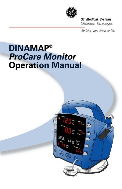
DINAMAP ®<br />
<strong>ProCare</strong> Monitor<br />
Operation Manual
Contents<br />
Introduction<br />
Reissues and Updates...................................................................................................................... 3<br />
Errors and Omissions ....................................................................................................................... 3<br />
Hierarchy of Warnings and Cautions........................................................................................... 4<br />
About the DINAMAP ® <strong>ProCare</strong> Monitor .....................................................................................7<br />
Product Compliance ......................................................................................................................10<br />
Symbols ............................................................................................................................................11<br />
Getting Started<br />
Unpacking the Monitor and Accessories ..................................................................................15<br />
Setting up BP Connections ...........................................................................................................15<br />
Setting up SpO 2 Connections .....................................................................................................16<br />
Setting up Temperature Connections ........................................................................................16<br />
Setting up the Printer (Installing the Paper) ...............................................................................17<br />
Power Sources..................................................................................................................................17<br />
Powering the Monitor: Battery and DC Supply .......................................................................17<br />
Replacing the Battery .....................................................................................................................19<br />
Switching the Monitor On and Off ............................................................................................20<br />
Setting the Date and Time ............................................................................................................20<br />
Product Overview<br />
Buttons ..............................................................................................................................................25<br />
Front Panel ...................................................................................................................................... 27<br />
Rear Panel ........................................................................................................................................29<br />
Left-Side Panel .................................................................................................................................30<br />
Right-Side Panel ..............................................................................................................................30<br />
Windows.......................................................................................................................................... 31<br />
Indicators ..........................................................................................................................................31<br />
Operating Modes ...........................................................................................................................31<br />
Entering Configuration Mode ...................................................................................31<br />
Parameter Modes ...........................................................................................................................32<br />
User Modes .................................................................................................................................... 32<br />
Sounds ..............................................................................................................................................33<br />
Power Sources ................................................................................................................................34<br />
Specifications ...................................................................................................................................35<br />
Mechanical ...................................................................................................................35<br />
Power Requirements ................................................................................................. 35<br />
Environmental ...............................................................................................................36<br />
Printer<br />
Description .......................................................................................................................................41<br />
Installing the Paper .........................................................................................................................41<br />
Print Button ......................................................................................................................................41<br />
Printer Alarms ...................................................................................................................................42<br />
Storage ............................................................................................................................................. 42<br />
Alarms<br />
Alarm Codes ....................................................................................................................................45<br />
Adjusting Alarm Limits.................................................................................................................. 45<br />
Alarms Button ..............................................................................................................45
Adjusting the Alarm Volume ....................................................................................................... 46<br />
Silencing and Acknowledging an Alarm ....................................................................................46<br />
Silence Button............................................................................................................. 46<br />
Alarm Sounds ..................................................................................................................................46<br />
Alarm Detection and Priorities ....................................................................................................47<br />
Limit Alarms ..................................................................................................................47<br />
Parameter Status Alarms ............................................................................................48<br />
Printer Alarms ..............................................................................................................48<br />
Battery Alarms ..............................................................................................................48<br />
Memory Alarms ...........................................................................................................48<br />
System Failure Alarms ................................................................................................48<br />
Specifications ...................................................................................................................................49<br />
Alarm Message Codes ...................................................................................................................50<br />
History<br />
Description...................................................................................................................................... 55<br />
Buttons Associated with History .................................................................................................55<br />
Erasing Stored History.................................................................................................55<br />
Windows Associated with History...............................................................................................56<br />
Indicators Associated with History ............................................................................................ 56<br />
BP<br />
Description...................................................................................................................................... 59<br />
Buttons Associated with BP ..........................................................................................................62<br />
Windows Associated with BP ......................................................................................................62<br />
Indicators Associated with BP.......................................................................................................63<br />
Parameter Modes ............................................................................................................................63<br />
BP Modes of Operation ............................................................................................................... 64<br />
Manual BP Determinations .......................................................................................64<br />
Auto Cycle Determinations ......................................................................................64<br />
STAT BP Determinations ...........................................................................................65<br />
User Settings................................................................................................................................... 66<br />
Mode Settings...............................................................................................................66<br />
Limit Settings ............................................................................................................... 66<br />
Neonate Settings.............................................................................................66<br />
Menu Settings .................................................................................................................................67<br />
Sounds Associated with B..............................................................................................................67<br />
Procedures .......................................................................................................................................67<br />
Cuff Connections ........................................................................................................69<br />
Quick-Disconnect Air Hose ........................................................................ 69<br />
Neonate Air Hose ..........................................................................................69<br />
Alarms .............................................................................................................................................. 70<br />
Critikon US Patents .....................................................................................................70<br />
European US Patents ..................................................................................................70<br />
Specifications ...................................................................................................................................71<br />
Factory Default Settings .............................................................................................71<br />
SpO 2<br />
NELLCOR ® SpO 2 ............................................................................................................................75<br />
Description .......................................................................................................................................75
Contents<br />
Configuration Settings Associated with SpO 2 ..........................................................................77<br />
Buttons Associated with SpO 2 .....................................................................................................78<br />
Windows Associated with SpO 2 .................................................................................................78<br />
Indicators Associated with SpO 2 ................................................................................................78<br />
Parameter Modes ...........................................................................................................................78<br />
User Settings ....................................................................................................................................79<br />
Limit settings................................................................................................................ 79<br />
Menu Settings .................................................................................................................................79<br />
Sounds Associated with SpO 2......................................................................................................79<br />
Procedures .......................................................................................................................................79<br />
Alarms ...............................................................................................................................................81<br />
Troubleshooting.......................................................................................................... 82<br />
Specifications ...................................................................................................................................85<br />
Measurement Range ..................................................................................................85<br />
Accuracy and Motion Tolerance .............................................................................85<br />
Saturation .........................................................................................................85<br />
Pulse Rate ........................................................................................................85<br />
NELLCOR ® Sensor Accuracy................................................................................... 85<br />
OxiMAX........................................................................................................... 85<br />
OxiCliq .............................................................................................................85<br />
Reusable Sensor Models ...............................................................................86<br />
Factory Default Settings..............................................................................................86<br />
NELLCOR ® Patents .....................................................................................................86<br />
Masimo Set ® SpO 2 ........................................................................................................................ 89<br />
Description .......................................................................................................................................89<br />
Configuration Settings Associated with SpO 2 ..........................................................................92<br />
Buttons Associated with SpO 2 ....................................................................................................93<br />
Windows Associated with SpO 2 .................................................................................................93<br />
Indicators Associated with SpO 2 ................................................................................................93<br />
Parameter Modes ...........................................................................................................................93<br />
User Settings ....................................................................................................................................94<br />
Limit settings ................................................................................................................94<br />
Menu Settings .................................................................................................................................94<br />
Sounds Associated with SpO 2.................................................................................................... 94<br />
Procedures ........................................................................................................................................94<br />
Alarms ...............................................................................................................................................96<br />
Troubleshooting ..........................................................................................................97<br />
Specifications ................................................................................................................................ 100<br />
Measurement Range ............................................................................................... 100<br />
Accuracy and Motion Tolerance .......................................................................... 100<br />
Saturation ...................................................................................................... 100<br />
Pulse Rate ..................................................................................................... 100<br />
Masimo ® Sensor Accuracy ........................................................................ 101<br />
Resolution ..................................................................................................... 101<br />
Low Perfusion Performance....................................................................... 101<br />
Interfering Substances............................................................................................. 101<br />
Sensor Light Source ................................................................................................. 101<br />
Factory Default Settings.......................................................................................... 102<br />
Masimo ® Patents ...................................................................................................... 102
TURBOTEMP<br />
Description .................................................................................................................................... 105<br />
Predictive Mode ....................................................................................................... 105<br />
Monitor Mode .......................................................................................................... 106<br />
Configuration Settings Associated with Temperature .......................................................... 107<br />
Buttons Associated with Temperature .................................................................................... 107<br />
Windows Associated with Temperature ................................................................................ 107<br />
Indicators Associated with Temperature ................................................................................. 107<br />
Measurement in Progress Indicators ................................................................... 107<br />
Predictive Mode .......................................................................................... 107<br />
Measurement NOT in Progress Indicators ......................................................... 108<br />
Parameter Modes ........................................................................................................................ 108<br />
User Settings................................................................................................................................. 109<br />
Menu Settings .............................................................................................................................. 109<br />
Sounds Associated with TURBO´TEMP ............................................................................. 109<br />
Procedures for Oral Predictive Mode Determinations ....................................................... 109<br />
Procedures for Rectal Predictive Mode Determinations .................................................... 110<br />
Procedures for Monitor Mode Determinations (Axillary Determinations) ..................... 110<br />
Alarms ............................................................................................................................................ 113<br />
Specifications ................................................................................................................................ 115<br />
Factory Default Settings .......................................................................................... 115<br />
IVAC ® Patents .............................................................................................................................. 115<br />
Pulse Rate<br />
Description .................................................................................................................................... 119<br />
General Notes .............................................................................................................................. 119<br />
Buttons Associated with Pulse Rate ........................................................................................ 119<br />
Windows Associated with Pulse Rate ..................................................................................... 120<br />
Indicators Associated with Pulse Rate .................................................................................... 120<br />
Parameter Modes ......................................................................................................................... 120<br />
User Settings................................................................................................................................. 120<br />
Limit settings ............................................................................................................. 120<br />
Menu Settings .............................................................................................................................. 120<br />
Sounds Associated with Pulse Rate ......................................................................................... 120<br />
Alarms ............................................................................................................................................. 121<br />
Specifications ................................................................................................................................ 122<br />
Factory Default Settings .......................................................................................... 122<br />
Appendix A: Principles of Noninvasive Blood Pressure Determination<br />
Principles of Noninvasive Blood Pressure Determination .................................................. 125<br />
Systolic Search .......................................................................................................... 126<br />
Reference Used to Determine NIBP Accuracy ................................................. 127<br />
DINAMAP Monitors With Intra-Arterial Reference<br />
(DINAMAP Classic Technology).............................................................. 127<br />
DINAMAP Monitors With Auscultatory Reference<br />
(DINAMAP Auscultatory Technology) ................................................... 127<br />
Appendix B: Maintenance<br />
Maintenance.................................................................................................................................. 131<br />
Cleaning the Monitor .............................................................................................. 131
Contents<br />
Cuff Cleaning and Disinfection ............................................................................. 131<br />
General .......................................................................................................... 131<br />
Materials ........................................................................................................ 131<br />
Procedure ..................................................................................................... 132<br />
Temperature Devices .............................................................................................. 132<br />
SpO 2 Sensors ............................................................................................................ 132<br />
Storage and Battery Care ........................................................................................................... 133<br />
Fuses ............................................................................................................................................... 133<br />
Calibration ..................................................................................................................................... 133<br />
Leak Testing .................................................................................................................................. 133<br />
Disposal of Product Waste ........................................................................................................ 135<br />
Batteries ......................................................................................................................135<br />
Patient Applied Parts ............................................................................................... 135<br />
Packaging Material .................................................................................................. 135<br />
Appendix C: Connection Details<br />
Connection Details ..................................................................................................................... 139<br />
Host Port Connector (rear panel) ......................................................................... 139<br />
Appendix D: Warranty, Service, & Spare Parts<br />
Warranty, Service, and Spare Parts.......................................................................................... 143<br />
Warranty ........................................................................................................................................ 143<br />
Assistance and Parts .................................................................................................................... 143<br />
Repairs ........................................................................................................................................... 144<br />
Packing Instructions .................................................................................................................... 144<br />
Service Manuals........................................................................................................................... 144<br />
Appendix E: Reorder Codes<br />
Reorder Codes ............................................................................................................................. 147
DINAMAP ®<br />
<strong>ProCare</strong> Monitor<br />
Operation Manual<br />
1
DINAMAP ® <strong>ProCare</strong> Monitor<br />
2
DINAMAP ® <strong>ProCare</strong> Monitor<br />
Operation Manual<br />
This manual is for DINAMAP <strong>ProCare</strong> Monitors models 100,<br />
200, 300, and 400, with or without printers.<br />
• <strong>ProCare</strong> 100: BP, Pulse<br />
• <strong>ProCare</strong> 200: BP, Pulse, and Temp<br />
• <strong>ProCare</strong> 300: BP, Pulse, and SpO2 • <strong>ProCare</strong> 400: BP, Pulse, Temp, and SpO2 The model of the Monitor determines which parameters are<br />
in your monitor. Please refer to applicable sections.<br />
Reissues and Updates<br />
Changes occurring between issues are addressed through<br />
Change Information Sheets, Addendums, and replacement<br />
pages. If a Change Information Sheet does not accompany<br />
this manual, it is correct as printed.<br />
Errors and Omissions<br />
If errors or omissions are found in this manual, please notify:<br />
GE <strong>Medical</strong> Systems Information Technologies<br />
Technical Publications<br />
4502 Woodland Corporate Boulevard<br />
Tampa, FL 33614<br />
1-877-274-8456<br />
Part No. 2009360-001 B<br />
The content of this document including all figures and<br />
drawings is proprietary information of GE <strong>Medical</strong> Systems<br />
Information Technologies, provided solely for purposes of<br />
operation, maintenance or repair, and dissemination for<br />
other purposes or copying thereof is prohibited without prior<br />
written consent by GE <strong>Medical</strong> Systems Information<br />
Technologies, Tampa, Florida.<br />
Illustrations may show design models; production units may<br />
incorporate changes.<br />
3
Hierarchy of Warnings and Cautions<br />
A general warning is a statement that alerts the user to the<br />
possibility of injury, death, or other serious adverse reactions<br />
associated with the misuse of the device. A warning relates<br />
to steps in a procedure.<br />
A general caution is a statement that alerts the user to the<br />
possibility of a problem with the device associated with its<br />
use or misuse. Such problems include device malfunction,<br />
device failure, damage to the device or damage to other<br />
property. A caution relates to steps in a procedure.<br />
© GE <strong>Medical</strong> Systems Information Technologies 2002. All<br />
rights reserved. TAMPA, FL 33614<br />
Printed in the U.S.A. All rights reserved.<br />
United States<br />
GE <strong>Medical</strong> Systems Information Technologies<br />
4502 Woodland Corporate Boulevard<br />
Tampa, FL 33614<br />
European Representative<br />
GE <strong>Medical</strong> Systems<br />
Information Technologies GmbH<br />
Postfach 60 02 65<br />
D-79032 Freiburg, Germany<br />
Tel. +49 761 45 43 - 0<br />
Fax +49 761 45 43 - 233<br />
4
Introduction
About the DINAMAP ® <strong>ProCare</strong> Monitor<br />
The <strong>ProCare</strong> Monitor provides a small, portable, easy-to-use<br />
monitoring alternative for sub-acute hospital and nonhospital<br />
settings. The battery-operated Monitor offers<br />
noninvasive determination of systolic blood pressure,<br />
diastolic blood pressure, mean arterial pressure, pulse rate,<br />
oxygen saturation, and temperature. Monitors are available<br />
with or without integrated printers. <strong>ProCare</strong> Monitors are<br />
intended for use in various markets, from the physician’s<br />
office to sub-acute triage and medical/surgical units.<br />
• <strong>ProCare</strong> 100: BP, Pulse<br />
• <strong>ProCare</strong> 200: BP, Pulse, and Temp<br />
• <strong>ProCare</strong> 300: BP, Pulse, and SpO2 • <strong>ProCare</strong> 400: BP, Pulse, Temp, and SpO2 The model of the Monitor determines which parameters are<br />
in your monitor. Please refer to applicable sections.<br />
Using the <strong>ProCare</strong> Monitor, a clinician can view, print, and<br />
recall clinical data that is derived from each parameter. The<br />
Monitor is also capable of alerting the clinician to changes in<br />
the patient’s condition or when it is unable to effectively<br />
monitor the patient’s condition. All of the main operations of<br />
the <strong>ProCare</strong> Monitor are easy-to-use and only a button-touch<br />
away. Please review the factory default settings and, where<br />
applicable, enter settings appropriate for your use.<br />
Indications<br />
The <strong>ProCare</strong> Monitor is intended to monitor one patient at a<br />
time in a clinical setting.<br />
Contraindications<br />
This device is not designed, sold, or intended for use except<br />
as indicated.<br />
Federal law (U.S.A.) restricts this device to sale by or on the<br />
order of a clinician.<br />
7<br />
Introduction
Warnings<br />
• Do not use the <strong>ProCare</strong> Monitor in the presence of<br />
magnetic resonance imaging (MRI) devices. There have<br />
been reports of sensors causing patient burns when<br />
operating in an MRI environment.<br />
• Do not use the Monitor in the presence of flammable<br />
anesthetics.<br />
• To help prevent unintended current return paths with<br />
the use of high frequency (HF) surgical equipment,<br />
ensure that the HF surgical neutral electrode is<br />
properly connected.<br />
• To avoid personal injury, do not perform any servicing<br />
unless qualified to do so.<br />
• WARNING: These Monitors should not be used on<br />
patients who are connected to cardiopulmonary bypass<br />
machines.<br />
• If powering the Monitor from an external power<br />
adapter or converter, use only GE <strong>Medical</strong> Systems<br />
Information Technologies-approved power adapters<br />
and converters.<br />
• The Monitor does not include any user-replaceable<br />
fuses. Refer servicing to qualified service personnel.<br />
• To reduce the risk of electric shock, do not remove the<br />
cover or the back. Refer servicing to a qualified service<br />
person.<br />
• If the accuracy of any determination reading is<br />
questionable, first check the patient’s vital signs by<br />
alternate means and then check the <strong>ProCare</strong> Monitor<br />
for proper functioning.<br />
Cautions<br />
• Do not use replacement batteries other than the type<br />
supplied with the Monitor. Replacement batteries are<br />
available from GE <strong>Medical</strong> Systems - Accessories and<br />
Supplies.<br />
•The <strong>ProCare</strong> Monitor is designed to conform to<br />
Electromagnetic Compatibility (EMC) standard IEC<br />
601-1-2, 1993 and will operate accurately in<br />
8
conjunction with other medical equipment which also<br />
meets this requirement. To avoid interference problems<br />
affecting the Monitor, do not use the Monitor in the<br />
presence of equipment which does not conform to<br />
these specifications.<br />
• Place the <strong>ProCare</strong> Monitor on a rigid, secure surface.<br />
Monitor must only be used with mounting hardware,<br />
poles, and stands recommended by GE <strong>Medical</strong><br />
Systems Information Technologies.<br />
• The weight of the accessory basket contents should not<br />
exceed 5 lb (2.7kg).<br />
• Arrange the external AC/DC power converter, air<br />
hoses, and all cables carefully so they do not constitute<br />
a hazard.<br />
• Verify calibration of BP parameter (temp and pulse<br />
oximeter do not require calibration). Ensure that the<br />
display is functioning properly before operating the<br />
<strong>ProCare</strong> Monitor.<br />
• Do not immerse the Monitor in water. If the Monitor is<br />
splashed with water or becomes wet, wipe it<br />
immediately with a dry cloth.<br />
• Do not gas sterilize or autoclave.<br />
•The <strong>ProCare</strong> Monitor, when used with GE <strong>Medical</strong><br />
Systems Information Technologies-approved applied<br />
parts and accessories, is protected against defibrillator<br />
damage.<br />
Note<br />
• The electromagnetic compatibility profile of the <strong>ProCare</strong><br />
Monitor may change if accessories other than those<br />
specified for use with the <strong>ProCare</strong> Monitor are used.<br />
9<br />
Introduction
Product Compliance<br />
The DINAMAP ® <strong>ProCare</strong> Monitor is classified in the following<br />
categories for compliance with IEC 601-1:<br />
• Internally powered or Class II when powered from<br />
external supply<br />
•Transportable<br />
• For continuous operation<br />
• Not suitable for use in the presence of flammable anesthetics<br />
• Not for use in the presence of an oxygen-enriched<br />
atmosphere (oxygen tent)<br />
• Type BF applied parts<br />
• IPX1, degree of protection against ingress of water<br />
• Sterilization/Disinfection, see Appendix B<br />
• Software is developed in accordance with IEC 601-1-4.<br />
• This equipment is suitable for connection to public<br />
mains via power adaptors as defined in CISPR 11.<br />
•The SpO2 parameter conforms to EN 865:1997 with<br />
the exception of Clauses 36, 48, sub-clause<br />
51.108.1and to ISO 9919.<br />
• Defibrillation protected. When used with the<br />
recommended accessories, the Monitor is protected<br />
against the effects of defibrillator discharge. If<br />
monitoring is disrupted by the defibrillation, the<br />
Monitor will recover.<br />
0086<br />
DINAMAP ® PROCARE MONITOR<br />
CLASSIFIED WITH RESPECT TO ELECTRIC SHOCK, FIRE<br />
AND MECHANICAL AND OTHER SPECIFIED HAZARDS<br />
ONLY IN ACCORDANCE WITH CAN/CSA C22.2 NO.<br />
601.1. ALSO EVALUATED TO IEC-601-2-30.<br />
This product conforms with the essential requirements<br />
of the <strong>Medical</strong> Device Directive. Accessories without<br />
the CE mark are not guaranteed to meet the Essential<br />
Requirements of the <strong>Medical</strong> Device Directive.<br />
10
Symbols<br />
The following symbols are associated with the <strong>ProCare</strong><br />
Monitor.<br />
Note: The model of the Monitor determines which symbols<br />
appear on it.<br />
Attention, consult accompanying documents<br />
Silence<br />
Alarms<br />
+ / - Increase / decrease adjustable settings<br />
Menu<br />
Inflate/Stop<br />
Cycle<br />
History<br />
Print<br />
On/Off<br />
Battery Power<br />
External communications port connector<br />
Charging<br />
Defibrillator-proof type BF equipment<br />
External DC power input<br />
Class II equipment according to IEC 60536<br />
11
IPX1<br />
12<br />
Packaging label depicting the<br />
transportation and storage<br />
atmospheric pressure range<br />
of 500 to 1060 hPa.<br />
The DINAMAP ® <strong>ProCare</strong> Monitor is protected against<br />
vertically falling drops of water and conforms with the IEC<br />
529 standard at level of IPX1. Vertically falling drops shall<br />
have no harmful effects to the Monitor.
Getting Started
Getting Started<br />
Unpacking the Monitor and Accessories<br />
Before attempting to use the <strong>ProCare</strong> Monitor, take a few<br />
minutes to become acquainted with the Monitor and its<br />
accessories. Unpack the items carefully. This is also a good<br />
time to check for any damage or accessory shortage. If there<br />
is a problem or shortage, contact GE <strong>Medical</strong> Systems<br />
Information Technologies.<br />
It is recommended that all the packaging be retained, in case<br />
the Monitor must be returned for service in the future.<br />
Setting up BP Connections<br />
1. Connect the end of<br />
the air hose that has<br />
quick-release clips to<br />
the BP connector on<br />
the front of the<br />
Monitor. Make sure<br />
that the hose is not<br />
kinked or<br />
compressed.<br />
Note: To disconnect<br />
the hose from the<br />
Monitor, squeeze the quick-release clips together and pull<br />
the plug from the BP connector.<br />
2. Select appropriate cuff size. Measure patient’s limb and<br />
select appropriately sized cuff according to size marked<br />
on cuff or cuff packaging. When cuff sizes overlap for a<br />
specified circumference, choose the larger size cuff.<br />
Precaution: Accuracy depends on use of proper size cuff.<br />
3. Inspect cuff for damage. Replace cuff when aging, tearing,<br />
or weak closure is apparent. Do not inflate cuff when<br />
unwrapped.<br />
Precaution: Do not use cuff if damaged.<br />
4. Connect the cuff to the air hose. Refer to the BP section<br />
for complete cuff connection instructions.<br />
Warning: It is mandatory that the appropriate hose and<br />
cuff combination be used. Any attempt to modify the<br />
hose will inhibit the Monitor from switching between the<br />
neonatal and adult measurement modes.<br />
15
Note: Care should be taken in reconnecting the cuff to a<br />
hose, ensuring that threads of the cuff and hose are in<br />
alignment and no cross-threading occurs.<br />
5. Refer to the BP section of this manual for complete<br />
instructions on taking an accurate BP determination.<br />
Note: Use only CRITIKON ® Blood Pressure Cuffs. The<br />
size, shape, and bladder characteristics can affect the<br />
performance of the instrument. Inaccurate readings may<br />
occur unless CRITIKON ® Blood Pressure Cuffs are used.<br />
Refer to Appendix E for reorder codes.<br />
Setting up SpO2 Connections<br />
1. Plug the appropriate SpO 2 sensor into the SpO 2 sensor<br />
extension cable.<br />
2. Then plug the SpO 2 sensor extension cable into the SpO 2<br />
sensor connector on the Monitor.<br />
3. Refer to the applicable SpO 2 section of this manual for<br />
complete instructions on monitoring SpO 2 .<br />
Setting up Temperature Connections<br />
1. Connect the<br />
temperature probe<br />
cable to the<br />
temperature probe<br />
connector on the<br />
Monitor.<br />
2. Insert the temperature<br />
probe into the probe<br />
holster at the side of<br />
the Monitor.<br />
16
Getting Started<br />
3. Refer to the TURBOTEMP section of this manual for<br />
complete instructions on taking a temperature reading.<br />
Setting up the Printer (Installing the Paper)<br />
1. With the Monitor<br />
powered on, turn it so<br />
that the side with the<br />
printer is facing you.<br />
2. While grasping the side<br />
of the Monitor, lift the<br />
printer door open by<br />
placing your thumb in<br />
the indented area and<br />
pulling. The printer<br />
door will pop open.<br />
3.Place the roll of paper into the<br />
compartment so that the end of<br />
the paper comes off the right-side<br />
of the roll (paper is wound<br />
around the roll clockwise). Push<br />
the roll all the way to the back of<br />
the printer cavity, making sure the<br />
paper extends out of the printer<br />
cavity at least two inches.<br />
4.Firmly press the door to close it.<br />
5.Refer to the Printer section of<br />
this manual for complete<br />
instructions.<br />
Power Sources<br />
The <strong>ProCare</strong> Monitor is designed to operate from an internal<br />
lead-acid battery (see “Specifications” in Product Overview<br />
section).<br />
Note: The <strong>ProCare</strong> Monitor is not designed to operate<br />
without an internal battery.<br />
Powering the Monitor: Battery and DC Supply<br />
Before the <strong>ProCare</strong> Monitor is used for the first time, the<br />
battery should be charged in the Monitor for at least 8 hours.<br />
With external DC power connected, the green CHARGING<br />
indicator will light to indicate that the battery is charging.<br />
17
When the Monitor is operating on battery power and the<br />
BATTERY LOW alarm is not active, the BATTERY indicator is<br />
backlit green. When the Monitor is operating on battery<br />
power and the BATTERY LOW alarm is active, the BATTERY<br />
indicator flashes green, the LOW indicator flashes amber,<br />
and the medium priority alarm sounds until it is<br />
acknowledged. Press the Silence button to acknowledge this<br />
alarm. Once it is acknowledged, the indicators continue to<br />
flash, but the audible alarm is silenced for 10 minutes. Once<br />
the BATTERY LOW condition becomes active, the Monitor<br />
should be connected to a DC power supply to recharge the<br />
battery (refer to “Power Requirements” in Product Overview<br />
section). If the Monitor continues to be used (approx. 10<br />
min) without charging the battery, the Monitor enters a failsafe<br />
mode: all functions are shutdown except for the alarm<br />
error code in the systolic window, and a constant alarm tone<br />
sounds for up to 10 minutes. After 10 minutes the alarm tone<br />
automatically shuts off and the alarm error code remains in<br />
the systolic window.<br />
Battery charging will take<br />
place as long as the Monitor<br />
remains connected to an<br />
external DC power source.<br />
Notes<br />
• To prolong the life of the<br />
battery, keep the<br />
Monitor connected to a<br />
DC power supply<br />
whenever possible. NEVER allow the battery to become<br />
completely discharged. A fully charged battery will<br />
power the Monitor for approximately 2 hours. To ensure<br />
full charge cycles, replace only with a recommended<br />
battery. If the Monitor is to be stored for some time, first<br />
charge the battery and then remove it and store it<br />
separately from the Monitor.<br />
18
Getting Started<br />
Replacing the Battery<br />
1. Unplug the Monitor from the DC power source.<br />
2. Looking at the bottom of the <strong>ProCare</strong> Monitor, remove<br />
the battery compartment cover by removing the four<br />
screws that secure the cover and help card tray.<br />
3. Remove the help card tray and battery door cover.<br />
3. Remove the old battery and disconnect the wires. Attach<br />
the battery wires to the new battery, ensuring the red<br />
terminal (+) is connected to the red wire and the black<br />
terminal (-) is connected to the black wire.<br />
4. Insert the battery into the compartment.<br />
5. Then replace the cover, help card tray, and screws. Insert<br />
the external DC power converter plug into the external<br />
DC power socket and plug into an AC outlet.<br />
19
General Caution<br />
• Do not touch either the pin of the DC input connector<br />
or the terminals within the battery compartment and<br />
the patient at the same time.<br />
Switching the Monitor On and Off<br />
To switch the <strong>ProCare</strong> Monitor on, push the power On/Off<br />
button.<br />
As the Monitor powers up, it will run a short self-test routine,<br />
which will flash all the indicator lights and then beep the<br />
warning speaker.<br />
To switch the Monitor off, push the power On/Off button<br />
again. This will terminate any measurements that may be in<br />
progress and automatically deflate the cuff. The Monitor also<br />
has an auto turn-off feature, which turns it off after 35<br />
minutes of inactivity.<br />
Setting the Date and Time<br />
To set the date and time on the <strong>ProCare</strong> Monitor, you must<br />
first access the configuration mode. The following list shows<br />
which settings appear in which windows.<br />
Setting: Window Text in Window<br />
• Day: Diastolic<br />
• Month: MAP/Cuff<br />
• Year: Systolic<br />
• Hour: min<br />
• Minute: min<br />
Procedures<br />
1. With the Monitor off, press and hold the Menu button at<br />
the same time as pressing the On/Off button for 3<br />
seconds.<br />
2. The Monitor automatically switches on in configuration<br />
mode.<br />
20
Getting Started<br />
3. To set the date and time, press the Menu button to move<br />
from one setting to another. (You will need to press the<br />
Menu button several times until the year setting appears.)<br />
Use the +/- buttons to increment or decrement the<br />
individual settings. Once you are finished changing a<br />
setting, press the Menu button again to move to the next<br />
setting.<br />
Note: For the date and time to be saved, you must<br />
advance the menu through the min setting.<br />
4. To exit config mode, press the On/Off button.<br />
21
Product Overview
Product Overview<br />
Buttons<br />
1 Silence button: Press to mute audible alarms. Any alarm<br />
active that is acknowledgeable is also removed whenever<br />
this key is pressed. When pressed after alarm sounds<br />
(silence active), the silence icon (bell) lights to indicate<br />
that audible alarms have been silenced for 2 minutes<br />
2 Alarms button: Press to view or adjust parameter alarm<br />
settings<br />
3 +/- button (Plus/Minus): Press the + button to increase an<br />
adjustable setting and the - button to decrease an<br />
adjustable setting. This button is active only when a usersetting<br />
mode (limit or menu) is active<br />
4 Menu button: Press to access menu settings that can be<br />
adjusted while in clinical mode (i.e., ALARM VOLUME,<br />
PULSE VOLUME, INFLATE PRESSURE; refer to Operating<br />
Modes in this section for a description of clinical mode)<br />
5 SpO 2 sensor connector: SpO 2 sensor extension cable<br />
attaches here<br />
6 BP connector: BP cuff hose attaches here<br />
7 Inflate/Stop button: Press to start a manual BP<br />
determination or stop any BP determination<br />
8 Temperature probe holster: Temperature probe is stored<br />
here<br />
9 Cycle button: Press to start Auto Cycle or STAT mode<br />
25
10 Temperature probe cover storage: Box of probe covers is<br />
stored here<br />
11 History button: Press to activate the history mode. When<br />
activated, it displays the most recent entries stored. Press<br />
and hold the button for 2 seconds to clear all entries<br />
stored<br />
12 Print button: Press to print currently displayed values or all<br />
stored entries when in history mode<br />
13 On/Off button: Controls on/off state of monitor; push for<br />
power on and push again for power off<br />
14 Temperature probe connector: Temperature probe cable<br />
attaches here<br />
26
Product Overview<br />
Front Panel<br />
15 Silence icon: when Silence button is pressed after alarm<br />
sounds (silence active), silence icon (bell) lights to indicate<br />
that audible alarms have been silenced for 2 minutes<br />
16 Systolic window: 3-digit red LED indicates measured<br />
systolic BP in mmHg<br />
17 Diastolic window: 3-digit red LED indicates measured<br />
diastolic BP in mmHg<br />
18 Alarm volume indicator: lights to indicate you are making<br />
a change to the alarm volume<br />
19 Pulse volume: lights to indicate you are making a change<br />
to the pulse volume<br />
20 Inflate pressure: lights to indicate you are making a<br />
change to the inflation pressure<br />
21 Pulse Rate window: 3-digit yellow LED shows pulse rate in<br />
beats per minute<br />
22 SpO 2 pulse indicator: Red LED bar flashes to indicate that<br />
real-time pulse rate measurements are being derived from<br />
SpO 2 signals<br />
23 SpO 2 window: 3-digit red LED indicates oxygen saturation<br />
in %<br />
27
24 MAP/Cuff window: 3-digit red LED indicates measured<br />
MAP in mmHg and shows instantaneous cuff pressure<br />
during BP determination<br />
25 Min window: Displays the BP mode if manual or STAT is<br />
the cycle time when in Auto Cycle mode<br />
26 Battery power indicator: Green LED indicates the Monitor<br />
is operating on battery power<br />
27 Low battery power indicator: Yellow LED indicates LOW<br />
charge status of internal battery<br />
28 Charging indicator: Green LED indicates presence of<br />
external power source and battery charging<br />
29 Temperature window: 4-digit red LED indicates measured<br />
temperature<br />
28
Product Overview<br />
Rear Panel<br />
30 Data interface connector: Host communications port<br />
(15 pin D-type RS-232 serial port) for use only with<br />
equipment conforming to IEC 601-1, configured to<br />
comply with IEC 601-1-1<br />
31 Printer compartment<br />
29
Left-Side Panel<br />
32 Printer compartment<br />
Right-Side Panel<br />
33 External DC power socket: To be used with approved GE<br />
<strong>Medical</strong> Systems Information Technologies AC-DC power<br />
converter ONLY<br />
30
Product Overview<br />
Windows<br />
Each derived vital sign has an associated window for<br />
displaying the value. For each window, the vital sign’s name<br />
and unit of measure are labeled above and to the right of it,<br />
respectively. An additional window--the min window--is<br />
available for displaying the BP mode or chosen AUTO<br />
CYCLE selection.<br />
Indicators<br />
Indicators are text messages and icons that are positioned on<br />
the front of the Monitor and can be either backlit red or<br />
green. For each vital sign that has user-adjustable limits, two<br />
indicators (HIGH, LOW) appear to the right of its window.<br />
Operating Modes<br />
The <strong>ProCare</strong> Monitor can operate in one of four modes:<br />
clinical, configuration, advanced configuration, and service.<br />
Clinical mode is the Monitor’s normal operating mode.<br />
While this mode is active, alarm limits and a few other<br />
commonly used settings are adjustable. All parameters are<br />
available for monitoring in this mode.<br />
Configuration and advanced configuration modes display the<br />
software revision and allows you to configure defaults for<br />
some settings that are available in clinical mode, as well as<br />
some less commonly used settings that are only adjustable in<br />
these modes. No parameters are operable in these modes,<br />
therefore, patient monitoring should be suspended.<br />
Entering Configuration Mode<br />
1. With the Monitor off, press and hold the Menu button at<br />
the same time as pressing the On/Off button for 3<br />
seconds.<br />
2. The Monitor automatically switches on in configuration<br />
mode.<br />
Refer to the Service Manual for instructions for use<br />
concerning advanced configuration and service mode.<br />
31
Parameter Modes<br />
The <strong>ProCare</strong> Monitor has three parameter modes: offline,<br />
ready, or operate.<br />
A parameter is in offline mode when its vital sign(s) are not<br />
checked against user-set limits, alarm conditions detected by<br />
the parameter do not generate alarms, and no vital sign(s)<br />
data is displayed.<br />
A parameter is in ready mode when its vital signs are not<br />
checked against user-set limits, alarm conditions detected by<br />
the parameter do not generate alarms, and no vital sign(s)<br />
data is displayed. However, information regarding the<br />
connection of a sensor is communicated in this mode.<br />
A parameter is in operate mode when the appropriate vital<br />
signs are being checked against user-set limits and alarming<br />
conditions detected by the parameter generate alarms. Vital<br />
sign(s) data from the parameter is displayed.<br />
When the Monitor is turned on and no sensor is connected,<br />
the parameter remains in offline mode. Upon detection of a<br />
sensor, the parameter auto-switches to ready mode. Upon<br />
detection of valid patient data, the parameter auto-switches<br />
to operate mode.<br />
User Modes<br />
The <strong>ProCare</strong> Monitor has four user modes that are available<br />
during clinical operating mode: Menu, Cycle, Limit<br />
Adjustment, and History.<br />
The Menu mode allows you to access and change the three<br />
settings associated with the following indicators: ALARM<br />
VOLUME, PULSE VOLUME, AND INFLATE PRESSURE. To<br />
activate this mode, press the Menu button. With each press<br />
of the Menu button, the indicator appears in flashing green<br />
with the associated value appearing in red in the Diastolic<br />
window. As the Menu button is pressed, the indicators<br />
appear in the following order: ALARM VOLUME, PULSE<br />
VOLUME, AND INFLATE PRESSURE. To change the<br />
associated value, simply use the +/- button to increment or<br />
decrement, respectively. After 15 seconds of not pressing the<br />
32
Product Overview<br />
Menu button, the Menu mode is automatically exited.<br />
Otherwise, you can exit the Menu mode by pressing the<br />
Menu button one more time after viewing the oldest entry.<br />
Upon exiting Menu mode, the main monitoring screen is<br />
displayed. Alarm and pulse volume settings are retained after<br />
power-off. INFLATE PRESSURE is reset to its configured<br />
default after power-off.<br />
The Cycle mode allows you to access Auto Cycle and STAT<br />
modes. Refer to the BP section for more information.<br />
The History mode allows you to access the stored patient<br />
data. Refer to the History section for more information.<br />
The Limit Adjustment mode allows you to change alarm<br />
limit settings that are used while monitoring a patient. All<br />
limit alarm settings return to their default settings after<br />
power-off. The range and increment/decrement steps for<br />
each derived vital sign that has adjustable limits are<br />
described in each parameter section. The step size specified<br />
(which cannot be adjusted) tells how much the limit value<br />
will change per increment/decrement key press and also<br />
dictates how close together a pair of limits can be.<br />
Limit-adjustable vital signs are displayed in the following<br />
order: Systolic (HIGH, LOW), Diastolic (HIGH, LOW), Pulse<br />
Rate (HIGH, LOW), and SpO 2 (HIGH, LOW).<br />
Note: The Temperature and MAP (mean arterial pressure)<br />
vital signs are not checked against alarm limits.<br />
Sounds<br />
The Monitor generates sounds based upon user interaction,<br />
parameter events, parameter and system alarms, and low<br />
battery alarms.<br />
User interaction sounds include positive key tone and<br />
negative key tone. The positive key tone sounds one highpitched<br />
tone when you press a button and the Monitor is<br />
able to perform the intended function. The negative key tone<br />
sounds three low-pitched tones when you press a button and<br />
the Monitor is unable to perform the intended function.<br />
33
Parameter-specific sounds are related to the functioning of<br />
each parameter: NIBP, Temperature, and SpO 2 . Refer to the<br />
individual parameter sections for definitions and sounds.<br />
Alarm-specific sounds include medium and high priority. The<br />
medium-priority alarm sounds three high-pitched tones. The<br />
high-priority alarm sounds three high-pitched tones followed<br />
by two high-pitched tones. When alarms of both priorities<br />
are active, only the high-priority alarm sound is audible.<br />
A sound is generated when AC power is lost while patient<br />
monitoring is active.<br />
Power Sources<br />
The <strong>ProCare</strong> Monitor is designed to operate from an internal<br />
lead-acid battery. For replacement rechargeable batteries,<br />
please refer to the Service section of this manual.<br />
34
Product Overview<br />
Specifications<br />
Mechanical<br />
Dimensions Height: 9.7 in (24.7 cm)<br />
Width: 8.6 in (21.9 cm)<br />
without Temperature<br />
10.0 in (25.4 cm) with Temp<br />
Depth: 5.3 in (13.5 cm)<br />
Weight, Including Battery 5.68 lb (2.58 kg)<br />
Mountings Self-supporting on rubber feet<br />
Portability Carried by handle<br />
Classification Information Mode of operation:<br />
continuous<br />
Degree of protection against<br />
harmful ingress of water: Dripproof<br />
IPX1<br />
Power Requirements<br />
Power Converter US: P/N: 2009460-001<br />
Protection against electrical<br />
shock: Class II<br />
AC input: 120 VAC/60 Hz<br />
24W<br />
DC output voltage; 12VDC<br />
at 1A<br />
The AC mains power adapter<br />
contains a nonresettable and<br />
nonreplaceable fuse.<br />
Power Converter UK & EUR: P/N UK: 2008538-001<br />
P/N EUR: 2009539-001<br />
Protection against electrical<br />
shock: Class II<br />
AC input: 230-240 VAC/50 Hz<br />
92mA<br />
DC output voltage; 12VDC<br />
at 1A<br />
35
36<br />
The AC mains power adapter<br />
contains a nonresettable and<br />
nonreplaceable fuse.<br />
Monitor Protection against electrical<br />
shock: Internally powered or<br />
Class II when powered from<br />
specified external power<br />
supply.<br />
DC input voltage: 12 VDC,<br />
supplied from a source<br />
conforming to IEC 601-1.<br />
Fuses: The Monitor contains<br />
four fuses. The fuses are autoresettable<br />
and mounted within<br />
the Monitor. The fuses protect<br />
the low voltage DC input, the<br />
battery, the remote alarm<br />
output, and the +5 V output<br />
on the host port connector.<br />
Battery: 6 volt, 3.3 amp-hours<br />
protected by internal autoresetting<br />
fuse and thermal<br />
protection.<br />
Minimum operation time: 2<br />
hrs (5 min cycle with adult cuff<br />
at 25 °C, SpO 2 active at 60<br />
bpm, Temp in monitor mode,<br />
printout of current values<br />
every 5 min) from full charge.<br />
Time for full recharge: Approx.<br />
5 hrs from full discharge when<br />
the Monitor is switched off and<br />
approx. 8 hrs when the Monitor<br />
is switched on.<br />
Environmental<br />
Operating Temperature + 5 °C to + 40 °C<br />
(+ 41 °F to + 104 °F)<br />
Operating Atmospheric<br />
Pressure 700 hPa to 1060 hPa
Product Overview<br />
Storage Temperature – 20 °C to + 50 °C<br />
(– 4 °F to + 122 °F)<br />
Storage/Transportation<br />
Atmospheric Pressure 500 hPa to 1060 hPa<br />
Humidity Range 5% to 95% noncondensing<br />
Radio Frequency Complies with IEC<br />
Publication 601-1-2 (April<br />
1993) <strong>Medical</strong> Electrical<br />
Equipment, Electromagnetic<br />
Compatibility Requirements<br />
and Tests and CISPR 11<br />
(Group 1, Class B) for radiated<br />
and conducted emissions.<br />
IPX1<br />
The DINAMAP ® <strong>ProCare</strong> Monitor is<br />
protected against vertically falling drops of<br />
water and conforms with the IEC 529<br />
standard at level of IPX1. No harmful<br />
effects will come of vertically falling drops<br />
of water making contact with the Monitor.<br />
37
Printer
41<br />
Printer<br />
Description<br />
The <strong>ProCare</strong> Monitor comes with an optional text-only<br />
printer. Each time a printout is started, the following<br />
information is printed: GE <strong>Medical</strong> Systems header, monitor<br />
name; model number; current software revision; a place for<br />
patient name and hand-written comments; a place for the<br />
column labels, parameter labels, or unit of measure; date;<br />
and vital signs data, if available. On some models, a pencil<br />
icon appears instead of the name and comments labels.<br />
Installing the Paper<br />
Refer to the Getting Started section for instructions.<br />
Print Button<br />
The Print button initiates two types of printouts: currently<br />
displayed values and History.<br />
By pressing the Print button while the main monitoring<br />
screen is viewable, a printout of the currently displayed<br />
values is generated. Since the currently displayed values may<br />
have been derived at different times (e.g., the BP values are 5<br />
minutes old, while Temp was just completed), the Monitor<br />
prints the value along with a time stamp of when that value<br />
was derived. Values are printed in order of the most recent<br />
to the oldest.<br />
By pressing the Print button when in History mode, all<br />
entries currently stored in the history are printed in order of<br />
the most recent to the oldest.<br />
Note: If the Print button was pressed during the first 10<br />
seconds of SpO 2 monitoring, dashes will appear for SpO 2<br />
and pulse rate readings.<br />
The availability of the printer is determined at the time the<br />
printout is started. When the printer is unavailable, the Print<br />
button makes a negative key sound when you press it. The<br />
printer is unavailable if it is out of paper, too hot, or if the<br />
battery is too low, or if the Monitor is in any of the following<br />
modes: Cycle, Alarm limit adjustment, Menu, config, or service.<br />
If no print is visible on the paper, check that the paper roll<br />
has been installed in the correct position (refer to diagram).
To tear off the printout, use a slight sideways action to pull<br />
the paper sharply up across the edge of the door.<br />
Printer Alarms<br />
When any of the alarm conditions occur, the alarm code<br />
flashes in the min window and a high-priority alarm sounds.<br />
When a printer alarm condition is active, you can<br />
acknowledge the alarm by pressing the Silence button.<br />
E10: PRINTER NO PAPER<br />
This alarm is generated when the Print button is pressed and<br />
the printer detects that there is no paper.<br />
E11: PRINTER TOO HOT<br />
This alarm is generated when a printout is in progress and the<br />
printer becomes too hot to print.<br />
E12: BATTERY TOO LOW TO PRINT<br />
This alarm is generated when a printout is in progress and the<br />
battery becomes too low to print.<br />
Storage<br />
Store thermal paper in a cool, dry place. The printed strip<br />
(thermal paper recording) should not be<br />
• exposed to direct sunlight,<br />
• exposed to temperatures over 100 °F/38 °C or relative<br />
humidity over 80%,<br />
• placed in contact with adhesives, adhesive tapes, or<br />
plasticizers such as those found in all PVC page<br />
protectors.<br />
Note: When in doubt about long-term storage conditions,<br />
store a photocopy of the thermal paper recording.<br />
Cautions<br />
• The paper is thermally activated; therefore, do not store<br />
it in a hot place as discoloration may result.<br />
• Use only replacement paper rolls (P/N 770137 for<br />
single rolls, 089100 for box of 10) from GE <strong>Medical</strong><br />
Systems - Accessories and Supplies.<br />
42
Alarms
45<br />
Alarms<br />
The <strong>ProCare</strong> Monitor provides visible and audible indications<br />
of patient-, and system-related alarm conditions. An alarm<br />
can generate an audible indication, visual indication, alarm<br />
message code, and electronic record in the history.<br />
Alarm Codes<br />
All alarm indications are accompanied by an audible signal<br />
unless the Silence button is selected. A microprocessor<br />
system failure will generate a high-pitched audible alarm<br />
regardless of the setting of the Silence button.<br />
There are three categories of alarms: patient-related (limit<br />
and parameter status alarms), system-related (printer, battery,<br />
and memory alarms), and system failures.<br />
Adjusting Alarm Limits<br />
Alarms Button<br />
Pressing the Alarms button activates the limit adjustment<br />
user mode. When the limit adjustment mode is initially<br />
activated, it first displays the systolic high limit value with the<br />
HIGH indicator flashing in red. With each subsequent press<br />
of the Alarms button, the next limit in the sequence is<br />
displayed for adjustment. Press the + button to increase the<br />
displayed limit value and the - button to decrease the<br />
displayed limit value.<br />
To exit limit adjustment mode after setting alarms, you must<br />
progress through all limits until you reach the last one. Then,<br />
after reaching the last limit, immediately press the Alarms<br />
button. The main monitoring screen appears indicating that<br />
you have exited Alarms mode. If monitoring is active, the<br />
current vital signs appear after you have completed your<br />
alarm setting changes. Or, you can let the mode timeout by<br />
not touching the Alarms button until the main monitoring<br />
screen appears indicating that you have exited Alarms mode.<br />
The Monitor returns to all default limit settings after poweroff;<br />
these defaults are adjustable via configuration mode.<br />
Adjustable vital signs limits are displayed in the following<br />
order: Systolic (HIGH, LOW), Diastolic (HIGH, LOW), Pulse<br />
Rate (HIGH, LOW), and SpO 2 (HIGH, LOW). Refer to each<br />
parameter section for ranges.
Note: The Temperature and MAP vital signs are not checked<br />
against alarm limits.<br />
Adjusting the Alarm Volume<br />
You can adjust the alarm volume by pressing the Menu<br />
button. ALARM VOLUME will flash in green with the value in<br />
the Diastolic window. You can set the ALARM VOLUME<br />
range from 1 to 10 (10 being the loudest). Changing the<br />
volume applies to all alarms.<br />
The positive key tone that sounds when you press the +/-<br />
buttons relates directly to the user-set alarm volume. Refer to<br />
User Modes.<br />
Silencing and Acknowledging an Alarm<br />
Silence Button<br />
To silence a patient-related alarm (limit and parameter status<br />
alarms) at anytime, press the Silence button. The silence icon<br />
(a bell) lights to indicate that audible alarms have been<br />
silenced for 2 minutes.<br />
Some patient- and system-related alarms are<br />
acknowledgeable. (Refer to the Alarm Message Codes table<br />
at the back of this section.) For acknowledgeable alarms that<br />
are active when the Silence button is pressed, any associated<br />
audible or visual indication is removed and any associated<br />
alarm message code is no longer displayed.<br />
The silence icon has three states:<br />
• Solid red: silence icon is active.<br />
• Blinking red: alarm silence is not active and at least one<br />
alarm condition is active.<br />
• Off: alarm silence is not active and no alarm condition is<br />
active.<br />
Alarm Sounds<br />
The Monitor produces two different alarm sounds based<br />
upon the priority of the alarm: medium and high priority. The<br />
medium-priority alarm sounds three high-pitched tones. The<br />
high-priority alarm sounds three high-pitched tones followed<br />
46
47<br />
Alarms<br />
by two high-pitched tones. When alarms of both priorities<br />
are active, only the high-priority alarm sound is audible.<br />
Alarm Detection and Priorities<br />
Limit Alarms<br />
The Monitor checks each derived vital sign (except MAP and<br />
Temperature) against user-set limits. A high-limit alarm is<br />
generated when that value is greater than its high limit. A<br />
low-limit alarm is generated when that value is less than its<br />
low limit. All limit alarms are considered high priority.<br />
Parameter Range Default<br />
Systolic High 35 - 290 200<br />
Systolic Low 30 - 285 80<br />
Diastolic High 15 - 220 120<br />
Diastolic Low 10 - 215 30<br />
Pulse Rate High: NELLCOR 35 - 250 150<br />
Pulse Rate Low: NELLCOR 30 - 245 50<br />
Pulse Rate High: MASIMO 35 - 235 150<br />
Pulse Rate Low: MASIMO 30 - 230 50<br />
SpO 2 High 21 - 100 100<br />
SpO 2 Low 20 - 99 90<br />
When a limit violation occurs, the following happens:<br />
• The derived vital sign that is out of limits and the<br />
associated HIGH or LOW indicator flash.<br />
• The high priority alarm sound becomes audible unless<br />
silence is active.<br />
Parameter Status Alarms<br />
The Monitor generates parameter status alarms when<br />
unusual patient or sensor conditions are detected. All
parameter status alarms are considered high priority alarms.<br />
Refer to the Alarm Message Codes table in this section.<br />
When a parameter status alarm occurs, the following<br />
happens:<br />
• Its code flashes in the associated window.<br />
• The high priority alarm sound becomes audible unless<br />
alarm silence is active.<br />
Printer Alarms<br />
Refer to Printer section.<br />
Memory Alarms<br />
Memory alarms occur when battery-backed RAM is<br />
corrupted. When it occurs, all settings are reset to their<br />
factory defaults. When detected, the alarm message code<br />
appears in the Systolic window and the medium-priority<br />
alarm sounds.<br />
Battery Alarms<br />
Refer to “Powering the Monitor” in the Getting Started<br />
section.<br />
System Failure Alarms<br />
System failures are caused by a system software or hardware<br />
failure. When a system failure occurs, the error code is<br />
displayed in the Systolic window, and the Monitor enters a<br />
fail-safe mode in which a constant alarm tone sounds for up<br />
to 10 minutes before the tone is automatically switched off.<br />
Refer to the Alarm Message Codes table in this section.<br />
48
Specifications<br />
Default Settings<br />
Alarm Volume 5<br />
49<br />
Alarms
Alarm<br />
Message<br />
Code<br />
Alarm Detected<br />
50<br />
Acknowledgeable by<br />
pressing Silence?*<br />
E89 BP NO DETERMINATION Yes<br />
E85 BP LEVEL TIMEOUT Yes<br />
E84 BP TOTAL TIMEOUT Yes<br />
E83 BP INFLATION TIMEOUT Yes<br />
E82 EXCESS AIR IN CUFF Yes<br />
E80 BP OVERPRESSURE Yes<br />
E20 SPO2 NO SENSOR Yes<br />
E21 SPO2 REPLACE SENSOR Yes<br />
E22<br />
SPO2 REPOSITION SENSOR<br />
(Masimo ONLY)<br />
Yes<br />
E23 SPO2 SENSOR OFF FINGER Yes<br />
E25 SPO2 NO SIGNAL Yes<br />
E61 TEMP PROBE BROKEN No<br />
E63<br />
TEMP DISCONNECTED OR<br />
WRONG TYPE PROBE<br />
Yes<br />
E66 TEMP PROBE TOO HOT No<br />
E10 PRINTER NO PAPER Yes<br />
E11 PRINTER TOO HOT Yes<br />
E12 BATTERY TOO LOW TO PRINT Yes<br />
E00 MEMORY LOST Yes
Alarm<br />
Message<br />
Code<br />
Alarm Detected<br />
51<br />
Alarms<br />
Acknowledgeable by<br />
pressing Silence?*<br />
930 SYSTEM FAILURE** No<br />
940 SYSTEM FAILURE** No<br />
950 SYSTEM FAILURE** No<br />
951 SYSTEM FAILURE** No<br />
952 SYSTEM FAILURE** No<br />
970 SYSTEM FAILURE** No<br />
971 SYSTEM FAILURE** No<br />
972 SYSTEM FAILURE** No<br />
973 SYSTEM FAILURE** No<br />
974 SYSTEM FAILURE** No<br />
975 SYSTEM FAILURE** No<br />
*Acknowledging an alarm by pressing the Silence button, cancels the alarm.<br />
** Refer to the <strong>ProCare</strong> Service Manual for definitions and instructions.
History
55<br />
History<br />
Description<br />
The History mode allows you to access the stored patient<br />
data. The <strong>ProCare</strong> Monitor can hold up to 25 stored entries<br />
in history. When full, the oldest entry is removed so the most<br />
recent entry can be stored. Additionally, entries are<br />
automatically removed when they become older than 24 hours.<br />
The age of each entry is maintained and displayed in the min<br />
window with a minus sign (-) in front of it when other data<br />
stored for that entry is displayed. For entries that are greater<br />
than 59 minutes old, the age is displayed as HH:MM<br />
(hour:min). For entries that are less than or equal to 59<br />
minutes old, the age is displayed in total minutes.<br />
When viewing entries in History that are out of limits, the<br />
corresponding HIGH or LOW indicator appears in red.<br />
An entry is stored in history at the completion of a BP<br />
determination and at the completion of a successful<br />
predictive temperature measurement. At the end of a BP<br />
determination, systolic, diastolic, MAP, pulse rate, and SpO 2<br />
values are stored. At the end of a temperature determination,<br />
only the temperature value is stored.<br />
Buttons Associated with History<br />
To activate the History mode, press the History button. The<br />
HISTORY indicator flashes green while this mode is active.<br />
With each press of the History button, the patient data<br />
stored with the next oldest entry is displayed. Entries are<br />
displayed from the most recent to the oldest. For example,<br />
the most recent entry could have an age of -0 minutes and<br />
the oldest entry could have an age of -23:59.<br />
After 15 seconds of not pressing the History button, the<br />
History mode is automatically exited. Otherwise, you can<br />
exit the History mode by pressing the History button one<br />
more time after viewing the oldest entry. Upon exiting<br />
History mode, the main monitoring screen is displayed.<br />
Erasing Stored History<br />
To erase stored patient data, press and hold the History<br />
button for a minimum of 2 seconds. All entries that were
stored in history, as well as any patient data displayed on the<br />
Monitor that relates to the previous determination or the<br />
previous temperature measurement is erased.<br />
Windows Associated with History<br />
Each window on the Monitor can be active during History<br />
mode. When the History button is pressed the patient data<br />
stored for each entry is displayed in the applicable windows.<br />
Patient data is displayed from most recent to oldest,<br />
indicated by the age in the min window.<br />
Indicators Associated with History<br />
The History indicator is used to show the state of the history<br />
mode. When History mode is active, the History indicator<br />
flashes green.<br />
56
59<br />
BP<br />
Description<br />
The BP parameter in the <strong>ProCare</strong> Monitor is available with<br />
two types of BP technologies: one calibrated to intra-arterial<br />
pressure and one calibrated to the auscultatory method<br />
(specific technologies are available in select markets). Please<br />
refer to the front of your <strong>ProCare</strong> Monitor to see which BP<br />
technology your monitor contains. The monitors containing<br />
auscultatory technology will have an auscultatory label<br />
above the model number on the front of the Monitor. Then,<br />
refer to the Appendix A: Principles of Noninvasive Blood<br />
Pressure Determination for specific information regarding<br />
both technologies. All user interface options, instructions for<br />
use, and alarms will be the same for both technologies. The<br />
BP parameter is included in all models. Blood pressure is<br />
monitored noninvasively in the <strong>ProCare</strong> Monitor by<br />
oscillometric method.<br />
Note: For neonatal populations, the reference is always the<br />
intra-arterial pressure monitoring method.<br />
The <strong>ProCare</strong> Monitor has three BP modes: 1. Manual, 2. Auto<br />
Cycle, and 3. STAT. The mode is selected by the user. The<br />
actual BP determination is automated and, once it is<br />
complete, the values for systolic pressure, diastolic pressure,<br />
mean arterial pressure, and pulse rate are shown in their<br />
respective windows.<br />
Before each BP determination, the Monitor performs a test<br />
to ensure that the cuff pressure is below a specified level.<br />
The determination is delayed until this condition is met. The<br />
Monitor senses the type of hose being used and<br />
automatically uses adult/pediatric monitoring parameters or<br />
neonatal monitoring parameters, as appropriate.<br />
Audible and visible alarms occur when any of the values for<br />
systolic pressure, diastolic pressure, or pulse rate are outside<br />
their selected high or low limits.<br />
Note: The Monitor will continue to operate until the battery<br />
is completely depleted in order to obtain the full use of the<br />
battery. However, if the battery reaches its “empty” point<br />
during a BP determination, it will simply stop in the middle of<br />
the determination.
Instructions for cleaning and disinfecting BP cuffs are in<br />
Appendix B.<br />
General Warnings<br />
• Connect cuffs and inflation systems only to systems<br />
designed for non-invasive blood pressure monitoring.<br />
Devices with luers and locking luer connectors may be<br />
inadvertently connected to intravascular fluid systems<br />
that may allow air to be pumped into a blood vessel.<br />
•The <strong>ProCare</strong> Monitor will not measure blood pressure<br />
effectively on patients who are experiencing seizures or<br />
tremors.<br />
• Arrhythmias will increase the time required by the<br />
<strong>ProCare</strong> Monitor to determine a blood pressure and<br />
may extend the time beyond the capabilities of the<br />
Monitor.<br />
• In Manual mode, the <strong>ProCare</strong> Monitor displays the<br />
results of the last blood pressure determination for 30<br />
minutes or until another determination is completed. If<br />
a patient’s condition changes between one<br />
determination and the next, the Monitor will not detect<br />
the change or indicate an alarm condition.<br />
• Devices that exert pressure on tissue have been<br />
associated with purpura, skin avulsion, compartmental<br />
syndrome, ischemia and/or neuropathy. To minimize<br />
these potential problems, especially when monitoring<br />
at frequent intervals or over extended periods of time,<br />
make sure the cuff is applied appropriately and<br />
examine the cuff site and the limb distal to the cuff<br />
regularly for signs of impeded blood flow.<br />
• Do not apply external pressure against cuff while<br />
monitoring. Doing so may cause inaccurate blood<br />
pressure values.<br />
• Use care when placing cuff on extremity used to<br />
monitor other patient parameters.<br />
•The <strong>ProCare</strong> Monitor is designed for use only with<br />
CRITIKON ® dual-tube cuffs.<br />
60
61<br />
BP<br />
• Use only accessories approved for use with DINAMAP ®<br />
Monitors. Failure to use recommended accessories may<br />
result in inaccurate readings.<br />
• Blood pressure cuffs should be removed from the<br />
patient when the Monitor is powered off. If the<br />
extremity remains cuffed under these conditions or if<br />
the interval between blood pressure determinations is<br />
prolonged, the patient’s limb should be observed<br />
frequently and the cuff placement site should be<br />
rotated as needed.<br />
General Cautions<br />
• Accuracy of BP measurement depends on using a cuff<br />
of the proper size. It is essential to measure the<br />
circumference of the limb and to select the proper size<br />
cuff. In addition, the air hoses are color-coded<br />
according to patient population. The gray 12- or 24-foot<br />
hose (3.66 m or 7.3 m) is required on patients who<br />
require cuff sizes from infant through thigh cuffs. The<br />
light blue 12-foot hose (3.66 m) is required for the<br />
neonatal cuff sizes #1 through #5.<br />
• If it becomes necessary to move the cuff to another<br />
limb, make sure the appropriate size cuff is used.<br />
• The pulse rate derived from a BP determination may<br />
differ from the heart rate derived from an EKG<br />
waveform because the <strong>ProCare</strong> Monitor measures<br />
actual peripheral pulses, not electrical signals or<br />
contractions from the heart. Differences may occur<br />
because electrical signals at the heart occasionally fail<br />
to produce a peripheral pulse or the patient may have<br />
poor peripheral perfusion. Also, if a patient’s beat-tobeat<br />
pulse amplitude varies significantly (e.g., because<br />
of pulsus alternans, atrial fibrillation, or the use of a<br />
rapid-cycling artificial ventilator), blood pressure and<br />
pulse rate readings can be erratic, and an alternate<br />
measuring method should be used for confirmation.<br />
General Notes<br />
• A patient’s vital signs may vary dramatically during the<br />
use of cardiovascular agents such as those that raise or
lower blood pressure or those that increase or decrease<br />
heart rate.<br />
• Several conditions may cause the BP parameter to<br />
calculate and display only the mean arterial pressure<br />
(MAP) without systolic and diastolic readings. These<br />
conditions include very low systolic and amplitude<br />
fluctuations, so an accurate calculation for these values<br />
can’t be made (e.g., patient in shock); too small of a<br />
difference between systolic and MAP calculations in<br />
relationship to the difference between diastolic and<br />
MAP; or a leak has occurred in the <strong>ProCare</strong> Monitor. If<br />
only the MAP value is displayed, an alarm message<br />
code is displayed in the systolic window, while the<br />
diastolic window remains blank.<br />
• This equipment is suitable for use in the presence of<br />
electrosurgery.<br />
Buttons Associated with BP<br />
The buttons associated with BP are Inflate/Stop and Cycle.<br />
The Inflate/Stop button starts and stops BP determinations.<br />
When a determination is in progress, pressing this button<br />
stops the determination. While in STAT mode, pressing this<br />
button cancels STAT mode, as well a determination if in<br />
progress. When in Auto Cycle mode, pressing this button<br />
starts a determination or cancels a determination if in<br />
progress; it does not change the mode.<br />
Note: While an E80: BP OVERPRESSURE alarm is active, all<br />
presses of this button are ignored.<br />
The Cycle button initiates the Cycle mode, which is where<br />
you can choose STAT or an auto cycle time. Cycle mode<br />
selections appear in the following order: Stat, 1, 2, 3, 4, 5,<br />
10, 15, 20, 30, 60, 90, 120 (minutes), and - - (two dashes).<br />
Choose Stat to start STAT mode. Choose 1-120 to select the<br />
desired cycle time and start Auto Cycle mode. When you<br />
reach the desired setting, do not press the Cycle button<br />
again. After 2 seconds the cycle mode is deactivated.<br />
Choose the two dashes to cancel Auto Cycle mode.<br />
Note: While an E80: BP OVERPRESSURE alarm is active, all<br />
presses of this button are ignored.<br />
62
63<br />
BP<br />
Windows Associated with BP<br />
The windows associated with BP are Systolic, Diastolic,<br />
MAP/Cuff, Pulse Rate, and min. The Systolic, Diastolic,<br />
MAP/Cuff, and Pulse Rate (if SpO 2 is not active) windows<br />
are automatically cleared when a new BP determination is<br />
started. In manual mode, the displayed information is also<br />
cleared when it becomes older than 30 minutes.<br />
The Systolic and Diastolic windows display values after a<br />
determination has completed successfully. While in STAT<br />
mode, the Systolic window flashes the early systolic value if it<br />
is available.<br />
The MAP/Cuff window displays the derived mean arterial<br />
pressure (MAP) following the completion of a successful<br />
determination. During any type of BP determination, the<br />
pressure inside the cuff appears in this window.<br />
The min window displays the BP mode of operation and the<br />
age of the previous BP determination. When both types of<br />
information are present, they flash alternately in this window.<br />
When in Manual mode, two dashes (- -) are displayed. When<br />
in Auto Cycle mode, the chosen Cycle time is displayed (e.g.,<br />
15) When in STAT mode, Stat is displayed. When displayed,<br />
the age of the previous BP determination is preceded by a<br />
minus sign (e.g., - 5).<br />
Indicators Associated with BP<br />
The indicators associated with BP are Systolic HIGH and<br />
LOW, Diastolic HIGH and LOW, AUTO CYCLE and<br />
HISTORY.<br />
The AUTO CYCLE indicator appears solid green when Auto<br />
mode is on. It flashes green when changes are being made to<br />
the current BP mode (e.g., Cycle mode is active). The<br />
HISTORY indicator appears solid green when the age of the<br />
previous BP determination is displayed in the min window.<br />
Parameter Modes<br />
The BP parameter is in operate mode upon power-up. It does<br />
not have a ready mode.
BP Modes of Operation<br />
The <strong>ProCare</strong> Monitor has three BP modes: 1. Manual, 2. Auto<br />
Cycle, and 3. STAT. The mode is selected by the user. BP<br />
determinations are automated and, upon completion, the<br />
values for systolic pressure, diastolic pressure, mean arterial<br />
pressure, and pulse rate are shown in their respective<br />
windows.<br />
Manual BP Determinations<br />
Manual mode allows you to take one blood pressure<br />
determination. Manual mode is always the BP mode of<br />
operation upon power-up. A normal, uninterrupted Manual<br />
determination takes about 40 seconds. Following a<br />
determination, the cuff pressure must drop below 5 mmHg<br />
(neonate) or 15 mmHg (adult) before another determination<br />
can be started.<br />
Manual BP determinations are started by pressing the<br />
Inflate/Stop button. To stop a Manual BP determination<br />
press the Inflate/Stop button. The values displayed in the<br />
Systolic, Diastolic, MAP, and Pulse Rate (if SpO 2 is not<br />
active) windows are cleared after 30 minutes have lapsed.<br />
Auto Cycle Determinations<br />
Auto Cycle mode allows you to take multiple determinations<br />
at user-defined intervals. In the Auto Cycle mode, the<br />
pressure must be below 5 mmHg (neonate) or 15 mmHg<br />
(adult) for at least 30 seconds before the next auto<br />
determination can be started.<br />
Auto Cycle mode is started by selecting the Cycle button.<br />
When in Auto Cycle mode, the AUTO CYCLE indicator<br />
appears solid green. Manual determinations can be taken<br />
while in Auto Cycle mode without affecting when the next<br />
auto determination is to start. You can also change the time<br />
interval while in Auto Cycle mode.<br />
Once the Cycle button is pressed, the first Auto Cycle<br />
determination is started, and the time between<br />
determinations appears in the min window. You can change<br />
the time interval between Auto Cycle determinations by<br />
continuing to press the Cycle button until you reach the<br />
64
65<br />
BP<br />
desired time interval. Time interval selections appear in the<br />
following order: Stat, 1, 2, 3, 4, 5, 10, 15, 20, 30, 60, 90, 120<br />
(minutes), and - - (two dashes). When you reach the desired<br />
time interval, do not press the Cycle button again; after 2<br />
seconds, the chosen time interval is retained and remains in<br />
the min window.<br />
Pressing the Cycle button when in Auto Cycle mode<br />
activates Cycle mode again with two dashes (- -) appearing in<br />
the min window. If you press the Cycle button immediately<br />
after the first press, the next time interval appears in the min<br />
window. If you do not press the Cycle button immediately<br />
after the first press, Cycle mode is deactivated. Press the<br />
Inflate/Stop button to stop the determination in progress<br />
without canceling the Auto Cycle mode. Choose the two<br />
dashes (- -) to cancel Auto Cycle mode.<br />
If the first Auto Cycle determination results in a limit alarm,<br />
another repeat determination is taken to verify the alarm.<br />
This occurs only once.<br />
Whenever an Auto Cycle determination results in a E89: BP<br />
NO DETERMINATION alarm, up to nine more repeat<br />
determinations are attempted in order to achieve valid<br />
values. If at any time during this repeat cycle, the BP NO<br />
DETERMINATION alarm is acknowledged by pressing the<br />
Silence button or the Inflate/Stop button, additional<br />
determinations are not attempted. If the repeat cycle<br />
completes all nine repeat determinations without reaching a<br />
valid value, the Monitor returns to normal Auto Cycle mode.<br />
However, an Auto Cycle mode determination must<br />
complete successfully before a repeat cycle will follow a<br />
future Auto Cycle mode determination that results in an E89:<br />
BP NO DETERMINATION alarm.<br />
STAT BP Determinations<br />
STAT mode allows you to take as many determinations as<br />
possible within a 5-minute time period. The Monitor will<br />
begin another determination once the pressure is below 5<br />
mmHg for 8 seconds (neonates) or 15 mmHg for 4 seconds<br />
(adults), unless the 5-minute period has ended or STAT mode<br />
has been canceled.
Note: BP and BP-derived pulse rate alarm limits are disabled<br />
while in Stat mode.<br />
STAT BP determinations are started by selecting the Cycle<br />
button. Once the Cycle button is pressed, choose Stat. The<br />
Monitor automatically begins a 5-minute period of STAT<br />
determinations.<br />
Note: If the Monitor was previously in Auto mode, the first<br />
STAT BP determination begins after 2 seconds.<br />
After the first STAT determination, an early systolic value<br />
flashes in the associated window. If STAT mode is started<br />
when a determination is already in progress, that<br />
determination becomes the first in the series of STAT<br />
determinations. At the end of STAT mode, the BP mode prior<br />
to entering STAT mode is resumed. To cancel STAT mode,<br />
press the Inflate/Stop button.<br />
User Settings<br />
Mode Settings<br />
There is one mode setting associated with this parameter:<br />
Cycle. The Cycle mode is started by pressing the Cycle<br />
button. While the Cycle mode is active, Cycle selections are<br />
displayed in the min window. Cycle selections appear in the<br />
following order: Stat, 1, 2, 3, 4, 5, 10, 15, 20, 30, 60, 90,<br />
120, - - .<br />
Limit Settings<br />
There are two limit settings associated with this parameter:<br />
HIGH and LOW. Both limit settings are available for Systolic<br />
and Diastolic windows. The range for Systolic HIGH is 35 to<br />
290 mmHg; the range for Systolic LOW is 30 to 285 mmHg.<br />
The range for Diastolic HIGH is 15 to 220 mmHg; the range<br />
for Diastolic LOW is 10 to 215 mmHg. The settings appear in<br />
increments of 5 mmHg.<br />
Neonate Settings<br />
The Monitor determines if a neonate BP cuff is being used<br />
and then checks the systolic limit and adjusts it to an<br />
appropriate limit for neonates.<br />
66
67<br />
BP<br />
Menu Settings<br />
The INFLATE PRESSURE menu setting is associated with the<br />
BP parameter. This option lets you adjust the target pressure<br />
that the Monitor initially pumps to for the next<br />
determination. The settings appear in increments of 5<br />
mmHg. The range available is 100 mmHg to 250 mmHg. If<br />
the Monitor senses a neonate BP cuff in use, it checks the<br />
systolic limit and adjusts it to an appropriate limit for<br />
neonates.<br />
When you change the target pressure, any values from the<br />
previous determinations are cleared from their associated<br />
windows.<br />
Manual determinations use the value chosen for INFLATE<br />
PRESSURE as their target inflation pressure unless a<br />
determination is started within 2 minutes of the completion<br />
of a previous determination. For a determination that is<br />
started within 2 minutes of the previous determination, the<br />
target inflation pressure is adaptive (calculates the target<br />
inflation pressure based on the previous determination). For<br />
all Auto Cycle and STAT determinations (with the exception<br />
of the first determination of the series), the target inflation<br />
pressure is always adaptive.<br />
Sounds Associated with BP<br />
There is one tone associated with this parameter: a single<br />
tone. The tone sounds at the completion of any BP<br />
determination.<br />
Procedures<br />
1. Connect the end of the air hose which has quick-release<br />
clips to the BP connector on the front of the Monitor.<br />
Make sure that the hose is not kinked or compressed.<br />
Note: To disconnect the hose from the Monitor, squeeze<br />
the quick-release clips together and pull the plug from the<br />
BP connector.<br />
2. Select the appropriate blood pressure measurement site.<br />
Because normative values are generally based on this site<br />
and as a matter of convenience, the upper arm is<br />
preferred. When upper arm size or shape, the patient’s
clinical condition, or other factors prohibit use of the<br />
upper arm, the clinician must plan patient care<br />
accordingly, taking into account the patient’s<br />
cardiovascular status and the effect of an alternative site<br />
on blood pressure values, proper cuff size, and comfort.<br />
The figure shows the recommended sites for placing cuffs.<br />
Warning: Do not place the cuff on a limb being used for<br />
intravenous infusion or any area where circulation is<br />
compromised or has the potential to be compromised.<br />
3. If patient is standing, sitting, or inclined, ensure that cuffed<br />
limb is supported to maintain cuff at level of patient’s<br />
heart. If cuff is not at heart level, the difference in systolic<br />
and diastolic values due to hydrostatic effect must be<br />
considered. Add 1.80 mmHg to values for every inch<br />
(2.54 cm) above heart level. Subtract 1.80 mmHg from<br />
values for every inch (2.54 cm) below heart level.<br />
4. Select appropriate cuff size. Measure patient’s limb and<br />
select appropriately sized cuff according to size marked<br />
on cuff or cuff packaging. When cuff sizes overlap for a<br />
specified circumference, choose the larger size cuff.<br />
Precaution: Accuracy depends on use of proper size cuff.<br />
Caution: Do not use an infant cuff with an auscultatory<br />
reference DINAMAP ® <strong>ProCare</strong> Monitor. The neonatal<br />
#5 cuff and neonatal hose may be used on patients with<br />
an arm circumference of 8 - 15 cm.<br />
Note: Use only CRITIKON ® Blood Pressure Cuffs. The<br />
size, shape, and bladder characteristics can affect the<br />
performance of the instrument. Inaccurate readings may<br />
occur unless CRITIKON ® Blood Pressure Cuffs are used.<br />
5. Inspect cuff for damage. Replace cuff when aging, tearing,<br />
or weak closure is apparent. Do not inflate cuff when<br />
unwrapped.<br />
68
69<br />
BP<br />
Precaution: Do not use cuff if structural integrity is<br />
suspect.<br />
6. Connect the cuff to the air hose.<br />
7. Inspect patient’s limb prior to application.<br />
Precaution: Do not apply cuff to areas where skin is not<br />
intact or tissue is injured.<br />
8. Palpate artery and place cuff so that patient’s artery is<br />
aligned with cuff arrow marked “artery.”<br />
9. Squeeze all air from cuff and confirm that the connection<br />
is secure and unoccluded and that tubing is not kinked.<br />
10.Wrap cuff snugly around the patient’s limb. Cuff index<br />
line must fall within the range markings. Ensure that hook<br />
and loop closures are properly engaged so that pressure<br />
is evenly distributed throughout cuff. If upper arm is used,<br />
place cuff as far proximally as possible.<br />
11.Proper cuff wrapping should be snug, but should still<br />
allow space for a finger between patient and cuff. Cuff<br />
should not be so tight as to prevent venous return<br />
between determinations.<br />
Warning: Using a cuff that is too tight will cause venous<br />
congestion and discoloration of the limb, but using a<br />
cuff that is too loose may result in no readings and/or<br />
inaccurate readings.<br />
12.Proceed with monitoring in the Manual, Auto Cycle, or<br />
STAT mode.<br />
Cuff Connections<br />
Quick-Disconnect<br />
Air Hose<br />
Push and twist the male<br />
slip hose connector into<br />
the cuff connector to<br />
ensure a tight fit.
Neonate Air Hose<br />
Push and twist the male<br />
slip hose connector into<br />
the cuff connector to<br />
ensure a tight fit.<br />
Alarms<br />
Alarm Acknowledgeable<br />
by pressing Silence?<br />
BP SYSTOLIC HIGH yes<br />
BP SYSTOLIC LOW yes<br />
BP DIASTOLIC HIGH yes<br />
BP DIASTOLIC LOW yes<br />
E89: BP NO DETERMINATION yes<br />
E85: BP LEVEL TIMEOUT yes<br />
E84: BP TOTAL TIMEOUT yes<br />
E83: BP PUMP TIMEOUT yes<br />
E80: BP OVERPRESSURE yes<br />
E82: EXCESS AIR IN CUFF yes<br />
The alarm codes appear in the Systolic window. When an<br />
alarm is active, it can be acknowledged by starting a new<br />
determination, with the exception of the E80: BP<br />
OVERPRESSURE alarm. BP OVERPRESSURE can only be<br />
acknowledged by pressing the Silence button. During STAT<br />
mode determinations, systolic, diastolic and BP-derived pulse<br />
rate values are not checked against their limits.<br />
Critikon US Patents<br />
4,360,029; 4,501,280; 4,546,775; 4,638,810; 5,052,397;<br />
4,349,034; 4,543,962; 4,627,440; 4,754,761; 5,170,795<br />
European Patents<br />
EP122123, EP205805, EP207807<br />
70
71<br />
BP<br />
Specifications<br />
Cuff Pressure Range 0 to 290 mmHg (adult/ped)<br />
(Normal operating range) 0 to 140 mmHg (neonate)<br />
Blood Pressure Accuracy Meets or exceeds ANSI/AAMI<br />
standard SP-10 (mean error ≤5<br />
mmHg, standard deviation ≤8<br />
mmHg)<br />
Maximum Determination 120 s (adult/ped)<br />
Time 85 s (neonate)<br />
Overpressure Cutoff 300 to 330 mmHg (adult/ped)<br />
150 to 165 mmHg (neonate)<br />
Pulse Rate Range 30 to 200 beats/min (adult/ped)<br />
30 to 220 beats/min (neonate)<br />
Pulse Rate Accuracy ± 3.5%<br />
Factory Default Settings<br />
Systolic Limits (mmHg) HIGH: 200<br />
LOW: 80<br />
Diastolic Limits (mmHg) HIGH: 120<br />
LOW: 30<br />
Inflation Pressure 160 mmHg (adult/ped)<br />
110 mmHg (neonate)<br />
Cycle button 15<br />
All DINAMAP ® Monitor regulatory and accuracy studies<br />
have been performed using CRITIKON ® Blood Pressure<br />
Cuffs. Use only CRITIKON ® Blood Pressure Cuffs. The<br />
size, shape, and bladder characteristics can affect the<br />
performance of the instrument. Inaccurate readings may<br />
occur unless CRITIKON ® Blood Pressure Cuffs are used.
SpO 2
NELLCOR* OxiMAX SpO2<br />
NELLCOR ® SpO 2<br />
Description<br />
The SpO 2 parameter in the <strong>ProCare</strong> Monitor is available in<br />
two different leading technologies: NELLCOR ® and<br />
MASIMO SET ® . Please refer to the front of your Monitor to<br />
see which SpO 2 technology your monitor contains. The<br />
SpO 2 technology logo will be on the front fascia of the<br />
Monitor. This section refers to NELLCOR ® SpO 2 technology.<br />
The SpO 2 parameter is included in Models 300 and 400. To<br />
begin SpO 2monitoring, plug the sensor into the NELLCOR ®<br />
DOC-10 sensor extension cable, then plug the cable into the<br />
Monitor. Simply place the SpO 2 sensor on the patient’s<br />
finger; monitoring begins automatically. Functional oxygen<br />
saturation (SpO 2) of arterial blood is noninvasively and<br />
continuously monitored in the <strong>ProCare</strong> Monitor using pulse<br />
oximetry technology from NELLCOR ® . Functional SpO 2 is<br />
the ratio of oxygenated hemoglobin to hemoglobin that is<br />
capable of transporting oxygen. This ratio, expressed as a<br />
percentage, is shown in the SpO 2 window, which is<br />
continually updated.<br />
Pulse rate derived from SpO 2 appears in the Pulse Rate<br />
window. A tone sounds at a rate corresponding to the pulse<br />
rate and at a pitch corresponding to the SpO 2 saturation<br />
level. The pitch is highest at 100% oxygen saturation, and it<br />
continuously decreases as the saturation level falls. The<br />
Monitor displays a pulse amplitude bar. The pulse amplitude<br />
bar graph is proportional to the arterial blood flow.<br />
Audible and visible alarms occur when SpO 2 levels are<br />
outside the alarm limits. When a parameter status alarm<br />
occurs, an alarm message code appears in the SpO 2<br />
window.<br />
Note: Limit alarms, printing, and trending are not available<br />
for the first 10 seconds of SpO 2 monitoring.<br />
*NELLCOR ® is a trademark of Nellcor Puritan Bennett<br />
75
General Warnings<br />
• Do not place SpO2 sensor on patient during magnetic<br />
resonance imaging (MRI). Adverse reactions include<br />
potential burns to patients as a result of contact with<br />
attachments heated by the MRI radio frequency pulse,<br />
potential degradation of the magnetic resonance<br />
image, and potential reduced accuracy of SpO2 measurements. Always remove oximetry devices and<br />
attachments from the MRI environment before<br />
scanning a patient.<br />
• The use of cardio-green and other intravascular dyes at<br />
certain concentrations may affect the accuracy of the<br />
SpO2 measurement.<br />
•The SpO2 function is calibrated to read functional<br />
arterial oxygen saturation. Significant levels of<br />
dysfunctional hemoglobins such as carboxyhemoglobin<br />
or methemoglobin may affect the accuracy of the SpO2 measurement.<br />
• Pulse oximetry readings and pulse signals can be<br />
affected by certain environmental conditions, sensor<br />
application errors, and certain patient conditions. See<br />
the appropriate sections of this manual for specific<br />
safety information.<br />
• The use of accessories, transducers, and cables other<br />
than those specified may result in increased emission<br />
and/or decreased immunity and inaccurate readings of<br />
the Monitor.<br />
General Cautions<br />
• As with any clip-on sensor, pressure is exerted. The<br />
clinician should be cautious in using a clip-on sensor on<br />
patients with compromised circulation (e.g., because of<br />
peripheral vascular disease or vasoconstricting<br />
medications).<br />
• Do not perform any testing or maintenance on a sensor<br />
while it is being used to monitor a patient.<br />
• Bright light sources (e.g., infrared heat lamps, bilirubin<br />
lights, direct sunlight, operating room lights) may<br />
interfere with the performance of the SpO2 function.<br />
76
NELLCOR ® SpO 2<br />
To prevent such interference, cover the sensor with<br />
opaque material.<br />
General Notes<br />
• A patient’s vital signs may vary dramatically during the<br />
use of cardiovascular agents such as those that raise or<br />
lower blood pressure or those that increase or decrease<br />
pulse rate.<br />
•The <strong>ProCare</strong> Monitor that is labeled with NELLCOR ®<br />
Technology is compatible only with NELLCOR ® OxiMAX<br />
sensors and NELLCOR ® DOC-10 sensor extension cable.<br />
• Software development, software validation, and Risk and<br />
Hazard Analysis has been performed to a registered<br />
quality system.<br />
• User or patient-applied parts are latex-free.<br />
Configuration Settings Associated with SpO 2<br />
There are two configuration settings associated with this<br />
parameter: Response Mode (n0d) and SatSeconds (SAt).<br />
Response Mode (n0d) allows the user to specify the<br />
averaging technique to optimize measurements in the<br />
presence of various patient movement. Choose Mode 1<br />
(Normal Response) when patients are active as in exercise<br />
protocols. Choose Mode 2 (Fast Response; default setting)<br />
for the general patient population. The configuration of this<br />
setting affects whether the pulse rate derived from SpO 2 is<br />
displayed in the Pulse Rate window while SpO 2 is in operate<br />
mode. If Mode 1 is chosen, the pulse rate is not displayed. If<br />
Mode 2 is chosen, the pulse rate is displayed.<br />
With traditional alarm management, upper and lower alarm<br />
limits are set for monitoring SpO 2 . During monitoring, as<br />
soon as an alarm limit is violated by as little as one<br />
percentage point, an audible alarm immediately sounds.<br />
When the % SpO 2 fluctuates near an alarm limit, the alarm<br />
sounds each time the limit is violated. To prevent these<br />
nuisance alarms, the <strong>ProCare</strong> Monitor uses the SatSeconds<br />
technique. The SatSeconds technique (SAt) limit-controls<br />
the time that the % SpO 2 level may fall outside the alarm<br />
77
efore an audible alarm sounds. Choose either 0, 10, 25, 50,<br />
or 100 seconds. If 0 is chosen this limit hold-off feature is<br />
disabled.<br />
The SatSeconds “Safety Net” is for patients with saturation<br />
levels having frequent excursions below the limit, but not<br />
staying below the limit long enough for the SatSeconds<br />
time setting to be reached. When 3 or more limit violations<br />
occur within 60 seconds, an alarm sounds even if the<br />
SatSeconds time setting has not been reached.<br />
Buttons Associated with SpO 2<br />
There are no buttons associated with this parameter.<br />
Windows Associated with SpO 2<br />
There is one window associated with this parameter: SpO 2 .<br />
While in offline mode, nothing is displayed in the SpO 2<br />
window. When in ready mode and the parameter senses that<br />
a sensor is connected, a single dash (-) appears in this<br />
window. When it is in operate mode and the parameter is<br />
reporting a valid data, the derived SpO 2 value appears in this<br />
window. The values are displayed in %.<br />
Note: If SpO 2 is the source for Pulse Rate, the Pulse Rate<br />
window is associated with this parameter.<br />
Indicators Associated with SpO 2<br />
There is one indicator associated with this parameter: the<br />
pulse amplitude indicator bar. The red LED bar flashes to<br />
indicate that pulse rate measurements are being derived<br />
from SpO 2 signals and the height of the bar is proportional to<br />
the arterial blood flow.<br />
Parameter Modes<br />
The SpO 2 parameter is in offline mode upon power-up. The<br />
parameter automatically switches from offline to ready mode<br />
when a sensor is connected to the Monitor. The parameter<br />
automatically switches from ready to operate mode when<br />
pulses are detected.<br />
If an SpO 2 SENSOR OFF FINGER or SPO 2 LOST PULSE<br />
alarm is acknowledged, the parameter automatically<br />
switches from operate to ready mode. If a SpO 2 SENSOR<br />
78
NELLCOR ® SpO 2<br />
DISCONNECTED alarm is acknowledged, the parameter<br />
automatically switches from operate to offline mode.<br />
Note: Once either of these alarms have been acknowledged,<br />
SpO 2 monitoring is not resumed until a valid pulse is<br />
detected again.<br />
User Settings<br />
Limit settings<br />
There are two limit settings associated with this parameter:<br />
HIGH and LOW. The range for HIGH is 21 to 100%. The<br />
range for LOW is 20 to 99%. The settings appear in<br />
increments of 1%.<br />
Menu Settings<br />
The PULSE VOLUME menu setting is associated with the<br />
SpO 2 parameter. This option lets you adjust the volume of<br />
the tone that sounds after each detected heartbeat. It can be<br />
adjusted from 0 - 10 (10 being the loudest). If you set the<br />
volume to zero, no tone will sound.<br />
Sounds Associated with SpO 2<br />
An audible tone is provided by the Monitor for each pulse<br />
detected by the NELLCOR ® SpO 2 parameter. The pitch of<br />
the audible tone is directly related to the calculated<br />
saturation value. As the saturation value increases, the pitch<br />
frequency increases continuously with each 1% increase in<br />
SpO 2 . As the saturation value decreases, the pitch frequency<br />
continuously decreases. This audible tone is silenced while<br />
an alarm sounds or the PULSE VOLUME is set to 0. Refer to<br />
“Menu Settings” in this section.<br />
Procedures<br />
1. Select a sensor that is appropriate for the patient and the<br />
clinical situation.<br />
• Use only NELLCOR ® sensors PURPLE and WHITE and<br />
NELLCOR ® DOC-10 pulse oximetery cables. Use of<br />
another pulse oximetry cable will have an adverse effect<br />
on performance. Do not attach any cable that is<br />
intended for computer use to the sensor port. Do not<br />
connect any device other than NELLCOR ® -approved<br />
sensor to the sensor connector.<br />
79
Warning: Do not use a damaged sensor or one with<br />
exposed electrical contacts. Do not use sensor, cables,<br />
or connectors that appear damaged.<br />
Note: Use only NELLCOR ® OxiMAX compatible sensors,<br />
which are available from GE <strong>Medical</strong> Systems -<br />
Accessories and Supplies.<br />
2. Following the directions for use supplied with the sensor,<br />
apply the sensor to the patient.<br />
Warnings<br />
Patient safety:<br />
• If the sensor is are not applied properly, the patient’s<br />
skin could be injured or the ability of the <strong>ProCare</strong><br />
Monitor to measure oxygen saturation could be<br />
compromised. For example, a clip-on sensor should<br />
never be taped shut. Taping the sensor could damage<br />
the patient’s skin or impair the venous return, thus<br />
causing venous pulsation and inaccurate measurement<br />
of oxygen saturation.<br />
• Excessive pressure from the sensor may cause necrosis<br />
of the skin.<br />
• For additional warnings and information, refer to the<br />
NELLCOR ® sensor’s directions for use.<br />
Monitor performance:<br />
•When an SpO2 sensor is on a limb that has a blood<br />
pressure cuff, the SpO2 data will not be valid when the<br />
cuff is inflated. If SpO2 readings are required during<br />
the entire blood pressure determination, attach the<br />
SpO2 sensor to the limb opposite the one with the<br />
blood pressure cuff.<br />
• Remove nail polish and artificial nails. Placing a sensor<br />
on a polished or an artificial nail may affect accuracy.<br />
Cautions<br />
Patient safety:<br />
• Do not place any clip-on sensor in a patient’s mouth or<br />
on a patient’s nose or toe.<br />
• Do not place a clip-on finger sensor on a patient’s<br />
thumb or across a child’s foot or hand.<br />
• The sensor disconnect error message and associated<br />
alarm indicate that the sensor is either disconnected or<br />
80
NELLCOR ® SpO2 the wiring is faulty. The user should check the sensor<br />
connection and, if necessary, replace the sensor, DOC-<br />
10 cable, or both.<br />
• Observe the sensor site frequently to assure adequate<br />
distal circulation. Sensor sites should be checked at<br />
least every 2 hours and rotated at least every 4<br />
hours.<br />
Monitor performance:<br />
• Placing a sensor distal to an arterial line may interfere<br />
with adequate arterial pulsation and compromise the<br />
measurement of SpO2 .<br />
• Place the sensor so that the LEDs and the photodiode<br />
are opposite each other.<br />
3. Plug the SpO2 sensor into the SpO2 sensor extension<br />
cable. Then plug the SpO2 sensor extension cable into the<br />
SpO2 sensor connector.<br />
4. Proceed with monitoring. SpO2 determinations run<br />
continuously and can run simultaneously with other<br />
measurements.<br />
Alarms<br />
Alarm Acknowledgeable<br />
by pressing Silence?<br />
SPO2 HIGH no<br />
SPO2 LOW no<br />
E20: SPO2 SENSOR DISCONNECTED yes<br />
E21: SPO2 REPLACE SENSOR yes<br />
E23: SPO2 SENSOR OFF FINGER yes<br />
E25: SPO2 LOST PULSE no<br />
81
Troubleshooting<br />
This section discusses potential difficulties and suggestions<br />
for resolving them. If the difficulty persists, contact a qualified<br />
service person or your local representative. The service<br />
manual, which is for use by qualified service personnel<br />
provides additional troubleshooting information.<br />
PROBLEM: The pulse amplitude bar indicates a pulse, but no<br />
oxygen saturation or pulse rate values appear on the screen.<br />
CAUSE:<br />
• Excessive patient motion may be making it impossible<br />
for the SpO2 function to find a pulse pattern.<br />
• The sensor may be damaged.<br />
• The patient’s perfusion may be too low to allow the<br />
SpO2 function to measure saturation and pulse rate.<br />
SOLUTION:<br />
Check the patient.<br />
• If possible, keep the patient still; check whether the<br />
SpO2 sensor is applied securely and properly, and<br />
replace it if necessary; move the sensor to a new site; or<br />
use a disposable adhesive sensor that may tolerate more<br />
motion.<br />
• Replace the sensor.<br />
PROBLEM: The SpO2 value or the pulse rate changes<br />
rapidly; the pulse amplitude bar is erratic.<br />
CAUSE:<br />
• Excessive patient motion may be making it impossible<br />
for the SpO2 function to find a pulse pattern.<br />
• An electrosurgical unit (ESU) may be interfering with<br />
performance.<br />
SOLUTION:<br />
Check the patient.<br />
• If possible, keep the patient still; check whether the<br />
sensor is applied securely and properly, and replace it if<br />
necessary; move the sensor to a new site; use a sensor<br />
that tolerates more motion.<br />
If an ESU is interfering:<br />
• Move the SpO2 cable as far from the ESU as possible.<br />
82
NELLCOR ® SpO 2<br />
• Plug the Monitor and the ESU into different AC circuits.<br />
• Move the ESU ground pad as close to the surgical site as<br />
possible.<br />
• The sensor may need to be replaced with a new sensor.<br />
• If the patient weighs less than 3 kg or more than 40 kg,<br />
apply an OXIMAX, reusable sensors (except DS-100,<br />
OXI-A/N, OXI-P/I), or OxiCliq oxygen transducer to an<br />
appropriate site. These sensors have Faraday shields<br />
which provide added protection from high electronic<br />
noise and ambient light.<br />
PROBLEM: The oxygen saturation measurement does not<br />
correlate with the value calculated from a blood gas<br />
determination.<br />
CAUSE:<br />
•The SpO2 calculation may not have correctly adjusted<br />
for the effects of pH; temperature; CO2 ; fetal<br />
hemoglobin; or 2,3-DPG.<br />
• Accuracy can be affected by incorrect sensor application<br />
or use; intravascular dyes; bright light; excessive patient<br />
movement; venous pulsations; electrosurgical<br />
interference; and placement of a sensor on an extremity<br />
that has a blood pressure cuff, arterial catheter, or<br />
intravascular line.<br />
SOLUTION:<br />
• Check that calculations have been corrected<br />
appropriately for the relevant variable. In general,<br />
calculated saturation values are not as reliable as direct<br />
laboratory hemoximeter measurements.<br />
• If there is excessive light, cover the sensor with opaque<br />
material.<br />
• Circulation distal to the sensor site should be checked<br />
routinely. Refer to the directions for use supplied with the<br />
sensor for requirements on moving the sensor to another<br />
site to ensure adhesion, skin integrity, and correct optical<br />
alignment. If skin integrity changes, move the sensor to<br />
another site.<br />
• Try to keep the patient still, or change the sensor site to<br />
one with less motion.<br />
83
• Observe all instructions, warnings, and cautions in this<br />
manual and in the directions for use of the sensor.<br />
PROBLEM: A valid SpO2 signal was present but has<br />
disappeared.<br />
CAUSE:<br />
• A BP determination on the same limb is in progress.<br />
SOLUTION:<br />
Check the patient.<br />
• An alarm message code appears on the screen, and the<br />
audible alarm will sound immediately.<br />
• Move the sensor to the arm that is not connected to a<br />
blood pressure cuff.<br />
PROBLEM: A REPLACE SENSOR error code has been<br />
detected.<br />
CAUSE:<br />
• The sensor or cable may be the wrong type or defective,<br />
the cabling may be improperly connected.<br />
SOLUTION:<br />
Check the patient.<br />
• If possible, keep the patient still; check whether the<br />
proper sensor/cable is applied securely and properly,<br />
and replace it if necessary.<br />
• Disconnect and reconnect the sensor.<br />
PROBLEM: A SENSOR DISCONNECTED error code has<br />
been detected, but the sensor is still connected.<br />
CAUSE:<br />
• The sensor is not completely connected. The sensor<br />
extension cable or sensor wiring is faulty.<br />
SOLUTION:<br />
Check the patient.<br />
• Check the sensor connection to the sensor extension<br />
cable and the sensor extension cable connection to the<br />
monitor. Then, if needed, replace the sensor or the<br />
sensor extension cable.<br />
84
NELLCOR ® SpO 2<br />
Specifications<br />
Measurement Range<br />
SpO2 1 to 100%<br />
Pulse Rate 20 to 250 beats/min<br />
Accuracy and Motion Tolerance<br />
Saturation<br />
Without Motion - Adults* 70 to 100% ±2 digits<br />
Without Motion - Neonate* 70 to 100% ±3 digits<br />
With Motion - Adults/Neo** 70 to 100% ±3 digits<br />
Low Perfusion 70 to 100% ±2 digits<br />
0 to 69% unspecified<br />
Pulse Rate<br />
Without Motion 20 to 250 beats/min ±3 digits<br />
With Motion normal physiologic range<br />
55 to 125 beats/min ±5 digits<br />
Low Perfusion 20 to 250 beats/min ±3 digits<br />
*Adult specifications are shown for OXIMAX MAX-A and MAX-N sensors.<br />
Neonate specifications are shown for OXIMAX MAX-N. Saturation accuracy<br />
will vary by sensor type.<br />
**Applicability: OXIMAX MAX-A, MAX-AL, MAX-P, MAX-I, and MAX-N sensors.<br />
NELLCOR ® Sensor Accuracy<br />
Note: All NELLCOR ® sensors must be used with the<br />
NELLCOR ® DOC-10 cable; the SCP-10 cable is not<br />
compatible with the <strong>ProCare</strong> Monitor.<br />
Sensor Model SpO 2 Range<br />
70% - 100%<br />
OxiMAX<br />
MAX-A*, MAX-AL* ±2 digits<br />
MAX-N* † (Adult) ±2 digits<br />
MAX-N* † (Neonate) ±3 digits<br />
MAX-P* ±2 digits<br />
MAX-I* ±2 digits<br />
MAX-R* ‡<br />
±3.5 digits<br />
OxiCliq ®<br />
OxiCliq A ±2.5 digits<br />
OxiCliq P ±2.5 digits<br />
85
OxiCliq N † (Adult) ±2.5 digits<br />
OxiCliq N † (Neonate) ±3.5 digits<br />
OxiCliq I ±2.5 digits<br />
Reusable Sensor Models<br />
D-YS (Infant to Adult) ±3 digits<br />
D-YS (Neonate) ±4 digits<br />
D-YS with D-YSE ±3.5 digits<br />
D-YS with D-YSPD ±3.5 digits<br />
DS-100A ±3 digits<br />
OXI-A/N (Adult) ±3 digits<br />
OXI-A/N (Neonate) ±4 digits<br />
OXI-P/I ±3 digits<br />
* The accuracy specification under motion conditions is ±3. For a definition<br />
of motion, contact NELLCOR ® Technical Services or your local<br />
representative.<br />
†<br />
The MAX-N and the OxiCliq N were tested on patients >40 kg.<br />
‡<br />
The accuracy specification has been determined between saturations of<br />
80%-100%.<br />
Neonatal Sensor Accuracy<br />
When sensors are used on neonatal subjects as<br />
recommended, the specified accuracy range is increased by<br />
±1 digit, to account for the theoretical effect on oximeter<br />
measurements of fetal hemoglobin in neonatal blood. For<br />
example, MAX-N accuracy on neonates is ±3 digits, rather<br />
than ±2 digits.<br />
Sensor Light Source<br />
Wavelength Infrared: 890 nm (nominal)<br />
Red: 660 nm (nominal)<br />
Power Dissipation Infrared: 22.5 mW (max)<br />
Red: 30 mW (max)<br />
Factory Default Settings<br />
SpO 2 (%) HIGH Alarm Limit: 100<br />
SpO 2 (%) LOW Alarm Limit: 90<br />
Response Mode 2 (for Mode 2: Fast Response)<br />
SatSeconds 0<br />
86
NELLCOR ® SpO 2<br />
NELLCOR ® Patents<br />
US Patent No. 4,621,643; 4,653,498; 4,700,708; 4,770,179;<br />
4,802,486; 4,869,254; 4,928,692; 4,934,372; 5,078,136;<br />
5,351,685; 5,421,329; 5,485,847; 5,533,507; 5,577,500;<br />
5,803,910; 5,853,364; 5,865,736; 6,083,172; Re. 35,122 and<br />
foreign equivalents.<br />
87
MASIMO SET® SpO 2<br />
Masimo Set* SpO 2<br />
Description<br />
The SpO 2 parameter in the <strong>ProCare</strong> Monitor is available in<br />
two different leading technologies: NELLCOR ® and<br />
MASIMO SET ® . Please refer to the front of your <strong>ProCare</strong><br />
Monitor to see which SpO 2 technology your monitor<br />
contains. The SpO 2 technology logo will be on the front<br />
fascia. This section refers to MASIMO SET ® SpO 2<br />
technology.<br />
The SpO 2 parameter is included in Models 300 and 400.<br />
Functional oxygen saturation (SpO 2) of arterial blood is<br />
noninvasively and continuously monitored in the <strong>ProCare</strong><br />
Monitor using pulse oximetry technology from MASIMO<br />
SET ® . Functional SpO 2 is the ratio of oxygenated hemoglobin<br />
to hemoglobin that is capable of transporting oxygen. This<br />
ratio, expressed as a percentage, is shown in the SpO 2<br />
window, which is continually updated.<br />
Pulse rate when associated with SpO 2 appears in the Pulse<br />
Rate window. A tone sounds at a rate corresponding to the<br />
pulse rate and at a pitch corresponding to the SpO 2<br />
saturation level. The pitch is highest at 100% oxygen<br />
saturation, and it becomes lower as the saturation level falls.<br />
The Monitor displays a pulse amplitude bar. The pulse<br />
amplitude bar graph is proportional to the arterial blood<br />
flow.<br />
Audible and visible alarms occur when SpO2 levels are<br />
outside the alarm limits. When a parameter status alarm<br />
message code occurs, an alarm message appears in the<br />
SpO2 window.<br />
Note: Limit alarms, printing, and trending are not available<br />
for the first 10 seconds of SpO2 monitoring.<br />
*MASIMO SET ® is a trademark of Masimo Corporation. Possession or<br />
purchase of this device does not convey any express or implied license to<br />
use the device with replacement parts which would, alone, or in<br />
combination with this device, fall within the scope of one or more of the<br />
patents relating to the device.<br />
89<br />
®
General Cautions<br />
• If any measurement does not seem reasonable, first<br />
check the patient’s vital signs by alternate means and<br />
the check the pulse oximeter for proper functioning.<br />
• Inaccurate measurements may be caused by:<br />
- Incorrect sensor application or use<br />
- Significant levels of dysfunctional hemoglobins<br />
(e.g., carboxyhemoglobin or methemoglobin)<br />
- Intravascular dyes such as indocyanine green or<br />
methylene blue<br />
- Exposure to excessive illumination, such as surgical<br />
lamps (especially ones with xenon light source),<br />
bilirubin lamps, fluorescent lights, infrared heating<br />
lamps, or direct sunlight (exposure to excessive<br />
illumination can be corrected by covering the<br />
sensor with a dark or opaque material)<br />
- excessive patient movement<br />
- venous pulsations<br />
- placement of sensor on an extremity with a blood<br />
pressure cuff, arterial catheter, or intravascular line<br />
• The pulse oximeter can be used during defibrillation,<br />
but the readings may be inaccurate for a short time.<br />
• loss of pulse signal can occur in any of the following<br />
situation:<br />
- the sensor is too tight<br />
- there is excessive illumination from light sources<br />
such as surgical lamp, a bilirubin lamp, or sunlight<br />
- a blood pressure cuff is inflated on the same<br />
extremity as the one with a SP02 sensor attached<br />
- the patient has hypotension, severe<br />
vasoconstriction, severe anemia, or hypothermia<br />
- there is arterial occlusion proximal to the sensor<br />
- the patient is in cardiac arrest or is in shock<br />
90
MASIMO SET® SpO 2<br />
Sensors<br />
• Before use, carefully read the Masimo ® sensor<br />
directions for use.<br />
• Use only Masimo ® oximetry sensors for SP02 measurements. Other oxygen transducers (sensors)<br />
may cause improper SpO2 performance.<br />
• Tissue damage can be caused by incorrect application<br />
or use of an Masimo ® sensor, for example by wrapping<br />
the sensor too tightly. Inspect the sensor site as<br />
directed in the sensor Directions for Use to ensure skin<br />
integrity and correct positioning and adhesion of the<br />
sensor.<br />
• Do not use damaged Masimo ® sensors. Do not use a<br />
Masimo ® sensor with exposed optical components. Do<br />
not immerse the sensor in water, solvents, or cleaning<br />
solutions (the sensors and connectors are not<br />
waterproof). Do not sterilize by irradiation, steam, or<br />
ethylene oxide. See the cleaning instructions in the<br />
directions for use for reusable Masimo ® sensors.<br />
• Do not use damaged patient cables. Do not immerse<br />
the patient cables in water, solvents, or cleaning<br />
solutions (the patient cable connectors are not<br />
waterproof). Do not sterilize by irradiation, steam, or<br />
ethylene oxide. See the cleaning instructions in the<br />
directions for use for reusable Masimo ® patient cables.<br />
• Do not use the SpO2 function during magnetic<br />
resonance imaging (MRI). Adverse reactions include<br />
potential burns to patients as a result of contact with<br />
attachments heated by the MRI radio frequency pulse,<br />
potential degradation of the magnetic resonance<br />
image, and potential reduced accuracy of SpO2 measurements. Always remove oximetry devices and<br />
attachments from the MRI environment before<br />
scanning a patient.<br />
• The use of cardio-green and other intravascular dyes at<br />
certain concentrations may affect the accuracy of the<br />
SpO2 measurement.<br />
•The SpO2 function is calibrated to read functional<br />
arterial oxygen saturation. Significant levels of<br />
dysfunctional hemoglobins such as carboxyhemoglobin<br />
91
or methemoglobin may affect the accuracy of the SpO2 measurement.<br />
• The use of accessories, transducers, and cables other<br />
than those specified may result in increased emission<br />
and/or decreased immunity and inaccurate readings of<br />
the Monitor.<br />
• As with any clip-on sensor, pressure is exerted. The<br />
clinician should be cautious in using a clip-on sensor on<br />
patients with compromised circulation (e.g., because of<br />
peripheral vascular disease or vasoconstricting<br />
medications).<br />
• Do not perform any testing or maintenance on a sensor<br />
while it is being used to monitor a patient.<br />
• Bright light sources (e.g., infrared heat lamps, bilirubin<br />
lights, direct sunlight, operating room lights) may<br />
interfere with the performance of the SpO2 function.<br />
To prevent such interference, cover the sensor with<br />
opaque material.<br />
General Notes<br />
• A patient’s vital signs may vary dramatically during the<br />
use of cardiovascular agents such as those that raise or<br />
lower blood pressure or those that increase or decrease<br />
pulse rate.<br />
•The <strong>ProCare</strong> Monitor that is labeled with MASIMO SET ®<br />
Technology is compatible only with MASIMO SET ®<br />
sensors.<br />
• Software development, software validation, and Risk and<br />
Hazard Analysis has been performed to a registered<br />
quality system.<br />
• User or patient-applied parts are latex-free.<br />
Configuration Settings Associated with SpO 2<br />
There are three configuration settings associated with this<br />
parameter: Averaging Time (n0d), FastSAT (Sat), and<br />
Sensitivity Mode (Sen).<br />
92
MASIMO SET® SpO 2<br />
Averaging Time (n0d) allows you to choose the number of<br />
seconds over which SpO 2 data is averaged. Choose 4 to 16<br />
in steps of 2.<br />
FastSAT (Sat) allows you to choose 0 (for Off) or 1 (for On).<br />
If FastSAT is configured to 1 (On), the SpO 2 values are<br />
calculated quicker.<br />
Sensitivity Mode (Sen) setting allows you to adjust the<br />
thresholds for calculating SpO 2 values under low perfusion<br />
conditions. Choose 1 (low perfusion-Maximized) or 2 (low<br />
perfusion-Default).<br />
Buttons Associated with SpO 2<br />
There are no buttons associated with this parameter.<br />
Windows Associated with SpO 2<br />
There is one window associated with this parameter: SpO 2 .<br />
While in offline mode, nothing is displayed in the SpO 2<br />
window. When in ready mode and the parameter senses that<br />
a sensor is connected, a single dash (-) appears in this<br />
window. When it is in operate mode and the parameter is<br />
reporting valid data, the derived SpO 2 value appears in this<br />
window. The values are displayed in %.<br />
Note: If SpO 2 is the source for Pulse Rate, the Pulse Rate<br />
window is associated with this parameter.<br />
Indicators Associated with SpO 2<br />
There is one indicator associated with this parameter: the<br />
pulse amplitude indicator bar. The red LED bar flashes to<br />
indicate that pulse rate measurements are being derived<br />
from SpO 2 signals and the height of the bar is proportional to<br />
the arterial blood flow.<br />
Parameter Modes<br />
The SpO 2 parameter is in offline mode upon power-up. The<br />
parameter automatically switches from offline to ready mode<br />
when a sensor is connected to the Monitor. The parameter<br />
automatically switches from ready to operate mode when<br />
pulses are detected.<br />
93
If a SpO 2 SENSOR OFF FINGER or SPO 2 LOST PULSE alarm<br />
is acknowledged, the parameter automatically switches from<br />
operate to ready mode. If a SpO 2 SENSOR DISCONNECTED<br />
alarm is acknowledged, the parameter automatically<br />
switches from operate to offline mode.<br />
Note: Once either of these alarms have been acknowledged<br />
and the parameter switches to ready mode, SpO 2 monitoring<br />
is not resumed until a valid pulse is detected again.<br />
User Settings<br />
Limit settings<br />
There are two limit settings associated with this parameter:<br />
HIGH and LOW. The range for HIGH is 21 to 100%. The<br />
range for LOW is 20 to 99%. The settings appear in<br />
increments of 1%.<br />
Menu Settings<br />
The PULSE VOLUME menu setting is associated with the<br />
SpO 2 parameter. This option lets you adjust the volume of<br />
the tone that sounds for each pulse detected. It can be<br />
adjusted from 0 - 10 (10 being the loudest). If you set the<br />
volume to zero, no tone will sound.<br />
Sounds Associated with SpO 2<br />
An audible tone is provided by the Monitor for each pulse<br />
detected by the MASIMO SET ® SpO 2 parameter. The pitch<br />
of the audible tone is directly related to the calculated<br />
saturation value. As the saturation value increases, the pitch<br />
frequency increases. As the saturation value decreases, the<br />
pitch frequency decreases. This audible tone is silenced<br />
while an alarm sounds or the PULSE VOLUME is set to 0.<br />
Refer to “Menu Settings” in this section.<br />
Procedures<br />
1. Select a sensor that is appropriate for the patient and the<br />
clinical situation.<br />
Warning: Do not use a damaged sensor or one with<br />
exposed electrical contacts.<br />
Note: Use only MASIMO ® sensors, which are available<br />
from Masimo ® Corporation and GE <strong>Medical</strong> Systems -<br />
Accessories and Supplies.<br />
94
MASIMO SET® SpO2 2. Following the directions for use supplied with the sensor,<br />
apply the sensor to the patient.<br />
Warnings<br />
Patient safety:<br />
• If you fail to apply the sensor properly, the patient’s<br />
skin could be injured or the ability of the <strong>ProCare</strong><br />
Monitor to measure oxygen saturation could be<br />
compromised. For example, a clip-on sensor should<br />
never be taped shut. Taping the sensor could damage<br />
the patient’s skin or impair the venous return, thus<br />
causing venous pulsation and inaccurate measurement<br />
of oxygen saturation.<br />
• Excessive pressure from the sensor may cause necrosis<br />
of the skin.<br />
Monitor performance:<br />
•When an SpO2 sensor is on a limb that has a blood<br />
pressure cuff, the SpO2 data will not be valid when the<br />
cuff is inflated. If SpO2 readings are required during<br />
the entire blood pressure determination, attach the<br />
SpO2 sensor to the limb opposite the one with the<br />
blood pressure cuff.<br />
• Remove nail polish and artificial nails. Placing a sensor<br />
on a polished or an artificial nail may affect accuracy.<br />
Cautions<br />
Patient safety:<br />
• Do not place any clip-on sensor in a patient’s mouth or<br />
on a patient’s nose or toe.<br />
• Do not place a clip-on finger sensor on a patient’s<br />
thumb or across a child’s foot or hand.<br />
• Observe the sensor site to assure adequate distal<br />
circulation. Sensor sites should be checked at least<br />
every 2 hours and rotated at least every 4 hours.<br />
Monitor performance:<br />
• Placing a sensor distal to an arterial line may interfere<br />
with adequate arterial pulsation and compromise the<br />
measurement of SpO2. • Place the sensor so that the LEDs and the photodiode<br />
are opposite each other.<br />
95
3. Plug the SpO 2 sensor into the SpO 2 sensor extension<br />
cable. Then plug the SpO 2 sensor extension cable into the<br />
SpO 2 sensor connector.<br />
4. Proceed with monitoring. SpO 2 determinations run<br />
continuously and can run simultaneously with other<br />
measurements.<br />
Alarms<br />
Alarm Acknowledgeable<br />
by pressing Silence?<br />
SPO2 HIGH no<br />
SPO2 LOW no<br />
E20: SPO2 SENSOR DISCONNECTED yes<br />
E22: SPO2 REPOSITION SENSOR yes<br />
E23: SPO2 SENSOR OFF FINGER yes<br />
E25: SPO2 LOST PULSE no<br />
96
MASIMO SET® SpO 2<br />
Troubleshooting<br />
This section discusses potential difficulties and suggestions<br />
for resolving them. If the difficulty persists, contact a qualified<br />
service person or your local representative.<br />
The service manual, which is for use by qualified service<br />
personnel provides additional troubleshooting information.<br />
PROBLEM: The pulse amplitude bar indicates a pulse, but no<br />
oxygen saturation or pulse rate values appear on the screen.<br />
CAUSE:<br />
• Excessive patient motion may be making it impossible<br />
for the SpO2 function to find a pulse pattern.<br />
• The sensor may be damaged.<br />
• The patient’s perfusion may be too low to allow the<br />
SpO2 function to measure saturation and pulse rate.<br />
SOLUTION:<br />
Check the patient.<br />
• If possible, keep the patient still; check whether the<br />
SpO2 sensor is applied securely and properly, and<br />
replace it if necessary; move the sensor to a new site; or<br />
use a disposable adhesive sensor that may tolerate more<br />
motion.<br />
• Replace the sensor.<br />
PROBLEM: The SpO2 value or the pulse rate changes<br />
rapidly; the pulse amplitude bar is erratic.<br />
CAUSE:<br />
• Excessive patient motion may be making it impossible<br />
for the SpO2 function to find a pulse pattern.<br />
• An electrosurgical unit (ESU) may be interfering with<br />
performance.<br />
SOLUTION:<br />
Check the patient.<br />
• If possible, keep the patient still; check whether the<br />
sensor is applied securely and properly, and replace it if<br />
necessary; move the sensor to a new site; use a sensor<br />
that tolerates more motion.<br />
97
If an ESU is interfering:<br />
• Move the SpO2 cable as far from the ESU as possible.<br />
• Plug the Monitor and the ESU into different AC circuits.<br />
• Move the ESU ground pad as close to the surgical site as<br />
possible.<br />
• The sensor may be damp or may need to be replaced<br />
with a new sensor.<br />
PROBLEM: The oxygen saturation measurement does not<br />
correlate with the value calculated from a blood gas<br />
determination.<br />
CAUSE:<br />
•The SpO2 calculation may not have correctly adjusted<br />
for the effects of pH; temperature; CO2 ; fetal<br />
hemoglobin; or 2,3-DPG.<br />
• Accuracy can be affected by incorrect sensor application<br />
or use; intravascular dyes; bright light; excessive patient<br />
movement; venous pulsations; electrosurgical<br />
interference; and placement of a sensor on an extremity<br />
that has a blood pressure cuff, arterial catheter, or<br />
intravascular line.<br />
SOLUTION:<br />
• Check that calculations have been corrected<br />
appropriately for the relevant variable. In general,<br />
calculated saturation values are not as reliable as direct<br />
laboratory co-oximeter measurements.<br />
• If there is excessive light, cover the sensor with opaque<br />
material.<br />
• Circulation distal to the sensor site should be checked<br />
routinely. The site must be inspected every 8 hours to<br />
ensure adhesion, skin integrity, and correct optical<br />
alignment. If skin integrity changes, move the sensor to<br />
another site.<br />
• Try to keep the patient still, or change the sensor site to<br />
one with less motion.<br />
• Observe all instructions, warnings, and cautions in this<br />
manual and in the directions for use of the sensor.<br />
98
MASIMO SET® SpO2 PROBLEM: A valid SpO2 signal was present but has<br />
disappeared.<br />
CAUSE:<br />
• A BP determination on the same limb is in progress.<br />
SOLUTION:<br />
• An alarm message code appears on the screen, and the<br />
audible alarm will sound immediately.<br />
PROBLEM: A REPOSITION SENSOR error code has<br />
occurred.<br />
CAUSE:<br />
• Weak or “noisy” signal.<br />
SOLUTION:<br />
Check the patient.<br />
• If possible, keep the patient still; check whether the<br />
sensor is applied securely and properly, and replace it if<br />
necessary; move the sensor to a new site; or replace the<br />
sensor.<br />
• Change sensor type.<br />
• Consider increasing perfusion using heat.<br />
• If there is excessive light, cover the sensor with opaque<br />
material.<br />
99
Specifications<br />
Measurement Range<br />
SpO 2<br />
100<br />
1 to 100%<br />
Pulse Rate 25 to 240 beats/min<br />
Perfusion Range 0.02 to 20%<br />
Accuracy and Motion Tolerance<br />
Saturation<br />
Without Motion - Adult/Ped* 70 to 100% ±2 digits<br />
Without Motion - Neonate* 70 to 100% ±3 digits<br />
With Motion - Adult/Ped/Neo**†70 to 100% ±3 digits<br />
Low Perfusion‡ 70 to 100% ±2 digits<br />
0 to 69% unspecified<br />
Pulse Rate<br />
Without Motion 25 to 240 beats/min ±3 digits<br />
With Motion normal physiologic range<br />
25 to 240 beats/min ±5 digits<br />
* The Masimo SET ® SpO 2 parameter with LNOP-Adt sensors has been validated for<br />
no motion accuracy in human blood studies on healthy adult volunteers in induced<br />
hypoxia studies in the range of 70-100% SpO 2 against a laboratory co-oximeter and<br />
ECG monitor. This variation equals plus or minus one standard deviation. Plus or<br />
minus one standard deviation encompasses 68% of the population.<br />
**The Masimo SET ® SpO 2 parameter with LNOP-Adt sensors has been validated<br />
for motion accuracy in human blood studies on healthy adult volunteers in<br />
induced hypoxia studies while performing rubbing and tapping motions at 2 to 4<br />
Hz at an amplitude of 1 to 2 cm and a nonrepetitive motion between 1 to 5 Hz at<br />
an amplitude of 2 to 3 cm in induced hypoxia studies in the range of 70-100%<br />
SpO2 against a laboratory co-oximeter and ECG monitor. This variation equals<br />
plus or minus one standard deviation. Plus or minus one standard deviation<br />
encompasses 68% of the population.<br />
†The Masimo SET ® SpO 2 parameter with LNOP-Neo Pt sensors has been<br />
validated for neonatal motion accuracy in human blood studies on neonates<br />
while moving the neonate’s foot at 2 to 4 cm against a laboratory co-oximeter<br />
and ECG monitor. This variation equals plus or minus, one standard deviation.Plus<br />
or minus one standard deviation encompasses 68% of the population.<br />
‡The Masimo SET ® SpO 2 parameter has been validated for low perfusion<br />
accuracy in bench top testing against a Biotek Index 2 stimulator and Masimo’s<br />
simulator with signal strengths of greater than 0.02% and a % transmission of<br />
greater than 5% for saturations ranging from 70 to 100%. This variation equals<br />
plus or minus, one standard deviation.Plus or minus one standard deviation<br />
encompasses 68% of the population.
MASIMO SET® SpO 2<br />
Masimo ® Sensor Accuracy<br />
Sensor Model SpO2 Range<br />
70% - 100%<br />
LNOP<br />
LNOP-ADT ± 2 digits<br />
LNOP-ADT Long ± 2 digits<br />
LNOP-PDT ± 2 digits<br />
LNOP-NEO ± 3 digits<br />
LNOP-NEO PT ± 3 digits<br />
LNOP-DCI (reusable) ± 2 digits<br />
LNOP-DCSC (reusable) ± 2 digits<br />
LNOP-DCIP (reusable) ± 2 digits<br />
NRI25 (reusable) ± 2 digits<br />
Resolution<br />
Saturation (% SpO 2 ) 1%<br />
Pulse Rate (bpm) 1<br />
Low Perfusion Performance<br />
>0.02% Pulse Amplitude Saturation (% SpO 2) ±2 digits<br />
and % Transmission >5% Pulse Rate ±3 digits<br />
Interfering Substances<br />
Carboxyhemoglobin may erroneously increase readings. The<br />
level of increase is approximately equal to the amount of<br />
carboxyhemoglobin present. Dyes, or any substance<br />
containing dyes, that change usual arterial pigmentation may<br />
cause erroneous readings.<br />
Sensor Light Source<br />
Wavelength Infrared: 905 nm (nominal)<br />
Red: 660 nm (nominal)<br />
Power Dissipation Infrared: 22.5 mW (max)<br />
Red: 27.5 mW (max)<br />
101
Factory Default Settings<br />
SpO 2 (%) HIGH: 100<br />
SpO 2 (%) LOW: 90<br />
Sensitivity Mode 2 (for low perfusion-Default)<br />
Averaging Time 12 seconds<br />
FastSAT Mode 0 (for Off)<br />
Masimo Patents<br />
5,482,036; 5,490,505; 5,632,272; 5,685,299; 5,758,644;<br />
5,769,785; 6,002,952; 6,036,642; 6,067,462; 6,206,830;<br />
6,157,850, and international equivalents.<br />
102
TURBOTEMP
104
TURBOTEMP<br />
Description<br />
The Temperature parameter is included in Models 200 and<br />
400. The <strong>ProCare</strong> Monitor uses IVAC ® TURBOTEMP<br />
technology and can be used with both oral and rectal<br />
temperature probes. The TURBOTEMP parameter<br />
consists of an electronic thermometer that uses a<br />
temperature-sensing device known as a thermistor. The<br />
thermistor is part of the electrical circuit and is located at<br />
the tip of the probe. To obtain temperatures, the probe tip<br />
measures the rate of change in temperature when the<br />
thermistor comes into contact with surrounding tissue. A<br />
final temperature is calculated based on this rate of change.<br />
Temperature values are shown in the Temperature<br />
window in degrees Celsius or Fahrenheit, and the unit of<br />
measure is indicated by the °C °F display. The default,<br />
which is Fahrenheit, must be changed in the Configuration<br />
mode. Once in Config mode, Unt (abbreviation for unit)<br />
appears in the Temperature window; select either ° C or ° F.<br />
Two modes of operation are available: predictive and monitor.<br />
Predictive Mode<br />
In predictive mode, a final temperature is displayed and an<br />
audible single tone sounds. Upon initiation of a<br />
measurement, the previous temperature measurement, if<br />
present, is cleared. A predictive measurement is initiated<br />
when the probe is removed from the probe holster. A<br />
predictive mode measurement is terminated when one of<br />
the following occurs:<br />
• A final value is determined.<br />
• The probe is inserted into the probe holster.<br />
• The temperature measurement mode is automatically<br />
switched to monitor mode because a predictive result<br />
could not be determined.<br />
• A Temperature alarm is issued.<br />
A predictive temperature measurement value is<br />
automatically cleared after 2 minutes if the probe is stored<br />
*IVAC ® and TURBOTEMP are trademarks of ALARIS <strong>Medical</strong> Systems<br />
105
in the probe holster or after 5 minutes when the probe is left<br />
out of the probe holster.<br />
Monitor Mode<br />
Monitor mode is most commonly used for axillary<br />
temperature determinations. In monitor mode, the display is<br />
updated continually as the patient’s temperature rises or falls.<br />
Monitor mode is automatically initiated when the probe is<br />
removed from the probe holster twice within a half of a<br />
second (remove probe from holster, reinsert probe tip into<br />
holster, remove probe from holster) or when a predictive<br />
mode measurement terminates after approximately 1 minute<br />
of not being able to successfully compute a result. When in<br />
monitor mode, the temperature value flashes. When the<br />
temperature parameter switches from predictive mode to<br />
monitor mode, a tone sounds. Monitor mode is terminated<br />
when the probe is inserted into the probe holster.<br />
Note: These temperature readings are not stored in history,<br />
printed, or reported via host comms.<br />
General Warning<br />
• The performance of the Monitor may be degraded if it<br />
is operated outside of the environmental conditions<br />
specified in Product Overview.<br />
General Cautions<br />
• Be careful not to overextend the coiled cord of the<br />
temperature probe. Overextension can damage the<br />
probe coil connector interfaces.<br />
• Accurate oral temperatures can only be obtained by<br />
placing the blue probe under the tongue in the right or<br />
left sublingual pocket. Temperatures in other locations in<br />
the mouth can vary by more than 2° F or 1° C.<br />
• Accurate rectal temperatures can only be obtained by<br />
using the red temperature probe. Red and blue<br />
temperature probes are not interchangeable.<br />
• Do not allow the tip of the predictive temperature<br />
probe to come into contact with a heat source (e.g.,<br />
hands or fingers) prior to taking a temperature<br />
measurement. If this occurs, allow 5 seconds for the<br />
probe tip to cool before proceeding.<br />
106
TURBOTEMP<br />
• Use only IVAC ® probes and P850A probe covers. The<br />
size, shape, and thermal characteristics of the probe<br />
covers can affect the performance of the instrument.<br />
Inaccurate readings may occur unless IVAC ® probes<br />
and probe covers are used.<br />
• Electromagnetic Compatibility: Operating the<br />
thermometer near equipment which radiates highenergy<br />
electromagnetic and radio frequencies<br />
(electrosurgical/cauterizing equipment, portable<br />
radios, cellular telephones, etc.) may cause false alarm<br />
conditions. If this happens, reposition the thermometer<br />
away from the source of interference and perform a<br />
new measurement.<br />
• If a patient’s temperature is below 96.0° F (35.6° C), the<br />
unit will automatically switch from the normal mode into<br />
the monitor mode within 10 seconds. It will continue to<br />
monitor the patient’s temperature until the probe is<br />
removed from the patient and returned to the storage well.<br />
Configuration Settings Associated with Temperature<br />
There is one configuration setting associated with this<br />
parameter: Unit of Measure (Unt). This setting allows you to<br />
choose ° Fahrenheit (F) or ° Celsius (C).<br />
Buttons Associated with Temperature<br />
There are no buttons associated with this parameter.<br />
Windows Associated with Temperature<br />
The Temperature window displays the value in ° C or ° F.<br />
Indicators Associated with Temperature<br />
The indicators associated with Temperature are ° C or ° F.<br />
Measurement in Progress Indicators<br />
Predictive Mode<br />
•A single dash appears in the left-side of the<br />
Temperature window indicating use of an oral probe.<br />
107
•Two dashes appear in the left-side of the Temperature<br />
window indicating use of a rectal probe.<br />
•A “chase sequence” of dashes around the outside of<br />
the right-most digit of the Temperature window appears<br />
indicating that the probe is in contact with skin.<br />
Monitor Mode<br />
•The temperature value flashes indicating monitor<br />
mode.<br />
•Four dashes flash in the Temperature window<br />
indicating that the measurement is < 80.0°F.<br />
Measurement NOT in Progress Indicators<br />
•Two dashes appear in the center of the Temperature<br />
window indicating no values are present, and the probe<br />
is connected.<br />
•Blank: The Temperature window appears blank<br />
indicating that no probe is connected.<br />
108
TURBOTEMP<br />
Parameter Modes<br />
The TURBOTEMP parameter is in operate mode upon<br />
power-up. It does not have a ready mode.<br />
User Settings<br />
There are no user settings associated with this parameter.<br />
Menu Settings<br />
There are no menu settings associated with this parameter.<br />
Sounds Associated with TURBOTEMP<br />
There are three sounds associated with the TURBOTEMP<br />
parameter.<br />
• Single tone: sounds whenever a temperature probe is<br />
removed from or inserted into the probe holster.<br />
• Double tone: sounds whenever monitor mode is<br />
activated.<br />
• Triple tone: sounds at the completion of a predictive<br />
temperature measurement that results in a final value.<br />
Procedures for Oral Predictive Mode Determinations<br />
For oral temperature measurement, use the blue oral probe.<br />
1. Connect the temperature probe cable to the temperature<br />
probe connector.<br />
2. Holding the sides of the probe button, remove the<br />
temperature probe from the probe holster. An audible<br />
single-tone sounds. Place a protective temperature probe<br />
cover on the probe.<br />
3. Have the patient open his/her mouth and carefully insert<br />
the probe tip deep into the sublingual pocket where the<br />
richest blood supply is located. Failure to firmly install the<br />
probe cover may result in the probe cover becoming<br />
loose or disengaged during use. Be careful not to press<br />
the probe ejection button where the cord exits the probe<br />
as this might loosen or eject the probe cover.<br />
109
4. Hold the probe steady during the entire temperature<br />
measurement process, and keep the probe tip in contact<br />
with the tissue at all times. Do not allow the patient to<br />
reposition the probe.<br />
5. The determination begins automatically and takes<br />
approximately 10 seconds, during which time a “chase<br />
sequence” in the right-side of the Temperature window<br />
appears to indicate progress.<br />
6. When the determination is complete, an audible triple<br />
tone sounds and the temperature appears on the display.<br />
7. Remove the probe. Discard the disposable cover by<br />
holding the probe as you<br />
would a syringe and pressing<br />
the button on the probe<br />
handle. Place the probe in the<br />
probe holster. An audible<br />
single-tone sounds. Once you<br />
place the probe in the probe<br />
holster, the temperature<br />
values will be cleared in 2<br />
minutes. They are cleared<br />
after 5 minutes when the probe is left out of the probe<br />
holster.<br />
Procedures for Rectal Predictive Mode Determinations<br />
For rectal temperature measurement use the red rectal probe.<br />
1. Connect the temperature probe cable to the temperature<br />
probe connector.<br />
2. Remove the temperature probe from the probe holster.<br />
An audible single-tone sounds. Place a protective<br />
temperature probe cover on the probe. Failure to firmly<br />
110
TURBOTEMP<br />
install the probe cover may result in the probe cover<br />
becoming loose or disengaged during use. Be careful not<br />
to press the probe ejection button where the cord exits<br />
the probe as this might loosen or eject the probe cover.<br />
3. Touch the tissue about a half inch (1.3 cm) above the<br />
sphincter muscle and carefully insert the probe, using<br />
current hospital technique for penetration. (The use of a<br />
lubricant is optional.)<br />
4. The determination begins automatically. To ensure<br />
continuous tissue contact and maximize patient comfort,<br />
hold the probe in position until the determination is<br />
complete. This takes approximately 10 seconds, during<br />
which time a “chase sequence” in the right-side of the<br />
Temperature window appears to indicate progress.<br />
5. When the determination is complete, an audible tripletone<br />
sounds and the temperature appears on the display.<br />
6. Remove the probe. Discard the disposable cover by<br />
holding the probe as you would a syringe and pressing<br />
the button on the probe handle. Place the probe in the<br />
probe holster. An audible single-tone sounds. Once you<br />
place the probe in the probe holster, the temperature<br />
values will be cleared in 2 minutes. They are cleared after<br />
5 minutes when the probe is left out of the probe holster.<br />
.<br />
Procedures for Monitor Mode Determinations<br />
(Axillary Determinations)<br />
1. Connect the temperature probe cable to the temperature<br />
probe connector.<br />
2. For accurate axillary<br />
measurement, the Monitor<br />
must be set in monitor mode.<br />
To trigger monitor mode,<br />
remove the probe from the<br />
probe holster, then reinsert the<br />
probe tip and remove it again<br />
within a half of a second<br />
(remove probe from holster,<br />
reinsert probe tip into holster, remove probe from<br />
holster). An audible tone sounds each time you remove<br />
the probe from the probe holster. When monitor mode is<br />
activated, an audible double-tone sounds and flashing<br />
numbers appear in the Temperature window. Place a<br />
111
protective temperature probe cover on the probe and<br />
insert the probe in the patient's axilla, making sure the tip<br />
of the probe is in contact with the skin and positioned as<br />
close as possible to the axillary artery with the patient's<br />
arm held close to his/her side.<br />
3. Leave the probe in place for the same length of time as<br />
required by standard hospital procedure for taking an<br />
axillary temperature. The Monitor does not beep to<br />
indicate a final reading.<br />
4. Remove the probe. Discard the disposable cover by<br />
holding the probe as you would a syringe and pressing<br />
the button on the probe handle. Place the probe in the<br />
probe holster. An audible single-tone sounds. Once you<br />
place the probe in the probe holster, the temperature<br />
values will be cleared immediately.<br />
Notes<br />
• If there is a long delay from the time the probe is<br />
removed from the probe holster until it is inserted into<br />
the patient’s mouth, it is possible that the instrument will<br />
not display a final temperature. If this occurs, insert the<br />
probe into the probe holster, remove it again, and start a<br />
new measurement.<br />
• If an alarm is actively sounding, an audible tone will not<br />
sound.<br />
• If the probe is not inserted/placed within 40 seconds of<br />
probe removal, Monitor mode will be entered.<br />
• If the probe tip temperature is 92.0° F or higher (33.3° C)<br />
or 60° F (15.6° C) or lower when taken out of the probe<br />
holster, the thermometer will not be able to perform a<br />
predictive measurement. Instead, the thermometer will<br />
automatically go into monitor mode. The temperature<br />
reading will then flash. A correct final temperature<br />
reading may require 3 minutes or longer. The Monitor<br />
will not beep at final temperature. It will continue to<br />
monitor the patient’s temperature until the probe is<br />
removed from the patient and returned to the probe<br />
holster.<br />
112
TURBOTEMP<br />
Alarms<br />
Alarm Acknowledgeable<br />
by pressing Silence?<br />
E63: TEMP DISCONNECTED yes<br />
E61: TEMP PROBE BROKEN no<br />
E66: TEMP PROBE TOO HOT no<br />
113
114
TURBOTEMP<br />
Specifications<br />
Scale °Fahrenheit (F)<br />
°Celsius (C)<br />
Range<br />
Predictive mode Max: 41.1° C; 106.0° F<br />
Min: 35.6° C; 96.0° F<br />
Monitor mode Max: 41.1° C; 106.0° F<br />
Min: 26.7° C; 80.0° F<br />
Monitor mode accuracy ± 0.1° C<br />
± 0.2° F (when tested in a<br />
calibrated liquid bath; meets<br />
ASTM E1112, Table 1, in range<br />
specified)<br />
Determination time approx. 10 seconds, typical<br />
Use only IVAC ® probes and P850A probe covers. The size,<br />
shape, and thermal characteristics of the probe covers can<br />
affect the performance of the instrument. Inaccurate<br />
readings or retention problems may occur unless IVAC ®<br />
probes and probe covers are used. Refer to Appendix D for<br />
reorder codes.<br />
Factory Default Settings<br />
Unit of measure ° F<br />
IVAC ® Patents<br />
U.S. D300,728, D300,909<br />
115
116
Pulse Rate
118
119<br />
Pulse Rate<br />
Description<br />
The Pulse Rate parameter is included in all Models. Pulse<br />
Rate values can be derived from one of two sources. In<br />
descending order of priority, they are pulse oximetry (SpO 2)<br />
and noninvasive blood pressure (BP). The derived values for<br />
Pulse Rate appear in the Pulse Rate window.<br />
While SpO 2 is in operate mode, SpO 2 is the primary source<br />
of the Pulse Rate. At any time while SpO 2 is the source and it<br />
is unable to publish a value for Pulse Rate, three dashes (- - -)<br />
are displayed in Pulse Rate window.<br />
BP is the secondary source of Pulse Rate. Upon completion<br />
of a BP determination, a Pulse Rate value is displayed in the<br />
Pulse Rate window. A Pulse Rate value is displayed as long<br />
as the results of that determination are displayed or until<br />
SpO2 switches to operate mode.<br />
Note: When BP is in STAT mode and is the source of Pulse<br />
Rate, the Pulse Rate value is not checked against its limits<br />
upon completion of the determination.<br />
When SpO 2 and BP are in operate mode, their associated<br />
alarms affect their availability to act as the Pulse Rate source.<br />
General Notes<br />
• Because the various sources measure or derive Pulse<br />
Rate differently from each other, when the Monitor<br />
changes from one source to another the value in the<br />
Pulse Rate field may change.<br />
• A patient’s vital signs may vary dramatically during the<br />
use of cardiovascular agents such as those that raise or<br />
lower blood pressure or those that increase or decrease<br />
heart rate.<br />
• If an SpO2-derived pulse rate is erratic, the pulse<br />
oximeter parameter may be unable to measure the pulse<br />
and may cause an alarm.<br />
Buttons Associated with Pulse Rate<br />
There are no buttons associated with this parameter.
Windows Associated with Pulse Rate<br />
The Pulse Rate window displays the Pulse Rate value in<br />
beats per min (bpm).<br />
Indicators Associated with Pulse Rate<br />
The indicators associated with Pulse Rate are HIGH and<br />
LOW. Refer to ”Limit Settings” in this section.<br />
Parameter Modes<br />
The Pulse Rate parameter is in operate mode upon powerup.<br />
It does not have a ready mode.<br />
User Settings<br />
Limit settings<br />
There are two limit settings associated with this parameter:<br />
HIGH and LOW. Monitors with NELLCOR ® Technology: The<br />
range for HIGH is 35 to 250 bpm. The range for LOW is 30<br />
to 245 bpm. Monitors with MASIMO ® Technology: The<br />
range for HIGH is 35 to 235 bpm. The range for LOW is 30<br />
to 230 bpm.The settings appear in increments of 5 bpm.<br />
Menu Settings<br />
If SpO 2 is the source, the PULSE VOLUME menu setting is<br />
associated with this parameter. This option lets you adjust<br />
the volume of the pulse tones that are generated when SpO 2<br />
is the source. It can be adjusted from 0 - 10 (10 being the<br />
loudest). If you set the volume to zero, no tone will sound.<br />
Sounds Associated with Pulse Rate<br />
If SpO 2 is the source, there is one sound associated with this<br />
parameter: a beat detected sound. A Pulse Rate tone is<br />
indicated by an audible beep each time a beat is detected by<br />
the SpO 2 parameter.<br />
Note: When the pulse rate is derived from BP, there is no<br />
audible pulse beat.<br />
120
121<br />
Pulse Rate<br />
Alarms<br />
Alarm Acknowledgeable<br />
by pressing Silence?<br />
PULSE RATE HIGH no-SpO 2, yes-BP<br />
PULSE RATE LOW no-SpO 2, yes-BP<br />
SpO 2 Associated Alarms (If SpO 2 is the source):<br />
E25: SPO 2 LOST PULSE<br />
E20: SPO 2 SENSOR DISCONNECTED<br />
E21: REPLACE SENSOR<br />
BP Associated Alarms (If BP is the source):<br />
E89: BP NO DETERMINATION<br />
E85: BP LEVEL TIMEOUT<br />
E84: BP TOTAL TIMEOUT<br />
E83: BP PUMP TIMEOUT<br />
E80: BP OVERPRESSURE<br />
E82: EXCESS AIR IN CUFF
Specifications<br />
Factory Default Settings<br />
Pulse Rate HIGH: 150<br />
LOW: 50<br />
Refer to individual SpO 2 and BP sections.<br />
122
Appendix A:<br />
Principles of Noninvasive<br />
Blood Pressure<br />
Determination
124
125<br />
Appendix A<br />
Principles of Noninvasive Blood Pressure<br />
Determination<br />
The oscillometric method of determining NIBP is<br />
accomplished by a sensitive transducer, which measures cuff<br />
pressure and minute pressure oscillations within the cuff. The<br />
first determination sequence initially pumps up to a cuff<br />
pressure of about 160 mmHg for adult/pediatric patients or<br />
110 mmHg for neonates depending on initial target pressure<br />
preset. After inflating the cuff, the Monitor begins to deflate it<br />
and measures systolic pressure, mean arterial pressure, and<br />
diastolic pressure. When the diastolic pressure has been<br />
determined, the Monitor finishes deflating the cuff and<br />
updates the screen.<br />
The Monitor deflates the cuff one step each time it detects<br />
two pulsations of relatively equal amplitude. The time<br />
between deflation steps depends on the frequency of these<br />
matched pulses (pulse rate of the patient). However, if the<br />
Monitor is unable to find any pulse within several seconds, it<br />
will deflate to the next step. The process of finding two<br />
matched pulses at each step provides artifact rejection due<br />
to patient movement and greatly enhances the accuracy of<br />
the Monitor. The figure shows the NIBP determination<br />
sequence.<br />
NIBP Determination Sequence<br />
At each step the microprocessor stores cuff pressure, the<br />
matched pulse amplitude, and the time between successive<br />
pulses. The stepped deflation and matched pulse detection
continues until diastolic pressure is determined or total cuff<br />
pressure falls below 7 mmHg. The Monitor then deflates the<br />
cuff (to zero detected pressure), analyzes the stored data,<br />
and updates the screen.<br />
The operating cycle is composed of four parts: inflation time,<br />
deflation time, evaluation time, and wait time. Wait time,<br />
which varies from mode to mode, is affected by the cycle<br />
time (auto mode) or operator intervention (manual mode).<br />
The figure shows the basic operating cycle.<br />
NIBP Operating Cycle<br />
Systolic Search<br />
If systolic pressure is not found, the Monitor can search at<br />
cuff pressures higher than the initial target pressure. If the<br />
determination is in a late stage, the Monitor will inflate the<br />
cuff to 70 mmHg above the initial target pressure to get<br />
better data in the systolic region. If the determination is in an<br />
early stage, the Monitor will inflate the cuff to 50 mmHg<br />
above the initial target pressure. The maximum pressure<br />
allowed in systolic search is limited by the normal range for<br />
cuff pressures.<br />
In any operating mode, if a patient's systolic pressure<br />
exceeds the inflation pressure of the monitor, the Monitor<br />
will begin normal deflation sequence, detect the absence of<br />
126
127<br />
Appendix A<br />
a systolic value, stop deflation, reinflate to a higher (than<br />
initial) inflation pressure (290 mmHg maximum), and resume<br />
normal deflation sequence. This additional inflation will occur<br />
only once per determination.<br />
If a previous valid systolic pressure is displayed and less than<br />
2 minutes old, and the new systolic pressure oscillations are<br />
compared with the previous valid determination and the<br />
Monitor "thinks" that the systolic was not obtained, the<br />
Monitor will inflate the cuff to a pressure of an additional 50<br />
mmHg above the immediately preceding inflation. This<br />
additional inflation will occur only once per determination.<br />
Reference Used to Determine NIBP Accuracy<br />
To establish accuracy of an NIBP device, manufacturers have<br />
used several different types of references. The reference<br />
blood pressures may be obtained by invasive pressure<br />
monitoring at the central aortic region or at the radial sites.<br />
The reference blood pressures may also be obtained by<br />
noninvasive methods like auscultatory method (using cuff<br />
and stethoscope).<br />
Note: For neonatal populations, the reference is always the<br />
intra-arterial pressure monitoring method.<br />
DINAMAP ® Monitors With Intra-Arterial Reference<br />
(DINAMAP ® Classic Technology)<br />
For these monitors, the NIBP is referenced to the invasive<br />
blood pressure obtained at the central aortic region.<br />
DINAMAP ® Monitors With Auscultatory Reference<br />
(DINAMAP ® Auscultatory Technology)<br />
In these monitors, the reference blood pressure is the<br />
auscultatory method for adult and pediatric populations. For<br />
neonatal populations, the reference is the invasive blood<br />
pressure obtained at the central aortic region.<br />
Caution: Do not use an infant cuff with an auscultatory<br />
reference DINAMAP ® <strong>ProCare</strong> Monitor. The neonatal #5<br />
cuff and neonatal hose may be used on patients with an<br />
arm circumference of 8 - 15 cm.
128
Appendix B:<br />
Maintenance
130
*Trademark<br />
131<br />
Appendix B<br />
Maintenance<br />
Cleaning the Monitor<br />
The Monitor and accessories are to be kept clean and used<br />
according to the instructions provided here and in the<br />
Service Manual.<br />
The exterior of the Monitor may be wiped clean with a soft<br />
cloth slightly dampened with mild detergents. The Monitor<br />
and accessories should be inspected once yearly for wear<br />
and damage.<br />
•Do not immerse unit.<br />
•Do not clean with isopropyl alcohol or other solvents.<br />
•Do not immerse hoses.<br />
Cuff Cleaning and Disinfection<br />
General<br />
The cuff must be thoroughly cleaned with the specified<br />
detergent before reuse. The additional use of household<br />
bleach as described below provides at least intermediatelevel<br />
disinfection.<br />
• Apply cuff hose plugs before cleaning.<br />
• The following cleansing procedure was repeated 20<br />
times on DURA-CUF ® Blood Pressure Cuffs and once on<br />
SOFT-CUF ® Blood Pressure Cuffs without affecting the<br />
performance of the cuff.<br />
• While this procedure is adequate for cleaning/<br />
disinfection, it may not remove all stains.<br />
•Do not immerse hoses.<br />
•Do not immerse cuffs without prior application of cuff<br />
hose caps.<br />
Materials<br />
• Enzymatic detergent such as ENZOL* enzymatic<br />
detergent (US) or Cidezyme* enzymatic detergent (UK)<br />
• Distilled water<br />
• 10% solution of household bleach (5.25% sodium<br />
hypochlorite) in distilled water<br />
• Soft cloths and soft-bristled brushes
•Spray bottles<br />
Procedure<br />
1. Prepare the enzymatic detergent according to the<br />
manufacturer’s instructions and the 10% bleach solution,<br />
in separate spray bottles.<br />
2. Spray the detergent liberally on device. If the material is<br />
dried on, allow the cuff to sit for 1 minute. For soil on the<br />
soft part of the closure or the cuff itself, wipe the material<br />
off with a soft cloth. For persistent contamination on the<br />
soft part of the closure, use a soft-bristled brush to loosen<br />
particles. Rinse with copious amounts of distilled water.<br />
Repeat until no visible contamination remains. For soil on<br />
the hook part of the closure, use a soft-bristled brush to<br />
remove the material, and rinse with copious amounts of<br />
distilled water. Repeat until no visible contamination<br />
remains.<br />
3. Spray the 10% bleach solution on the affected area until<br />
the area is saturated. Allow the cuff to sit for 5 minutes.<br />
4. Wipe away any excess solution and rinse the cuff again<br />
with distilled water. Allow 2 hours for drying.<br />
The user has the responsibility to validate any deviations<br />
from the recommended method of cleaning and disinfection.<br />
For additional information on infection control procedures,<br />
contact GE <strong>Medical</strong> Systems Information Technologies<br />
Technical Support.<br />
Temperature Devices<br />
Do not immerse predictive temperature probes. The probe<br />
may be cleaned with a solution of 10% bleach in water. Use<br />
a cloth or sponge—just damp, not wet—and avoid getting any<br />
liquid into the interior of the probe.<br />
SpO 2 Sensors<br />
Adhesive sensors are sterile and for single use only. Reusable<br />
sensors should be cleaned before reuse with a 70% alcohol<br />
solution. If low-level disinfection is required, use a 1:10<br />
bleach solution. Do not use undiluted bleach (5% - 5.25%<br />
sodium chlorite) or any cleaning solution other than those<br />
recommended here because permanent damage to the<br />
132
133<br />
Appendix B<br />
sensor could occur. Do not sterilize the sensor by irradiation,<br />
steam, or ethylene oxide. If disposable sensors or their<br />
packaging are damaged, they must be disposed of as advised<br />
in this appendix.<br />
To clean or disinfect the sensor:<br />
1. Saturate a clean, dry gauze pad with the cleaning<br />
solution. Wipe all surfaces of the sensor and cable with<br />
this gauze pad.<br />
2. Saturate another clean, dry gauze pad with sterile or<br />
distilled water. Wipe all surfaces of the sensor and cable<br />
with this gauze pad.<br />
3. Dry the sensor and cable by wiping all surfaces with a<br />
clean, dry gauze pad.<br />
Storage and Battery Care<br />
If it becomes necessary to store the Monitor for an extended<br />
period of time, first fully charge then remove the battery.<br />
Then store the Monitor and the battery in the original<br />
packaging materials.<br />
Batteries should always be fully charged before being placed<br />
in storage. Even after 6 months of storage, a fully charged<br />
battery can retain about 80% of its charge. A fully charged<br />
battery in good condition will provide sufficient power to<br />
operate a Monitor for approximately 2 hours, including<br />
temperature and BP measurements made at 5-minute<br />
intervals.<br />
It is best to keep the battery charged as fully as practical and<br />
never store the Monitor with the battery in a discharged<br />
condition. When the battery will no longer hold a charge,<br />
remove and replace it with one of the same part number.<br />
Failure to replace the battery with the same GE <strong>Medical</strong><br />
Systems Information Technologies part number may result in<br />
shorter battery life.<br />
Battery charging will take place as long as the Monitor<br />
remains connected to an external DC power source.
Cautions<br />
• To ensure that the battery will be ready for portable<br />
operation, keep the Monitor connected to a mains<br />
supply whenever possible.<br />
• Repeated failure to fully charge the battery will result in<br />
a significant reduction in battery life.<br />
• The expected lifetime of the battery largely depends on<br />
the way in which the Monitor is used. If the battery is<br />
allowed to completely discharge before being fully<br />
recharged, the battery should survive around 700<br />
charge/discharge cycles.<br />
Replacement batteries may be obtained from GE <strong>Medical</strong><br />
Systems Information Technologies.<br />
Note: The replacement part number of the battery is<br />
633178CR. Do not use other types.<br />
Fuses<br />
The Monitor contains four fuses. The fuses are auto-resetable<br />
and mounted within the Monitor. The fuses protect the low<br />
voltage DC input, the battery, the remote alarm output, and<br />
the +5 V output on the host port connector.<br />
Calibration<br />
Calibration of the BP parameter should be checked at least<br />
once a year or when there is doubt about the validity of the<br />
readings.<br />
Leak Testing<br />
A leak test of the BP parameter should be performed at least<br />
once a year or when there is doubt about the validity of the<br />
pressure readings.<br />
Caution: Refer calibration and leak testing to qualified<br />
service personnel. Full calibration details are available in<br />
the DINAMAP ® <strong>ProCare</strong> Monitor Service Manual,<br />
available from GE <strong>Medical</strong> Systems Information<br />
Technologies.<br />
134
135<br />
Appendix B<br />
Disposal of Product Waste<br />
As you use the <strong>ProCare</strong> Monitor, you will accumulate solid<br />
wastes that require proper disposal or recycling. These<br />
include batteries, patient applied parts, and packaging<br />
material.<br />
Batteries<br />
Caution: Do not incinerate batteries.<br />
The sealed rechargeable battery contains lead and must be<br />
recycled. Discharge this battery prior to disposal. Place the<br />
battery in packaging which electrically isolates its contents.<br />
Do not puncture or place the battery in a trash compactor.<br />
Do not incinerate the battery or expose it to fire or high<br />
temperatures. Recycle in accordance with applicable<br />
regional body controlled guideline.<br />
In the USA, call 1.800.SAV.LEAD for instructions on how to<br />
recycle. For international users, contact your local authorities<br />
on recycling. GE <strong>Medical</strong> Systems Information Technologies<br />
encourages the recycling of lead-acid batteries.<br />
Patient Applied Parts<br />
Certain patient applied parts, such as those with adhesive<br />
(disposable SpO 2 sensors), are intended for single use and<br />
should be disposed of properly as medical waste in<br />
accordance with regional body controlled guideline.<br />
Other patient applied parts, such as blood pressure cuffs,<br />
should be cleaned according to instructions. Inspect reusable<br />
applied parts for wear, replace as necessary, and dispose of<br />
used product as medical waste in accordance with regional<br />
body controlled guideline.<br />
Packaging Material<br />
Retain original packaging materials for future use in storing<br />
or shipping the Monitor and accessories. This<br />
recommendation includes corrugated shippers and inserts.<br />
Whenever possible recycle the packaging of accessories and<br />
patient applied parts.
136
Appendix C:<br />
Connection Details
138
Connection Details<br />
Host Port Connector (rear panel)<br />
139<br />
Appendix C<br />
WARNING! Auxiliary equipment connected to the<br />
DINAMAP ® <strong>ProCare</strong> Monitor will result in the formation of<br />
an electromedical system and thus, must comply with the<br />
requirements of EN 60601-1-1/ IEC 601-1. All host port<br />
signals are NON-ISOLATED and should be connected to<br />
equipment conforming to IEC-601-1, configured to comply<br />
with IEC 601-1-1 ONLY. Where isolation of data<br />
communication is required, GE <strong>Medical</strong> Systems Information<br />
Technologies part number ILC1926 should be used. If<br />
external alarm control is required, GE <strong>Medical</strong> Systems<br />
Information Technologies part number 487208 (Isolated<br />
Remote Alarm Cable Assembly) should ALWAYS be used.<br />
When a high-priority alarm condition is displayed on the<br />
Monitor, the remote alarm signal becomes active within 0.5<br />
seconds. The active state of the alarm signal is an open<br />
circuit. In the inactive state the alarm signal is connected to<br />
ground. Please refer to the Information Sheet included with<br />
the isolated remote alarm cable for operational details.<br />
Note: When using remote alarm, the <strong>ProCare</strong> Monitor should<br />
be considered the primary alarm source. The secondary<br />
alarm is used for secondary purposes only.<br />
Pin # Function<br />
1 Common<br />
2 Inverted TTL Transmit Data<br />
3 Inverted TTL Receive Data<br />
4 +5 volts<br />
5 No connection<br />
6 No connection<br />
7 Common<br />
8 Remote Alarm<br />
9 No connection<br />
10 No connection
11 RS232 Transmit Data (TxD)<br />
12 No connection<br />
13 RS232 Receive Data (RxD)<br />
14 No connection<br />
15 No connection<br />
140
Appendix D:<br />
Warranty, Service,<br />
& Spare Parts
142
143<br />
Appendix D<br />
Warranty, Service, and Spare Parts<br />
Warning: There are no user serviceable parts inside the<br />
DINAMAP ® <strong>ProCare</strong> Monitor. Refer all servicing to<br />
qualified personnel.<br />
Warranty<br />
All repairs on products under warranty must be performed or<br />
approved by GE <strong>Medical</strong> Systems Information Technologies.<br />
Unauthorized repairs will void the warranty.<br />
Products not covered by warranty should be repaired only<br />
by qualified electronics service personnel.<br />
Assistance and Parts<br />
If the product malfunctions or if assistance, service, or spare<br />
parts are required, contact GE <strong>Medical</strong> Systems Information<br />
Technologies Technical Support.<br />
Before contacting GE <strong>Medical</strong> Systems Information<br />
Technologies it is helpful if you can duplicate the problem<br />
and check and confirm the operation of all accessories to<br />
ensure that they are not the cause of the problem.<br />
When calling, please have the following information at hand:<br />
• product name and model number and complete<br />
description of the problem<br />
• the serial number of your Monitor<br />
• your name and address<br />
• a purchase order number if out-of-warranty repairs or<br />
spare parts are required<br />
• your GE <strong>Medical</strong> Systems Information Technologies<br />
account number, if applicable<br />
• the part number(s) for spare or replacement parts
Repairs<br />
If your product requires warranty, extended warranty, or<br />
non-warranty repair service, call GE <strong>Medical</strong> Systems<br />
Information Technologies and a representative will assist you.<br />
To facilitate prompt service in cases where the product has<br />
external chassis or case damage, please advise the<br />
representative when you call.<br />
The representative will record all necessary information and<br />
will provide a Return Authorization Number. Prior to<br />
returning any product for repair, a Return Authorization<br />
Number must be obtained.<br />
Packing Instructions<br />
If you have to return goods for service, follow these<br />
recommended packing instructions:<br />
• Remove all hoses, cables, sensors, power cords, and<br />
ancillary products from the Monitor before packing,<br />
unless you suspect they are associated with the problem.<br />
• Wherever possible use the original shipping carton and<br />
packing materials.<br />
• Observe the environmental conditions detailed in<br />
Product Overview.<br />
It is recommended that all returned goods be insured. Claims<br />
for loss or damage to the product must be initiated by the<br />
sender.<br />
Service Manuals<br />
Service Manuals containing calibration and repair<br />
information can be ordered from GE <strong>Medical</strong> Systems<br />
Information Technologies. These manuals also include<br />
assembly drawings, and spare parts lists. The reorder number<br />
of the Service Manual is 2009381-001.<br />
144
Appendix E:<br />
Reorder Codes
146
Reorder Codes<br />
147<br />
Appendix E<br />
PROD<br />
PRODUCT CODE ECAT<br />
DINAMAP <strong>ProCare</strong> Monitor Operations Manual-English 2009360-001<br />
DINAMAP <strong>ProCare</strong> Monitor Service Manual 2009381-001<br />
Battery 633178CR<br />
Power Convertor US 2009460-001<br />
Power Convertor UK 2008538-001<br />
Power Convertor EUR 2009539-001<br />
Printer Paper (box of 10) 089100 E9050KP<br />
DINAMAP Rolling Stand 003215 E9050JB<br />
Pole Mounting Option 2009762-001<br />
Wall Mounting Option 2009763-001<br />
Hose Management Option 2009764-001<br />
Bed Rail Option 2009765-001<br />
Nurse Call 487208CR<br />
NIBP:<br />
Air Hose 12 ft Adult/Pediatric, Screw Connector 107365 E9050LH<br />
Air Hose 24 ft Adult/Pediatric, Screw Connector 107366 E9050LJ<br />
Air Hose 12 ft Neonatal 107368 E9050LK<br />
CUFF Assortment Packs:<br />
CLASSIC-CUF ® Assortment Pack 2692 E2692J<br />
Includes: 1 each: Infant, Child, Small Adult, Adult, Large Adult, Thigh Cuff<br />
CLASSIC-CUF ® Assortment Pack, Neonate 2693 E2693J<br />
Includes: 2 Neo #1, 3 Neo #2, 5 Neo #3, 5 Neo #4, 5 Neo #5<br />
SOFT-CUF ® Assortment Packs: 2695 E2695J<br />
Includes: 1 Infant, 1 Child, 2 Small Adult, 2 Adult, 2 Large Adult,<br />
1 Thigh, 1 Adult Long Cuff<br />
SOFT-CUF ® Assortment, Neonate 2694 E2694J<br />
Includes: 2 Neo #1, 3 Neo #2, 5 Neo #3, 5 Neo #4, 5 Neo #5<br />
DURA-CUF ® Assortment Packs: 2699 E2699J<br />
Includes: 1 each: Infant, Child, Small Adult, Adult, Large Adult, Thigh Cuff<br />
DURA-CUF ® Assortment Pack, Adult 2698 E2698J<br />
Includes: 1 each: Infant, Child, Small Adult, Adult, Large Adult, Thigh Cuff<br />
DURA-CUF ® Assortment Pack, Child 2697 E2697J<br />
Includes: 2 Infant, 3 Child, and 1 Small Adult Cuff<br />
Additional Blood Pressure Cuff Codes are available through: www.gemedical.com<br />
TEMPERATURE:<br />
IVAC* Turbo Temp Oral Temperature Probe, Long Cord 2008774-001<br />
IVAC* Turbo Temp Rectal Temperature Probe, Long Cord 2008775-001<br />
IVAC* Temperature Probe Covers 615118 E9050KK<br />
*IVAC is a trademark of Alaris <strong>Medical</strong> Systems
SPO2:<br />
NELLCOR*:<br />
Pulse Oximeter Cable DOC-10 2008773-001<br />
DuraSensor Adult Oxygen Sensor DS100A<br />
Masimo**:<br />
Adult Reusable Sensor, 1/Bx (NR125) 2009745-001<br />
Cable (PC08) 2009743-001<br />
*NELLCOR is a trademark of Nellcor Puritan Bennett.<br />
**Masimo is a trademark of Masimo Corporation<br />
148
European Representative<br />
GE <strong>Medical</strong> Systems<br />
Information Technologies<br />
GmbH<br />
Postfach 60 02 65<br />
D-79032 Freiburg,<br />
Germany<br />
Tel. +49 761 45 43 - 0<br />
Fax +49 761 45 43 - 233<br />
0086<br />
2009360-001 B