PDF Download - Glidewell Dental Labs
PDF Download - Glidewell Dental Labs
PDF Download - Glidewell Dental Labs

You also want an ePaper? Increase the reach of your titles
YUMPU automatically turns print PDFs into web optimized ePapers that Google loves.
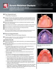
Maximizing Clinical Flexibility with<br />
Inclusive ® TRS Open Platform<br />
Dr. Tarun Agarwal<br />
Page 17<br />
Implant Considerations in the<br />
Esthetic Zone<br />
Dr. Siamak Abai<br />
Page 25<br />
Implant-Retained Overdenture:<br />
Diagnosis to Delivery<br />
Dr. David Little<br />
Page 39<br />
Restoring the Edentulous Maxilla<br />
Using CBCT Technology<br />
Dr. Timothy Kosinski<br />
Page 55<br />
COLUMNS<br />
Inclusive<br />
Restorative Driven Implant Solutions Vol. 4, Issue 1<br />
A Multimedia Publication of <strong>Glidewell</strong> Laboratories • www.inclusivemagazine.com<br />
‘My First Implant’<br />
From Russia with Love<br />
Dr. Russell Baer<br />
Recalls His<br />
First Implant Case<br />
Page 11<br />
Implant Q&A:<br />
Dr. Curtis Jansen<br />
Monterey, Calif.<br />
Page 47
Check out the latest issue of Inclusive<br />
magazine online or via your smartphone at<br />
www.inclusivemagazine.com<br />
– www.inclusivemagazine.com –<br />
On the Web<br />
Here’s a sneak peek at additional<br />
Inclusive magazine content available online<br />
ONLINE VIDEO PREsENtAtIONs<br />
■ <strong>Glidewell</strong> Laboratories Vice President of Sales and Business<br />
Development Dave Casper introduces Dr. Siamak Abai as the<br />
new editor-in-chief and clinical editor of Inclusive magazine.<br />
■ Dr. Siamak Abai summarizes the biological considerations critical to<br />
a predictable and esthetic result when placing and restoring dental<br />
implants in the anterior.<br />
■ Dzevad Ceranic, CDT, explains some of the clinical and financial<br />
advantages to prescribing a CAD/CAM milled bar in lieu of a conventional<br />
cast metal bar in implant denture cases.<br />
■ Dr. Curtis Jansen discusses the prevalence of single-tooth implant<br />
restorations, the significance of intraoral scanning, the practical and<br />
emotional benefits of all-inclusive pricing, the prospects of sameday<br />
dentistry, and risk management for implant treatment in an<br />
interview with contributing editor Dr. Bradley Bockhorst.<br />
■ Dr. Timothy Kosinski outlines the step-by-step process by which an<br />
edentulous arch can be safely and predictably restored via implant<br />
therapy utilizing the latest CBCT technology.<br />
■ <strong>Glidewell</strong> director of implant R&D and digital manufacturing Grant<br />
Bullis identifies the thread characteristics of dental implants and<br />
examines the mechanical forces exhibited by various thread forms.<br />
ONLINE CE CREDIt<br />
■ Get free CE credit for the material in this issue with each test you<br />
complete and pass. To get started, visit our website and look for<br />
the articles marked with “CE.”<br />
Look for these icons on the pages that follow<br />
for additional content available online
Contents<br />
17<br />
25<br />
39<br />
47<br />
Maximizing Clinical Flexibility with the Open<br />
Platform Inclusive Tooth Replacement Solution<br />
Dr. Tarun agarwal Designed around the clinician’s implant<br />
system of choice, the Open Platform Inclusive Tooth Replacement<br />
Solution provides the clinical flexibility to facilitate an esthetic,<br />
predictable outcome regardless of the chosen treatment protocol.<br />
In a demonstration of these principles, Dr. Tarun Agarwal presents<br />
a case in which he restores a mandibular first molar with the benefit<br />
of a CAD/CAM custom healing abutment and matching custom<br />
impression coping specifically designed for the prescribed Nobel<br />
Biocare implant.<br />
Implant Considerations in the Esthetic Zone<br />
Dr. siamak abai With increasing emphasis on ideal esthetic<br />
outcomes, clinicians require a firm understanding of the biological<br />
considerations needed to produce predictable results. Dr. Siamak Abai<br />
summarizes the peri-implant soft tissue, gingival biotype and other key<br />
characteristics clinicians should account for when treatment planning in<br />
the anterior. He further explains the vital role of proper implant placement,<br />
site preparation and a properly planned provisional in providing<br />
a successful esthetic and functional outcome.<br />
Implant-Retained Overdenture: Diagnosis to Delivery<br />
Dr. DaviD liTTle By providing superior stability, function and<br />
retention, implant-retained dentures are helping to address many<br />
of the challenges faced by edentulous patients. Dr. David Little<br />
explains the advantages of implant-retained prostheses before<br />
outlining a case from initial examination through final restoration.<br />
Along the way, he discusses the ins and outs of treatment planning,<br />
implant placement, impression-taking, try-ins, and the importance<br />
of teamwork and dental laboratories in restoring edentulous cases<br />
with implant therapy.<br />
Implant Q&A: An Interview with Dr. Curtis Jansen<br />
Dr. CurTis Jansen Digital advances are inevitably changing the<br />
way doctors approach restorative solutions. Dr. Curtis Jansen explores<br />
the evolving role of digital scanning, compares various intraoral<br />
scanners and weighs the advantages of same-day dentistry against<br />
traditional laboratory services. He also discusses the preeminence of<br />
single-unit restorations and first molars in implantology; explains the<br />
benefits of single, all-inclusive fees; and emphasizes the importance<br />
of managing risk and patient expectations.<br />
– Contents – 1
– www.inclusivemagazine.com –<br />
PuBLIshER<br />
Jim <strong>Glidewell</strong>, CDT<br />
EDItOR-IN-ChIEF, CLINICAL EDItOR<br />
Siamak Abai, DDS, MMedSc<br />
INCLusIVE MARkEtINg & EDuCAtION MANAgER<br />
Jennifer Archer<br />
MANAgINg EDItORs<br />
David Casper, Greg Minzenmayer<br />
CREAtIVE DIRECtOR<br />
Rachel Pacillas<br />
CONtRIButINg EDItORs<br />
Bradley C. Bockhorst, DMD; Grant Bullis;<br />
Dzevad Ceranic, CDT; Tim Torbenson;<br />
Keith Peters; Eldon Thompson; Barbara Young<br />
COPy EDItORs<br />
David Frickman, Jennifer Holstein,<br />
Chris Newcomb, Megan Strong<br />
DIgItAL MARkEtINg MANAgER<br />
Kevin Keithley<br />
gRAPhIC DEsIgNERs/WEB DEsIgNERs<br />
Emily Arata, Jamie Austin, Deb Evans, Juan Gallardo,<br />
Kevin Greene, Joel Guerra, Tony Hsiao,<br />
Audrey Kame, Allison Newell, Phil Nguyen,<br />
Kelley Pelton, Melanie Solis, Ty Tran, Makara You<br />
PhOtOgRAPhERs/VIDEOgRAPhERs<br />
Sharon Dowd, Mariela Lopez;<br />
Andrew Lee, James Kwasniewski, Marc Repaire,<br />
Sterling Wright, Maurice Wyble<br />
ILLustRAtOR<br />
Phil Nguyen<br />
COORDINAtORs/AD REPREsENtAtIVEs<br />
Teri Arthur, Vivian Tsang<br />
If you have questions, comments or suggestions, e-mail us at<br />
inclusivemagazine@glidewelldental.com. Your comments may be<br />
featured in an upcoming issue or on our website.<br />
© 2013 <strong>Glidewell</strong> Laboratories<br />
Neither Inclusive magazine nor any employees involved in its publication<br />
(“publisher”) makes any warranty, express or implied, or assumes any<br />
liability or responsibility for the accuracy, completeness, or usefulness of<br />
any information, apparatus, product, or process disclosed, or represents<br />
that its use would not infringe proprietary rights. Reference herein to<br />
any specific commercial products, process, or services by trade name,<br />
trademark, manufacturer or otherwise does not necessarily constitute<br />
or imply its endorsement, recommendation, or favoring by the publisher.<br />
The views and opinions of authors expressed herein do not necessarily<br />
state or reflect those of the publisher and shall not be used for advertising<br />
or product endorsement purposes. CAUTION: When viewing the<br />
techniques, procedures, theories and materials that are presented, you<br />
must make your own decisions about specific treatment for patients and<br />
exercise personal professional judgment regarding the need for further<br />
clinical testing or education and your own clinical expertise before trying<br />
to implement new procedures.<br />
Inclusive is a registered trademark of Inclusive <strong>Dental</strong> Solutions.
Contents<br />
ALSO IN THIS ISSUE<br />
8 Trends in Implant Dentistry<br />
Monolithic Implant Crowns<br />
11 My First Implant<br />
Dr. Russell Baer<br />
29 Small Diameter Implants<br />
Choosing the Appropriate<br />
Implant Diameter<br />
33 Lab Sense<br />
Raising the Bar: Inclusive CAD/CAM<br />
Milled Bar Technology<br />
45 Product Spotlight<br />
Inclusive TRS Screw-Retained<br />
Hybrid Denture<br />
65 R&D Corner<br />
Form and Function of Implant<br />
Threads in Cancellous Bone<br />
85 Clinical Tip<br />
Residual Cement Removal, Titanium<br />
Scalers and Successful Restorations<br />
55<br />
71<br />
75<br />
I Have a CBCT Scan — Now What Do I Do?<br />
Restoring the Edentulous Maxilla with <strong>Dental</strong> Implants<br />
Dr. TimoThy kosinski For clinicians entering the increasingly<br />
popular world of implant dentistry, a full understanding of the<br />
risks, benefits, limitations and anatomic considerations involved is<br />
crucial. To ensure the best result possible, dentists should visualize<br />
the completed restoration up front. Dr. Timothy Kosinski explains<br />
how modern technology is making surgical implant procedures<br />
more predictable and accessible, presenting an edentulous maxillary<br />
case that demonstrates how digital technology is simplifying the<br />
placement, positioning and angulation of implants, putting both<br />
doctors and patients at ease.<br />
Clinical Case Report: Maxillary Esthetic Zone<br />
Restoration with a Monolithic BruxZir Implant Bridge<br />
Dr. ara nazarian Modern dentistry continues to benefit from<br />
clinical advances, giving doctors the tools and materials needed to<br />
treat implant cases with a high degree of precision, customization and<br />
predictability. Dr. Ara Nazarian describes an anterior maxillary case<br />
that was treated with dental implants and a BruxZir Solid Zirconia<br />
bridge to effectively achieve a functional and esthetically pleasing<br />
result. In the process, he explains how monolithic restorations, the<br />
training of soft tissue with patient-specific provisionals and the<br />
precision of the CAD/CAM design process are setting up today’s<br />
implant cases for success.<br />
Use of Cone Beam Computed Tomography in<br />
Implant Dentistry: The ICOI Consensus Report<br />
Dr. erika benaviDes, eT al. In moving beyond the twodimensional<br />
limitations of conventional radiography, Cone Beam<br />
Computed Tomography (CBCT) is having a significant impact on<br />
implant dentistry. Its 3-D imaging offers dentists a powerful tool<br />
in the assessment, diagnosis and treatment planning of implant<br />
cases. Here, the International Congress of Oral Implantologists<br />
(ICOI) reports on the benefits and applications of CBCT scanning,<br />
explaining key aspects such as field of view, scan volume size,<br />
dose considerations and the advantages the technology brings to<br />
digital treatment planning, implant placement, surgical guidance,<br />
anatomical assessment and implant site evaluation.<br />
– Contents – 3
Contributors<br />
■ SIAMAK ABAI, DDS, MMedSc<br />
Dr. Siamak Abai earned his DDS degree from<br />
Columbia University in 2004, followed by two<br />
years of residency in general dentistry. After two<br />
years of general private practice in Huntington<br />
Beach, Calif., he returned to academia and<br />
received an MMedSc degree and a certificate<br />
in prosthodontics from Harvard University.<br />
Dr. Abai brings nearly 10 years of clinical, research and<br />
lecturing experience to his role as director of clinical research<br />
and development for <strong>Glidewell</strong> Laboratories’ Implant division.<br />
He is also editor-in-chief and clinical editor of Inclusive<br />
magazine. Before joining <strong>Glidewell</strong> in January 2012, Dr. Abai<br />
practiced at the Wöhrle <strong>Dental</strong> Implant Clinic in Newport Beach,<br />
Calif. Contact him at inclusivemagazine@glidewelldental.com.<br />
■ BRADLEY C. BOCKHORST, DMD<br />
After receiving his dental degree from Washington<br />
University School of <strong>Dental</strong> Medicine,<br />
Dr. Bradley Bockhorst served as a Navy <strong>Dental</strong><br />
Officer. Dr. Bockhorst is Director of Marketing,<br />
Restorative/Zfx for Zimmer <strong>Dental</strong>. He also<br />
maintains a private practice in Oceanside,<br />
Calif. A member of the CDA, ADA, AO, ICOI<br />
and the AAID, Dr. Bockhorst lectures internationally on an<br />
array of dental implant topics. In this issue of Inclusive magazine,<br />
Dr. Bockhorst serves as guest contributing editor for the<br />
Implant Q&A interview with Dr. Curtis Jansen. Contact him at<br />
760-929-4324 or bradley.bockhorst@zimmer.com.<br />
■ GRANT BULLIS, MBA<br />
Grant Bullis, director of implant R&D and digital<br />
manufacturing at <strong>Glidewell</strong> Laboratories,<br />
began his dental industry career at Steri-Oss<br />
(now a subsidiary of Nobel Biocare) in 1997.<br />
Since joining the lab in 2007, Grant has been<br />
integral in obtaining FDA 510(k) clearances<br />
for the company’s Inclusive ® Custom Implant<br />
Abutments. In 2010, he was promoted to director and now<br />
oversees all aspects of CAD/CAM, implant product development<br />
and manufacturing. Grant has a degree in mechanical<br />
CAD/CAM from Irvine Valley College and an MBA from<br />
Keller Graduate School of Management. Contact him at<br />
inclusivemagazine@glidewelldental.com.<br />
4<br />
– www.inclusivemagazine.com –<br />
■ DZEVAD CERANIC, CDT<br />
Dzevad Ceranic began his career at <strong>Glidewell</strong><br />
Laboratories while attending Pasadena<br />
City College’s dental laboratory technology<br />
program. In 1999, Dzevad began working at<br />
<strong>Glidewell</strong> as a waxer and metal finisher, then<br />
as a ceramist. He was then promoted to general<br />
manager of the Full-Cast department. In<br />
2008, Dzevad took on the company’s rapidly growing Implant<br />
department, and in 2009 completed an eight-month implants<br />
course at UCLA School of Dentistry. Today, Dzevad leads an<br />
implant team of more than 250 employees at the lab. Contact<br />
him at inclusivemagazine@glidewelldental.com.<br />
■ TARUN AGARWAL, DDS, PA<br />
Dr. Tarun Agarwal is a 1999 graduate of<br />
the University of Missouri-Kansas City. He<br />
maintains a full-time private practice emphasizing<br />
esthetic, restorative and implant<br />
dentistry in Raleigh, N.C., and regularly<br />
presents programs to study clubs and dental<br />
organizations nationally. Through his realworld<br />
approach to dentistry, practice enhancement and<br />
life balance, Dr. Agarwal seeks to motivate dentists and<br />
energize team members to increase productivity and profitability.<br />
His work and practice have been featured in<br />
numerous consumer and dental publications. Contact him at<br />
dra@raleighdentalarts.com or visit www.raleighdentalarts.com.<br />
■ RUSSELL A. BAER, DDS<br />
After teaching implant dentistry and conducting<br />
research in implantology and reconstructive<br />
dentistry at the University of Chicago,<br />
Dr. Russell Baer’s passion led him to the former<br />
Soviet Union, where he founded and serves<br />
as academic director of the Chicago Center<br />
for Advanced Dentistry. With offices in Moscow,<br />
Kiev, Vilnius, Almaty and Mumbai, this training center<br />
gives American dentists the opportunity to teach and practice<br />
implant dentistry abroad. Dr. Baer mentors general dentists on<br />
implantology and does clinical research at University Associates<br />
in Dentistry/<strong>Dental</strong> Implant Institute of Chicago. An active<br />
AO and ICOI member, he has written numerous articles and<br />
lectures worldwide. Contact him at rabaer@uadchicago.com.
■ ERIKA BENAVIDES, DDS, Ph.D<br />
Dr. Erika Benavides obtained her DDS at the<br />
University of Valle in Cali, Colombia, before<br />
completing a craniofacial genetics externship<br />
program at the Medical University of South Carolina<br />
and a GPR program at the University of<br />
Missouri Kansas City (UMKC) and the Truman<br />
Medical Center. At UMKC, she also received oral<br />
and maxillofacial radiology training and a Ph.D in oral biology<br />
and biomedical engineering. She is a clinical assistant professor<br />
at the University of Michigan School of Dentistry, a Diplomate<br />
of the American Board of Oral and Maxillofacial Radiology,<br />
and she holds dual appointments with the American Academy<br />
of Oral and Maxillofacial Radiology (AAOMR). Her faculty practice<br />
is dedicated to CBCT. Contact her at benavid@umich.edu.<br />
■ SCOTT D. GANZ, DMD<br />
After graduating from the University of Medicine<br />
and Dentistry of New Jersey, Dr. Scott<br />
Ganz completed a three-year specialty program<br />
in Maxillofacial Prosthetics at MD<br />
Anderson Cancer Center in Houston, Texas.<br />
His book, “An Illustrated Guide to Understanding<br />
<strong>Dental</strong> Implants,” has received wide<br />
acclaim as the standard in patient education texts, and has<br />
sold in more than 15 countries. Dr. Ganz has published more<br />
than 75 articles and has been the featured speaker for numerous<br />
organizations over the past 20 years, including the AO,<br />
ICOI and AAID, among others. Contact him at 201-592-8888<br />
or sdgimplant@aol.com.<br />
■ CURTIS E. JANSEN, DDS<br />
Dr. Curtis Jansen received his dental degree and<br />
a certificate in advanced education in prosthodontics<br />
at the University of Southern California<br />
(USC), where he went on to teach in the<br />
department of restorative dentistry and served<br />
as director of implant dentistry. He practiced<br />
and worked with a dental implant manufacturer<br />
in Florida and was extensively involved in the research,<br />
design and development of a number of patented implant restorative<br />
components used by major manufacturers today.<br />
Dr. Jansen lectures widely and owns a private prosthodontics<br />
practice in Monterey, Calif., with an on-site dental laboratory.<br />
Contact him at cejdds@mac.com or 831-656-9394.<br />
■ TIMOTHY F. KOSINSKI, DDS, MAGD<br />
Dr. Timothy Kosinski graduated from the University<br />
of Detroit Mercy School of Dentistry<br />
and received a Master of Science degree in biochemistry<br />
from Wayne State University School<br />
of Medicine. An adjunct assistant professor<br />
at UDM School of Dentistry, he serves on the<br />
editorial review board of numerous dental<br />
journals and is a Diplomate of the ABOI/ID, ICOI and AO.<br />
Dr. Kosinski is a Fellow of the AAID and received his Mastership<br />
in the AGD, from which he received the 2009 Lifelong Learning<br />
and Service Recognition award. Contact him at 248 -646-8651,<br />
drkosin@aol.com or www.smilecreator.net.<br />
■ DAVID A. LITTLE, DDS<br />
Dr. David Little received his DDS at the<br />
University of Texas Health Science Center<br />
at San Antonio <strong>Dental</strong> School and now<br />
maintains a multidisciplinary, state-of-the-art<br />
dental practice in San Antonio, Texas. An<br />
accomplished national and international<br />
speaker, professor and author, he also serves<br />
the dental profession as a clinical researcher, focusing on<br />
implants, laser surgery and dental materials. As a professional<br />
consultant, he shares his expertise on emerging restorative<br />
techniques and materials with industry peers. Highly respected<br />
for his proficiency in team motivation, Dr. Little’s vision,<br />
leadership and experience are recognized worldwide. Contact<br />
him at dlittledds@aol.com.<br />
■ MICHAEL McCRACKEN, DDS, Ph.D<br />
Dr. Michael McCracken is co-director of CIRP,<br />
a yearlong comprehensive implant education<br />
institute in Birmingham, Ala. After completing<br />
dental school at University of North Carolina<br />
at Chapel Hill and a prosthodontic residency<br />
at University of Alabama at Birmingham, he<br />
received a Ph.D in biomedical engineering.<br />
Dr. McCracken is a part-time professor at UAB, where he has<br />
served as associate dean for education, director of graduate<br />
prosthodontics and director of the implant training program.<br />
He maintains an active research program within the university<br />
and a private practice focused on implant dentistry. He also<br />
lectures internationally. Contact him at 256-797-1964.<br />
– Contributors – 5
Contributors<br />
■ ARA NAZARIAN, DDS, DICOI<br />
Dr. Ara Nazarian maintains a private practice<br />
in Troy, Mich., with an emphasis on<br />
comprehensive and restorative care. He is<br />
the director of the Reconstructive Dentistry<br />
Institute, a Diplomate of the ICOI, and has<br />
conducted lectures and hands-on workshops<br />
on esthetic materials and dental implants<br />
throughout the U.S., Europe, New Zealand and Australia.<br />
Dr. Nazarian is also the creator of the DemoDent patient education<br />
model system. His articles have been published in many<br />
popular dental publications. Contact him at 248-457-0500<br />
or www.aranazariandds.com.<br />
■ PARESH B. PATEL, DDS<br />
Dr. Paresh Patel is a graduate of the University<br />
of North Carolina at Chapel Hill School of<br />
Dentistry and the Medical College of Georgia/<br />
AAID MaxiCourse. He is cofounder of the<br />
American Academy of Small Diameter Implants<br />
and a clinical instructor at the Reconstructive<br />
Dentistry Institute. Dr. Patel has placed more<br />
than 2,500 small-diameter implants and has worked as a<br />
lecturer and clinical consultant on mini implants for various<br />
companies. He belongs to numerous dental organizations,<br />
including the ADA, North Carolina <strong>Dental</strong> Society and<br />
AACD. Dr. Patel is also a member and president of the Iredell<br />
County <strong>Dental</strong> Society in Mooresville, N.C. Contact him at<br />
pareshpateldds2@gmail.com or www.dentalminiimplant.com.<br />
■ HECTOR F. RIOS, DDS, Ph.D<br />
Dr. Hector Rios received his dental degree from<br />
the University of Valle in Cali, Columbia. He<br />
then completed a GPR program in hospital<br />
dentistry at the University of Missouri Kansas<br />
City (UMKC) and the Truman Medical Center.<br />
At UMKC, he also obtained a Ph.D in oral<br />
biology/molecular biology and biochemistry.<br />
Currently, he is a tenure-track assistant professor in the<br />
department of periodontics and oral medicine at the University<br />
of Michigan School of Dentistry in Ann Arbor, and a Diplomate<br />
of the American Board of Periodontology. Dr. Rios maintains<br />
a faculty practice limited to periodontics and dental implants.<br />
Contact him at hrios@umich.edu.<br />
6<br />
– www.inclusivemagazine.com –<br />
■ SUSAN S. WINGROVE, RDH<br />
Susan Wingrove is an international speaker<br />
and practicing dental hygienist, who does<br />
regeneration research as a consultant for<br />
Regena Therapeutics and instrument design<br />
for Paradise <strong>Dental</strong> Technologies Inc. She<br />
designed the Wingrove Titanium Implant Set,<br />
ACE probes and Queen of Hearts instruments.<br />
A member of the AO, American <strong>Dental</strong> Hygiene Association<br />
and International Federation of <strong>Dental</strong> Hygiene, she is also<br />
a published author who has written articles for national and<br />
international journals on implant therapy, regeneration and<br />
advanced instrumentation, as well as the textbook “Peri-<br />
Implant Therapy for the <strong>Dental</strong> Hygienist: Clinical Guide to<br />
Maintenance and Disease Complications” (Wiley-Blackwell).<br />
Contact her at sswinrdh@gmail.com.<br />
■ TIM TORBENSON<br />
Tim Torbenson has more than three decades<br />
of dental industry experience in the technical,<br />
restorative and surgical aspects of the<br />
field. Since 1986, Tim has been exclusively<br />
involved in implant dentistry, working<br />
in dental laboratories and with dental<br />
implant manufacturers on implant product<br />
development, education and training program development,<br />
management and technical support. He has also lectured<br />
throughout the U.S. on various dental implant-related<br />
topics. Tim joined <strong>Glidewell</strong> in August 2011 as director of<br />
implant sales and business development. Contact him at<br />
inclusivemagazine@glidewelldental.com.
Letter from the Editor<br />
<strong>Glidewell</strong> Laboratories has ushered in the new year with many advances in<br />
restorative materials and prosthetic dentistry, as well as a new editor-in-chief of<br />
Inclusive magazine. Since joining the <strong>Glidewell</strong> clinical research and development<br />
team over a year ago, I feel welcomed to be a part of this quarterly publication.<br />
After finishing my prosthodontics residency in Boston, Mass., I joined the private<br />
practice of world-renowned Dr. Peter Wöhrle in Newport Beach, Calif. My<br />
journey in dentistry led me to <strong>Glidewell</strong> Laboratories, where I’ve been able to<br />
accentuate my clinical and research training to provide colleagues with thoughtprovoking<br />
articles and information about clinical advances made possible by the<br />
latest dental technology.<br />
In this issue of Inclusive magazine, Dr. Russell Baer details his experiences abroad<br />
as he recounts placing his first implant in Moscow, Russia, almost two decades<br />
ago. His international efforts led to the establishment of implant training programs<br />
in Russia, Kazakhstan and India, among other countries. Garnering international<br />
attention and drawing some of the biggest names in implant dentistry, these<br />
thriving programs continue to enhance the lives of patients around the globe.<br />
The benefits of providing a complete solution to the patient from the treatment<br />
planning phase to the final restoration is highlighted in Dr. Tarun Agarwal’s<br />
article “Maximizing Clinical Flexibility with the Open Platform Inclusive Tooth<br />
Replacement Solution.” Under this treatment option, the concept of complete<br />
patient care is combined with a predictable fee schedule and custom tissue<br />
contouring, resulting in consistent treatment and improved case acceptance.<br />
Articles by Dr. David Little and Dr. Timothy Kosinski highlight the use of technology<br />
in implant prosthodontics, with an emphasis toward improving the standard of<br />
care through the use of cone beam computed tomography and digital treatment<br />
planning. Dr. Kosinski highlights the use of digital technology for the treatment<br />
planning of implant-retained overdentures in the maxillary arch, while Dr. Little<br />
guides us through a mandibular implant-retained overdenture case.<br />
Running throughout this issue is a common theme of utilizing the latest technology<br />
in patient treatment. <strong>Dental</strong> technology has come a long way in recent<br />
years, and now it is our responsibility as clinicians to maximize its use to raise<br />
the quality of patient treatment. An interview with Dr. Curtis Jansen detailing his<br />
experiences with intraoral scanning and CAD/CAM-produced restorations highlights<br />
this concept.<br />
I look forward to being a part of your journey in prosthodontics and implant<br />
dentistry.<br />
With kind regards,<br />
Dr. Siamak Abai<br />
Editor-in-Chief, Clinical Editor<br />
inclusivemagazine@glidewelldental.com<br />
– Letter from the Editor – 7
Trends in<br />
Implant Dentistry<br />
In 2012, <strong>Glidewell</strong> Laboratories saw continued growth in the demand for BruxZir ® Solid Zirconia<br />
crowns, which by year’s end surpassed PFMs as the implant restoration of choice. With no porcelain<br />
overlay, monolithic all-ceramic restorations produced from BruxZir zirconia or IPS e.max ® lithium<br />
disilicate (Ivoclar Vivadent; Amherst, N.Y.) have exhibited the ability to better withstand functional<br />
stresses that can result in chipping. The flexural strength of BruxZir Solid Zirconia is significantly<br />
greater than that of a conventional PFM, 1 while its high fracture toughness (KIc value) reflects the<br />
material’s ability to absorb the energy responsible for crack propagation three to six times better than<br />
traditional ceramics. 2,3 Doctors are taking notice, leading to a significant rise in all-ceramic prescriptions<br />
while the demand for coping-based restorations remains flat in comparison.<br />
8<br />
Sales of Implant Crowns at <strong>Glidewell</strong> Laboratories<br />
January 2012–December 2012<br />
BruxZir ® Solid Zirconia IPS e.max ®<br />
4,000<br />
3,000<br />
2,000<br />
1,000<br />
0<br />
Monolithic Implant Crowns<br />
Coping-Based All-Ceramic<br />
PFM<br />
Jan-12 Feb-12 Mar-12 Apr-12 May-12 Jun-12<br />
Data source: <strong>Glidewell</strong> Laboratories January 2011–December 2012<br />
REFERENCES<br />
1. Guess PC, Att W, Strub JR. Zirconia in fixed implant prosthodontics. Clin Implant Dent Relat Res. 2012 Oct;14(5):633-45.<br />
2. Chiang YT, Birnie D, Kingery WD. Physical ceramics: principles for ceramics science and engineering. John Wiley & Sons. 1997:484.<br />
3. Griffiths AA. The phenomena of rupture and flow in solids. Philosophical Transactions of the Royal Society of London 1920. Series A(221):163-98.<br />
– www.inclusivemagazine.com –
Year-Over-Year Total Sales Increase for<br />
BruxZir Implant Crowns<br />
Clinicians who have switched from PFMs to monolithic all-ceramic restorations<br />
are seeing considerable benefits, including exceptional resistance to<br />
chipping and fracture. At the same time, the precision and predictability<br />
of the CAD/CAM manufacturing process is improving patient acceptance<br />
upon initial seating. This is inspiring increased confidence among clinicians<br />
in the immediate and long-term success of their implant restorations.<br />
– Dzevad Ceranic, CDT<br />
Implant Department General Manager<br />
Jul-12 Aug-12 Sep-12 Oct-12 Nov-12 Dec-12<br />
Watch here for emerging trends<br />
Check back here for more observations in the next issue.<br />
– Trends in Implant Dentistry: Monolithic Implant Crowns – 9
my first<br />
implant<br />
with Russell A. Baer, DDS<br />
thERE WAs A CERtAIN gLAMOuR to the idea of traveling to<br />
a faraway place like Moscow, replete with caviar, vodka,<br />
beautiful women and characters from the Russian<br />
underworld. What started out as a handful of people<br />
going overseas on a regular basis to teach implant<br />
technology in a government-run polyclinic evolved into<br />
a comprehensive teaching and training program that<br />
drew big names in the dental world. Decades later, the<br />
program is still going strong and has spread to the far<br />
corners of the globe. Dr. Russell Baer shares his story with<br />
Inclusive magazine.<br />
FROM RUSSIA WITH LOVE<br />
I fell into dentistry almost by accident. As a cardiopulmonary<br />
technician, I enjoyed my work in an intensive care unit<br />
and was bound for medical school. But after watching doctors<br />
come to the hospital at all hours of the night, half of<br />
them with failing marriages, I reconsidered my career path<br />
and chose to go to dental school. I still loved the exposure<br />
to surgery, which would be advantageous years later when<br />
I began placing implants.<br />
I graduated from dental school and completed my general<br />
practice residency in the mid-1980s. I went through restorative<br />
training and implants with Danny Sullivan and Steve<br />
Perells. At that time we practiced in a classic model at the<br />
University of Chicago. In 1993, I had the opportunity to give<br />
some lectures in the former Soviet Union and Uzbekistan.<br />
Even though Moscow is only a two-hour flight from Sweden,<br />
they had not had anyone come and speak on modern<br />
implants since Leonard Linkow back in the late 1970s and<br />
early 1980s. This was a great opportunity. So I put together<br />
a training course: we would train the students, do several<br />
cases, then come back and deliver the final restorations<br />
a few months later. Slowly, we turned it over to the local<br />
doctors to teach. I went over for the first time in 1995 to<br />
teach the course and returned every 8 to 12 weeks. I took<br />
a good friend, oral surgeon Rick Balcerak, who performed<br />
the surgeries while I did the restorative work.<br />
ESTABLISHING OUR OWN PRIVATE CLINIC<br />
We encountered our share of challenges initially. We had<br />
to go to a different clinic each time because our local<br />
– My First Implant: Dr. Russell Baer –<br />
doctors were unreliable and never followed through. We<br />
had trouble keeping long-term relationships because they<br />
did not want to teach anyone else, and preferred instead to<br />
remain the local experts. Finally, in 1998, we decided to start<br />
our own clinic in order to establish better follow-through.<br />
We opened a private clinic called the Chicago Center for<br />
Advanced Dentistry, which was set along the main drag<br />
in Moscow near the Kremlin, on Tverskaya — the<br />
Rodeo Drive of that area.<br />
MY VERY FIRST IMPLANT (MOSCOW)<br />
Just before opening our private clinic, when we<br />
were still working in the government clinics, Rick<br />
turned to me and said: “I’m tired of this. You know<br />
what you’re doing. You place the implants.” I had<br />
watched enough surgeries and restored hundreds of<br />
cases up to this point, and it was time to start placing<br />
the implants myself. And with his mentorship,<br />
I did. It was a healed tooth #30 — I had observed<br />
hundreds of these — and I thought,<br />
“I can do it.” Pushing the<br />
lump in my throat aside, I<br />
followed what I had seen to<br />
the letter; I just went in there<br />
and did it. That night, all I<br />
could think of was the implant<br />
falling out of the<br />
patient’s mouth. But<br />
I saw that it worked,<br />
and it elevated my<br />
confidence level. That<br />
first implant solidified<br />
my love of surgery.<br />
After that I had many<br />
opportunities with<br />
our Russian patients<br />
— at times<br />
we would do 50<br />
to 60 procedures<br />
in a<br />
day — and<br />
I got better<br />
and better.
BRINGING IN THE BIG GUNS<br />
Because there was a certain glamorous appeal to a place<br />
like Russia — the vodka, the pretty women, venturing into<br />
new, uncharted waters — it was surprisingly easy to get<br />
fellow doctors to go over to Moscow with me. I brought<br />
some of the biggest names in dentistry at the time: Chuck<br />
Babbush, Paulo Malo, Jean Bedard, Jack Hahn and numerous<br />
others who continued to come over and teach. I was able to<br />
learn from their expertise, and it basically became my own<br />
private implant residency. Jack Hahn was a mentor to me<br />
and influenced the design of my residency. We also offered<br />
every specialty in dentistry and conducted several courses<br />
simultaneously. We might bring in an oral surgeon and do<br />
six or seven sinus lifts on a given weekend, for example,<br />
which was a fantastic way to learn.<br />
A DAY IN THE LIFE<br />
Here was my typical routine: Wednesday after work at the<br />
office here in Chicago, I would board a plane, land in Moscow,<br />
treat patients Thursday afternoon, Friday and Saturday,<br />
teach Saturday evening study club, and then be back home<br />
in Chicago on Sunday by 3:30 p.m. I did that about every<br />
eight weeks.<br />
In Moscow, our day usually started at 9 a.m. and went to<br />
about 9 p.m. We would have a big lunch and a late dinner,<br />
which is more of a European model. In the early days, when<br />
we were teaching in the government clinic, it was normal<br />
to take a big lunch and have borscht, blini and caviar, and<br />
shashlik — a kind of kebab. And it was not unusual for the<br />
doctors to want to do a vodka toast. The hardest thing was<br />
trying to be polite while turning them down, so I said no in<br />
the daytime but imbibed in the evenings so as not to insult<br />
our local partners.<br />
Interestingly, dentistry was able to break away from the<br />
government-run polyclinics, and private clinics started<br />
springing up. These were some of the most modern and<br />
luxurious clinics in the world, owned by organizations like<br />
Gazprom, a massive natural gas conglomerate in Russia.<br />
12<br />
– www.inclusivemagazine.com –<br />
Baer’s colleague and mentor, Jack Hahn (middle), poses with former students in<br />
2010 at the Chicago Center for Advanced Dentistry in Moscow. Renowned implantologist<br />
Sergey Zorin (left) is now one of the local doctors teaching in the program.<br />
They had digital X-rays, lasers and CEREC ® machines<br />
(Sirona <strong>Dental</strong> Systems; Charlotte, N.C.) in every operatory,<br />
as if money was no object. Some of these clinics were<br />
just amazing to me. My first introduction to CEREC was<br />
actually in Russia in the mid-1990s. We even ran into a<br />
machine that was like CEREC but would take the tooth<br />
out, scan it and mill an implant the exact same size as the<br />
root. At the time, it was considered a crazy invention, and<br />
it wasn’t widely accepted back in the States.<br />
We didn’t necessarily have more freedom to experiment in<br />
Moscow. We were very straightforward in our approach,<br />
since it was a difficult environment. We were always careful<br />
about pushing the envelope with immediate placement,<br />
immediate loading and function. We were conservative and<br />
wanted to get good results. Yet every time I left, I wondered<br />
if there would be a mob guy waiting for me at the airport<br />
saying, “I don’t like my implant.” Occasionally when a<br />
patient drove up in a black Mercedes with multiple escort<br />
cars, we were a bit leery, as it was not crystal clear whether<br />
they were part of the Russian underworld or government<br />
officials. I remember one patient who, excusing himself<br />
mid-procedure, stepped outside to have a cigarette with his<br />
bodyguard in the middle of having his full lower jaw done!<br />
ONCE UPON A TIME IN MUMBAI<br />
The Chicago Center for Advanced Dentistry was a premiere,<br />
high-end, private-style clinic that we started in Moscow.<br />
But the concept worked so well that we soon expanded<br />
into new areas of the region like Vilnius, Lithuania; Kiev,<br />
Ukraine; and then Almaty, Kazakhstan — which is where I<br />
spent Memorial Day this year placing implants.<br />
We also opened a clinic in Mumbai in 2004 or 2005. I was<br />
there, actually, about six months ago. We had a young<br />
dentist there from Iowa whom we hired out of college in<br />
1999. He also majored in Russian, so we hired him to live in<br />
Moscow and manage the clinic. And he is still managing the<br />
clinic today, but now commutes to Moscow from Mumbai<br />
since marrying a fellow Indian dentist.
In Mumbai, dentistry was more of a public health issue.<br />
The dentists all spoke English and had the technology;<br />
they just needed to convince the patients to take advantage<br />
of this technique.<br />
BACK IN THE USSR<br />
In Russia, on the other hand, you had a growing middle class,<br />
and the patients were eager for treatment. The majority of<br />
the patients we saw were people who had failing full-mouth<br />
dentition, and they weren’t going to tolerate dentures, so<br />
we did a lot of full-arch implant cases. Today, if you were to<br />
ask the big companies like Nobel Biocare and Straumann,<br />
they’d tell you that Russia is one of the fastest growing<br />
implant markets in the world.<br />
From the beginning and throughout the years, we had<br />
corporate partners who helped us supply the facility with<br />
equipment. We had to do some pitching, of course. When<br />
we first went over, we didn’t have any strong partners. We<br />
were using two lines of Stryker brand implants that no<br />
longer exist. Stryker had an implant division back then. We<br />
were also placing a screw-type implant that was eventually<br />
bought out by BioHorizons, and a fin-type implant, which<br />
is now the Bicon implant. I got to know Jack when we<br />
approached Steri-Oss in 1997, and he was the designer<br />
of their Replace implant (Nobel Biocare; Zurich,<br />
Switzerland). Russia was an emerging market, so<br />
what we were doing in Moscow was of interest<br />
to these companies.<br />
Back at home in Chicago, I knew that if it<br />
worked in Russia, it could also work here. But<br />
the bottom line is this: It’s not so much the<br />
implant that matters, but the person who is<br />
putting it in. The education and qualification<br />
of the doctor will always be primary, and the<br />
products secondary. IM<br />
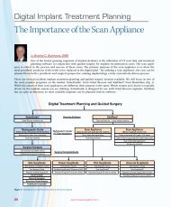
Title of article<br />
Left: Baer with business partner Mridu Sekar (left)<br />
and colleague Paulo Malo (middle) in Yalta, hosting<br />
a symposium sponsored by the Chicago Center for<br />
Advanced Dentistry<br />
Right: Baer featured on a billboard in Almaty,<br />
Kazakhstan<br />
Keeping it ReaL — Similar to the<br />
appeal that drew some of the big names<br />
in dentistry, there was a kind of celebrity<br />
attached to it all. At one point, my wife and<br />
I were traveling in Kazakhstan. Walking<br />
down the streets of Almaty, I said, “Honey,<br />
look.” And there was my face, larger than<br />
life, pasted across a billboard. But with the<br />
cars roaring by and people going about<br />
their busy days, she looked right past it<br />
and continued walking, unfazed,<br />
and said, “What?”
16<br />
– www.inclusivemagazine.com –
Maximizing Clinical Flexibility with the<br />
Open Platform Inclusive ®<br />
Tooth Replacement Solution<br />
by<br />
OsseoSpeed TX<br />
(DENTSPLY Implants)<br />
Tarun Agarwal, DDS, PA<br />
The Inclusive ® Tooth Replacement Solution is touted<br />
as the industry’s first all-in-one, restorative-driven<br />
treatment package, described in simplest terms<br />
as the complete set of components required to replace<br />
a missing tooth. But the true value of this full-service,<br />
patient-specific solution cannot be adequately measured<br />
with a mere list of parts and pieces, no matter how<br />
comprehensive that list may be. The ultimate benefit can<br />
instead be found in the freedom and flexibility inherent in<br />
the solution during all phases of treatment, which serve<br />
to maximize clinical efficiency and facilitate a predictable,<br />
esthetic outcome.<br />
Showcasing the most obvious example of this clinical<br />
flexibility is the Open Platform Inclusive Tooth Replacement<br />
Solution. While the original Inclusive Tooth Replacement<br />
Solution features an internal hex tapered implant of timetested<br />
design, the Open Platform treatment package is<br />
built around the clinician’s implant of choice. A clinician<br />
accustomed to working with any of the major implant<br />
OSSEOTITE ® Certain ®<br />
Tapered <strong>Dental</strong> Implant<br />
(Biomet 3i)<br />
Brånemark System ®<br />
(Nobel Biocare)<br />
NobelActive <br />
(Nobel Biocare)<br />
systems (Fig. 1) can therefore take full advantage of the<br />
Inclusive Tooth Replacement Solution prosthetic guide,<br />
custom temporary components, custom impression coping<br />
and final CAD/CAM restoration while placing an implant<br />
from his existing inventory.<br />
Whichever implant is used, the principal advantages to be<br />
found in utilizing the Inclusive Tooth Replacement Solution<br />
remain unchanged. With a stent to help direct implant<br />
placement from a prosthetic perspective, custom temporary<br />
components to provide contoured soft tissue management<br />
in the event of immediate provisionalization or conventional<br />
healing and a custom impression coping to fully capture the<br />
resulting gingival contours, the patient is better prepared<br />
to receive the accompanying final restoration with minimal<br />
discomfort and fewer adjustments. By truly beginning with<br />
the end result in mind, the Inclusive Tooth Replacement<br />
Solution streamlines the treatment workflow and alleviates<br />
component and communication issues too often associated<br />
with traditional implant services.<br />
NobelReplace ®<br />
Tapered Groovy ®<br />
(Nobel Biocare)<br />
Bone Level<br />
(Straumann USA, LLC)<br />
Go online for<br />
in-depth content<br />
Tapered<br />
Screw-Vent ®<br />
(Zimmer <strong>Dental</strong>)<br />
Figure 1: The Open Platform Inclusive Tooth Replacement Solution supports the following implant systems: Astra Tech OsseoSpeed (now DENTSPLY Astra Tech Implant<br />
System ); Biomet 3i Certain ® ; Nobel Biocare Brånemark System ® , NobelActive and NobelReplace ® ; Straumann Bone Level; and Zimmer Screw-Vent ® . All associated<br />
third-party trademarks are the property of their respective owners.<br />
– Maximizing Clinical Flexibility with the Open Platform Inclusive Tooth Replacement Solution – 17
Maximizing Clinical Flexibility with the Open Platform Inclusive Tooth Replacement Solution<br />
Figure 2: Rx form for the Open Platform Inclusive Tooth Replacement<br />
Solution<br />
Figure 4: A prosthetic guide featured with the Open<br />
Platform Inclusive Tooth Replacement Solution<br />
Flexibility in All Phases<br />
To better examine the Open Platform Inclusive Tooth<br />
Replacement Solution and the options it affords clinicians<br />
during each stage of treatment, it is helpful to break the<br />
package down into four distinct phases.<br />
Phase 1: Treatment Planning<br />
When submitting an Open Platform Inclusive Tooth<br />
Replacement Solution case, clinicians may take either<br />
digital or conventional full-arch impressions, along with<br />
a bite registration, so that the laboratory may accurately<br />
produce articulated study models. The special Rx enables<br />
clinicians to denote the system, diameter and platform<br />
size of the implant to be used, along with the prescribed<br />
tooth shade and soft tissue depth noted in the edentulous<br />
site (Fig. 2). This information enables the laboratory to<br />
properly design custom components with patient-specific<br />
18<br />
– www.inclusivemagazine.com –<br />
Figure 3: Radiograph of an MIS SEVEN ® implant (MIS Implant Technologies;<br />
Fair Lawn, N.J.) placed using the Open Platform Inclusive Tooth Replacement<br />
Solution<br />
Figure 5: A custom healing abutment featured with the Open Platform<br />
Inclusive Tooth Replacement Solution<br />
soft-tissue contours in an effort to provide a more natural<br />
emergence profile than that obtained with conventional<br />
stock components.<br />
Phase 2: Surgical<br />
Courtesy of Robert A. Horowitz, DDS<br />
Placement of the prescribed implant is performed<br />
according to clinician preference, using the system and<br />
instrumentation of choice (Fig. 3). Because implant placement<br />
within the edentulous space is critical to achieving an<br />
optimal restorative outcome, the Open Platform Inclusive<br />
Tooth Replacement Solution features a prosthetic guide<br />
(Fig. 4) with which to prepare the osteotomy in freehand<br />
cases. Anatomical landmarks should be properly accounted<br />
for during treatment planning, as the prosthetic guide does<br />
not take these into consideration. However, use of the guide<br />
will ensure swift, accurate seating of the custom healing
Figure 6: A custom temporary abutment and BioTemps provisional crown<br />
featured with the Open Platform Inclusive Tooth Replacement Solution<br />
Figure 8: Anatomical sulcus following custom healing phase of the Open<br />
Platform Inclusive Tooth Replacement Solution<br />
abutment or custom temporary abutment, and help to<br />
improve the final prosthetic outcome.<br />
Phase 3: Temporization/Healing<br />
Immediately upon implant placement, the clinician may<br />
elect to place the custom healing abutment (Fig. 5) or<br />
provisionalize the case with the custom temporary abutment<br />
and BioTemps ® provisional crown (Fig. 6). Temporization can<br />
also be performed after a period of healing, if indicated. The<br />
custom healing abutment and custom temporary abutment<br />
are each milled from a radiopaque, biocompatible polyether<br />
ether ketone (PEEK) material that is easy to adjust as<br />
needed, while the BioTemps crown milled from poly(methyl<br />
methacrylate) (PMMA) is designed with an internal relief<br />
space to allow for adjustable seating during cementation.<br />
The custom temporary abutment and BioTemps crown<br />
can even be modified and luted together extraorally to<br />
Figure 7: A custom impression coping featured with the Open Platform<br />
Inclusive Tooth Replacement Solution<br />
Figure 9: Inclusive Custom Abutments are available in titanium, all-zirconia<br />
or zirconia with titanium base<br />
create a single-piece screw-retained provisional. Whatever<br />
the indication or preference, patient-specific soft tissue<br />
management can be initiated upon implant placement — in<br />
a fraction of the time it would require to create a custom<br />
component chairside.<br />
Phase 4: Final Restoration<br />
When the time comes for the definitive restoration, a final<br />
impression is taken with the custom impression coping<br />
(Fig. 7). This CAD/CAM component is designed with the<br />
same gingival contours as the custom healing abutment and<br />
custom temporary abutment to precisely capture the final<br />
gingival architecture (Fig. 8) and convey that information<br />
to the laboratory, providing a greater understanding of the<br />
appropriate emergence profile. Along with final full-arch<br />
impressions, the clinician submits a final Rx for the desired<br />
Inclusive ® Custom Abutment (Fig. 9) and final BruxZir ®<br />
– Maximizing Clinical Flexibility with the Open Platform Inclusive Tooth Replacement Solution – 19
Maximizing Clinical Flexibility with the Open Platform Inclusive Tooth Replacement Solution<br />
Figure 10: Clinicians may prescribe a final crown made from BruxZir Solid<br />
Zirconia or IPS e.max<br />
Figure 12: Radiograph of tooth #19 after endodontic therapy to treat periapical<br />
abscess<br />
Solid Zirconia or IPS e.max ® (Ivoclar Vivadent; Amherst,<br />
N.Y.) monolithic crown (Fig. 10). A screw-retained final<br />
restoration may also be prescribed (Fig. 11). The precise<br />
nature of the manufacturing process used to produce<br />
both the temporary and final custom components helps<br />
to ensure efficient seating of the definitive restoration<br />
upon final delivery, without blanching and with little to no<br />
chairside adjustment.<br />
Clinical Example<br />
The following case report serves to showcase the<br />
advantages and flexibility of the Open Platform Inclusive<br />
20<br />
Figure 11: A BruxZir Solid Zirconia screw-retained crown prescribed as<br />
the final restoration in a case utilizing the Open Platform Inclusive Tooth<br />
Replacement Solution<br />
Figure 13: Periapical radiograph of site #19 post-extraction<br />
Tooth Replacement Solution. This particular case features<br />
placement of a NobelActive implant from Nobel Biocare.<br />
Case Report<br />
– www.inclusivemagazine.com –<br />
Courtesy of Robert A. Horowitz, DDS<br />
Following endodontic therapy to treat a periapical abscess<br />
on tooth #19 (Fig. 12), the patient in this case suffered<br />
recurrent periapical infection requiring extraction of the<br />
compromised mandibular first molar. The patient was<br />
referred to an oral surgeon for drainage and extraction<br />
(Fig. 13), at which time immediate implant placement was<br />
contraindicated by the infection.
Figure 14: Radiograph of NobelActive implant placed in edentulous site #19 Figure 15: Digital design of custom healing abutment<br />
Figure 16: Digital design of custom impression coping Figure 17: Milled custom impression coping (left) with custom healing<br />
abutment (right)<br />
A five-month healing period was observed, after which<br />
the patient returned for diagnostic evaluation for implant<br />
therapy. A 3-D cone beam computed tomography (CBCT)<br />
scan was obtained using a GALILEOS scanner (Sirona<br />
<strong>Dental</strong> Systems; Charlotte, N.C.). The treatment plan called<br />
for guided placement of an 11.5 mm NobelActive RP implant<br />
in the edentulous space, utilizing all-digital impressions and<br />
a two-stage surgical protocol.<br />
After guided placement of the NobelActive implant (Fig. 14),<br />
an Inclusive ® Scanning Abutment for NobelActive RP was<br />
attached to the implant fixture for the purpose of capturing<br />
the precise location, angulation and connection orientation<br />
of the implant during the intraoral scan. A digital impression<br />
was taken using the CEREC ® Omnicam (Sirona <strong>Dental</strong><br />
Systems), and the information submitted to <strong>Glidewell</strong><br />
Laboratories for the CAD/CAM production of the custom<br />
healing abutment and custom impression coping featured<br />
with the Open Platform Inclusive Tooth Replacement<br />
Solution (Figs. 15–17).<br />
Following a prescribed healing period, the patient returned for<br />
a second-stage procedure involving exposure of the implant<br />
platform (Figs. 18a, 18b). To account for the shifting of adjacent<br />
teeth during osseointegration, a second digital impression<br />
was taken during this visit, this time utilizing the custom<br />
impression coping (Fig. 19). Use of this custom impression<br />
coping facilitates capture of the patient-specific gingival<br />
– Maximizing Clinical Flexibility with the Open Platform Inclusive Tooth Replacement Solution – 21
Maximizing Clinical Flexibility with the Open Platform Inclusive Tooth Replacement Solution<br />
Figure 18a: Presentation of edentulous site post-implant placement, following<br />
prescribed healing period<br />
Figure 19: Radiograph to confirm seating of custom impression coping<br />
contours. Once the digital impression was taken (Fig. 20),<br />
the custom healing abutment was placed (Figs. 21a–21c).<br />
Key advantages of the custom healing abutment include the<br />
preservation of keratinized soft tissue and preparation of<br />
that tissue into an ideal form for a more esthetic restoration,<br />
as well as simplified delivery of the definitive restoration.<br />
Having the abutment on hand eliminates tedious creation of<br />
a custom healing abutment chairside.<br />
For the definitive restoration, an IPS e.max screw-retained<br />
crown (Fig. 22) was prescribed and delivered. Due to<br />
Figure 18b: Second-stage exposure of the NobelActive implant platform<br />
Figure 20: Digital impression with custom component in place<br />
Figure 21a: Seating of custom healing abutment Figure 21b: Radiograph to confirm seating of custom healing abutment<br />
22<br />
– www.inclusivemagazine.com –<br />
proper preparation of the site utilizing the custom healing<br />
abutment (Figs. 23a, 23b), the accurate capture of that soft<br />
tissue architecture and the precise nature of the digital<br />
process, the crown seated easily into place. No adjustment<br />
was required.<br />
The use of a custom healing abutment and matching<br />
custom impression coping, combined with the use of digital<br />
impression technology, enabled this case to be completed<br />
in fewer visits, simplified delivery of the final prosthesis<br />
and resulted in a highly esthetic outcome. Both the patient
Figure 21c: Soft tissue sutured into place around custom healing abutment<br />
Figure 23a: Presentation of edentulous site #19 following prescribed healing<br />
period with custom healing abutment<br />
and the practice saved time and money. Given the minimal<br />
cost differential between custom components and generic<br />
ones, an open, patient-specific solution warrants strong<br />
consideration in the planning of any implant treatment<br />
modality.<br />
Summary<br />
Advancements in the techniques and materials associated<br />
with dental implant therapy have served to widen the range<br />
of treatment protocols available to practicing clinicians.<br />
Successfully managing these protocols and the options that<br />
may arise during any individualized procedure can go a long<br />
way toward determining the efficiency and predictability<br />
with which a case is completed. Undue reliance on traditional<br />
components can restrict a clinician’s choices during the<br />
course of treatment or require time-consuming chairside<br />
alternatives to avoid compromised results. The Open<br />
Platform Inclusive Tooth Replacement Solution is designed<br />
to meet this challenge by providing the flexibility needed<br />
to address any clinical situation, in whatever manner the<br />
Figure 22: IPS e.max screw-retained crown<br />
Figure 23b: Presentation of anatomically sculpted soft tissue at edentulous<br />
site #19 following removal of custom healing abutment<br />
clinician feels most comfortable or productive. Beginning<br />
with the implant of choice, those utilizing this solution may<br />
employ a single-stage or two-stage surgical protocol, provide<br />
patient-specific healing or custom provisionalization, take<br />
conventional or digital impressions, and select a definitive<br />
abutment and crown as indicated. Whatever the prescribed<br />
procedure, this adaptable, comprehensive solution aims to<br />
maximize clinical control during every phase of treatment,<br />
resulting in a simplified workflow that reduces chairtime<br />
while contributing to a more esthetic restoration. IM<br />
– Maximizing Clinical Flexibility with the Open Platform Inclusive Tooth Replacement Solution – 23
IMPLANT CONSIDERATIONS<br />
IN THE EsthEtIC ZONE<br />
by<br />
Siamak Abai, DDS, MMedSc<br />
Go online for<br />
in-depth content<br />
Successful clinical outcomes for implant placement and integration in the esthetic zone is multifactorial, with the clinician’s<br />
understanding of biological structures and implant biomaterials at the pinnacle of a qualified result. Through<br />
the years, there has been a shift in case outcome acceptance from mere satisfaction with the clinician’s placement<br />
of an implant regardless of position and esthetic result to rejection when there is deviation from the ideal esthetic<br />
outcome. This shift is a result of an increase in the clinician’s knowledge of the biological structures and implant site<br />
preparation prior to implant placement. Regardless of the physical position of the implant, biological considerations such<br />
as gingival biotype, an understanding of the peri-implant soft tissue, and the possibility of immediate implant placement<br />
and provisionalization have to be considered for a predictable outcome. With the advanced tools and technologies available<br />
today, clinicians who take the time to properly assess all relevant restorative factors prior to implant surgery will<br />
find it much easier to achieve an efficient, satisfying result.<br />
– Implant Considerations in the Esthetic Zone – 25
IMPLANT CONSIDERATIONS IN THE ESTHETIC ZONE<br />
Biological Considerations<br />
The predictability of ideal peri-implant<br />
tissue contour involves a number of<br />
clinical parameters and is ultimately<br />
determined by proper implant placement,<br />
periodontal health, gingival<br />
biotype and the clinician’s ability to<br />
manage the different procedures required<br />
for an esthetic outcome. 1 The<br />
position of the soft tissue margin at<br />
the facial aspect of the restoration is<br />
of great importance because it dictates<br />
crown length and cervical form of the<br />
final restoration. 2 A critical step in increasing<br />
successful outcomes is the<br />
utilization of a provisional that facilitates<br />
optimal healing. Furthermore, a<br />
proper provisional restoration can be<br />
used as a guide for the fabrication of<br />
the definitive restoration. 3 The stability<br />
of peri-implant tissue is dependent<br />
on the surgical technique and the<br />
position of the implant fixture, and it<br />
has been suggested that a temporization<br />
period of up to six months may<br />
be required prior to the placement of<br />
a definitive restoration. 4 Implants seated<br />
in dense bone with a high degree<br />
of primary stability might safely be restored<br />
sooner, while a longer healing<br />
period would be recommended for<br />
non-standard cases (e.g., a labial bony<br />
defect that requires bone grafting). Development<br />
of proper tissue contours<br />
and emergence profile also depends<br />
on placement of an implant similar in<br />
cervical diameter to the tooth being<br />
replaced 5 (Fig. 1). Replacement of the<br />
tooth with a larger-diameter implant,<br />
involving less running room between<br />
the implant platform and the gingival<br />
margin, would result in a more apical<br />
positioning of facial papillae, whereas<br />
the use of a smaller-diameter implant<br />
with adequate running room can provide<br />
more restorative options for creating<br />
the proper gingival scalloping.<br />
In all, a global understanding of the<br />
biological basis of tissue management<br />
is critical for a desirable outcome. For<br />
clinicians who would prefer to receive<br />
modifiable custom provisional components<br />
prior to surgery rather than<br />
fabricating them chairside, laboratory<br />
assistance is available (Figs. 2a, 2b).<br />
26<br />
Figure 2a: Custom healing abutment<br />
Implant<br />
Tooth Cross Section<br />
Running Room<br />
Figure 1: Implant with diameter matching cervical<br />
diameter of tooth<br />
Figure 2b: Custom temporary abutment<br />
– www.inclusivemagazine.com –<br />
Figure 3: Cross section of peri-implant soft tissues<br />
around natural tooth and dental implant<br />
2 mm<br />
1.5 mm<br />
1.5 mm<br />
Figure 4a: Proper implant size and placement to<br />
help maintain biological width<br />
Figure 4b: Proper implant placement matching<br />
neck of implant to crestal bone height
Peri-Implant soft tissue<br />
The peri-implant soft tissue and the<br />
soft tissue surrounding natural teeth<br />
are similar in that they both possess<br />
a junctional epithelium component<br />
and a connective tissue component.<br />
However, the peri-implant connective<br />
tissue component has higher fiber<br />
content as compared to the gingiva<br />
around natural teeth. Peri-implant<br />
collagen fibers are arranged parallel<br />
to the implant surface, while natural<br />
tooth gingival fibers are arranged perpendicular<br />
to the cementum surface<br />
of the root 6 (Fig. 3). Furthermore, studies<br />
have shown various fiber bundles<br />
organized in different fashions to the<br />
titanium surface of implants. 7 In a dog<br />
study, Berglundh and Lindhe demonstrated<br />
that by surgically reducing the<br />
thickness of the gingival flap prior to<br />
suturing, a crestal bone remodeling<br />
occurred. This allowed the biological<br />
width of the peri-implant soft tissue<br />
to develop to its original dimension at<br />
the expense of reduced crestal bone<br />
height, mimicking the surgical crown<br />
lengthening procedure on natural<br />
teeth. 8 It has also been found that, due<br />
to the nature of a reduced vasculature<br />
of peri-implant soft tissue, bacterial invasion<br />
is more destructive around an<br />
implant than a natural tooth. 1 These<br />
findings emphasize the importance of<br />
a constant gingival dimension, or biological<br />
width, around implants, which<br />
can be maintained in part by proper<br />
implant selection and by minimizing<br />
component exchange (Figs. 4a, 4b).<br />
With these considerations, soft tissue<br />
management and maintenance of the<br />
alveolar crest are critical to the final<br />
esthetic outcome, and more easily<br />
achieved if recognized and planned<br />
for prior to implant placement.<br />
gingival Biotype<br />
Gingival morphology and biotype also<br />
play an important role in the treatment<br />
planning and finalization of an esthetic<br />
outcome. Historically, gingival biotype<br />
has been categorized as flat and thick,<br />
or scalloped and thin, with the contour<br />
of the gingiva correlating to the<br />
Figure 5a: Thick, flat gingival biotype<br />
Figure 5b: Thin, scalloped gingival biotype<br />
underlying alveolar bone 9 (Figs. 5a, 5b).<br />
Clinicians have found thin tissue biotype<br />
to be more challenging, as the<br />
prevalence of gingival recession and<br />
periodontal disease is more likely. 10<br />
Conversely, thick tissue biotype has<br />
been associated with successful treatment<br />
outcomes in implant cases. Implant<br />
cases demonstrate that patients<br />
with thin gingival mucosa presented<br />
with more gingival recession, whereas<br />
patients with thick gingival mucosa<br />
presented with the proper maintenance<br />
of the implant papillae height.<br />
The literature also suggests that thin<br />
biotype is less resilient to the stresses<br />
of frequent component swapping,<br />
indicating a treatment protocol that<br />
would minimize the seating and removal<br />
of temporary components.<br />
Regardless, tissue biotype is a significant<br />
factor in the predictability of<br />
treatment outcomes. 11 While definitive<br />
Figure 6a: Periodontal probe masked by thick<br />
gingival biotype<br />
Figure 6b: Periodontal probe visible through thin<br />
gingival biotype<br />
classification can be elusive, assessment<br />
with a periodontal probe has<br />
been shown to be an adequately<br />
reliable and objective method in<br />
evaluating gingival biotype, as compared<br />
to direct measurement using a<br />
tension-free caliper. 12 This is done by<br />
placing the tip of a metal periodontal<br />
probe to depth within the gingival sulcus<br />
on the facial aspect of an incisor.<br />
A thick gingival biotype would tend<br />
to mask the probe, whereas visibility<br />
of the probe through the tissue would<br />
indicate a thin biotype (Figs. 6a, 6b).<br />
Immediate Placement<br />
and Provisionalization<br />
Recent advancements in implant<br />
dentistry have shifted the dogma of<br />
implantology toward the immediate<br />
placement of implants following extraction.<br />
Evidence-based dentistry has<br />
– Implant Considerations in the Esthetic Zone – 27
IMPLANT CONSIDERATIONS IN THE ESTHETIC ZONE<br />
allowed clinicians to predictably place<br />
and temporize implants in order to<br />
help conserve bone following extraction.<br />
However, the integrity of buccal<br />
bone in the first three months following<br />
extraction in the esthetic zone has<br />
provided a challenge to clinicians due<br />
to rapid loss of bone, especially in<br />
cases of delayed implant therapy. It<br />
has been estimated that 23 percent of<br />
bone mass is lost within the first three<br />
months post-extraction, with another<br />
11 percent lost in the two subsequent<br />
years. 13 Because of early bone loss,<br />
which creates a lack of quantity and<br />
contour of keratinized tissue surrounding<br />
implants, clinicians are faced<br />
with esthetically unfavorable or unpredictable<br />
restorative results. This<br />
has contributed to the shift toward<br />
immediate implant placement and<br />
temporization, which serves to preserve<br />
buccal bone volume and allows<br />
for immediate tissue contouring<br />
post-implant placement. Here again is<br />
where a properly planned provisional<br />
can go a long way toward improving<br />
case results from both a functional<br />
and esthetic perspective, increasing<br />
patient satisfaction in both the short<br />
and long term.<br />
summary<br />
While some patients may forgive unesthetic<br />
implant restorations for the<br />
sake of functionality, clinicians today<br />
have the opportunity to truly impress<br />
and gratify their patients by meeting<br />
or exceeding esthetic expectations,<br />
particularly in the anterior. Fortunately,<br />
successful outcomes in the esthetic<br />
zone have become the norm rather<br />
than the exception, due to the clinician’s<br />
understanding of the importance<br />
of treatment planning and the biological<br />
limitations of individual patients.<br />
Whereas gingival shape and thickness<br />
are perhaps less critical in the posterior,<br />
given adequate gingival attachment<br />
around the implant, a thicker gingival<br />
biotype and constant biological width<br />
can be considered prerequisites to a<br />
satisfying result in the esthetic zone.<br />
With ideal implant positioning and<br />
28<br />
custom tissue conditioning — aided<br />
by tools and techniques designed to<br />
provide patient-specific surgical, provisional<br />
and restorative solutions —<br />
today’s clinicians can equip themselves<br />
to predictably plan and efficiently<br />
treat the individual patient’s needs.<br />
Each patient is therefore more likely<br />
to receive a final, implant-borne restoration<br />
that exhibits the natural form<br />
and function they desire. IM<br />
ReFeRences<br />
1. Saadoun AP, Touati B. Soft tissue recession around<br />
implants: Is it still unavoidable? Pract Proced Aesthet<br />
Dent. 2007 Jan-Feb;19(1):55-62, A-H.<br />
2. Palacci P, Nowzari H. Soft tissue enhancement<br />
around dental implants. Periodontology 2000. 2008;<br />
47:113-32.<br />
3. Cho SC, Shetty S, Froum S, Elian N, Tarnow D.<br />
Fixed and removable provisional options for patients<br />
undergoing implant treatment. Compend Contin<br />
Edu Dent. 2007 Nov;28(11):604-9.<br />
4. Touati B, Guez G. Immediate implantation with<br />
provisionalization: from literature to clinical implications.<br />
Pract Proced Aesthet Dent. 2002 Nov-Dec;<br />
14(9):699-707.<br />
5. Kazor CE, Al-Shammari K, Sarment DP, Misch CE,<br />
Wang HL. Implant plastic surgery: a review and<br />
rationale. J Oral Implantol. 2004;30(4):240-54.<br />
6. Berglundh T, Lindhe J, Ericsson I, Marinello CP,<br />
Liljenberg B, Thomsen P. The soft tissue barrier at<br />
implants and teeth. Clin Oral Implants Res. 1991<br />
Apr-Jun;2(2):81–90.<br />
7. Yeung SC. Biological basis for soft tissue management<br />
in implant dentistry. Aust Dent J. 2008 Jun;53<br />
Suppl 1:S39-42.<br />
8. Berglundh T, Lindhe J. Dimension of the periimplant<br />
mucosa. Biological width revisited. J Clin<br />
Periodontol. 1996 Oct;23(10):971-3.<br />
9. Ochsenbein C, Ross S. A reevaluation of osseous<br />
surgery. Dent Clin North Am. 1969 Jan;13(1):<br />
87-102.<br />
10. Claffey N, Shanley D. Relationship of gingival thickness<br />
and bleeding to loss of probing attachment<br />
in shallow sites following nonsurgical periodontal<br />
therapy. J Clin Periodontol. 1986 Aug;13(7):654-7.<br />
11. Fu JH, Yeh CY, Chan HL, Tatarakis N, Leong DJM,<br />
Wang HL. Tissue biotype and its relation to the<br />
underlying bone morphology. J Periodontol. 2010<br />
Apr;81(4):569-74.<br />
12. Kan JY, Morimoto T, Rungcharassaeng K, Roe<br />
P, Smith DH. Gingival biotype assessment in the<br />
esthetic zone: visual versus direct measurement.<br />
Int J Periodontics Restorative Dent. 2010 Jun;<br />
30(3):237-43.<br />
13. Covani U, Cornelini R, Barone A. Bucco-lingual<br />
bone remodeling around implants placed into<br />
immediate extraction sockets: a case series.<br />
J Periodontol. 2003 Feb;74(2):268-73.<br />
– www.inclusivemagazine.com –
Choosing the Appropriate<br />
Implant Diameter<br />
with Paresh B. Patel, DDS<br />
Bicortical StaBilization<br />
Engaging the bone in both directions (labio-lingual) as well<br />
as the inferior and superior plates is important when choosing<br />
the appropriate implant diameter. That is where mini<br />
implants are at their best: placed in thin bone with strong<br />
cortical plates — the ideal environment for a small-diameter<br />
implant to engage and osseointegrate.<br />
availaBility of Bone<br />
Conventional-diameter implants typically require at least<br />
6 mm of width labio-lingually. But most patients who<br />
need denture stabilization lack sufficient bone width for<br />
these larger root-form fixtures, necessitating either a ridge<br />
augmentation procedure or the placement of small-diameter<br />
implants. Mini implants can often be placed in as little as<br />
3 mm of bone, gaining stability by engaging both labial and<br />
lingual cortical plates. Similarly, a mini implant of just 10 mm<br />
in length can be sufficient to achieve bicortical stabilization<br />
along the inferior-superior axis in a resorbed mandible.<br />
smALL DiAmEtEr<br />
implants<br />
Bicortical Stabilization of Inclusive ® Mini Implants in the Labio-Lingual Dimension<br />
– Small Diameter Implants: Choosing the Appropriate Implant Diameter –<br />
29
Quality of Bone<br />
Generally accepted placement protocols suggest that the<br />
widest possible diameter of implant be used based on<br />
the available bone. However, the thread design of various<br />
implant sizes may also be taken into account in relation<br />
to the quality of bone. A thinner ridge often indicates a<br />
higher percentage of cortical bone and associated bone<br />
density. A thicker ridge often indicates a higher percentage<br />
of cancellous interior bone. The increasing thread pitch<br />
associated with successively wider Inclusive ® Mini Implants<br />
reflects an anticipation of the bone density to be encountered<br />
with various ridge sizes.<br />
Naturally, it is incumbent upon the clinician to treatment<br />
plan for the ideal implant size on a case-by-case basis,<br />
based on a complete diagnostic evaluation. The variation<br />
in thread design referenced above is chiefly intended to<br />
facilitate efficient placement in various bone types as commonly<br />
encountered.<br />
The increasing thread pitch<br />
associated with successively<br />
wider Inclusive Mini Implants<br />
reflects an anticipation<br />
of the bone density to be<br />
encountered with<br />
various ridge sizes.<br />
BONE TYPE DESCRIPTION INCLUSIVE MINI IMPLANT THREAD PITCH<br />
D1 Thin/Dense Ø 2.2 mm<br />
D2 Thin/Trabeculated Ø 2.5 mm<br />
D3 Average/Spongy Ø 3.0 mm<br />
Note: The 3.0 Inclusive Mini Implant is used to compress, condense and engage Type D2 bone. Because it is a self-tapping screw, removing the entire volume of bone, as in<br />
the case of a traditional implant with a non-cutting apex, is not necessary.<br />
30
Ø 2.2 mm Inclusive Mini Implant for Types D1 and D2 Bone, Respectively<br />
Ø 2.5 mm Inclusive Mini Implant for Highly Resorbed Premaxilla Bone<br />
– Small Diameter Implants: Choosing the Appropriate Implant Diameter – 31
other factorS for conSideration<br />
■ number of implants – As important as the diameter,<br />
the standard number of mini implants is typically four<br />
in the lower arch and six in the upper arch. If possible,<br />
placing five in the lower and seven in the upper and engaging<br />
additional alveolar bone will lend greater stability.<br />
■ immediate loading – If 35 Ncm of torque can be<br />
achieved, it is generally safe to load the mini implants<br />
with a new denture featuring O-ring attachment housings,<br />
or to pick up the housings in an existing denture<br />
chairside. If achieving 35 Ncm of torque is not possible,<br />
consider a soft reline of the denture and allow for a prescribed<br />
period of osseointegration.<br />
■ Parafunctional habits – Lateral forces can compromise<br />
the success of any implant, so if the patient is a<br />
bruxer or grinder, consider placing the largest diameter<br />
implant possible.<br />
■ occlusion – Whether mini implants are being placed in<br />
the upper or the lower arch, if the opposing arch is natural<br />
dentition and 35 Ncm of torque cannot be achieved for all<br />
implants, consider soft lining the denture for six weeks.<br />
32<br />
Continuing Education<br />
■ a-P spread – The wider the anterior-posterior (A-P)<br />
spread, the more stable the oral environment.<br />
o Upper arch: Maximize the A-P spread by placing the most<br />
distal implants as far back as possible without impinging<br />
on the sinus cavities.<br />
o Lower arch: Try to space posterior implants 5 mm anterior<br />
to the mental foramen.<br />
Serving a changing demographic<br />
As a population, we are simply living longer, and the number<br />
of older people will increase dramatically over the next<br />
few decades. Statistics say 10,000 Americans are turning 65<br />
daily, with 40 million people estimated to be edentulous.*<br />
Clearly, it’s time for us to fully embrace the idea of mini implants<br />
as a viable treatment option for these patients. Bone<br />
resorption is more commonplace among aging patients,<br />
and small-diameter implant placement protocols represent<br />
a minimally invasive, more affordable alternative to conventional-diameter<br />
implant placement. IM<br />
*SOURCE: Federal Interagency Forum on Aging-Related Statistics. Older Americans<br />
2012: Key Indicators of Well-Being. Federal Interagency Forum on Aging-Related<br />
Statistics. Washington, DC: U.S. Government Printing Office. June 2012. Available at<br />
http://www.agingstats.gov.<br />
“effective, Predictable and Profitable Treatment of the edentulous<br />
mandible with small-Diameter implants: a surgical hands-on Course”<br />
glidewell international technology center<br />
June 21–22, 2013<br />
To register or learn more, visit www.glidewellce.com.
LAB<br />
RAIsINg thE BAR<br />
Inclusive ® CAD/CAM Milled Bar Technology<br />
by<br />
Dzevad Ceranic, CDT, Implant Department General Manager<br />
CAst MEtAL BARs have traditionally been used in fixed-removable<br />
implant cases when indicated, as a solution to increase the strength of<br />
the acrylic prosthesis and more evenly distribute load-bearing forces<br />
across the implants. Given these important benefits, bars are often<br />
prescribed by clinicians in full-arch cases unless contraindicated by<br />
limited vertical dimension or inadequate patient finances. Traditional<br />
casting methods, however, can be time-consuming and cost-intensive,<br />
relying heavily on inexact processes that often result in multiple try-in<br />
appointments or structural flaws within the bar. Fortunately, advances<br />
in CAD/CAM technology have brought about communication tools and<br />
production techniques that are faster and more precise, increasing the<br />
efficiency with which implant bars are fabricated and greatly improving<br />
predictability upon seating. Streamlined workflows consisting of proven<br />
processes serve to mitigate human error and reduce the learning curve<br />
for clinicians and lab technicians working together to restore edentulous<br />
cases. The overall process serves to minimize or even eliminate repeat<br />
try-ins, reducing clinician costs. Moreover, the high-quality titanium<br />
alloy from which CAD/CAM bars are milled results in a one-piece<br />
framework that is both lighter and stronger, increasing patient comfort<br />
and confidence.<br />
Go online for<br />
in-depth content<br />
sEnsE<br />
33
34<br />
A PASSIVE FIT<br />
The clearest advantage of utilizing CAD/CAM<br />
technology in the production of implant bars and<br />
frameworks is the superior fit. Traditional casting<br />
methods are imprecise, highly technique sensitive<br />
and costly. To ensure a passive fit during try-in, a cast<br />
metal implant bar is typically delivered in segments,<br />
attached to the individual implants in the patient’s<br />
mouth and luted together intraorally. The united<br />
framework is then picked up in an impression and<br />
returned to a lab, where the segments are laserwelded<br />
together (Fig. 1) for a second try-in.<br />
With Inclusive ® CAD/CAM processes, specialized<br />
software enables the technician to design the bar<br />
in a 3-D virtual environment, exercising precise,<br />
measurable control over its features and parameters.<br />
This digital model is then precisely milled from<br />
a solid block of biocompatible, medical-grade<br />
titanium alloy. The milled bar is delivered for try-in<br />
as a single unit, rather than in segments. Laboratory<br />
statistics for the year 2012 indicate an overwhelming<br />
rate of success in achieving an ideal, passive fit<br />
upon initial seating (Fig. 2). This history suggests a<br />
minimal risk of remakes and fosters a high degree<br />
of confidence for clinicians seeking to predictably<br />
plan these full-arch cases.<br />
A STRONGER PROSTHESIS<br />
The same digital production processes that enable<br />
the precise fit of CAD/CAM milled bars also lend<br />
them superior strength compared to cast gold<br />
implant bars. As a milled, one-piece structure,<br />
there are no solder joints resulting from separate<br />
segments being laser-welded together (Fig. 3).<br />
Nor are there any fractures, cracks or porosities<br />
associated with the lost wax technique by which<br />
cast metal bars are produced. This, combined with<br />
the high-strength material properties of titanium<br />
alloy (Fig. 4), ensures long-term reliability of the<br />
prosthesis. Even in the unlikely event of failure, an<br />
exact replica can be milled from the original digital<br />
design file, facilitating replacement of the prosthesis<br />
without the costly hassle of casting a new bar from<br />
scratch. Also, a bar milled from titanium, though<br />
significantly stronger, weighs less than the same<br />
bar cast in gold (Fig. 5), resulting in a lighter, more<br />
comfortable prosthesis.<br />
Figure 1: Soldering process used to attach cast metal bar segments<br />
Figure 2: Acceptance rate of Inclusive CAD/CAM milled bars in 2012, with<br />
percentage and cause of remakes<br />
Figure 3: A one-piece CAD/CAM milled bar (left) compared to an unfinished<br />
cast metal bar with laser-welded segments<br />
MPa<br />
1000<br />
800<br />
600<br />
400<br />
200<br />
– www.inclusivemagazine.com –<br />
uLtIMAtE tENsILE stRENgth<br />
950 690<br />
Titanium Ti-6AI-4V<br />
(Grade 5), Annealed<br />
J-3 Noble Yellow Type 4<br />
Crown & Bridge Alloy<br />
Figure 4: The ultimate tensile strength of titanium alloy (950 MPa) is superior<br />
to that of gold alloy (690 MPa).
Number of Cases<br />
g/cm3<br />
15<br />
12<br />
9<br />
6<br />
3<br />
12,000<br />
10,000<br />
8,000<br />
6,000<br />
4,000<br />
2,000<br />
Titanium Ti-6AI-4V<br />
(Grade 5), Annealed<br />
DENsIty<br />
4.43 12.9<br />
J-3 Noble Yellow Type 4<br />
Crown & Bridge Alloy<br />
Figure 5: The low density of titanium alloy (4.43 g/cm 3 ) makes it a lightweight<br />
material compared to gold alloy (12.9 g/cm 3 )<br />
FuLLy EDENtuLOus IN ONE OR<br />
BOth JAWs By AgE gROuP<br />
Age Group 25-34 35-44 45-54 55-64 65-74 75-84 85+<br />
1991 2000 2010 2020<br />
Figure 6: Statistical projections indicate a continuing rise in total edentulous<br />
populations (Source: Chester W. Douglass, DMD, Ph.D, et al., The Journal of<br />
Prosthetic Dentistry, January 2002)<br />
Figure 7: An assortment of Inclusive CAD/CAM Milled Bars, featuring a<br />
variety of geometries and attachment configurations<br />
CASE EFFICIENCY<br />
By providing enhanced visibility and superior communication<br />
tools in a virtual setting, CAD/CAM<br />
technology enhances collaboration between the clinician<br />
and laboratory regarding the indications and<br />
treatment options for the best possible outcome.<br />
Digital production techniques also require less time<br />
in the laboratory, resulting in a faster turnaround<br />
time for a CAD/CAM milled bar than for a conventional<br />
cast gold bar, helping to reduce overall<br />
treatment duration. And the elimination of unnecessary<br />
appointments or chairside processes as<br />
described earlier is a sure means of increasing<br />
case efficiency and improving patient satisfaction.<br />
Furthermore, while the material cost of gold and<br />
gold-based alloys continues to climb, titanium remains<br />
relatively inexpensive. Because components<br />
such as UCLA abutments are not required in the production<br />
of CAD/CAM milled bars, labor is reduced.<br />
These and other elements contribute to significant<br />
savings for both the clinician and patient, maximizing<br />
profitability while making a milled bar<br />
prosthesis more affordable for a growing edentulous<br />
population (Fig. 6).<br />
CLINICAL FLExIBILITY<br />
As digital techniques continue to spur exciting<br />
advances within the dental industry, <strong>Glidewell</strong><br />
Laboratories maintains its position as a technology<br />
leader. With a firm commitment to the development<br />
of cutting-edge methods and materials, <strong>Glidewell</strong><br />
seeks to support clinicians and their patients with<br />
the understanding that any implant treatment<br />
should be restorative-driven and patient-specific,<br />
allowing for maximum clinical flexibility. Inclusive ®<br />
CAD/CAM Milled Bars are compatible with all<br />
major implant systems, and the software allows for<br />
a wide variety of bar geometries and attachment<br />
configurations (Fig. 7). A dedicated specialist works<br />
to carry out each step of the production process for<br />
optimal quality. With a high daily case volume and<br />
a legacy of service spanning more than 42 years,<br />
<strong>Glidewell</strong> is uniquely positioned to ensure that each<br />
case results in a predictable, satisfying outcome. ❯❯<br />
– Lab Sense: Inclusive CAD/CAM Milled Bar Technology – 35
1 Model<br />
scan<br />
From final impressions verified with an<br />
implant verification jig, the lab produces<br />
a stone model. Inclusive ® Scanning<br />
Abutments for the prescribed implant<br />
system are attached to the individual<br />
implant analogs. The arch is digitally<br />
scanned to produce a 3-D virtual model,<br />
with the scanning abutments providing<br />
the location, angulation and connection<br />
orientation of each implant. Each scanning<br />
abutment is physically measured with<br />
digital calipers and confirmed to align<br />
with master designs contained in the<br />
proprietary software library. The denture<br />
setup is then scanned, and the resulting<br />
3-D image is superimposed over that of<br />
the master model.<br />
Once the final design has been examined<br />
and approved, the design file is converted<br />
to a file type that can be executed by the<br />
milling software. The milling software runs<br />
a preliminary routine that nests the virtual<br />
bar within a titanium blank and maps<br />
out the proper tool path. Once the tool<br />
path has been verified and approved, a<br />
physical titanium blank is attached to a<br />
milling fixture and placed within the highly<br />
precise 5-axis mill. Actual milling time<br />
varies according to the intricacy of the<br />
bar design, but generally requires just a<br />
few hours.<br />
36<br />
3Mill<br />
Production Workflow<br />
Inclusive CAD/CAM Milled Bars<br />
2 Digital<br />
Design<br />
With a complete digital rendering of<br />
the verified patient model and approved<br />
denture setup, a dental technician with<br />
CAD expertise designs the bar in a virtual<br />
environment. Designs are based on<br />
one of the standard bar types available<br />
in the software library, or designed<br />
from scratch. Whichever base design<br />
is chosen, the technician proceeds to<br />
manipulate every aspect of the bar with<br />
a level of precision measured in mere<br />
microns. This enables the technician to<br />
set the height of the bar off the tissue<br />
as prescribed, and to craft the shape of<br />
the bar for maximum strength, optimal<br />
comfort and proper support for the<br />
acrylic buildup.<br />
4 Polish<br />
When the milling process is complete, the<br />
bar undergoes a proprietary treatment<br />
process to ensure maximum flexural<br />
strength. The sprues that hold the bar<br />
within the block are cut and removed.<br />
With implant analogs attached to protect<br />
the connection interfaces, the bar is sent<br />
through a four-stage automatic polishing<br />
process, followed by a final hand polish.<br />
– www.inclusivemagazine.com –<br />
5Final<br />
QC<br />
The bar undergoes a final inspection and<br />
is fitted onto the physical master model to<br />
ensure a passive fit, with no rocking and<br />
no gaps. The approved bar is then processed<br />
into the denture setup (in the case<br />
of screw-retained hybrid dentures) or the<br />
denture setup is relieved to accommodate<br />
the bar (in the case of removable dentures).<br />
A complimentary thermoformed<br />
nightguard is provided with each screw-<br />
retained denture to help ensure long-<br />
lasting esthetics and function. IM
Implant-Retained Overdenture<br />
Diagnosis to Delivery<br />
INTRODUCTION<br />
In the past, patients suffering from tooth loss faced many<br />
challenges and were considered dental cripples. The<br />
average bite force for dentate patients, 150 to 250 psi,<br />
was reduced to 50 psi when they became edentulous. 1 After<br />
15 or more years of wearing dentures, many patients’ bite<br />
force and chewing efficiencies were reduced even further<br />
to 5.6 psi, making simple, functional tasks like eating very<br />
difficult. While the edentulous population is increasing,<br />
so too are treatment options for the edentulous patient.<br />
Today, osseointegrated implant-retained denture prostheses<br />
have eliminated many of the disadvantages associated with<br />
traditional dentures. The emotional impact of edentulism<br />
can be life altering, causing embarrassment, lack of selfesteem,<br />
a negative self-image, dissatisfaction with one’s<br />
facial appearance and emotional insecurity culminating in<br />
social inhibition and difficulty establishing relationships.<br />
by David A. Little, DDS<br />
Go online for<br />
in-depth content<br />
The physical effects of tooth loss include decreased oral<br />
facial support due to the loss of hard and soft tissue; 2 the<br />
look of premature aging in the facial region caused by<br />
bone resorption, a decrease in lip support and facial height;<br />
impaired phonetics and oral function; and pain. 2 These<br />
physical issues contribute to the discomfort and ultimate<br />
instability of conventional removable denture prostheses by<br />
requiring the denture wearer to utilize the lip, tongue and<br />
cheek muscles to hold traditional dentures in place. 3,4<br />
Implant-retained dentures resolve many of these issues. For<br />
instance, patients experience a secure and stable fit, better<br />
comfort, improved biocompatibility, increased support and<br />
decreased bone loss when two to four implants are placed<br />
to support a full-arch prosthesis. 3,5 In addition, improved<br />
material sciences have provided newly developed denture<br />
– Implant-Retained Overdenture: Diagnosis to Delivery – 39
IMPLANT-RETAINED OVERDENTURE: DIAGNOSIS TO DELIVERY<br />
base technology and denture tooth materials that are stronger<br />
and more esthetic. Overall, this type of prosthesis allows<br />
patients to function normally in society and enables them to<br />
eat what they want, instead of only what they can. The preservation<br />
of bone that is noted around root-form implants<br />
also promotes long-term health and prosthetic stability.<br />
This article describes a case in which a team approach was<br />
undertaken to meet the patient’s expectations. By visualizing<br />
the case conceptually, then in wax and ultimately in<br />
the acrylic dentures, the team was able to deliver a highly<br />
esthetic and functional implant-retained prosthesis.<br />
CASE REPORT<br />
Diagnosis and Treatment Planning<br />
A 54-year-old patient presented with ill-fitting upper and<br />
lower removable partial dentures (Figs. 1a, 1b). A comprehensive<br />
examination was performed, including a clinical<br />
exam, digital panoramic radiograph, full-mouth radiographs<br />
and clinical photographs. An oral cancer screening was then<br />
performed, which resulted in negative findings.<br />
In treatment planning the implant-retained overdenture<br />
case, several factors were considered.<br />
Patient expectations<br />
• Functional demands: Is minimal movement of the<br />
denture OK? Or is the patient expecting the new<br />
prosthesis to be very stable? (The latter would<br />
require multiple implants for an implant-supported,<br />
screw-retained restoration or an implant-retained,<br />
soft tissue-supported overdenture.)<br />
• Oral hygiene<br />
• Financial commitment<br />
• Treatment phases/time frame<br />
• Esthetics<br />
• Phonetics<br />
Prosthetic design dependencies<br />
• Patient expectations<br />
• Bone quality/quantity/biomechanical<br />
considerations<br />
• Number of implants<br />
• Position of implants<br />
40<br />
1a<br />
1b<br />
– www.inclusivemagazine.com –<br />
Figures 1a, 1b: Preoperative retracted and extraoral views of patient’s existing<br />
condition<br />
To help the patient make a fully informed financial decision,<br />
it is best to present the patient with a single case fee for the<br />
different treatment modalities: a two-implant overdenture<br />
solution, a four-implant solution, a six-implant fixed solution,<br />
and so forth. In this case, a four-implant overdenture<br />
solution was chosen.<br />
The treatment plan was accomplished in three phases. The<br />
first phase consisted of extracting the remaining teeth and<br />
placing transitional dentures. After healing, a lab-fabricated<br />
radiographic guide was used to show the positions of the<br />
teeth in the CT scan (Figs. 2a, 2b).<br />
A cone beam computed tomography (CBCT) scan was<br />
taken, which is the authors’ standard of care for any patient<br />
considering implant treatment. Using SimPlant ® software<br />
(Materialise <strong>Dental</strong>; Glen Burnie, Md.), the case was<br />
treatment planned using a team approach. Via an online<br />
meeting, <strong>Glidewell</strong> Laboratories helped facilitate digital<br />
treatment planning for four implants in the mandible. Care<br />
was taken to place the implants in the best bone, taking into<br />
account the position of the teeth in their correct anatomical<br />
positions and leaving adequate space for the planned<br />
attachments. In this virtual environment, we are able to<br />
visualize the end result before commencing treatment<br />
(Figs. 3a–3e).<br />
The second phase of treatment is placement of the implants.<br />
Four ANKYLOS ® implants (DENTSPLY Friadent; Waltham,<br />
Mass.) were placed in the positions predetermined in the<br />
planning software. The surgical guide helps to ensure that
Figure 2a: Barium sulfate radiographic guide for the edentulous patient<br />
Figure 2b: Radiographic guide seated intraorally prior to CBCT scan<br />
3a 3b<br />
3c<br />
3d 3e<br />
Figures 3a–3e: Preoperative treatment planning with SimPlant planning<br />
software<br />
– Implant-Retained Overdenture: Diagnosis to Delivery –<br />
the implants are parallel (Fig. 4). Healing abutments were<br />
placed, the transitional lower denture was relieved and a<br />
soft liner was used.<br />
The third, restorative phase of treatment involved upper and<br />
lower denture fabrication and the placement of LOCATOR ®<br />
Abutments (Zest Anchors; Escondido, Calif.) on top of the<br />
implants. LOCATOR Attachments (Zest Anchors) serve as<br />
the retentive devices for the mandibular implant-retained,<br />
soft tissue-supported overdenture. These attachments resist<br />
wear and maintain satisfactory retention for up to 56,000<br />
cycles of function.<br />
This system proved appropriate where occlusal clearance<br />
became an issue. The LOCATOR Attachments come in a variety<br />
of retention strengths, from extra light to heavy (Fig. 5).<br />
This type of prosthesis allowed for excellent retention and<br />
stability for this patient.<br />
Figure 4: Surgical guide for optimal implant placement<br />
Figure 5: LOCATOR Abutment, Core Tool and set of LOCATOR Attachments<br />
Implant-retained denture<br />
prostheses have eliminated<br />
many of the disadvantages<br />
associated with<br />
traditional dentures.<br />
41
IMPLANT-RETAINED OVERDENTURE: DIAGNOSIS TO DELIVERY<br />
42<br />
Figure 6a: Periodontal probe used to measure tissue depth<br />
Figure 6b: LOCATOR Abutment in place<br />
Figure 6c: Block-out sleeve in place<br />
Figure 6d: LOCATOR Denture Cap for pick-up<br />
– www.inclusivemagazine.com –<br />
Figure 7: LOCATOR Abutment and abutment-level impression posts seated<br />
and ready for impression taking<br />
Figure 8a: Strong-Massad DenPlant implant overdenture impression tray<br />
(Nobilium, CMP Industries; Albany, N.Y.)<br />
Figure 8b: Final impression<br />
Figure 8c: Model with LOCATOR Analogs
To select the proper abutment height, the healing abutments<br />
were removed and a periodontal probe was used<br />
to measure from the head of each implant to the gingival<br />
crest. The attachments are best positioned supragingivally<br />
to allow for good tissue adaptation and easy maintenance<br />
(Figs. 6a–6d).<br />
A conventional impression was made by seating impression<br />
copings onto the implants (Fig. 7). One of the most critical<br />
steps in the prosthetic procedure is to make a very accurate<br />
impression (Figs. 8a–8c).<br />
The key to a successful overdenture is a well-made denture.<br />
The dental laboratory team accomplished the necessary<br />
fabrication steps prior to the next appointment. First, the<br />
impressions were boxed, poured and trimmed appropriately.<br />
Then, stabilized record bases with wax rims were fabricated.<br />
During the subsequent visit, the record bases and wax rims<br />
were first tried in to ensure proper fit and comfort. Necessary<br />
adjustments were made for form and function, and the<br />
wax rims were contoured to achieve proper lip support,<br />
phonetics and occlusal plane. Once satisfied, a jaw relation<br />
was taken and vertical dimension of occlusion established<br />
at the position previously marked on the patient’s nose and<br />
chin with her existing transitional dentures in place. A bite<br />
registration material was applied between the indexed wax<br />
rims and allowed to set at the proper position. The properly<br />
oriented casts were then sent to the dental laboratory team<br />
for use in setting the teeth.<br />
Once the casts were mounted on an articulator, the teeth<br />
were set in the wax rims and returned to the office. At the<br />
try-in appointment, the proper position of the teeth was<br />
verified for form and function, then returned to the laboratory<br />
for processing on the final cast. Once laboratory<br />
processing was accomplished, the finished dentures were<br />
returned for delivery.<br />
Improved material sciences<br />
have provided newly developed<br />
denture base technology<br />
and denture tooth materials<br />
that are stronger and<br />
more esthetic.<br />
DELIVERY OF THE<br />
ESTHETIC DENTURES<br />
The dentures were tried in to evaluate for proper fit, comfort<br />
and occlusion. With minor adjustments, the mandibular<br />
denture was secured. An intraoral pick-up of the retaining<br />
element was necessary, and the intaglio surface of the<br />
mandibular denture was modified to accommodate the<br />
LOCATOR Attachments (Figs. 9a, 9b). Lingual vent holes were<br />
also placed to aid in the pick-up. Another option would<br />
have been to have the LOCATOR Denture Caps processed<br />
into the overdenture.<br />
Auto-polymerizing acrylic was mixed and placed in the<br />
modified areas of the mandibular denture. The denture was<br />
positioned over the abutment-retained LOCATOR Attachments,<br />
and the patient was instructed to close and hold<br />
in full centric occlusion to allow for complete cure of the<br />
acrylic material. After approximately seven minutes, the<br />
denture was retrieved and inspected for complete pick-up.<br />
Excess acrylic was trimmed to remove any sharp edges.<br />
Finally, the mandibular denture was checked in situ for fit,<br />
and the occlusion verified. The denture was accepted by the<br />
patient, and she was scheduled to return in one week for a<br />
post-delivery check.<br />
Figure 9a: Intraoral occlusal view of the LOCATOR Abutments<br />
Figure 9b: View of LOCATOR Attachments in the overdenture<br />
– Implant-Retained Overdenture: Diagnosis to Delivery – 43
IMPLANT-RETAINED OVERDENTURE: DIAGNOSIS TO DELIVERY<br />
CONCLUSION ReFeRences<br />
Through the use of dental implants and overdenture prostheses,<br />
patients now have options beyond the conventional<br />
dentures of the past. By utilizing a team approach<br />
and advancements in technologies, material sciences<br />
and implant techniques, dentists can provide edentulous<br />
patients with the best in artificial dentition, while treating<br />
the patient as a whole (Figs. 10a–10d). Implant-retained, soft<br />
tissue-supported overdentures can drastically improve the<br />
quality of life for patients who otherwise might be considered<br />
dental cripples. IM<br />
10a<br />
10b<br />
44<br />
10c<br />
10d<br />
Figures 10a–10d: Postoperative photographs of the patient<br />
– www.inclusivemagazine.com –<br />
1. Geckili O, Bilhan H, Mumcu E, Dayan C, Yabul A, Tuncer N. Comparison of<br />
patient satisfaction, quality of life, and bite force between elderly edentulous<br />
patients wearing mandibular two implant-supported overdentures<br />
and conventional complete dentures after 4 years. Spec Care Dentist.<br />
2012 Jul-Aug;32(4):136-41.<br />
2. Henry K. Q&A on the future of implants. <strong>Dental</strong> Equipment and Materials.<br />
2006 Sept/Oct.<br />
3. Rossein KD. Alternative treatment plans: implant-supported mandibular<br />
dentures. Inside Dentistry. 2006;2(6):42-3.<br />
4. DiMatteo A. Dentures and implants: bringing them together for a winning<br />
combination. Inside Dentistry. 2009;5(1):97-104.<br />
5. Agliardi E, Panigatti S, Clericò M, Villa C, Malò P. Immediate rehabilitation<br />
of the edentulous jaws with full fixed prostheses supported by four<br />
implants: interim results of a single cohort prospective study. Clin Oral<br />
Implants Res. 2010 May;12(5):459-65.
PRODUCT<br />
Inclusive ® TRS Screw-Retained Hybrid Denture<br />
IMPLANt-REtAINED OVERDENtuREs present patients with<br />
sig nificant advantages over traditional dentures, providing<br />
superior retention for improved function, eliminating the<br />
need for denture adhesives and serving to slow or prevent<br />
bone resorption in the edentulous arch. Unfortunately,<br />
the complexity of conventional methods can make such<br />
treatment options unpredictable for the prescribing clinician<br />
and expensive for the patient, limiting the number of<br />
individ uals who might otherwise benefit from an implantretained<br />
prosthesis.<br />
In keeping with its commitment to provide single-source<br />
restorative solutions demonstrating state-of-the-art quality<br />
and high value, <strong>Glidewell</strong> Laboratories has addressed this<br />
area of patient demand by expanding its all-in-one Inclusive ®<br />
Tooth Replacement Solution concept to include full-arch<br />
indications. A family of fully edentulous treatment packages<br />
is now available from the leaders in digital dentistry,<br />
headlined by the Inclusive ® TRS Screw-Retained Hybrid<br />
Denture. This fixed-removable solution comes complete<br />
with everything needed to complete the case, including:<br />
● 6 x Inclusive ® Tapered Implants<br />
● Final Inclusive ® Surgical Drill<br />
● 6 x titanium healing abutments<br />
● 6 x impression copings<br />
● 6 x analogs<br />
● Model work<br />
● CAD/CAM milled titanium bar<br />
● Final overdenture with premium denture teeth<br />
spOt<br />
Light<br />
To create the bar, a custom acrylic framework is fabricated<br />
on the master model and then scanned. The scanned data<br />
of the framework and the individual implant platforms are<br />
transferred to a digital design station where the one-piece<br />
bar framework is finalized. After design, the bar is milled<br />
from high-strength titanium alloy for a precise, passive fit.<br />
The bar is then incorporated into the acrylic processing of<br />
the denture tooth setup.<br />
With this precision-milled implant solution, edentulous patients<br />
receive a screw-retained alternative to a removable<br />
prosthesis that offers an excellent fit, lifelike esthetics and<br />
reliable function. The all-inclusive pricing eliminates the fear<br />
of hidden costs often associated with implant components<br />
and laboratory processes, allowing the clinician to establish<br />
up-front patient fees with clarity and<br />
confidence. Prescribe this or any<br />
of the full-arch Inclusive Tooth<br />
Replacement Solution treatment<br />
packages and discover<br />
an easy, predictable<br />
and profitable approach<br />
to implant overdentures.<br />
IM<br />
– Product Spotlight: Inclusive TRS Screw-Retained Hybrid Denture – 45
IMPLANT<br />
Dr. Bradley Bockhorst: I know you’ve<br />
just spent six hours lecturing at the<br />
California <strong>Dental</strong> Association (CDA)<br />
meeting, so I appreciate you coming out<br />
here to spend a little time with us. During<br />
your presentation at the Academy of<br />
Osseointegration (AO) Annual Meeting<br />
last March, one of the things you talked<br />
about was the “money tooth.” Can you<br />
expand on that for us?<br />
Dr. Curtis Jansen: I’m always trying<br />
to think how I can motivate and educate<br />
doctors — and there’s no better<br />
way than with money. So many people<br />
are standoffish about the whole concept<br />
of intraoral scanning or sameday<br />
dentistry. Everybody likes to talk<br />
about anterior teeth and how pretty<br />
they are, and how we can achieve esthetic<br />
results. But what drives doctors’<br />
&<br />
Q A:<br />
Go online for<br />
in-depth content<br />
An Interview with Dr. curtis Jansen<br />
Interview of Curtis E. Jansen, DDS<br />
by Contributing Editor Bradley C. Bockhorst, DMD<br />
Dr. Curtis Jansen completed dental school and graduate training in<br />
prosthodontics at the University of Southern California, where he later<br />
served as director of implant dentistry in the department of restorative<br />
dentistry. He went on to Biomet 3i in 1992 and was a primary trainer, edu cator<br />
and researcher. Since 1996, he has maintained a prosthodontics practice<br />
in Monterey, Calif., and lectures extensively. Dr. Jansen recently took the time<br />
to share his thoughts on intraoral scanning, same-day dentistry, model-less<br />
restorations and the importance of managing patient expectations for<br />
implant treatment.<br />
practices, what pays for their mortgages<br />
and their fancy cars, is single-tooth<br />
dentistry. And if we break it down<br />
even more, when we’re talking to the<br />
guys and gals who are doing implants,<br />
it’s lower mandibular molars. For a lot<br />
of the bigger surgeons, it may be as<br />
much as 25 percent of the time that<br />
they pick up a handpiece or put in an<br />
implant that they’re replacing mandibular<br />
molars. For me, if I break up my<br />
practice into single crowns and single<br />
implants, it’s mandibular and maxillary<br />
first molars. I’m either replacing or<br />
restoring first molars. It’s the “money<br />
tooth” — and I love it!<br />
BB: Do you think part of that is that it’s<br />
the first tooth to come in, so it’s the first<br />
tooth to come out?<br />
CJ: Right. I think that it’s the first<br />
tooth that gets the early composite,<br />
or the early alloy, and it may just<br />
break down. Then one thing leads<br />
to another. What’s surprising is that<br />
80 percent of dentistry is “re-dentistry.”<br />
Rarely are we treating a tooth for the<br />
first time, and that tooth is the tooth<br />
that gets beat up first, gets the endo,<br />
so it is the one that comes out first.<br />
I think that holds true for a lot of<br />
implant restorations and a lot of fullcoverage<br />
restorations.<br />
BB: At one point you said that 75 percent<br />
of the cases you evaluated involved<br />
first molars. Is that a true statement?<br />
CJ: Yes and no. I found in talking to<br />
many surgeons placing implants that<br />
about 70 percent of the implants they<br />
– Implant Q&A: An Interview with Dr. Curtis Jansen – 47
place are posterior, either single or<br />
multiple units. About 45 percent are<br />
single posterior implants. When you<br />
get down to mandibular first molars,<br />
they account for about 25 percent of<br />
the posterior implants being placed.<br />
I’d be very curious about what you<br />
guys do here at <strong>Glidewell</strong>, and on<br />
which restorations you do the most<br />
crowns. You’ve got cases coming in<br />
from many different places, but I bet<br />
you’re keeping pretty good numbers.<br />
BB: After I saw your AO presentation,<br />
I came back to the office and looked<br />
up <strong>Glidewell</strong> stats for custom implant<br />
abutments: 29 percent of the custom<br />
abutments we do are first molars.<br />
CJ: So it holds true!<br />
BB: Everybody talks like it’s the fullarch<br />
cases, but it’s those single units that<br />
really are the bread and butter.<br />
CJ: It is. That’s why my perspective<br />
is to try to get through to these individuals<br />
who are so highbrow, who<br />
think, “How could you do that?” If<br />
they break it down, they can really<br />
see where their business is. <strong>Glidewell</strong><br />
is extremely good at that. That’s how<br />
I try to get through to the stubborn<br />
ones. I say, give me single posteriors,<br />
let us talk about this one area of your<br />
practice, and I think you could utilize<br />
intraoral scanning. You could do a lot<br />
of things to be more productive.<br />
BB: Another thing I’d like to talk to<br />
you about is technology. What do you<br />
see as being the most significant technologies<br />
impacting dentistry right now?<br />
Which ones are you incorporating into<br />
your practice?<br />
CJ: The greatest advancement in dental<br />
technology I see out there — and I<br />
think it’s incredible — is digital, obviously.<br />
If we break down digital into<br />
digital radiographs and things like<br />
that, I think that’s it. But for me right<br />
now, as a restorative doctor, it has to<br />
do with intraoral scanning. I think<br />
there’s a huge misconception out there<br />
and so many doctors are turned off by<br />
same-day dentistry. I call it “SDD” and<br />
48<br />
“NDD,” next-day dentistry. For me,<br />
there is no question about it: The most<br />
significant thing that I’ve incorporated<br />
in my practice is not only intraoral<br />
scanning, but also lab scanning.<br />
Then we get into implants. I like to<br />
do a fair number of implants. I like<br />
to scan abutments. <strong>Glidewell</strong> has a<br />
very nice abutment. Some of the other<br />
manufacturers have nice abutments. I<br />
can’t tell you how antiquated it is for<br />
me to take off a healing abutment, put<br />
on an impression coping and make<br />
a conventional impression. I’ve only<br />
been doing digital scanning with implant<br />
restorations for about six months<br />
now, but conventional impressions for<br />
The most<br />
significant thing<br />
that I’ve<br />
incorporated in<br />
my practice is<br />
not only intraoral<br />
scanning,<br />
but also lab<br />
scanning.<br />
implants already seem so last year I<br />
just can’t believe it!<br />
BB: I got a kick out of one of your talks<br />
from a couple of years ago when you<br />
said, “People, can we make this any<br />
more complicated?” And now the question<br />
is, “What’s changed?”<br />
CJ: What’s changed? It’s scanning! Intraoral<br />
scanning abutments. But make<br />
no mistake about it, I don’t think it’s<br />
necessarily only intraoral scanning. Nor<br />
do I think conventional impressions<br />
– www.inclusivemagazine.com –<br />
are going away anytime soon. But for<br />
me, intraoral scanning and lab scanning<br />
are a big deal.<br />
Then if you take it even further, what<br />
you guys at <strong>Glidewell</strong> have done beautifully<br />
is introduce one fee. You talk<br />
about mandibular first molars, and that’s<br />
what is going to drive their practice.<br />
So many doctors are doing single posterior<br />
implants. But many restorative<br />
dentists have a problem, and they want<br />
to make a referral to an oral surgeon<br />
or a periodontist. Often this referral<br />
makes things harder. The patient can<br />
get lost and confused during the referral<br />
process. The patient ought to<br />
be able to just go up to the front desk<br />
and say: “Hey, your doctor just said I<br />
should have an implant. I’m ready to<br />
go. I want to pay for everything, right<br />
here.” But so many times we just screw<br />
it all up during the referral process.<br />
BB: The one-fee philosophy, can you<br />
talk more about that?<br />
CJ: Talking about what’s big for me<br />
practice management-wise — we can<br />
talk parts and pieces, intraoral scanning,<br />
doing it in the lab, doing it<br />
different ways. But from a practice<br />
management philosophy, running the<br />
practice and seeing the patients who<br />
want it white, W-H-I-T-E, and they<br />
want it white now, most patients are<br />
ready to make decisions fast. We’ve got<br />
Netflix, and the 29-minute oil/lube<br />
from Pep Boys — all these things influencing<br />
patient expectations. Patients<br />
want and expect things to happen<br />
quickly, and they’re willing to pay for<br />
it. And they want one fee. They don’t<br />
want to be overwhelmed with, for<br />
example, “Oh, it’s a graft, and it’s this<br />
part, and it’s that part.” They just want<br />
to know what it costs, and they’re<br />
ready to go. The hysterical thing is —<br />
maybe you’ve heard me talk about<br />
this — that doctors think they somehow<br />
have to justify their fees and have<br />
a bunch of appointments. But patients<br />
are paying for perceived value; they’re<br />
not paying for appointments.<br />
BB: Right. And that leads right into our<br />
patients’ perception of the technology
that we’re using. There is the clinical<br />
utility, but also the practice management<br />
aspect of it.<br />
CJ: It’s huge. I think doctors miss<br />
this aspect, which is a very big component<br />
of practice management. Most<br />
dentists — and I’m not claiming to be<br />
one of them — are getting a lot smarter.<br />
But we’re not business people, as<br />
you know.<br />
BB: I want to take a step back and<br />
discuss some of the details of the technology.<br />
You mentioned before that you have<br />
multiple intraoral scanners. Which ones<br />
do you have, why do you have several<br />
and which do you use where?<br />
CJ: Well, I’m a restorative guy, and I’m<br />
a curious guy. I’ve got to have a little<br />
of everything. I’ve got three of the<br />
four widely used digital impression<br />
systems in my office. I tend to use<br />
one more than another — but they’re<br />
apples and oranges. I don’t have to explain<br />
that to you, but I think we have<br />
to explain that to your audience. Two<br />
of these systems have an associated<br />
mill that allows me to do same-day<br />
dentistry. Two are merely impression<br />
material substitutes, and I don’t mean<br />
to degrade those. But to me, that’s all<br />
those really are. I can use those to<br />
make impressions and then I can do<br />
fancy things with them — I can send<br />
the data to you, and I can save twenty<br />
bucks or more on my lab bill. With<br />
the other ones, I can do Invisalign ®<br />
cases (Align Technology; San<br />
Jose, Calif.).<br />
So does the average restorative<br />
doctor need three or four systems<br />
in their office? Absolutely<br />
not. But they have a big decision<br />
to make. They need to<br />
decide, for instance, if they<br />
merely want to have a substitute<br />
for impression materials. If I’m<br />
using Cadent iTero (Align Technology)<br />
or Lava Chairside Oral<br />
Scanner C.O.S. (3M ESPE; St. Paul,<br />
Minn.), they’re both very nice<br />
systems, but I don’t see a model<br />
for three to five days. Now, maybe<br />
I don’t need a model, but I<br />
still like my model. I can do a<br />
rehab in three to five days. I’ve<br />
got E4D ® Dentist (D4D Technologies;<br />
Richardson, Texas)<br />
in the office, and I’ve got an<br />
attached mill. So I can still<br />
do intraoral impressions, I<br />
can do lab impressions; but<br />
I can also fabricate a restoration<br />
on the same day.<br />
E4D is probably my favorite<br />
from that perspective. But<br />
the coolest scanning technology,<br />
I think, is Lava C.O.S.<br />
It’s live, streaming video. The<br />
easiest one that I can do all<br />
by myself, from a scanning<br />
perspective — behind my back,<br />
underneath my leg — is Cadent<br />
iTero. I can do a pirouette on the<br />
tooth with the scanning wand and<br />
the data is good.<br />
There are a lot of things to consider<br />
for restorative doctors, but the biggest<br />
decision is whether they are ready to<br />
do same-day dentistry in their office,<br />
or they want to be able to partner with<br />
a lab like you. I would imagine that<br />
you’re going to start really incentivizing<br />
doctors to do some of this stuff.<br />
BB: We receive a huge number of cases<br />
using various scanners, and we accept<br />
digital scans from all systems that are<br />
out there on the market. So have you<br />
gone model-less yet?<br />
– Implant Q&A: An Interview with Dr. Curtis Jansen – 49
CJ: That’s the tough part. You know,<br />
as much as I’d love to go model-less,<br />
I’m just not there yet. It’s very difficult<br />
for me. I like to check my contacts —<br />
I like a little clacker! But I’m trying.<br />
I’ve been using a digital scanner since<br />
October 2008. I have to say one more<br />
thing, for doctors who are making a<br />
decision about going digital: Try to get<br />
all the information on all the systems,<br />
not just what you hear your buddies<br />
talking about. There are so many cultlike<br />
things in dentistry. You have these<br />
different groups or any one of a number<br />
of different organizations pushing<br />
a particular system, so be careful. But<br />
going model-less, that’s a big deal. I<br />
think we have to start in the dental<br />
schools. What I want to find out is<br />
how I can get a printer from you guys<br />
because I hate making impressions!<br />
But I just can’t wait three to five days<br />
for a model — it’s too long. I like the<br />
idea of printing or milling a model in<br />
my office the same day.<br />
BB: Heading toward model-less is<br />
key for us, too. If you can avoid those<br />
steps that are part of conventional impression-taking,<br />
not only do you avoid<br />
potential errors, but you can obviously<br />
move things along more quickly.<br />
CJ: With the labor and time and effort<br />
that’s involved, a majority of doctors<br />
don’t pour their own impressions.<br />
BB: And the ones I’ve seen that they<br />
have poured make us wish they hadn’t!<br />
CJ: That’s very true. Lee Culp, CDT,<br />
chief technology officer of Digital<br />
Technologies Inc. (DTI) in Dublin,<br />
Calif., has said that 95 percent of<br />
doctors do not pour their own impressions.<br />
To me, that’s a fascinating<br />
statistic. If we can do more intraoral<br />
scanning and then go model-less —<br />
that’s going to be a big deal.<br />
BB: So are you using intraoral scanning<br />
for all of your implant cases?<br />
CJ: When you look at my conventional<br />
dentistry — say I’m doing six<br />
restorations in the anterior, I’ll prep<br />
and provisionalize conventionally, get<br />
50<br />
the provisionals as nice as I can, make<br />
a conventional impression of the patient-approved<br />
provisionals and then<br />
go into the lab and scan everything:<br />
the prep, the model of the provisionals<br />
and the opposing dentition. Those<br />
are all lab scans. Then I will design<br />
and mill the restorations using the<br />
provisionals as a guide. But for my<br />
implants, it’s almost 100 percent intraoral<br />
digital scanning. If I can, I’ll<br />
solely do intraoral scanning with implant<br />
restorations. Then design the<br />
abutment and restoration. It’s just so<br />
much easier with implants. I can justify<br />
the time and the wait because I’m<br />
going to get a model and an abutment<br />
several days later. I’m not just waiting<br />
for a model. I love this concept<br />
of concurrent manufacturing. From<br />
the intraoral scan I design the implant<br />
abutment; from there I send the information<br />
to an abutment manufacturer.<br />
They can then mill the abutment and<br />
print or mill a model of the abutment<br />
and the actual abutment. But I find it<br />
difficult to do that with conventional<br />
dentistry. I have to wait three to five<br />
days just for a model before I can start<br />
any lab work. With implants, it makes<br />
perfect sense for me.<br />
BB: For those implant cases, do you immediately<br />
provisionalize them routinely?<br />
CJ: For my implant cases, I think<br />
one of the biggest new options out<br />
there is the ClearChoice ® model<br />
(ClearChoice <strong>Dental</strong> Implant Centers;<br />
Greenwood Village, Colo.) with their<br />
same-day restoration option.<br />
ClearChoice works only with<br />
oral surgeons and prosthodontists,<br />
and they advertise<br />
– www.inclusivemagazine.com –<br />
big time. ClearChoice has done more<br />
for prosthodontists with their advertising<br />
than anybody else. But at the same<br />
time, I think they’re the scariest thing<br />
out there, some serious competition. I<br />
want to be like ClearChoice — I want<br />
to try to take them on. They’re doing<br />
a really good job, but I think maybe<br />
I can do better. But for the concept<br />
that they have, this same-day immediate<br />
tooth, my office is too small. I built<br />
the wrong office. I’ll do some sameday<br />
dentistry that’s just conventional<br />
dentistry. But many times I’ll be doing<br />
immediate non-occlusal loading, or<br />
I’ll do an All-on-4 (Nobel Biocare;<br />
Yorba Linda, Calif.) case on implants.<br />
I don’t think there’s anything bigger<br />
in my practice to make patients happier<br />
than allowing them to get rid of<br />
their beat-up, useless mandibular or<br />
maxillary dentition, put in four to five<br />
implants and give them fixed teeth the<br />
same day. Loading the implants the<br />
same day, that’s big.<br />
It will be interesting to see how <strong>Glidewell</strong><br />
addresses this because a lot of<br />
doctors don’t know how to do this<br />
type of dentistry. <strong>Glidewell</strong> is good at<br />
educating doctors on products, and<br />
there is great opportunity to do the<br />
same with procedures. I just think we<br />
need so much help from the laboratory<br />
for these immediate-load implants.<br />
I can do it. But the average guys out<br />
there, they can put in the implants and<br />
get it close, but they don’t know how<br />
to connect a fixed restoration. They<br />
don’t know how to convert<br />
that denture to a fixed
estoration. That’s going to be the difficult<br />
thing. But I think there’s a big<br />
business model there.<br />
BB: That’s exactly one of the projects<br />
we’re really working on. You’re going to<br />
see that package in the near future.<br />
To go back and clarify something for<br />
our audience, ClearChoice is a group of<br />
practices with offices around the country,<br />
and they primarily do All-on-4.<br />
They market to their local communities,<br />
and they’re really drawing in a lot of<br />
patients who had given up on going to<br />
the dentist. At one point, I heard a statistic<br />
that about 60 percent of patients<br />
who go to ClearChoice haven’t been to a<br />
dentist in more than 10 years. So, their<br />
marketing efforts are reaching people.<br />
When ClearChoice first comes into a<br />
market, dentists are often concerned.<br />
But, in actuality, it has really helped<br />
educate a lot of people on procedures<br />
like All-on-4. What they ultimately find<br />
is that the whole market is more educated<br />
about implants. So we end up getting<br />
more business because of it.<br />
CJ: Right. I think it’s a good thing.<br />
BB: What’s your opinion on putting the<br />
abutment in one time, as soon as possible,<br />
and then leaving it there?<br />
CJ: That’s the beauty of what I was<br />
doing initially. After confirming that<br />
the implant could be loaded, I’d really<br />
take my time with the zirconia abutment.<br />
Or I’d use a titanium abutment,<br />
but I’d really take my time with it and<br />
get it perfect, with margins below the<br />
tissue, etc. Then I’d impress it or scan<br />
it and put it in the patient’s mouth.<br />
And people would ask me how I could<br />
determine margin placement at the<br />
time of surgery. I can do that because<br />
I’m working with good surgeons. If a<br />
surgeon takes out a tooth and takes a<br />
whole buccal cortex out with it, they’re<br />
going to warn me not to do that one.<br />
But 9 times out of 10, the tooth is taken<br />
out very atraumatically, the implant<br />
is placed, and we know we’re not going<br />
to have a lot of recession. In those<br />
cases — especially with thin biotypes,<br />
or highly scalloped tissue — I<br />
think it really pays to take as much<br />
time as we can to decrease the number<br />
of what we call “switches,” when<br />
the abutment or the impression coping<br />
comes on and off the implant.<br />
So, if I can leave that abutment on —<br />
fantastic. But that’s where this whole<br />
concept of what I call forecasting<br />
comes in. If I could then scan that and<br />
come back in 12 weeks, people ask,<br />
“How do you get your margins?” Well,<br />
I’ve scanned it outside the mouth.<br />
Then I can scan inside the mouth.<br />
There are enough data points to where<br />
I can merge the two data sets. It’s very<br />
exciting. If we can, we want to limit<br />
the number of switches and transfers<br />
because every time we raise a flap,<br />
every time we take an abutment off, it<br />
sets up a series of consequences, and<br />
we lose hard and soft tissue.<br />
BB: You will be presenting on risk management.<br />
Can you tell us a little bit<br />
about what you’re doing along those<br />
lines, and what recommendations or<br />
suggestions you have for clinicians<br />
out there?<br />
We want to<br />
limit the number<br />
of switches<br />
and transfers<br />
because every<br />
time we raise<br />
a flap, every<br />
time we take an<br />
abutment off...<br />
we lose hard<br />
and soft tissue.<br />
CJ: Right, this is a great course. It’s<br />
something that I’ve done probably the<br />
last six or so years with The Dentists<br />
Insurance Company (TDIC), which is<br />
one of the bigger insurance companies<br />
here in California. They use actual<br />
malpractice cases as examples in the<br />
seminars. I don’t know if you’ve ever<br />
sat through one of those courses, but<br />
you get a 5 percent reduction on your<br />
premium if you do. That’s one reason<br />
why the people are there, but these<br />
seminars are also very helpful. An attorney<br />
and a restorative dentist present<br />
four to five different patient situations<br />
and review various learning points.<br />
We’re going to draw more than 1,000<br />
people over the next three days. One<br />
of the common themes is recordkeeping.<br />
Doctors keep miserable records,<br />
and at times they pay for it because<br />
they can’t defend themselves. We have<br />
so many responsibilities as clinicians,<br />
and at times we may get sloppy with<br />
recordkeeping. What I would recommend<br />
for doctors is consent forms,<br />
which is kind of a given. You can go to<br />
www.thedentists.com and get consent<br />
forms. But for some of these cases, it’s<br />
bigger than just a consent form. You<br />
need certain things in your treatment<br />
notes. If a patient has some type of<br />
potential problem and you’re worried<br />
about, say, a root canal, you’ve<br />
got consent to cover that — but many<br />
times it helps to also write in the chart<br />
that you spoke to the patient about<br />
RBAs (risks, benefits and alternatives)<br />
to proposed treatment.<br />
The other thing that’s very interesting<br />
when we talk about implants and these<br />
big-ticket items is that you’ve got these<br />
piranhas, these ambulance-chasing attorneys<br />
out there. I only work with<br />
what I call the “good guys” — only the<br />
attorneys who defend. But as far as<br />
risk management, I don’t think doctors<br />
can protect themselves enough from<br />
both patients and employees. You can<br />
never be Teflon. But you need to look<br />
at these consent forms. You need to<br />
look at treatment plans. You need to<br />
cover yourself the best that you can.<br />
I cannot tell you how much help<br />
there is with a company like TDIC. It’s<br />
– Implant Q&A: An Interview with Dr. Curtis Jansen – 51
important to discuss informed refusal<br />
on these All-on-4 cases — you’re talking<br />
about a whole different type of<br />
treatment. A lot of people know what<br />
informed consent is, but not informed<br />
refusal. When you tell Mrs. Stieglewitz<br />
that you’re going to take out all of her<br />
teeth, you’re going to give her some<br />
implants and everything is going to be<br />
peaches, if it’s not all peaches, you’ve<br />
altered a significant portion of her<br />
life — it’s like taking away an arm or<br />
a leg. It’s more than just a single-tooth<br />
implant. I don’t think a lot of doctors<br />
get that. When you’re talking in that<br />
realm, and when you’re talking about<br />
that kind of money, then you’ve got<br />
some attorneys who are pretty interested<br />
in that. And Mrs. Stieglewitz has<br />
more of a case to make than that she<br />
just didn’t get her single tooth. She<br />
doesn’t have any teeth!<br />
BB: Even before that legal aspect is<br />
managing patient expectations, which<br />
I’m sure is a huge part of this topic. Can<br />
you expand on that?<br />
CJ: Again, it’s the informed refusal,<br />
informed expectations. You have to<br />
compare all the available treatment<br />
options. If you immediately load some<br />
implants and give the patient a fixed<br />
restoration on the same day, that’s<br />
great if it works. But if it doesn’t, you<br />
have now taken the patient’s teeth out<br />
and they have nothing but a floating<br />
plastic replica of teeth. Oh yeah, and<br />
they don’t get the fixed for at least<br />
12 weeks. Well, some patients are not<br />
going to be too happy with you, so the<br />
topic of patient expectations is huge.<br />
You need to tell them what’s going to<br />
happen if it doesn’t work. So, you hit<br />
the nail on the head. Patient expectations<br />
are a big part of it. And so many<br />
doctors are so eager and so enthusiastic<br />
to get into the treatment that they<br />
forget about that part, if it fails or they<br />
can’t go fixed the same day. If they<br />
don’t cover that with their patients,<br />
it could be a big problem. Suddenly<br />
your records are subpoenaed, and<br />
you’re asked to give a deposition.<br />
BB: Regarding major catastrophes during<br />
implant placement, like injuring a<br />
52<br />
nerve, from your work with the insurance<br />
cases, what are the usual things<br />
people are getting in trouble over?<br />
CJ: The biggest thing is simple informed<br />
consent. Like politics, it’s not<br />
necessarily the damage of the incident;<br />
it’s how it’s handled. And a lot<br />
of doctors don’t handle it well. And<br />
what happens is a second party gets<br />
involved, and that’s when it gets ugly.<br />
Dentists, they just can’t help themselves.<br />
They can do a simple occlusal<br />
alloy, and the guy across the street will<br />
find some fault with it. So, it’s not necessarily<br />
that you see an injured nerve<br />
or an implant that fails. Most of the<br />
lawsuits I see start from a critical second<br />
opinion.<br />
The amazing thing, in my experience,<br />
has been that somehow juries can always<br />
ferret out the truth. I’ve worked<br />
with a lot of attorneys and they have<br />
the utmost confidence in juries figuring<br />
out the truth. And a lot of times,<br />
doctors are less than truthful. What we<br />
do is very difficult, and sometimes we<br />
just have to ante up and tell the patient<br />
that it doesn’t always turn out right. It’s<br />
not going to work right all the time. I<br />
think juries understand that. Patients<br />
should understand that, too. So I don’t<br />
think it’s necessarily the act itself, it’s<br />
how these doctors are responding to<br />
it. Or, unfortunately, not responding to<br />
it, and leaving the patient to their own<br />
means. And that’s when the patient<br />
goes out, finds somebody else and all<br />
heck breaks loose. It’s really unfortunate.<br />
You get paid the big bucks so<br />
you need to pick up the phone and<br />
deal with the problem. You can’t just<br />
hope that it goes away, or assign a<br />
staff member to deal with it.<br />
BB: We’ve talked about a lot here. What<br />
are some of the things on the horizon<br />
that are affecting the future of dentistry?<br />
CJ: I just went on a tour of your facility,<br />
and the things I saw are fascinating.<br />
Talking with Dave Casper [Vice<br />
President of Sales & Business Development],<br />
some of the things that you’re<br />
doing are absolutely amazing. Some of<br />
the biggest things on the horizon are<br />
– www.inclusivemagazine.com –<br />
what you’re doing here at <strong>Glidewell</strong><br />
with intraoral scanning. But more than<br />
that, it’s patient management — and<br />
you guys figuring out that it’s about<br />
one fee.<br />
Patients want<br />
and expect<br />
things to<br />
happen quickly,<br />
and they’re<br />
willing to pay<br />
for it. And they<br />
want one fee.<br />
Patients look at everything, as with<br />
anything. If they’re going to buy a<br />
couch, they’re doing it online. And<br />
they don’t want to have to chase<br />
answers. They want to know what<br />
the cost is going to be. So, in terms of<br />
patient convenience, what we’re doing<br />
for patients is the same-day stuff. It’s<br />
about managing one fee. It’s going to<br />
be the coming together of not only<br />
parts and pieces, but like we talked<br />
about — it’s patient management.<br />
And you’re going to need to help<br />
the doctors with that. You’ve already<br />
helped tremendously with your onefee<br />
approach to getting a tooth.<br />
They’re not just getting an implant.<br />
It’s not the implant, it’s not the prep;<br />
it’s the restoration they’re walking out<br />
with. That’s what you guys want to<br />
do, and that’s what patients want. So<br />
I think it’s a coming together of these<br />
technologies: old traditional ways are<br />
going to meet hi-tech. Because, at<br />
the end of the day, it’s about keeping<br />
our patients happy. How do we keep<br />
them happy? They want technology,<br />
and they don’t want things to take<br />
too long. What an exciting time to be<br />
involved in dentistry! IM
I Have a CBCT Scan — Now What Do I Do?<br />
54
I Have a CBCT Scan —<br />
now What Do i Do?<br />
Restoring the Edentulous Maxilla<br />
with <strong>Dental</strong> Implants<br />
by<br />
Timothy F. Kosinski, DDS, MAGD<br />
Go online for<br />
in-depth content<br />
The use of dental implants has become an important method for<br />
restoring missing teeth with function and esthetics. Our patients are<br />
requesting — some even demanding — this type of treatment. Modern<br />
materials and methods have made implant dentistry predictable with long-term<br />
positive prognoses.<br />
Proper placement of dental implants involves a comprehensive understanding<br />
of both the surgical and prosthetic applications. Today, implant dentistry is<br />
prosthetically driven. There must be a clear visualization of the completed<br />
restorative case prior to any surgical intervention. This necessitates careful<br />
discussion of the patient’s desires and expectations. Anatomic considerations must<br />
be understood, including the position of the nerves, sinuses and bone undercuts.<br />
The thickness and angulation of bone must be studied, and the integrity of<br />
the buccal and lingual plates clearly determined. As teeth are lost, bone in the<br />
maxilla tends to shrink apically and palatally. This may compromise lip support<br />
and phonetics. When placing dental implants, the final functional and esthetic<br />
result must be considered. Placing implants too far palatally may result in speech<br />
problems and a facial cantilever of the final implant-retained denture, which may<br />
result in rocking of the prosthesis or breakdown of the bone around the dental<br />
implants — and eventual failure.<br />
Prior to surgical placement of any dental implant, limitations need to be<br />
recognized by the dentist, who may be uncomfortable with certain procedures<br />
or lack confidence in attaining the appropriate final result. These dentists should<br />
– I Have a CBCT Scan — Now What Do I Do? – 55
I Have a CBCT Scan — Now What Do I Do?<br />
embrace the referral process. Complications may arise in any<br />
surgical protocol, so there also needs to be an understanding<br />
of potential postoperative complications such as dehiscence<br />
or fenestration. Minimizing surgical damage with flapless<br />
designs is tissue-friendly; however, flap designs still need to<br />
be available for backup should complications arise. 1<br />
Flapless surgical placement of dental implants has become<br />
more popular with the increasing use of digital radiography,<br />
which allows us to visualize the underlying anatomy<br />
effectively. Regular intraoral and radiographic evaluations<br />
are a necessary part of the total implant experience.<br />
Maintenance is critical to the long-term positive prognosis<br />
of any dental restoration. The prosthesis must be designed<br />
in such a way that the patient can maintain it not only today<br />
but also into the future.<br />
Modern technology makes it possible to predictably place<br />
dental implants using flapless procedures in ideal position,<br />
angulation and depth, considering all emergence profile<br />
and smile design expectations. This technique proves to<br />
be a cost-effective solution to assist the implant dentist in<br />
planning an esthetic final result and minimizing surgical<br />
challenges. Benefits include patients being positively influenced<br />
by the concept of virtual placement because<br />
clinicians can discuss the safety and ease of implant surgery<br />
for a procedure that the patient may psychologically feel is<br />
extremely invasive. Healing time is also reduced, with less<br />
postoperative trauma and discomfort.<br />
Success with dental implants is based on achieving primary<br />
stability and secondary integration of the titanium fixtures,<br />
while also maintaining hard and soft tissue contours for<br />
long-term function and esthetics. Any anatomic irregularities<br />
or limitations need to be addressed prior to implant<br />
placement. 2 Doing the case properly from the start saves the<br />
practitioner considerable time and effort. “Measure twice,<br />
cut once” is a readily accepted statement in dentistry today.<br />
Becoming educated in any dental technique is essential<br />
to achieving positive results. Certainly our dental training<br />
allows the dentist to perform implant surgical procedures,<br />
yet success with these procedures is largely dependent<br />
on the individual practitioner’s level of competence and<br />
confidence. There are several reasons why dentists are not<br />
currently placing dental implants in their practices. Namely,<br />
there is a fear that complications may occur, vital anatomy<br />
may be damaged, or a procedure may be required that they<br />
may not be comfortable performing. There needs to be a<br />
clear understanding of the benefits, risks and techniques<br />
associated with implant dentistry. Confidence with surgical<br />
and prosthetic implant procedures are the result of education<br />
and repetition. It must be understood that, in some situations,<br />
bone grafting procedures may be needed prior to implant<br />
placement. The two-dimensional images provided by<br />
56<br />
– www.inclusivemagazine.com –<br />
bitewings, periapicals, panoramic X-rays or even traditional<br />
CT (computed tomography) scans may not be sufficient in<br />
diagnosing complicated or challenging situations.<br />
Cone beam computed tomography (CBCT) diagnosis and<br />
preparation of any case can help the practitioner guarantee<br />
success by alleviating most common fears prior to any<br />
surgical intervention. CBCT scanning is a remarkable tool in<br />
the diagnosing of implant position and placement. Scanning<br />
software allows for the fabrication of precise planning and<br />
surgical guides, which help to ensure a positive result.<br />
Communication with the patient concerning this innovative<br />
therapy reduces anxiety of an unknown procedure and<br />
increases treatment acceptance. Reconstruction is made<br />
simpler because implants are ideally placed. The latest<br />
computer software allows us to simulate the placement<br />
of implants accurately without ever touching the patient.<br />
CBCT imaging systems provide the dentist with complete<br />
information on vital anatomy in the areas to be considered<br />
for dental implants by producing a three-dimensional view of<br />
all of the oral structures. 3 This allows us to create an accurate<br />
treatment plan and increases our chances for a predictable<br />
surgical and prosthetic result. The high-resolution volumetric<br />
images give us, for the first time, three-dimensional views<br />
of bone and tooth structure and orientation. 4 Implant<br />
type, size, shape and position are determined prior to any<br />
surgical intervention. Any bone irregularities or deformities<br />
are determined without elongation or magnification of<br />
conventional radiographs. CBCT systems allow us to become<br />
better diagnosticians and surgeons because they generate<br />
volume images from digitized information, resulting in axial,<br />
panoramic and cross-sectional relationships. As there is no<br />
distortion of the images, accurate measurements can be<br />
made directly from the CBCT information. 3<br />
Prior to the CBCT scan, a radiographic guide is fabricated<br />
from a duplication of the patient’s properly fitting and<br />
contoured maxillary complete denture. It is wise to get<br />
patient acceptance of the prosthesis prior to CBCT scanning,<br />
so that information is built from a positive starting point.<br />
The final look of the case will be determined before starting<br />
implant placement, and the patient’s existing prosthesis<br />
aids in the visualization of the optimal prosthetic design.<br />
The radiographic guide is placed in the mouth during the<br />
CBCT scan. 1,5 This allows visualization of the ideal position<br />
of the teeth on a 3-D model. The entire three-dimensional<br />
image is analyzed and the implant planning and simulation<br />
of implant placement completed by computer. The surgical<br />
placement of dental implants can be performed in a<br />
conventional manner using the newly created surgical guide<br />
to help direct the implants into the ideal position. Optimally,<br />
the surgery can be completed without making an incisional<br />
flap. The implants are placed to the desired depth using the<br />
computer software and surgical guide. This software serves
as an ideal aid in evaluating potential implant receptor sites.<br />
Using the CBCT scan and interactive NobelGuide planning<br />
software (Nobel Biocare; Yorba Linda, Calif.) allows for the<br />
case to be restoratively driven and makes surgical placement<br />
predictable and simple. The virtual three-dimensional model<br />
created using the software creates an environment where<br />
not only quantity of bone is determined, but also the quality<br />
of the bone to be invaded. Buccal and cortical thickness<br />
surrounding the trabecular bone is evaluated so that all the<br />
implants are properly positioned. 2,6,7 The tool allows us to<br />
also determine the position and angulation of the abutments<br />
to be used so that the final prosthesis is functioning along<br />
the long axis of the dental implants.<br />
CBCT diagnosis and computer scanning are often done with<br />
the assistance of well-trained professionals in our dental<br />
laboratories. The final approval of all diagnosing is the<br />
responsibility of the treating dentist, but computer experts<br />
help us with the idiosyncrasies of the process. Not every<br />
dental laboratory can provide dental implant prosthetics,<br />
stEP-By-stEP: Computer-Aided Restoration of the<br />
Edentulous Maxilla with an Implant-Retained Overdenture<br />
and some laboratories are better prepared and educated<br />
to provide highly technological products. Visualizing the<br />
finished case prior to any surgical intervention ensures a better<br />
result. How long an implant lasts depends on many factors,<br />
including biomechanical stresses, patient maintenance and<br />
the general health of the patient. Oftentimes, the integrated<br />
dental implant remains intact, but the prosthesis needs to<br />
be reconstructed after years of use. With modern implant<br />
designs, immediate loading has become popular. Of course,<br />
the quality and quantity of available bone and initial stability<br />
need to be considered. Occlusal forces must be minimized<br />
during the initial bone healing phase.<br />
The procedure for placing dental implants today is fairly<br />
straightforward and not overly traumatic to the patient<br />
in most circumstances. It is generally painless and quick.<br />
Following local infiltration of the surgical site, preparation<br />
for the dental implant placement begins. First, a small drill<br />
is used to create angulation and final depth, and then largerdiameter<br />
drills are used to create the osteotomy.<br />
The patient in this case is a 63-year-old white male with no significant medical findings. He takes no medications<br />
and appears to have no medical contraindications or limitations for dental implant therapy. He has been edentulous<br />
in the maxilla for more than 15 years. Although his conventional maxillary complete denture has served him<br />
well, he desires increased function and chewing ability. Over time, the denture also required relining as bone loss<br />
occurred. The increased thickness resulted in a more prevalent gagging reflex.<br />
1 2<br />
Figures 1, 2: Evaluation of the edentulous maxilla intraorally and radiographically appears to demonstrate adequate bone width and height for eventual<br />
dental implant placement and fabrication of a palateless maxillary overdenture. The patient desires a stable, palateless prosthesis, which will reduce the<br />
gagging reflex and improve taste sensation.<br />
– I Have a CBCT Scan — Now What Do I Do? – 57
I Have a CBCT Scan — Now What Do I Do?<br />
58<br />
3 4<br />
Figure 3, 4: The patient’s properly fitting and esthetic conventional maxillary complete denture is duplicated to create a stable radiographic guide. Six to eight<br />
radiopaque gutta-percha markers are positioned in three distinct planes. These gutta-percha markers are important in determining precise virtual placement<br />
of the chosen dental implants using your CBCT scanning software of choice.<br />
Figure 5: The CBCT scan allows for virtual placement of the dental<br />
implants in ideal bone angulation and depth for proper parallelism.<br />
The implant width and length are predetermined prior to any surgical<br />
intervention. The dental laboratory can help with the virtual placement,<br />
but the practicing dentist gives final approval of the positioning.<br />
Figure 7: A surgical guide is designed using CAD software to replicate<br />
how the implant was virtually placed prior to the actual surgical<br />
intervention.<br />
– www.inclusivemagazine.com –<br />
Figure 6: The CBCT scan allows for visualization of the actual bone<br />
morphology.<br />
Figure 8: A precise acrylic surgical guide with occlusal sleeve openings<br />
will direct the subsequent drill preparation and dental implant placement.
9 10<br />
Figures 9, 10: The surgical guide needs to seat completely and should be anchored to prevent movement during osteotomy preparation. This is done with<br />
the use of stabilizing facial pins that engage the labial aspect of bone approximately 3–5 mm.<br />
Figure 11: The depth of the 2.2 mm diameter pilot drill is precisely<br />
determined using a 2.2 mm diameter drill key, which allows accurate<br />
angulation and depth of this important primary drill.<br />
Figure 13: A tissue punch drill is used to remove soft tissue from the<br />
surgical site, preventing possible contamination of the osteotomy. This<br />
drill does not require a drill key, as the opening in the surgical guide is the<br />
same diameter of the final predetermined implant body.<br />
Figure 12: A 2.8 mm diameter drill key helps guide the subsequent<br />
2.8 mm diameter drill.<br />
Figure 14: The desired implant is ratcheted to the predetermined depth<br />
using the stable surgical guide.<br />
– I Have a CBCT Scan — Now What Do I Do? – 59
I Have a CBCT Scan — Now What Do I Do?<br />
60<br />
Figure 15: All four dental implants are precisely placed based on the<br />
virtual design.<br />
16 17<br />
Modern technology makes<br />
it possible to predictably<br />
place dental implants using<br />
flapless procedures in ideal<br />
position, angulation and depth,<br />
considering all emergence<br />
profile and smile design<br />
expectations.<br />
Figures 16, 17: Evaluation of the maxillary right and left periapical radiographs demonstrates ideal positioning of the four parallel dental implants.<br />
Figure 18: The surgical guide is removed after extracting the stabilizing<br />
pins. Note there is little or no bleeding following implant placement and<br />
labial pin placement.<br />
– www.inclusivemagazine.com –<br />
Figure 19: A conventional panoramic radiograph illustrates proper<br />
positioning of the dental implants.
Figure 20: Following proper integration of the dental implants after<br />
approximately four months, a conventional polyvinyl siloxane (PVS)<br />
impression is made using impression copings. Radiographs are used to<br />
verify complete seating to the top of the implants.<br />
22 23<br />
Figure 21: An accurate impression made using the indirect technique<br />
exhibits no voids or distortions. Quality impressions provide for an<br />
accurate master cast.<br />
Figures 22, 23: The dental lab (<strong>Glidewell</strong> Laboratories; Irvine, Calif.) fabricates stable record bases and occlusal rims. Conventional denture techniques are<br />
used to create an esthetic denture.<br />
CBCT diagnosis and preparation of any case<br />
can help the practitioner guarantee success by<br />
alleviating most common fears prior to any<br />
surgical intervention....Scanning software allows for<br />
the fabrication of precise planning and surgical guides,<br />
which help to ensure a positive result.<br />
– I Have a CBCT Scan — Now What Do I Do? – 61
I Have a CBCT Scan — Now What Do I Do?<br />
62<br />
24 25<br />
Figures 24, 25: The metal framework provides reinforcement and resistance to fracture for the horseshoe-shaped implant-retained overdenture.<br />
LOCATOR ® attachments (Zest Anchors; Escondido, Calif.) are used to provide retention of the overdenture.<br />
Figure 26: LOCATOR attachments of the appropriate height are placed<br />
into the master cast. Height is determined by the interocclusal space<br />
and soft tissue thickness.<br />
Figure 28: The retentive male LOCATOR attachments shown here in<br />
the palateless implant-retained maxillary complete denture are available<br />
in different colors indicating different levels of retention. They are easily<br />
changed as needed over time.<br />
– www.inclusivemagazine.com –<br />
Figure 27: The LOCATOR attachments are torqued to approximately<br />
20 Ncm to ensure adequate tightness and resistance to unthreading.<br />
Becoming educated in<br />
any dental technique is<br />
essential to achieving positive<br />
results...yet success with<br />
these procedures is largely<br />
dependent on the individual<br />
practitioner’s level of<br />
competence and confidence.
29 30<br />
Figures 29, 30: The palateless implant-retained maxillary complete denture is stable and functional. The patient is pleased with the natural-looking final<br />
prosthesis. Quality of life is improved with increased masticatory ability.<br />
Figure 31: The postoperative CBCT scan demonstrates that the dental<br />
implants are indeed in ideal position and mimic the virtual placement of<br />
the implants done prior to any surgical intervention. IM<br />
ReFeRences<br />
1. Arnet EM, Ganz SD. Implant treatment planning using a patient acceptance<br />
prosthesis, radiographic record base, and surgical template. Part 1: Presurgical<br />
phase. Implant Dent. 1997 Fall;6(3):193–7.<br />
2. Ganz SD. Restoratively driven implant dentistry utilizing advanced software<br />
and CBCT: realistic abutments and virtual teeth. Dent Today. 2008 Jul;<br />
27(7):122, 124, 126–7.<br />
3. Iplikçioglu H, Akça K, Cehreli MC. The use of computerized tomography<br />
for diagnosis and treatment planning in implant dentistry. J. Oral Implantol.<br />
2002;28(1):29–36.<br />
4. Geiselhöringer H, Holst S. The new NobelProcera system for clinical success: the<br />
next level of CAD/CAM dentistry. Cosmetic Dent. 2009;3(2):26–31.<br />
How long an implant lasts<br />
depends on many factors<br />
including biomechanical<br />
stresses, patient maintenance<br />
and the general health of<br />
the patient.<br />
5. Kois JC. Predictable single-tooth peri-implant esthetics: five diagnostic keys.<br />
Compend Contin Educ Dent. 2004 Nov;25(11):895–900.<br />
6. Balshi SF, Wolfinger GJ, Balshi TJ. A prospective study of immediate functional<br />
loading, following the Teeth in a Day protocol: a case series of 55 consecutive<br />
edentulous maxillas. Clin Implant Dent Relat Res. 2005;7(1):24–31.<br />
7. Degidi M, Piattelli A. Comparative analysis study of 702 dental implants subjected<br />
to immediate functional loading and immediate nonfunctional loading to traditional<br />
healing periods with a follow-up of up to 24 Months. Int J Oral Maxillofac<br />
Implants. 2005 Jan-Feb;20(1):99–107.<br />
– I Have a CBCT Scan — Now What Do I Do? – 63
Go online for<br />
in-depth content<br />
R&D CORNER<br />
Form and Function of<br />
Implant threads in Cancellous Bone<br />
by Grant Bullis, MBA, Director of Implant R&D and Digital Manufacturing<br />
and Siamak Abai, DDS, MMedSc<br />
thE ExtERNAL thREADs ON DENtAL IMPLANts are designed to maximize<br />
initial contact, enhance surface area and facilitate dissipation of stresses at the<br />
bone-implant interface. 1 The geometric characteristics of the thread influence<br />
how stresses are transferred from the implant to the bone. Sufficient initial<br />
contact with surrounding bone is important to facilitate primary stability of<br />
the implant. Macro enhancements to the surface area of the implant from<br />
the thread geometry itself increase potential bone apposition and both the<br />
primary and secondary stability of the implant.<br />
Primary stability is defined as the capacity of the implant to withstand loading<br />
in axial, lateral and rotational directions. 2 Primary stability is influenced<br />
by the mechanical engagement of the implant with the surrounding bone<br />
after insertion, by bone quality and by the drilling protocol. Initial implant<br />
stability obtained after implant insertion is critical to the success of the<br />
implant. 3 At the time of placement, the assessment of primary stability may<br />
also serve as a guide for determining treatment protocol: immediate, early<br />
or delayed loading. 3<br />
Secondary stability refers to the increase in stability due to regeneration<br />
and remodeling of the bone at the implant interface. Adequate primary<br />
stability is a prerequisite for secondary stability. 2<br />
– Form and Function of Implant Threads in Cancellous Bone – 65
Threaded implants convert rotary motion into linear<br />
motion to advance the implant into the osteotomy site.<br />
<strong>Dental</strong> implants on the market today come in many thread<br />
configurations, which share characteristics common to<br />
screw thread forms (Fig. 1). These characteristics include:<br />
• Crest – The outermost surface joining the two sides of<br />
the thread.<br />
• root – The innermost surface joining the two sides of<br />
the thread.<br />
• helix angle – The angle formed by a point on the side<br />
and the plane perpendicular to the axis of the screw<br />
thread.<br />
Thread ChARACtERIstICs<br />
Pitch<br />
Crest<br />
Root<br />
Helix Angle<br />
Figure 1: Depiction of the thread characteristics of screw-type dental implants, including helix angle, pitch, lead, crest and root<br />
66<br />
One-Start Thread Four-Start Thread<br />
– www.inclusivemagazine.com –<br />
• Pitch – The distance from a point on one thread to a<br />
corresponding point on the adjacent thread, measured<br />
parallel to the axis.<br />
• lead – The axial distance that the implant advances in<br />
one complete turn.<br />
The thread pitch and lead are the same for one-start<br />
threads. For multiple-start threads, the lead is a multiple of<br />
the pitch. The lead of a two-start thread is twice the pitch;<br />
the lead of a three-start thread is three times the pitch, etc.<br />
Pitch<br />
Helix Angle<br />
Lead
Thread FORMs<br />
Most dental implant thread forms can be classified as<br />
variations of threads developed for fastening and power<br />
transmission applications. Some of the thread forms used<br />
for screw-type dental implants are V-shaped threads,<br />
buttress and reverse buttress threads, and square threads.<br />
V-shaped threads were originally developed for fastening<br />
applications and to repeatedly translate machine parts<br />
against heavy loads 4 (Fig. 2).<br />
For example:<br />
V-Thread<br />
• Brånemark System ® (Nobel Biocare)<br />
• Screw-Vent ® (Zimmer <strong>Dental</strong>)<br />
• Certain ® (Biomet 3i)<br />
Square<br />
Thread<br />
For example:<br />
• External Implant System<br />
(BioHorizons)<br />
All associated third-party trademarks are the property of their respective owners.<br />
Figure 2: Depiction of the basic classifications of thread forms for screw-type dental implants<br />
Most dental implant<br />
thread forms can be<br />
classified as variations<br />
of threads developed<br />
for fastening and power<br />
transmission applications.<br />
Buttress<br />
Thread<br />
For example:<br />
• Inclusive ® Tapered Implant<br />
(<strong>Glidewell</strong> Laboratories)<br />
• Straumann ® Standard<br />
(Straumann USA, LLC)<br />
For example:<br />
Reverse<br />
Buttress<br />
Thread<br />
• NobelReplace ® (Nobel Biocare)<br />
– Form and Function of Implant Threads in Cancellous Bone – 67
Threads are effective at increasing the initial contact with<br />
the surrounding bone and contributing to primary stability.<br />
However, they exhibit differences in how they transmit<br />
loads to the adjacent bone.<br />
Three primary types of loads are generated at the boneimplant<br />
interface: compressive, tensile and shear forces.<br />
Studies have shown that compressive forces lead to<br />
increased bone density and strength. 5 Tensile and shear<br />
forces have been shown to result in weaker bone, with<br />
shear forces being the least beneficial. 5 The amount of shear<br />
force increases as the thread face angle increases. 5<br />
Figure 3: Depiction of the direction of forces<br />
applied by V-form screw threads<br />
68<br />
Direction of FORCES<br />
Tension Compression Shear<br />
V-Thread Buttress Thread Square Thread<br />
Figure 4: Depiction of the direction of forces<br />
applied by buttress-form screw threads<br />
– www.inclusivemagazine.com –<br />
V-shaped screw threads have symmetrical sides inclined at<br />
equal angles. They are easy to manufacture and are widely<br />
used for mass-produced threaded fasteners (Fig. 3).<br />
Buttress threads have non-symmetrical sides and are very<br />
efficient in transmitting forces in a single direction along<br />
the axis of the screw head (Fig. 4).<br />
Square-form threads have symmetrical sides perpendicular<br />
to the axis of the screw head. They are very efficient at<br />
transmitting forces in both directions along the axis of the<br />
screw thread (Fig. 5).<br />
Figure 5: Depiction of the direction of forces<br />
applied by square-form screw threads
Multi-stARt<br />
In addition to the thread form, the thread lead and pitch are<br />
important thread characteristics that affect bone-implant<br />
contact, stress distribution and primary stability.<br />
Some manufacturers have introduced multiple-threaded<br />
implants where two or more threads run parallel, one to<br />
the other (Fig. 6). These multiple-threaded implants allow<br />
for faster insertion; but, according to one FEA (finite<br />
element analysis) study, the most favorable configuration in<br />
terms of implant stability appeared to be the single-lead<br />
threaded implant, followed by the double-lead threaded<br />
implant. The triple-lead threaded implant was found to be<br />
the least stable. 6<br />
V-threads, square threads and buttress threads are dental<br />
implant thread forms with a long history of successful use.<br />
These threads serve to dissipate occlusal loads into the<br />
bone surrounding the implant; however, they differ in form,<br />
inherent strength and in how they transmit forces. The multistart<br />
iterations of threaded implants facilitate faster insertions<br />
at the apparent sacrifice of some primary stability. More<br />
research is needed to examine the interaction of primary<br />
stability and thread lead with single-start and multiple-start<br />
threads. V-threads are strong, but they transmit more shear<br />
forces to the surrounding bone. Square-thread forms transmit<br />
Figure 6: Depiction of the difference between single-thread and multiple-thread dental implants<br />
occlusal forces with less shear forces than V-threads, though<br />
they are not as strong as V- and buttress-thread forms due to<br />
their smaller cross-section at the base of the thread. Buttress<br />
threads are the strongest thread form for a given size because<br />
of their larger base cross-section, and because they minimize<br />
shear forces in a manner similar to square threads. They<br />
combine excellent primary stability with the best features of<br />
both V- and square-thread forms. IM<br />
ReFeRences<br />
1. Steigenga JT, al-Shammari KF, Nociti FH, Misch CE, Wang HL. <strong>Dental</strong> implant<br />
design and its relationship to long-term implant success. Implant Dent. 2003;<br />
12(4):306–17.<br />
2. Sennerby L, Meredith N. Implant stability measurements using resonance frequency<br />
analysis: biological and biomechanical aspects and clinical implications.<br />
Periodontol 2000. 2008;47:51-66.<br />
3. Vidyasagar L, Salms G, Apse P, Teibe U. <strong>Dental</strong> implant stability at Stage I and II<br />
surgery as measured using resonance frequency analysis. Stomatologija. Baltic<br />
<strong>Dental</strong> and Maxillofacial Journal. 2004;6:67-72.<br />
4. Oberg E, Jones F, Horton H, Ryffel H, Green R, McCauley C. Machinery’s Handbook<br />
(25th Edition). 1996. Industrial Press Inc. New York, NY.<br />
5. Strong JT, Misch CE, Bidez MW, Nalluri P. Functional surface area: thread-form<br />
parameter optimization for implant body design. Compend Contin Educ Dent<br />
1998;19(special):4-9.<br />
6. Ma P, Liu HC, Li DH, Lin S, Shi Z, Peng QJ. Influence of helix angle and density on<br />
primary stability of immediately loaded dental implants: three-dimensional finite<br />
element analysis. Zhonghua Kou Qiang Yi Xue Za Zhi. 2007 Oct;42(10):618-21.<br />
One-Start Two-Start Three-Start<br />
Four-Start<br />
– Form and Function of Implant Threads in Cancellous Bone – 69
Clinical Case Report<br />
Maxillary Esthetic Zone Restoration with a<br />
Monolithic BruxZir ® Implant Bridge<br />
by<br />
Ara Nazarian, DDS, DICOI<br />
dvances in clinical techniques and materials continue to revolutionize dentistry, enabling clinicians to practice<br />
with a greater degree of predictability and confidence than ever before. With increasingly affordable dental<br />
implants, more and more patients are opting for crown & bridge services that preserve natural tooth structure<br />
and underlying ridge width. Custom, prefabricated provisional appliances provide the patient with a more natural<br />
and highly functional temporary prosthesis during the healing phase. Monolithic CAD/CAM restorations provide<br />
a superior combination of strength and esthetics — and a precise fit — at a fraction of the cost of noble metals.<br />
Clinicians taking advantage of these solutions, particularly in combination, are reporting reduced chairtime and<br />
increased patient satisfaction — the principal ingredients of a thriving practice in this modern age of dentistry.<br />
Case Description<br />
The patient in this case presented with a complaint of<br />
constant throbbing pain on tooth #7, which served as an<br />
abutment tooth for an anterior maxillary bridge spanning<br />
teeth #7–10 (Fig. 1). Moreover, the patient expressed<br />
displeasure with the overall appearance of his smile in the<br />
esthetic zone, noting the discoloration of his canines. Upon<br />
clinical examination, it was discovered that tooth #11 had<br />
undergone endodontic therapy within the prior three years<br />
and required full coverage. For tooth #7, a probing depth<br />
of about 11 mm was discovered. In addition, the tooth<br />
demonstrated significant mobility and increased pain on<br />
biting. These symptoms indicated a vertical fracture in this<br />
abutment tooth.<br />
Figure 1: Preoperative retracted view of the maxillary anterior<br />
– Maxillary Esthetic Zone Restoration with a Monolithic BruxZir Implant Bridge – 71
CLINICAL CASE REPORT<br />
After careful evaluation of the patient’s requests and needs, a<br />
treatment plan was created. The plan consisted of extracting<br />
and grafting tooth #7 and #10, with consecutive socket<br />
preservation utilizing grafting material. For the healing<br />
phase, the patient would receive a BioTemps ® provisional<br />
bridge (<strong>Glidewell</strong> Laboratories; Newport Beach, Calif.), so<br />
that he would not have to wear a flipper. Upon sufficient<br />
healing of the ridge and socket grafts, Inclusive ® Tapered<br />
Implants would be placed in the areas of tooth #7 and #10,<br />
followed by a period of osseointegration and, ultimately,<br />
the delivery of two Inclusive ® Custom Abutments (<strong>Glidewell</strong><br />
Laboratories) and a four-unit monolithic BruxZir ® Solid<br />
Zirconia bridge (<strong>Glidewell</strong> Laboratories). Finally, tooth #6<br />
and #11 would be restored with individual BruxZir crowns.<br />
Atraumatic extraction of tooth #7 and #10 proceeded as<br />
planned (Fig. 2), and grafting was performed to establish<br />
the necessary bone quantity for eventual implant placement.<br />
Tooth #6 and #11 were each prepared for an eventual<br />
BruxZir crown. The strength of the BruxZir material<br />
allows for a conservative, feather-edge preparation similar<br />
to that used for cast gold, requiring as little as 0.5 mm<br />
occlusal clearance. Before leaving the office, the patient<br />
was fitted with his custom BioTemps bridge (Fig. 3), which<br />
was digitally prefabricated from conventional diagnostic<br />
impressions. Among the advantages of the BioTemps bridge<br />
is that it is designed to seat passively over the ridge, affixing<br />
in this case to tooth #6 and #11, and is cemented (or screwretained,<br />
according to preference) to feel and function more<br />
like natural teeth. A BioTemps bridge or crown also helps to<br />
sculpt the soft tissue for a more natural emergence profile<br />
and serves as a preview of the final restoration (Fig. 4).<br />
Computer-aided design helps to ensure a precise fit, while<br />
the biocompatible poly(methyl methacrylate) (PMMA)<br />
material can easily be modified if necessary. Having this<br />
provisional on hand, pre-milled for the day of surgery,<br />
eliminates chairtime that would otherwise be required to<br />
create a custom temporary.<br />
The strength of the<br />
BruxZir material allows for<br />
a conservative, feather-edge<br />
preparation similar to that used<br />
for cast gold, requiring as little<br />
as 0.5 mm occlusal clearance.<br />
72<br />
– www.inclusivemagazine.com –<br />
Figure 2: Atraumatic extraction of tooth #7 & #10<br />
Figure 3: BioTemps provisional bridge spanning teeth #6–11<br />
Figure 4: BioTemps provisional seated with TempBond ® Clear with Triclosan<br />
(Kerr Corporation; Orange, Calif.)<br />
Figure 5: Inclusive Tapered Implant (3.7 mm x 13 mm)
A period of nearly five months was allowed for the bone<br />
grafts to heal, after which time the patient returned for<br />
placement of two Inclusive Tapered Implants. The Inclusive<br />
Tapered Implant (Fig. 5) is machined from high-grade<br />
titanium alloy and features industry-standard properties<br />
such as an anatomically tapered body, RBM surface<br />
treatment and an internal hex prosthetic connection for<br />
ease of placement and reliable long-term function. The<br />
prescribed length of each implant (13 mm) was based on<br />
the radiographic location of the nasal cavities, while the<br />
prescribed diameter (3.7 mm) was based on the available<br />
bone width. Implants were placed as planned in the areas<br />
of tooth #7 and #10 using the convenient hand carrier<br />
(Fig. 6), and seated to depth using a torque wrench with<br />
a final torque value of 35 Ncm, indicating good primary<br />
stability. To eliminate the need for a second surgery when<br />
taking impressions, collared 5 mm tall healing abutments<br />
were placed and later removed, creating nice emergence<br />
profiles. The BioTemps bridge was cemented back into<br />
place to serve as a provisional restoration during the<br />
osseointegration period.<br />
The prescribed length of<br />
each implant was based on<br />
the radiographic location of<br />
the nasal cavities, while the<br />
prescribed diameter was<br />
based on the available bone.<br />
Approximately four months later, the patient returned for<br />
evaluation and final impressions. The BioTemps bridge was<br />
removed and adequate implant fixation verified using an<br />
Osstell ® ISQ implant stability meter (Osstell; Linthicum,<br />
Md.), which uses resonance frequency analysis as a method<br />
of measurement (Fig. 7). Full-arch, implant-level impressions<br />
were taken using the appropriate Inclusive ® Closed-Tray<br />
Transfer copings (<strong>Glidewell</strong> Laboratories) (Fig. 8) and<br />
Capture ® PVS impression material (<strong>Glidewell</strong> Laboratories).<br />
The impressions and bite registration were submitted to the<br />
laboratory along with a prescription for the final custom<br />
abutments, final crowns and final four-unit bridge.<br />
The Inclusive ® Titanium Custom Abutments were received<br />
on a stone model with soft tissue mask (Fig. 9). The<br />
abutments were securely seated on tooth #7 and #10, with<br />
the abutment screws tightened to 35 Ncm and the screw<br />
Figure 6: Preliminary placement of Inclusive Tapered Implant in the area of<br />
tooth #10<br />
Figure 7: Osstell ISQ reading of 76 indicating solid osseointegration<br />
Figure 8: Inclusive Closed-Tray Transfer copings affixed to implants for the final<br />
impression<br />
Figure 9: Inclusive Custom Abutments on stone model with soft tissue mask<br />
– Maxillary Esthetic Zone Restoration with a Monolithic BruxZir Implant Bridge – 73
CLINICAL CASE REPORT<br />
access holes (Fig. 10) were filled with two cotton pellets<br />
and TempoSIL ® (Coltène Whaledent; Cuyahoga Falls, Ohio)<br />
and covered with Premise universal nanohybrid composite<br />
(Kerr Corporation). Due to the patient-specific design of the<br />
abutments, minimal blanching was observed. Final seating<br />
of the 4-unit anterior BruxZir bridge over the custom<br />
abutments was followed by final seating and cementation of<br />
the individual BruxZir crowns on the natural preps of tooth<br />
#6 and #11 (Fig. 11). The precise CAD/CAM techniques<br />
by which BruxZir restorations are produced resulted in<br />
a precise fit requiring minimal chairside adjustment. And<br />
the material itself, a monolithic, tooth-shaded ceramic<br />
uniquely processed to exhibit high translucency while<br />
maintaining its class-leading strength, resulted in a pleasing<br />
esthetic outcome.<br />
summary<br />
Today’s clinicians have at their disposal a wealth of tools<br />
designed to increase the efficiency and predictability of<br />
their treatment offerings, using methods and materials that<br />
serve to lower costs while improving patient results. Highquality<br />
dental implants are becoming ever more affordable,<br />
making them an attractive option to patients who might<br />
otherwise sacrifice healthy teeth to conventional crown<br />
& bridge treatment, or resort to using removable or fixed<br />
partial dentures. A BioTemps provisional appliance provides<br />
the patient with an immediate, custom temporary that is<br />
both functional and esthetic, helping guide the case toward<br />
a predictable conclusion. Custom implant abutments can be<br />
precisely designed to provide ideal support of the restoration<br />
and underlying soft tissue, while all-ceramic crowns &<br />
bridges milled from BruxZir Solid Zirconia, boasting a<br />
flexural strength far greater than layered porcelain, now<br />
exhibit sufficient esthetics for use in the anterior. The<br />
CAD/CAM technology inherent in the production of these<br />
restorations not only reduces their costs, but also limits the<br />
need for adjustments or remakes, resulting in less chairtime<br />
per patient.<br />
While conventional materials and techniques continue to<br />
serve as they have for decades, most clinicians today are<br />
seeking to maximize both the potential of their practice<br />
and the satisfaction of their patients. Those failing to take<br />
advantage of the benefits that advanced dental technology<br />
has to offer are missing out on a key opportunity. IM<br />
74<br />
– www.inclusivemagazine.com –<br />
Figure 10: Intraoral seating of Inclusive Custom Abutments<br />
Figure 11: Final BruxZir crowns on tooth #6 & #11 and BruxZir bridge for teeth<br />
#7–10
Use of<br />
Cone Beam Computed<br />
tomography in Implant Dentistry<br />
The International Congress of Oral Implantologists Consensus Report<br />
by<br />
Erika Benavides, DDS, Ph.D; * Hector F. Rios, DDS, Ph.D; † Scott D. Ganz, DMD; ‡<br />
Chang-Hyeon An, DDS, Ph.D; § Randolph Resnik, DMD, MDS; II Gayle Tieszen Reardon, DDS, MS; Steven J. Feldman, DDS; # James K. Mah, DDS, MSc, DMSc; **<br />
David Hatcher, DDS, MS; †† Myung-Jin Kim, DDS, MSD, Ph.D; ‡‡ Dong-Seok Sohn, DDS, Ph.D; §§ Ady Palti, DMD; IIII Morton L. Perel, DDS, MScD; <br />
Kenneth W.M. Judy, DDS, Ph.D (HC); ## Carl E. Misch, DDS, MDS; *** and Hom-Lay Wang, DDS, MSD, Ph.D †††<br />
PuRPOsE: The International Congress of Oral Implantologists has supported the development<br />
of this consensus report involving the use of Cone Beam Computed Tomography<br />
(CBCT) in implant dentistry with the intent of providing scientifically based guidance to<br />
clinicians regarding its use as an adjunct to traditional imaging modalities.<br />
MAtERIALs AND MEthODs: The literature regarding CBCT and implant dentistry<br />
was systematically reviewed. A PubMed search that included studies published between<br />
Jan. 1, 2000, and July 31, 2011, was conducted. Oral presentations, in conjunction<br />
with these studies, were given by Dr. Erika Benavides, Dr. Scott Ganz, Dr. James Mah,<br />
Dr. Myung-Jin Kim and Dr. David Hatcher at a meeting of the International Congress<br />
of Oral Implantologists in Seoul, Korea, on Oct. 6–8, 2011.<br />
REsuLts: The studies published could be divided into four main groups: diagnostics,<br />
implant planning, surgical guidance and postimplant evaluation.<br />
CONCLusIONs: The literature supports the use of CBCT in dental implant treatment<br />
planning, particularly in regards to linear measurements, three-dimensional<br />
evaluation of alveolar ridge topography, proximity to vital anatomical structures and<br />
fabrication of surgical guides. Areas such as CBCT-derived bone density measurements,<br />
CBCT-aided surgical navigation and postimplant CBCT artifacts need further research.<br />
ICOI RECOMMENDAtIONs: All CBCT examinations, as all other radiographic<br />
examinations, must be justified on an individualized needs basis. The benefits to the<br />
patient for each CBCT scan must outweigh the potential risks. CBCT scans should not be<br />
taken without initially obtaining thorough medical and dental histories and performing<br />
a comprehensive clinical examination. CBCT should be considered as an imaging<br />
alternative in cases where the projected implant receptor or bone augmentation sites are<br />
suspect, and conventional radiography may not be able to assess the true regional threedimensional<br />
anatomical presentation. The smallest possible field of view should be used,<br />
and the entire image volume should be interpreted. (Implant Dent 2012;21:78–86)<br />
It is generally accepted that partial<br />
or complete edentulism adversely<br />
affects an individual’s quality of<br />
life and can negatively contribute to<br />
the maintenance of optimal health. 1–3<br />
Structural and functional adaptations<br />
of the soft and mineralized tissues of<br />
the maxilla and mandible occur over<br />
time after tooth extraction and can<br />
directly influence the therapeutic alternatives.<br />
4 Because mineralized tissue<br />
changes may not be clinically apparent,<br />
radiographic imaging analysis is paramount<br />
for successful diagnosis and<br />
treatment planning in dental implantology<br />
and directly contributes to the<br />
implant’s long-term success. 5<br />
Until recently, the most common diagnostic<br />
radiographic modalities used<br />
to assist clinicians during implant<br />
treatment planning were limited to<br />
intraoral periapical and panoramic<br />
radiography. 5 These radiographic modalities<br />
only provide two-dimensional<br />
*Clinical Assistant Professor, Department of Periodontics and Oral Medicine, School of Dentistry, University of Michigan, Ann Arbor, Mich. † Assistant Professor, Department<br />
of Periodontics and Oral Medicine, School of Dentistry, University of Michigan, Ann Arbor, Mich. ‡ Private Practice, Prosthodontics, Maxillofacial Prosthetics & Implant<br />
Dentistry, Fort Lee, N.J. § Associate Professor, Department of Oral and Maxillofacial Radiology, School of Dentistry, Kyungpook National University, Daegu, Republic of<br />
Korea. II Clinical Professor, Department of Periodontology and Implantology, Temple University, Philadelphia, Pa.; Private Practice, Pittsburgh, Pa. Private Practice, Sioux<br />
Falls, S.D. # Chairman and CEO, XCPT Communication Technologies LLC, Sarasota, Fla. **Associate Professor, University of Nevada, Las Vegas, Nev.; Private Practice,<br />
Advanced <strong>Dental</strong> Imaging LLC, Las Vegas, Nev. †† Clinical Professor, Roseman University of Health Sciences, Henderson, Nev.; Adjunct Associate Clinical Professor,<br />
University of Pacific, San Francisco, Calif.; Private Practice, Diagnostic Digital Imaging, Sacramento, Calif. ‡‡ Professor, College of Dentistry, Seoul National University, Seoul,<br />
Republic of Korea. §§ Professor and Chairman, Department of Dentistry and Oral and Maxillofacial Surgery, Catholic University Hospital of Daegu, Nam-Gu, Adegu, Republic<br />
of Korea. IIII Private Practice, Baden-Baden, Germany; Clinical Professor, New York University, College of Dentistry, New York, N.Y. Editor-in-Chief, Implant Dentistry.<br />
## Clinical Professor, Department of Periodontology and Implantology, Temple University, Philadelphia, Pa. ***Clinical Professor and Director of Oral Implantology, Temple<br />
University, School of Dentistry, Philadelphia, Pa.; Private Practice, Beverly Hills, Mich., and Chicago, Ill. ††† Professor and Director of Graduate Periodontics, Department of<br />
Periodontics & Oral Medicine, School of Dentistry, University of Michigan, Ann Arbor, Mich.<br />
– Use of Cone Beam Computed Tomography in Implant Dentistry – 75
Use of Cone Beam Computed Tomography in Implant Dentistry<br />
Table 1 – Advantages and Limitations of CBCT<br />
Advantages of CBCT Limitations of CBCT<br />
(2-D) representations of three-dimensional<br />
(3-D) structures. In an effort to<br />
overcome this limitation, the use of<br />
medical computed tomography (CT)<br />
for dental implant applications became<br />
available in the mid 1980s; however,<br />
this practice received some criticism<br />
due to the level of radiation exposure<br />
during image acquisition. The<br />
introduction of Cone Beam Computed<br />
Tomography (CBCT) in the late 1990s<br />
represented an unparalleled advancement<br />
in the field of dental and maxillofacial<br />
radiology because it greatly<br />
reduced the radiation exposure to<br />
patients undergoing scans. 6,7 The 3-D<br />
information generated by this technique<br />
offers the potential of improved<br />
diagnosis and treatment planning for<br />
a wide range of clinical applications<br />
in implant dentistry. 8,9 The goal of this<br />
consensus report is to discuss key elements<br />
needed for the sound, scientifically<br />
based use of CBCT in the area of<br />
dental implantology.<br />
■ CONE BEAM COMPutED<br />
tOMOgRAPhy<br />
CBCT is an advanced digital imaging<br />
technique that allows the operator to<br />
generate multiplanar slices of a region<br />
of interest and to reconstruct a 3-D<br />
image of these structures of interest<br />
by using a cone-shaped rotating X-ray<br />
beam via a series of mathematical algorithms.<br />
6 The advent of CBCT has<br />
76<br />
• Mutiplanar reconstruction<br />
• Significantly less radiation compared with other 3-D<br />
advanced imaging modalities (i.e., medical CT)<br />
• Fast, efficient, in-office modality<br />
• Interactive treatment planning<br />
• Adequate for bone grafting assessment<br />
• Computer-aided surgery<br />
• Limited soft tissue visualization<br />
made it possible to visualize the dentition,<br />
the maxillofacial skeleton and<br />
the relationship of anatomical structures<br />
in three dimensions. 6 The use<br />
of CBCT in the dental profession is<br />
increasing exponentially due to an<br />
increase of equipment manufacturers<br />
and the growing acceptance of this<br />
imaging modality. 8<br />
Field of view. The size of the field of<br />
view (FOV) describes the scan volume<br />
of a particular CBCT machine and is<br />
dependent on the detector size and<br />
shape, the beam projection geometry,<br />
and the ability to collimate the beam<br />
which differs from manufacturer to<br />
manufacturer. Beam collimation limits<br />
the patient’s ionizing radiation exposure<br />
to the region of interest and<br />
ensures that an appropriate FOV can<br />
be selected based on the specific case.<br />
In general, CBCT units can be classified<br />
into small, medium and large<br />
volume based on the size of their FOV.<br />
Small volume CBCT machines are<br />
used to scan from a sextant or a quadrant<br />
to one jaw only. They generally<br />
offer higher image resolution because<br />
X-ray scattering (noise) is reduced as<br />
the FOV decreases. Medium volume<br />
CBCT machines are used to scan both<br />
jaws while large FOV machines allow<br />
the visualization of the entire head<br />
that is commonly used in orthodontic<br />
and orthognathic surgery treatment<br />
– www.inclusivemagazine.com –<br />
• Some CBCT machines produce an increased<br />
radiation exposure compared with selected intraoral<br />
and panoramic radiographs<br />
• Limited bone density measurements<br />
• Artifacts created by metal subjects (e.g., PFM<br />
crowns, dental implants), costly<br />
• Third-party software applications and 3-D models are<br />
an additional expense<br />
• Liability, extra cost<br />
planning. The main limitation of<br />
large FOV CBCT units is the size of<br />
the field irradiated. Unless the smallest<br />
voxel size is selected in the larger FOV<br />
machines, there is a reduction in image<br />
resolution as compared with intraoral<br />
radiographs or small FOV CBCT machines<br />
with inherent small voxel sizes.<br />
Limiting the scan volume should be<br />
based on the clinician’s judgment<br />
for the particular situation. For most<br />
dental implant applications, small or<br />
medium FOV is sufficient to visualize<br />
the region of interest. Small volume<br />
CBCT machines are becoming more<br />
popular and provide the following<br />
advantages over larger volume CBCT:<br />
1. Increased spatial resolution<br />
2. Decreased radiation exposure to<br />
the patient<br />
3. Smaller volume to be interpreted<br />
4. Less expensive machines<br />
■ ADVANtAgEs AND<br />
LIMItAtIONs OF CBCt<br />
CBCT has made it possible for clinicians<br />
to directly visualize the dentition<br />
including the maxillofacial skeleton<br />
in 3-D as opposed to “imaging” it two<br />
dimensionally. The advantages of CBCT<br />
are the weaknesses of 2-D intraoral<br />
periapical and panoramic radiographic<br />
representations. The ability to visualize<br />
the complete geometric shape of the area<br />
of interest and avoid superimposition
or planar viewing permits accurate<br />
radiographic interpretation without<br />
assumption (Table 1).<br />
Therefore, spatial proximity of vital<br />
structures such as the inferior alveolar<br />
nerve, the incisive canal, the mental<br />
foramen and inherent concavities<br />
can be accurately assessed and measured.<br />
However, the quality of the<br />
interpretation is based on the clinician’s<br />
diagnostic ability, thoroughness,<br />
utilization of native and third-party<br />
treatment planning software, and determination<br />
of the appropriate FOV for<br />
each particular case. There are several<br />
CBCT equipment manufacturers in the<br />
dental imaging field. This has resulted<br />
in significant variability in radiation<br />
dose, scanning times, ease of use, image<br />
resolution and software dynamics<br />
among CBCT machines.<br />
CBCT has limitations similar to all<br />
interpretive technologies. The most<br />
significant limitations of CBCT are<br />
the lack of accurate representation of<br />
the internal structure of soft tissues<br />
such as the muscles, salivary glands<br />
and soft-tissue lesions; the limited<br />
correlation to Hounsfield units for<br />
standardized quantification of bone<br />
density; and the various types of<br />
artifacts produced mainly by metal<br />
restorations that can interfere with<br />
the diagnostic process by masking<br />
underlying structures (Table 1). To<br />
improve visualization of the contour<br />
and thickness of the gingival soft<br />
tissues, techniques such as the use<br />
of a cotton roll or air to separate<br />
the lip from the vestibule have been<br />
described and proven successful. 9<br />
A large number of commercial thirdparty<br />
software packages are available<br />
to import and analyze CBCT data exported<br />
in a DICOM format (Digital Imaging<br />
and Communication in Medicine).<br />
The most differentiating aspects of the<br />
available software applications include<br />
their ease of navigation, cost, quantity<br />
and quality of available diagnostic<br />
tools, and their implant planning mod-<br />
ules. Advanced software applications<br />
can significantly reduce the “scatter”<br />
effect or artifact so that an accurate<br />
diagnosis can be established, thus helping<br />
to mitigate one potential limitation<br />
of this imaging modality.<br />
■ DOsE CONsIDERAtIONs<br />
As it is well known, the main concern<br />
of exposure to dental X-rays in<br />
general is the risk of potential stochastic<br />
effects, which are those effects<br />
that can be caused regardless of how<br />
small the radiation exposure might be<br />
and include radiation-induced cancer<br />
and hereditable effects. Risks versus<br />
benefits decisions are made daily in<br />
a dental office. As with any surgical<br />
procedure, conventional dental and<br />
CBCT imaging require similar types<br />
of decisions.<br />
This risk is age-dependent, being<br />
highest for the young and least for the<br />
elderly. Published estimated risks are<br />
given for the adult patient at 30 years<br />
of age that represent averages for both<br />
genders. At all ages, risks for females<br />
are slightly higher than those for<br />
males. To calculate individual risks,<br />
these estimates should be modified<br />
using the appropriate multiplication<br />
factors derived from the International<br />
Commission on Radiologic Protection<br />
report published in 2007. 10,11 The<br />
NCRP report No. 145 published in<br />
2003 provides guidelines to help minimize<br />
radiation risks from common<br />
dental radiographic examinations. 12<br />
There are multiple CBCT radiation<br />
dosimetry studies in the literature<br />
(Table 2). Based on these reports, it can<br />
be concluded that a significant variation<br />
in effective dose exists among<br />
CBCT machines; however, when<br />
compared to medical CT, CBCT can<br />
be recommended as a dose-reducing<br />
technique for dental implant applications.<br />
13–17 The effective dose from CBCT<br />
examinations ranges from 13 µSv<br />
with the 3-D Accuitomo CBCT machine<br />
using the 4 x 4 cm FOV to 479 µSv<br />
with the CB MercuRay CBCT machine<br />
(Table 2). For comparison, the effective<br />
dose from one panoramic radiograph<br />
is approximately 10–14 µSv and that<br />
of a complete series of radiographs<br />
can range from 34.9 µSv (when using<br />
PSP plates or F-speed film and the use<br />
of a rectangular collimator) to 388 µSv<br />
(when using D-speed film and a round<br />
collimator). 14 Furthermore, the exposure<br />
from a maxillomandibular medical<br />
CT ranges from 474–1,160 µSv. 18<br />
The average background radiation in<br />
the U.S. is 3,000 µSv (3 mSv) per year<br />
or 8 µSv per day (Table 2).<br />
As with any other dental imaging<br />
modality, CBCT examinations must<br />
be justified on an individual basis by<br />
demonstrating that the benefits to the<br />
patients outweigh the potential risks.<br />
CBCT examinations should potentially<br />
add significant new information<br />
to aid in the patient’s management.<br />
CBCT must not be selected unless<br />
a review of the medical and dental<br />
histories and a thorough clinical examination<br />
has been performed.<br />
It is important to understand that every<br />
effort must be made to reduce the<br />
effective radiation dose to the patient.<br />
By using the smallest possible FOV,<br />
the lowest mA setting, the shortest<br />
exposure time and a pulsed exposure<br />
mode of acquisition, it is possible to<br />
accomplish effective dose reduction to<br />
the patient. 19 If visualization of structures<br />
beyond the region of interest for<br />
implant placement is required, imaging<br />
made with the appropriate larger<br />
FOV protocol should be selected on a<br />
case-by-case basis.<br />
■ CBCt IN IMPLANt<br />
DENtIstRy<br />
The use of 3-D information in the areas<br />
of diagnosis and treatment planning<br />
has been greatly enhanced through<br />
the availability of CBCT. Its application<br />
in the area of implant dentistry assists<br />
the clinician in assessing individual<br />
patient anatomy in 3-D. This analysis<br />
can be made through native software<br />
that initially reconstructs the CBCT<br />
– Use of Cone Beam Computed Tomography in Implant Dentistry – 77
Use of Cone Beam Computed Tomography in Implant Dentistry<br />
CBCT<br />
Scanner FOV (cm)<br />
Effective Dose<br />
(µSv)<br />
Digital Panoramic<br />
Equivalent (14 µSv)<br />
No. of Days of Annual<br />
per Capita Background<br />
(3 µSv = 3000 µSv) References<br />
i-CAT classic 22/13 (40 s)/13 (10 s) 82/77/48 5.9/5.5/3.4 10/9.4/5.8 Loubele et al. 18<br />
i-CAT next<br />
generation<br />
6 min. (low resolution/<br />
high resolution)<br />
6 max. (low resolution/<br />
high resolution)<br />
96.2/118.5 6.9/8.5 11.7/14.4 Hatcher 20<br />
58.9/93.3 4.2/6.6 7.2/11 Hatcher 20<br />
22/13 206.2/133.9 14.7/9.6 25/16 Hatcher 20<br />
13 61.1 4.4 7.4 Silva et al. 21<br />
23 x 17 74 5.3 9<br />
16 x 13 (19 mAs) 87 6.2 10.6<br />
Ludlow and<br />
Ivanovic 15<br />
Ludlow and<br />
Ivanovic 15<br />
16 x 13 (18.5 mAs) 83 5.9 10.2 Pauwels et al. 22<br />
16 x 16 45 3.2 5.5 Pauwels et al. 22<br />
Newtom 9000 23 56.2 4 6.9 Silva et al. 21<br />
Newtom 3G<br />
12 in (male/female) 93/95 6.6/6.8 11.3/11.6<br />
19 68 4.9 8.3<br />
Coppenrath<br />
et al. 23<br />
Ludlow and<br />
Ivanovic 15<br />
6 in/12 in 57/30 4/2.1 6.9/3.7 Loubele et al. 18<br />
Newtom VG 15 x 10 83 5.9 10.2 Pauwels et al. 22<br />
Newtom VGi 15 x 15 194 6.7 23.9 Pauwels et al. 22<br />
High resolution<br />
scan (12 x 8)<br />
265 18.9 32.6 Pauwels et al. 22<br />
CB MercuRay 100 kVp 19/15/10 479/402/369 34/29/26 58/49/45 Ludlow et al. 14<br />
ProMax 3D<br />
Picasso-Trio<br />
120 kVp 19/15/10 761/680/603 54/49/40 93/83/73 Ludlow et al. 14<br />
10 510.6 36.5 62 Okano et al. 16<br />
19 (max./stand)/15/10<br />
1073/569/<br />
560/407<br />
77/41/40/20 131/69/68/50<br />
8 x 8 (72 mAs/96 mAs) 488/652 35/47 59/79<br />
8 x 8 (169 mAs/19.9<br />
mAs)<br />
12 x 7 (127<br />
mAs/91mAs)<br />
Ludlow and<br />
Ivanovic 15<br />
Ludlow and<br />
Ivanovic 15<br />
122/28 8.7/2 15/1.7 Pauwels et al. 22<br />
123/81 8.8/5.8 15.1/10 Pauwels et al. 22<br />
Pax-Uni3D 5 x 5 max. 44 3.1 5.4 Pauwels et al. 22<br />
Kodak 9000 3D Max. ant./min. post. 19/40 1.4/2.9 2.3/4.9 Pauwels et al. 22<br />
Kodak 9500 3D 20 x 18 92 Pauwels et al. 22<br />
78<br />
Table 2 – CBCT Machines<br />
15 x 9 136 Pauwels et al. 22<br />
20 x 18 (small/<br />
medium/large adult)<br />
15 x 9 (small/medium/<br />
large adult)<br />
76/98/166 5.4/7.0/11.9 9.3/12.1/20.4 Ludlow 24<br />
93/163/260 6.6/11.6/18.6 11.4/20.1/32.0 Ludlow 24<br />
28 mAs 84 6 10.3 Pauwels et al. 22<br />
– www.inclusivemagazine.com –
CBCT<br />
Scanner FOV (cm)<br />
data after acquisition and through<br />
advanced third-party software applications<br />
that can aid in the determination<br />
of dental implant receptor sites and<br />
related procedures. The ideal receptor<br />
site for dental implant placement<br />
can be defined as one with adequate<br />
bone quality and volume where an<br />
osteotomy can be prepared and the<br />
implant can be stabilized in a favorable<br />
position whereby the prosthetic goals<br />
can be achieved. The 3-D visualization<br />
and evaluation of the structures of interest<br />
during the treatment planning<br />
phase allows for the analysis of the<br />
following parameters:<br />
1. Determination of available bone<br />
height, width and relative quality.<br />
2. Determination of the 3-D topogra-<br />
Effective Dose<br />
(µSv)<br />
phy of the alveolar ridge.<br />
Digital Panoramic<br />
Equivalent<br />
(14 µSv)<br />
3. Identification and localization of<br />
vital anatomical structures such as<br />
the inferior alveolar nerve, mental<br />
foramen, incisive canal, maxillary<br />
sinus, ostium and floor of the nasal<br />
cavity.<br />
4. Identification and 3-D evaluation of<br />
possible incidental pathology.<br />
5. Fabrication of CBCT-derived implant<br />
surgical guides.<br />
6. Communication of the diagnostic<br />
and treatment planning info to all<br />
members of the implant team.<br />
7. Evaluation of prosthetic/restorative<br />
options through implant software<br />
applications.<br />
8. In addition, the CBCT scan in combi-<br />
No. of Days of Annual<br />
per Capita Background<br />
(3 µSv = 3000 µSv) References<br />
SCANORA 3D 14.5 x 13 68 4.9 8.4 Pauwels et al. 22<br />
10 x 7.5 46 3.3 5.7 Pauwels et al. 22<br />
SkyView 17 x 17 87 6.2 10.7 Pauwels et al. 22<br />
ILUMA 19 x 19 (20<br />
mAs/152mAs)<br />
98/498 7/35.6 11.9/60.6<br />
Ludlow and<br />
Ivanovic15 20.5 x14 (76 mAs) 368 26.3 45.3 Pauwels et al. 22<br />
3D Accuitomo 4 x 4/6 x 6 49.9/101.5 3.6/7.3 6/12.4 Okano et al.<br />
FPD<br />
16<br />
Ant. (4 x 4/6 x 6) 20/43.3 1.4/3.1 2.5/5.2 Hirsch et al. 25<br />
Max. ant. (4 x 4/6 x 6) 21–26/52–63 1.5–1.9/3.7–4.5 2.6–3.2/6.4–7.8<br />
Min. pm (4 x 4/6 x 6) 21–31/57–69 1.5–2.2/4.1–4.9 2.6–3.8/7.0–8.5<br />
Min. 3rd (4 x 4/6 x 6) 21–29/52–77 1.5–2.1/3.7–5.5 2.6–3.6/6.4–9.5<br />
Lofthag-Hansen<br />
et al. 26<br />
Lofthag-Hansen<br />
et al. 26<br />
Lofthag-Hansen<br />
et al. 26<br />
3D Accuitomo 4 x 3 29.6 2.1 3.6 Okano et al. 16<br />
Max. (ant./pm/mol) 29/44/29 2/3.2/2 3.5/5.3/3.5 Loubele et al. 18<br />
Min. (ant./pm/mol) 13/22/29 0.9/1.6/2 1.6/2.7/3.5 Loubele et al. 18<br />
Max. ant/Mn. pm/Min. 21–25/<br />
1.5–1.8/<br />
2.6–3.1/ Lofthag-Hansen<br />
3rd<br />
11–25/11–27 0.8–1.8/0.8–1.9 1.4–3.1/1.4–3.3<br />
et al. 26<br />
3D Accuitomo<br />
10 x 5 54 3.9 6.6 Pauwels et al.<br />
170<br />
22<br />
4 x 4 43 3.1 5.3 Pauwels et al. 22<br />
Veraviewepocs<br />
3D<br />
Ant. (4 x 4/8 x 4/pan<br />
4 x 4)<br />
30.2/39.9/<br />
29.8<br />
2.2/2.9/2.1 3.8/4.9/3.6 Hirsch et al. 25<br />
8 x 8 73 5.2 9 Pauwels et al. 22<br />
Prexion 3D<br />
Standard (19 s)/high<br />
resolution (37 s)<br />
189/388 13.5/27.7 23/47<br />
Ludlow and<br />
Ivanovic15 nation with software modeling can<br />
be used as a virtual treatment planning<br />
platform to simulate the ideal<br />
implant placement with consideration<br />
of surgical, prosthetic and<br />
occlusal factors.<br />
■ REVIEW OF<br />
thE LItERAtuRE<br />
The literature regarding CBCT and<br />
implant dentistry was systematically<br />
reviewed. A PubMed search that included<br />
studies published between<br />
Jan. 1, 2000, and July 31, 2011, was<br />
conducted.<br />
The use and potential of CBCT have<br />
been reported in a number of scientific<br />
papers for a number of purposes.<br />
– Use of Cone Beam Computed Tomography in Implant Dentistry – 79
Use of Cone Beam Computed Tomography in Implant Dentistry<br />
The most commonly cited uses include<br />
the following: (1) identifying the 3-D<br />
characteristics of individual patient<br />
anatomy, (2) identifying potential<br />
risks of intrusion into vital anatomical<br />
structures including nerves,<br />
blood vessels and impacted or supernumerary<br />
teeth, (3) ancillary bone<br />
grafting procedures including sinus<br />
augmentations, (4) assessing bone<br />
quality including facial and lingual cortical<br />
plates and intermedullary bone,<br />
(5) assessing potential dental implant<br />
receptor sites for the placement of<br />
standard, narrow-diameter and zygomatic<br />
implants, (6) the fabrication of<br />
surgical guides/templates and prostheses,<br />
and (7) postoperative assessment<br />
of grafting procedures.<br />
Level of evidence and other considerations.<br />
More than 40 percent of the<br />
published studies between 2000 and<br />
2011 represent laboratory trials which<br />
include ex-vivo (i.e., cadaver) studies<br />
and other types of models. Approximately<br />
30 percent of the published<br />
studies are randomized clinical trials,<br />
and more than 20 percent represent<br />
case reports.<br />
It is also important to keep in mind<br />
that published research that applies to<br />
one CBCT machine may not apply to<br />
other equipment because the image<br />
quality and resolution varies among<br />
machines and there are more than 30<br />
CBCT machines currently available in<br />
the market.<br />
Based on the currently available literature,<br />
the adjunctive use of CBCT in<br />
implant dentistry can be divided into<br />
four main categories:<br />
1. Diagnostics<br />
2. Implant planning<br />
3. Surgical guidance<br />
4. Postimplant and/or post-grafting<br />
evaluation<br />
■ CBCt AND DIAgNOstICs<br />
CBCT is an excellent diagnostic modality<br />
in implant dentistry that should<br />
be used for the evaluation of the<br />
proposed implant site to exclude the<br />
80<br />
presence of occult pathology, foreign<br />
bodies, and/or defects, and to determine<br />
the suitability of the site in<br />
terms of 3-D morphology and proximity<br />
to vital anatomical structures.<br />
■ CBCt AND IMPLANt<br />
PLANNINg<br />
In dental implant treatment planning,<br />
one of the most frequently reported<br />
applications of CBCT is linear measurement<br />
of the ridge. CBCT images have<br />
been found to provide reliable bone<br />
quantity information for preoperative<br />
implant planning in different areas<br />
of the maxilla and mandible both in<br />
clinical and experimental studies. 27–31 It<br />
has been shown that magnification of<br />
CBCT-obtained linear measurements<br />
does not occur and measurements have<br />
been found to be more accurate than<br />
those obtained with medical CT. 32,33<br />
Furthermore, dental metallic artifacts<br />
do not alter the accuracy of linear measurements<br />
obtained with CBCT. 34<br />
Another important advantage of CBCT<br />
in preimplant treatment planning is<br />
the ability to evaluate the ridge topography<br />
and proximity to vital anatomical<br />
structures three-dimensionally to<br />
determine whether advanced grafting<br />
is necessary for appropriate implant<br />
site development. CBCT images have<br />
proven to be superior in this regard<br />
compared with other 2-D imaging<br />
modalities. 35–38 CBCT can accurately<br />
assess the thickness of cortical bone<br />
such as the facial/buccal and lingual/<br />
palatal cortical plates, the floor of the<br />
nasal cavity, and the medial and lateral<br />
walls of the maxillary sinuses.<br />
Evaluation of bone density has also<br />
been an area of increasing interest.<br />
Because of the volumetric data acquisition<br />
and reconstruction of CBCT<br />
data, linear attenuation coefficients<br />
and true Hounsfield units which<br />
originated from medical CT scans are<br />
challenging to calculate from CBCT<br />
scans. To date, it has been possible to<br />
obtain only relative bone quality information.<br />
However, several research<br />
studies have been done to assess the<br />
– www.inclusivemagazine.com –<br />
reliability of bone density measurements<br />
obtained with CBCT in an effort<br />
to overcome this limitation and provide<br />
a method to standardize imaging<br />
variables to better estimate true tissue<br />
density. 39 Some studies have found<br />
that CBCT might hold potential with<br />
regard to the structural analysis of trabecular<br />
bone and that bone quality<br />
evaluated by CBCT shows a high correlation<br />
with the primary stability of<br />
dental implants. 40–43 Furthermore, the<br />
use of the quantitative CBCT (QCBCT)<br />
method holds promise as an alternative<br />
diagnostic tool for preoperative<br />
bone density evaluation. 44<br />
In addition to implant planning, the use<br />
of CBCT has been found to be effective<br />
in locating blood vessels in the lateral<br />
wall of the maxillary sinus — which<br />
should be appreciated before sinus<br />
augmentation procedures. Significant<br />
vessels also reside in the mandibular<br />
symphysis region that can cause<br />
life-threatening events if perforated<br />
during implant surgery. CBCT can<br />
aid clinicians in identifying these important<br />
anatomical features to avoid<br />
potential serious complications.<br />
■ CBCt AND suRgICAL<br />
guIDANCE<br />
CBCT-aided implant surgery can be<br />
divided into the following: passive,<br />
semi-active and active.<br />
1. Passive CBCT-aided implant surgery<br />
refers to the use of CBCT<br />
information such as linear measurements,<br />
relative bone quality,<br />
3-D evaluation of ridge topography<br />
and proximity to vital anatomical<br />
structures to help in the implant<br />
treatment planning process. Passive<br />
CBCT-aided implant surgery can<br />
be accomplished with or without<br />
third-party interactive treatment<br />
planning software.<br />
2. Semi-active CBCT-aided implant surgery<br />
includes the use of CBCT data<br />
imported into third-party interactive<br />
treatment planning software where<br />
virtual implants are simulated as
a precursor to the fabrication of<br />
surgical guides that will be used at<br />
the time of implant placement. Depending<br />
on the software application’s<br />
protocol to relate implant position to<br />
the underlying bone and restorative<br />
needs of the patient, a scanning<br />
template may need to be fabricated<br />
before the scan acquisition. The<br />
scanning template can be made<br />
with a radiopaque material (barium<br />
sulfate) and contain gutta-percha<br />
markers, or other specific fiduciary<br />
markers that aid in the fabrication<br />
of the surgical guide. The scanning<br />
template is positioned intraorally,<br />
and the CBCT scan is acquired. The<br />
data from the scan is then imported<br />
into the interactive treatment planning<br />
software for implant planning.<br />
Surgical guides can be fabricated by<br />
several different methods, based on<br />
the particular software application<br />
and are not all equally accurate. The<br />
use of stereolithography or rapid<br />
prototyping has been successful in<br />
the ability to reconstruct the patient’s<br />
bony anatomy, and facilitates<br />
the fabrication of CBCT-derived surgical<br />
guides. This process can be<br />
completed with or without a scanning<br />
appliance worn during the<br />
CBCT scan acquisition. Other methods<br />
involve laboratory-drilled templates<br />
that require registration of the<br />
scanning template to the CBCT data.<br />
Each type of template contains metal<br />
cylinders that correspond to the diameter<br />
of the osteotomy drills specific<br />
to the implants to be placed. The<br />
registration of 3-D surface data has<br />
been found to be reliable and sufficiently<br />
accurate for dental implant<br />
planning. Thereby, in certain situations<br />
and with certain software applications,<br />
barium-sulfate scanning<br />
templates can be avoided and dental<br />
implant planning can be accomplished<br />
fully virtual. 45 The process<br />
to perform virtual implant treatment<br />
planning involves the use of thirdparty<br />
software to decide the most appropriate<br />
location and orientation of<br />
the proposed implant. 27,46 Moreover,<br />
the use of surgical guides facilitates<br />
flapless implant placement. 47,48 The<br />
use of CBCT-derived surgical guides<br />
has been enhanced to allow for implants<br />
to be placed directly through<br />
the surgical template with manufacturer<br />
specific hardware to control<br />
depth and rotation of the implants.<br />
Therefore, extra equipment and cost<br />
is associated with these protocols.<br />
CBCT-generated surgical guides<br />
and the integration of CAD/CAM<br />
and CBCT to determine the appropriate<br />
restorative modality have<br />
been found to be precise27,49,50 and<br />
will continue to evolve as a link between<br />
the treatment planning and<br />
the restorative processes.<br />
3. Active CBCT-aided implant surgery<br />
refers to the use of CBCT data<br />
and surgical navigation systems to<br />
perform fully computer-guided implant<br />
placement. The accuracy of<br />
navigation systems has been tested<br />
in some studies; however, more<br />
research is need in this area. 51<br />
■ CBCt AND POstIMPLANt/<br />
POstgRAFtINg<br />
EVALuAtION<br />
The usefulness of CBCT for postimplant<br />
evaluation has also been studied.<br />
One of the main concerns of postimplant<br />
evaluation with CBCT is the<br />
presence of beam hardening and partial<br />
volume artifacts around implants,<br />
which in some cases prevent the<br />
visualization of the bone-implant interface.<br />
However, scattering artifacts<br />
caused by metal are significantly less<br />
with CBCT as compared with medical<br />
CT. In 2010, Naitoh et al. 52 evaluated<br />
the rate of bone-to-implant contact in<br />
a clinical study and reported that the<br />
bone configuration surrounding anterior<br />
dental implants with and without<br />
bone grafting can be adequately assessed<br />
using CBCT. Similar findings<br />
have also been obtained in human<br />
skulls. 31 However, controversial results<br />
are also found in the literature<br />
using other animal models where the<br />
evaluation of peri-implant bone defect<br />
regeneration by means of CBCT was<br />
not accurate for sites providing bone<br />
width of
Use of Cone Beam Computed Tomography in Implant Dentistry<br />
These incidental findings may include,<br />
but are not limited to, osseous<br />
or sinus pathology, intracranial<br />
or vascular calcifications and airway<br />
asymmetry. The likelihood of<br />
seeing these types of findings increases<br />
with a larger FOV where a<br />
larger head volume is included in the<br />
82<br />
scan. There is no informed consent<br />
process or signature of waiver that<br />
allows the clinician to interpret only<br />
a specific area of an image volume.<br />
Therefore, the clinician may be considered<br />
liable for a missed diagnosis,<br />
even if it is outside of their area<br />
of practice. 54 If questions regarding<br />
image data interpretation occur,<br />
prompt referral to a specialist in oral<br />
and maxillofacial or medical radiology<br />
is recommended. If incidental findings<br />
are considered clinically significant,<br />
appropriate referral for medical<br />
consultation should follow.<br />
RECOMMENDATIONS<br />
The decision to order a CBCT scan must be based on the patient’s history and clinical examination, and justified on<br />
an individualized needs basis that demonstrates that the benefits to the patient outweigh the potential risks of the patient’s<br />
exposure to ionizing radiation, especially in the case of children or young adults and large FOV scans. Because<br />
the 3-D information obtained with CBCT cannot be obtained with other 2-D imaging modalities, it is virtually impossible<br />
to predict which treatment cases would not benefit from having this additional information before obtaining it.<br />
Based on the available evidence and the type of information acquired with 3-D imaging modalities, the consensus<br />
panel suggests that use of CBCT should be considered as an imaging alternative before cases where the proposed<br />
implant receptor or bone augmentation sites are suspect, and conventional radiography may not be able to assess the<br />
true regional 3-D anatomical presentation as indicated below:<br />
■ Computer-aided implant planning and placement<br />
including flapless techniques (e.g., interactive<br />
treatment planning software applications, surgical<br />
guides and navigation systems)<br />
■ Implant placement in a highly esthetic zone or<br />
where concavities, ridge inclination, inadequate<br />
bone volume or quality, undeterminable proximity<br />
to vital structures and insufficient interradicular<br />
spacing is suspected<br />
■ Pre- and post-advanced bone grafting evaluation<br />
(e.g., sinus lift, ridge splitting, block grafting)<br />
■ History or suspected trauma to the jaws, foreign<br />
bodies, maxillofacial lesions and/or developmental<br />
defects<br />
■ Evaluation of postimplant complications<br />
(e.g., postoperative neurosensory impairment,<br />
osteomyelitis, acute rhinosinusitis)<br />
It is important to keep in mind that the smallest possible FOV should be used and the entire image volume should<br />
be interpreted.<br />
ADDITIONAL RECOMMENDATIONS<br />
Education. The use of CBCT requires a specific skill set that, until recently, has not been taught in dental schools at<br />
either the undergraduate or postgraduate levels. Therefore, it is also recommended that clinicians who are providing<br />
dental implant procedures for their patients become knowledgeable in 3-D diagnosis and treatment planning concepts,<br />
and become familiar with interactive treatment planning software applications.<br />
Protocols. 3-D imaging technology does not supersede sound surgical and restorative/prosthetic fundamentals.<br />
Clinicians should understand that the scan process often starts before the scan itself. Diagnostic wax-ups, mounted<br />
articulated study casts and the use of scanning templates help to improve the diagnostic accuracy of the CBCT data as<br />
it relates to the desired implant placement or ancillary grafting procedure. The use of scanning and surgical templates<br />
helps to improve surgical accuracy, reduce postoperative morbidity and aid in the restorative phase of treatment. IM<br />
Coming soon to the pages of Inclusive<br />
Dr. Ganz will publish a follow-up article in a future issue of Inclusive magazine on advances in CBCT technology and restoratively driven implant dentistry.<br />
– www.inclusivemagazine.com –
acKnOWLeDgMents<br />
This work was supported by the International Congress<br />
of Oral Implantologists (ICOI).<br />
aDDenDUM<br />
The American Association of Physicists in Medicine,<br />
whose members continually strive to improve medical<br />
imaging by lowering radiation levels and maximizing<br />
benefits of imaging procedures involving ionizing radiation,<br />
issued a Position Statement on radiation risks<br />
from medical imaging procedures on Dec. 13, 2011.<br />
In part, it reads “predictions of hypothetical cancer<br />
incidents and deaths in patient populations exposed<br />
to such low doses are highly speculative and should<br />
be discouraged. These predictions are harmful because<br />
they lead to sensationalistic articles in the public<br />
media.” Readers are urged to go to the website of<br />
the American Association of Physicists in Medicine<br />
(www.aapm.org) to read this statement in its entirety.<br />
ReFeRences<br />
1. Kuboki T, Okamoto S, Suzuki H, et al. Quality of life<br />
assessment of bone-anchored fixed partial denture<br />
patients with unilateral mandibular distal-extension<br />
edentulism. J Prosthet Dent. 1999;82:182–87.<br />
2. Ozhayat EB, Stoltze K, Elverdam B, et al. A method<br />
for assessment of quality of life in relation to prosthodontics.<br />
Partial edentulism and removable partial<br />
dentures. J Oral Rehabil. 2007;34:336–44.<br />
3. Kimura A, Arakawa H, Noda K, et al. Response shift<br />
in oral health-related quality of life measurement<br />
in patients with partial edentulism. J Oral Rehabil.<br />
2012;39:44–54.<br />
4. Akca K, Iplikcioglu H. Evaluation of the effect of the<br />
residual bone angulation on implant-supported fixed<br />
prostheses in mandibular posterior edentulism. Part<br />
I: Spiral computed tomography study. Implant Dent.<br />
2001;10:216–22.<br />
5. Chan HL, Misch K, Wang HL. <strong>Dental</strong> imaging<br />
in implant treatment planning. Implant Dent.<br />
2010;19:288–98.<br />
6. Sukovic P. Cone beam computed tomography<br />
in craniofacial imaging. Orthod Craniofac Res.<br />
2003;6(suppl 1):31– 36, discussion 179–82.<br />
7. Tsiklakis K, Donta C, Gavala S, et al. Dose reduction<br />
in maxillofacial imaging using low dose Cone beam<br />
CT. Eur J Radiol. 2005;56:413–7.<br />
8. Scarfe WC, Farman AG, Sukovic P. Clinical applications<br />
of cone-beam computed tomography in<br />
dental practice. J Can Dent Assoc. 2006;72:75–80.<br />
9. Ganz SD. Cone beam computed tomographyassisted<br />
treatment planning concepts. Dent Clin<br />
North Am. 2011;55: 515–36, viii.<br />
10. Ludlow JB, Davies-Ludlow LE, White SC. Patient<br />
risk related to common dental radiographic examinations:<br />
The impact of 2007 International Commission<br />
on Radiological Protection recommendations<br />
regarding dose calculation. J Am Dent Assoc.<br />
2008;139:1,237–43.<br />
11. The 2007 Recommendations of the International<br />
Commission on Radiological Protection. ICRP<br />
publication 103. Ann ICRP. 2007;37:1–332.<br />
12. Miles DA, Langlais RP. NCRP report No. 145: New<br />
dental X-ray guidelines: Their potential impact on<br />
your dental practice. Dent Today. 2004;23:128,<br />
130, 132 passim; quiz 134.<br />
13. Ludlow JB, Davies-Ludlow LE, Brooks SL. Dosimetry<br />
of two extraoral direct digital imaging<br />
devices: NewTom cone beam CT and Orthophos<br />
Plus DS panoramic unit. Dentomaxillofac Radiol.<br />
2003;32:229–34.<br />
14. Ludlow JB, Davies-Ludlow LE, Brooks SL, et<br />
al. Dosimetry of 3 CBCT devices for oral and<br />
maxillofacial radiology: CB Mercuray, NewTom<br />
3G and i-CAT. Dentomaxillofac Radiol. 2006;35:<br />
219–26.<br />
15. Ludlow JB, Ivanovic M. Comparative dosimetry of<br />
dental CBCT devices and 64-slice CT for oral and<br />
maxillofacial radiology. Oral Surg Oral Med Oral<br />
Pathol Oral Radiol Endod. 2008;106:106–14.<br />
16. Okano T, Harata Y, Sugihara Y, et al. Absorbed and<br />
effective doses from cone beam volumetric imaging<br />
for implant planning. Dentomaxillofac Radiol.<br />
2009; 38:79–85.<br />
17. Qu XM, Li G, Ludlow JB, et al. Effective radiation<br />
dose of ProMax 3D cone-beam computerized tomography<br />
scanner with different dental protocols.<br />
Oral Surg Oral Med Oral Pathol Oral Radiol Endod.<br />
2010;110:770–6.<br />
18. Loubele M, Bogaerts R, Van Dijck E, et al. Comparison<br />
between effective radiation dose of CBCT<br />
and MSCT scanners for dentomaxillofacial applications.<br />
Eur J Radiol. 2009;71:461–8.<br />
19. Sur J, Seki K, Koizumi H, et al. Effects of tube<br />
current on cone-beam computerized tomography<br />
image quality for presurgical implant planning in<br />
vitro. Oral Surg Oral Med Oral Pathol Oral Radiol<br />
Endod. 2010;110(3):e29–33.<br />
20. Hatcher DC. Operational principles for conebeam<br />
computed tomography. J Am Dent Assoc.<br />
2010;141(suppl 3): 3S–6S.<br />
21. Silva MA, Wolf U, Heinicke F, et al. Cone-beam<br />
computed tomography for routine orthodontic<br />
treatment planning: A radiation dose evaluation. Am<br />
J Orthod Dentofacial Orthop. 2008;133:640.e1–5.<br />
22. Pauwels R, Beinsberger J, Collaert B, et al. Effective<br />
dose range for dental cone beam computed<br />
tomography scanners. Eur J Radiol. 2010;81:<br />
267–71.<br />
23. Coppenrath E, Draenert F, Lechel U, et al. [Crosssectional<br />
imaging in dentomaxillofacial diagnostics:<br />
Dose comparison of dental MSCT and<br />
NewTom 9000 DVT]. Rofo. 2008;180:396–401.<br />
24. Ludlow JB. A manufacturer’s role in reducing the<br />
dose of cone beam computed tomography examinations:<br />
Effect of beam filtration. Dentomaxillofac<br />
Radiol. 2011;40:115–22.<br />
25. Hirsch E, Wolf U, Heinicke F, et al. Dosimetry of<br />
the cone beam computed tomography Veraviewepocs<br />
3D compared with the 3D Accuitomo<br />
in different fields of view. Dentomaxillofac Radiol.<br />
2008;37:268–73.<br />
26. Lofthag-Hansen S, Thilander- Klang A, Ekestubbe<br />
A, et al. Calculating effective dose on a cone beam<br />
computed tomography device: 3D Accuitomo<br />
and 3D Accuitomo FPD. Dentomaxillofac Radiol.<br />
2008;37:72–9.<br />
27. Dreiseidler T, Neugebauer J, Ritter L, et al. Accuracy<br />
of a newly developed integrated system for<br />
dental implant planning. Clin Oral Implants Res.<br />
2009;20:1,191–9.<br />
28. Madrigal C, Ortega R, Meniz C, et al. Study of<br />
available bone for interforaminal implant treatment<br />
using cone-beam computed tomography. Med<br />
Oral Patol Oral Cir Bucal. 2008;13:E307–E312.<br />
29. Suomalainen A, Vehmas T, Kortesniemi M, et al.<br />
Accuracy of linear measurements using dental<br />
cone beam and conventional multislice computed<br />
tomography. Dentomaxillofac Radiol. 2008; 37:<br />
10–7.<br />
30. Veyre-Goulet S, Fortin T, Thierry A. Accuracy of<br />
linear measurement provided by cone beam computed<br />
tomography to assess bone quantity in the<br />
posterior maxilla: A human cadaver study. Clin<br />
Implant Dent Relat Res. 2008;10:226–30.<br />
31. Shiratori LN, Marotti J, Yamanouchi J, et al. Measurement<br />
of buccal bone volume of dental implants<br />
by means of cone-beam computed tomography.<br />
Clin Oral Implants Res. 2011; Epub ahead of print.<br />
32. Al-Ekrish AA, Ekram M. A comparative study of the<br />
accuracy and reliability of multidetector computed<br />
tomography and cone beam computed tomography<br />
in the assessment of dental implant site dimensions.<br />
Dentomaxillofac Radiol. 2011;40:67–75.<br />
33. Yim JH, Ryu DM, Lee BS, et al. Analysis of digitalized<br />
panorama and CBCT image distortion for<br />
the diagnosis of dental implant surgery. J Craniofac<br />
Surg. 2011;22:669–73.<br />
34. Cremonini CC, Dumas M, Pannuti CM, et al. Assessment<br />
of linear measurements of bone for<br />
implant sites in the presence of metallic artifacts<br />
using cone beam computed tomography and multislice<br />
computed tomography. Int J Oral Maxillofac<br />
Surg. 2011;40:845–50.<br />
35. Angelopoulos C, Thomas SL, Hechler S, et al.<br />
Comparison between digital panoramic radiography<br />
and cone-beam computed tomography for<br />
the identification of the mandibular canal as part<br />
of presurgical dental implant assessment. J Oral<br />
Maxillofac Surg. 2008;66(10):2,130–5.<br />
36. Bornstein MM, Balsiger R, Sendi P, et al. Morphology<br />
of the nasopalatine canal and dental implant<br />
surgery: A radiographic analysis of 100 consecutive<br />
patients using limited cone-beam computed<br />
tomography. Clin Oral Implants Res. 2011;22:<br />
295–301.<br />
37. Chan HL, Brooks SL, Fu JH, et al. Cross-sectional<br />
analysis of the mandibular lingual concavity using<br />
cone beam computed tomography. Clin Oral<br />
Implants Res. 2011;22:201–6.<br />
38. Lofthag-Hansen S, Grondahl K, Ekestubbe A.<br />
Cone-beam CT for preoperative implant planning<br />
in the posterior mandible: Visibility of anatomic<br />
landmarks. Clin Implant Dent Relat Res.<br />
2009;11:246–55.<br />
39. Mah P, Reeves TE, McDavid WD. Deriving Hounsfield<br />
units using grey levels in CBCT. Dentomaxillofac<br />
Radiol. 2010;39:323–5.<br />
40. Corpas Ldos S, Jacobs R, Quirynen M, et al.<br />
Peri-implant bone tissue assessment by comparing<br />
the outcome of intraoral radiograph and<br />
cone beam computed tomography analyses to<br />
the histological standard. Clin Oral Implants Res.<br />
2011;22:492–9.<br />
41. Isoda K, Ayukawa Y, Tsukiyama Y, et al. Relationship<br />
between the bone density estimated by CBCT<br />
and the primary stability of dental implants. Clin<br />
Oral Implants Res. 2011; Epub ahead of print.<br />
42. Naitoh M, Hirukawa A, Katsumata A, et al. Prospective<br />
study to estimate mandibular cancellous<br />
bone density using large-volume cone-beam computed<br />
tomography. Clin Oral Implants Res. 2010;<br />
21:1,309–13.<br />
43. Song YD, Jun SH, Kwon JJ. Correlation between<br />
bone quality evaluated by cone-beam computerized<br />
tomography and implant primary stability.<br />
Int J Oral Maxillofac Implants. 2009;24:59–64.<br />
– Use of Cone Beam Computed Tomography in Implant Dentistry – 83
Use of Cone Beam Computed Tomography in Implant Dentistry<br />
44. Aranyarachkul P, Caruso J, Gantes B, et al. Bone<br />
density assessments of dental implant sites: 2.<br />
Quantitative cone-beam computerized tomography.<br />
Int J Oral Maxillofac Implants. 2005;20:<br />
416–24.<br />
45. Ritter L, Reiz SD, Rothamel D, et al. Registration<br />
accuracy of three-dimensional surface and cone<br />
beam computed tomography data for virtual implant<br />
planning. Clin Oral Implants Res. 2011; Epub<br />
ahead of print<br />
46. Worthington P, Rubenstein J, Hatcher DC. The role<br />
of cone-beam computed tomography in the planning<br />
and placement of implants. J Am Dent Assoc<br />
2010;141(suppl 3):19S–24S.<br />
47. Fornell J, Johansson LA, Bolin A, et al. Flapless,<br />
CBCT-guided osteotome sinus floor elevation with<br />
simultaneous implant installation. I: Radiographic<br />
examination and surgical technique. A prospective<br />
1-year follow-up. Clin Oral Implants Res.<br />
2012;23:28–34.<br />
84<br />
48. Nickenig HJ, Eitner S. Reliability of implant<br />
placement after virtual planning of implant positions<br />
using cone beam CT data and surgical<br />
(guide) templates. J Craniomaxillofac Surg. 2007;<br />
35:207–11.<br />
49. Murat S, Kamburoglu K, Ozen T. Accuracy of a<br />
newly developed CBCT-aided surgical guidance<br />
system for dental implant placement: An ex vivo<br />
study. J Oral Implantol. 2011; Epub ahead of print.<br />
50. Patel N. Integrating three-dimensional digital technologies<br />
for comprehensive implant dentistry.<br />
J Am Dent Assoc. 2010;141(suppl 2):20S–24S.<br />
51. Heiland M, Pohlenz P, Blessmann M, et al. Navigated<br />
implantation after microsurgical bone transfer<br />
using intraoperatively acquired cone-beam computed<br />
tomography data sets. Int J Oral Maxillofac<br />
Surg. 2008;37:70–5.<br />
52. Naitoh M, Nabeshima H, Hayashi H, et al. Postoperative<br />
assessment of incisor dental implants using<br />
cone-beam computed tomography. J Oral Implantol.<br />
2010;36:377–84.<br />
53. Schulze RK, Berndt D, d’Hoedt B. On cone beam<br />
computed tomography artifacts induced by titanium<br />
implants. Clin Oral Implants Res. 2010;21:<br />
100–7.<br />
54. Carter L, Farman AG, Geist J, et al. American academy<br />
of oral and maxillofacial radiology executive<br />
opinion statement on performing and interpreting<br />
diagnostic cone beam computed tomography.<br />
Oral Surg Oral Med Oral Pathol Oral Radiol Endod.<br />
2008;106:561–2.<br />
Reprinted with permission from Wolters Kluwer Health.<br />
Benavides E, Rios HF, Ganz SD, et al. Use of cone<br />
beam computed tomography in implant dentistry:<br />
the International Congress of Oral Implantologists<br />
consensus report. Implant Dent. 2012;21(2):78–86.<br />
Copyright © 2012 by Lippincott Williams & Wilkins
Residual Cement Removal, Titanium Scalers<br />
and Successful Restorations<br />
with Susan S. Wingrove, RDH<br />
thE PLACEMENt OF CEMENt-REtAINED CROWNs, though<br />
popular, may leave behind residual cement that can be<br />
difficult to remove from subgingival areas. The effective<br />
removal of residual subgingival cement can help prevent<br />
soft tissue inflammation, gingival bleeding, crestal bone<br />
loss and peri-implant disease. Because implant restorations<br />
can greatly benefit from the timely identification and<br />
removal of cement residue, a firm understanding of the<br />
latest methods and tools for detecting and eliminating it<br />
is useful.<br />
Detecting residual cement early on offers the best chance<br />
of correcting a problem before it can compromise bone<br />
Figure 1: Inspecting for cement residue with dental tape floss<br />
Courtesy of Dr. Peter Fritz<br />
CLINICAL<br />
tip<br />
and soft tissue healing. When inspecting subgingivally for<br />
cement residue, use dental tape floss. Insert the floss so it<br />
contacts both sides of the implant and wraps around in a<br />
circle, crisscrossed at the front (Fig. 1). Switch hands and<br />
move the floss in a shoe-shine motion in the peri-implant<br />
crevice. Check the floss — if it is frayed or roughened, then<br />
cement or calculus is present.<br />
In addition to physically inspecting around the implant with<br />
dental tape floss or a titanium scaler, a radiograph should<br />
be taken to check for the presence of cement residue<br />
(Fig. 2). 1 However, many cements are not radiopaque, making<br />
them difficult to detect via radiograph. This emphasizes<br />
Figure 2: Radiograph showing presence of residual cement<br />
Courtesy of Dr. John Remien<br />
– Clinical Tip: Residual Cement Removal, Titanium Scalers and Successful Restorations – 85
the importance of physically inspecting around the implant<br />
and using an opaque cement that can be detected via periapical<br />
radiograph.<br />
The removal of cement residue will increase the likelihood<br />
of a complication-free implant. When residual cement is<br />
present, it may be necessary to anesthetize the patient in the<br />
affected area with topical or local anesthetic so the cement<br />
can be effectively scaled away. Debriding is accomplished<br />
by using a titanium implant scaler to dislodge the cement<br />
using short horizontal strokes (Fig. 3) and curetting any<br />
granulation tissue. 2 Great care should be taken when<br />
removing residual cement to minimize trauma to the periimplant<br />
tissue.<br />
The advantages of biocompatible titanium scalers in the<br />
removal of residual cement are substantial. 3 The use of<br />
graphite or plastic cleaning instruments can leave tracings<br />
of plastic and graphite embedded in the rougher surfaces<br />
of modern implants, which can lead to peri-implantitis. 4<br />
Titanium implant scalers fabricated from medical grade<br />
23 titanium are strong enough to remove the hardest<br />
cements. At the same time, titanium implant scalers should<br />
have a low-enough Rockwell hardness to avoid scratching<br />
the surfaces of modern and older implants.<br />
Re-evaluate three to six weeks after residual cement has<br />
been removed for inflammation, which might indicate that<br />
residual cement is still present.<br />
The healing of bone and soft tissue is crucial to the success<br />
of implant restorations, and the importance of detecting<br />
and removing cement residue cannot be overstated.<br />
Residual cement must be eliminated in a timely manner<br />
to help ensure the best possible outcome for the implant<br />
restoration. 3 Areas around the implant should be inspected<br />
following placement of the crown and closely monitored<br />
in follow-up appointments. By utilizing the tools and<br />
technology available to modern dentistry, the threat that<br />
residual cement poses to implant restorations can be<br />
confidently and effectively mitigated. IM<br />
ReFeRences<br />
1. Wadhwani C, Hess T, Faber T, Piñeyro A, Chen CS. A descriptive study of the<br />
radiographic density of implant restorative cements. J Prosthet Dent. 2010 May;<br />
103(5):295-302.<br />
2. Wingrove S. Peri-implant therapy for the dental hygienist: clinical guide to maintenance<br />
and disease complications. Wiley-Blackwell. 2013.<br />
3. Wadhwani CP, Piñeyro AF. Implant cementation: clinical problems and solutions.<br />
Dent Today. 2012 Jan;31(1):56, 58, 60-2.<br />
4. Fox SC, Moriarty JD, Kusy RP. The effects of scaling a titanium implant surface<br />
with metal and plastic instruments: an in vitro study. J Periodontol. 1990 Aug;<br />
61(8):485-90.<br />
86<br />
– www.inclusivemagazine.com –<br />
The removal of cement residue<br />
will increase the likelihood of<br />
a complication-free implant....<br />
Great care should be taken<br />
when removing residual<br />
cement to minimize trauma<br />
to the peri-implant tissue.<br />
Courtesy of Dr. Alfonso Piñeyro<br />
Figure 3: Removal of hard cement residue with a titanium scaler
Intraoral Scanning<br />
for Accurate<br />
Optical Impressions by Michael McCracken, DDS, Ph.D<br />
When I made my first optical<br />
impression for an implant<br />
crown using an Inclusive ®<br />
Scanning Abutment from <strong>Glidewell</strong><br />
Laboratories, I remember thinking<br />
how wonderful it would be if this<br />
technique turned out to be as good<br />
as my regular technique. No impression<br />
material, no stone casts, no bite<br />
registration, not even a pen. It never<br />
occurred to me that the digital impression<br />
technique might be better. But<br />
after trying it, I am convinced that it is.<br />
The standard implant impression involves<br />
putting a machined abutment<br />
on the implant, and capturing the<br />
position and location of the implant<br />
with an elastomeric material, such<br />
as polyvinyl siloxane (PVS). The lab<br />
pours the cast in stone with an analog,<br />
articulates an opposing cast, and fabricates<br />
a crown. However, each clinical<br />
step introduces the possibility of error.<br />
No PVS material is perfect. It may distort<br />
a bit during the chemical reaction<br />
upon setting, even more when you<br />
remove it from the mouth — especially<br />
if you have an implant with a<br />
bit of facial angulation. There is the<br />
potential for error in the setting of<br />
the stone, and in the opposing alginate<br />
impression your assistant makes.<br />
The most difficult step is the centric<br />
jaw relation record, which must be<br />
88<br />
Coming soon to the pages of Inclusive<br />
carefully recorded, trimmed and used<br />
for an accurate relationship. All of this<br />
combines to give us a crown that may<br />
require a bit of adjustment upon seating,<br />
such as lightly modifying the<br />
proximal contacts or the occlusion to<br />
get it to fit. Deemed “clinically acceptable,”<br />
we proceed to polish the crown<br />
and send the patient home.<br />
I find, though, that when I use the<br />
optical impression technique for my<br />
implant crowns, my crowns fit much<br />
better. In fact, of my last two dozen<br />
implant crown insertions made with<br />
an optical technique, I only had to<br />
adjust two of them. Not bad for routine<br />
clinical dentistry! It saves me a lot<br />
of time, and I preserve the esthetics<br />
and finish of the crown.<br />
I am now realizing that making optical<br />
impressions is more accurate than<br />
traditional techniques. There is very<br />
little error in the scan, so my proximals<br />
are perfect. Instead of using a bite<br />
registration material, I am capturing the<br />
relationship with a digital scan, so the<br />
occlusion is more accurate. Altogether,<br />
I feel like I am delivering better quality<br />
and more efficient dentistry, which is a<br />
beautiful thing.<br />
Here is how you do it. First, order an<br />
Inclusive Scanning Abutment from<br />
<strong>Glidewell</strong>. These are made for every<br />
major implant platform and are<br />
available in long (anterior) or short<br />
(posterior) varieties. I typically use the<br />
short one, as it is better suited to the<br />
vertical limitations encountered in the<br />
oral environment.<br />
Attach the abutment onto the implant<br />
using the abutment’s internal screw,<br />
and make sure it is fully seated with a<br />
radiograph. Next, scan the abutment to<br />
make your digital impression. I usually<br />
just scan the quadrant if I have only one<br />
implant. I like using the IOS FastScan ®<br />
(IOS Technologies; San Diego, Calif.)<br />
for this because it has a large scan field,<br />
but other scanners can also be used.<br />
Finally, scan the interocclusal relationship<br />
with the patient closed. If the<br />
patient hits the scanning abutment<br />
when closing, simply remove it and<br />
scan the teeth adjacent to the edentulous<br />
space with the patient in centric.<br />
That’s it!<br />
I then fill out the digital prescription on<br />
the computer, and the file is e-mailed<br />
directly to <strong>Glidewell</strong>. In a few days, I<br />
get a milled titanium custom abutment<br />
and an all-ceramic crown in a small<br />
box from the lab. It feels a bit odd at<br />
first — no stone model, no analog, no<br />
little implant bits floating around in the<br />
box. But once you try it in, you’ll be<br />
hooked on a more accurate and efficient<br />
way to make implant crowns. IM<br />
Dr. McCracken is currently compiling data in a prospective clinical trial that compares the digital impression technique to conventional implant im pression techniques.<br />
Look for his article, “Optical and Conventional Implant Impression Techniques: A Comparison” in a future issue of Inclusive magazine.<br />
– www.inclusivemagazine.com –