Download Paper - COMSOL.com
Download Paper - COMSOL.com
Download Paper - COMSOL.com

Create successful ePaper yourself
Turn your PDF publications into a flip-book with our unique Google optimized e-Paper software.
in Ref. [11].<br />
Here, a nonlinear structural dynamic formulation<br />
suitable for analysis of blades having<br />
curved elastic axis is implemented in Comsol<br />
Multyphisics. It is an extension of the nonlinear<br />
flap-lag-torsion equations of motion presented in<br />
Ref. [2] for which each beam element is allowed<br />
to be arbitrarily oriented, thus permitting the<br />
simulation of tip sweep and anhedral angles effects.<br />
Numerical results will present a validation<br />
of the proposed Comsol Multyphisics application<br />
by <strong>com</strong>parison with experimental and<br />
numerical data available in the literature concerning<br />
free-vibration analysis of rotor blades<br />
with tip sweep and anhedral angles. In addition,<br />
coupling the structural dynamic model with a<br />
model predicting aerodynamic loads an aeroelastic<br />
formulation is developed in Comsol Multyphisics<br />
and the corresponding results are <strong>com</strong>pared<br />
with literature data. The blade dynamics<br />
model implemented in Comsol Multyphisics<br />
is open to further improvements that could be<br />
focused both on the sophistication of the implemented<br />
structural/aerodynamic formulations<br />
and on the connection of the blade with rotor<br />
hub mechanics and control chain.<br />
2. Blade structural model<br />
In this work, the nonlinear equations for homogeneous,<br />
isotropic rotor blades with straight<br />
elastic axis undergoing moderate displacements<br />
presented in Ref. [2] are used as starting point to<br />
describe the structural dynamics of rotor blades<br />
with arbitrary shape of the elastic axis. Specifically,<br />
this is achieved by writing the elastic loads<br />
in terms of local variables along the (curvilinear)<br />
elastic axis, and developing general expressions<br />
for the inertial loads due to the rotary motion<br />
of the blades. In particular, the resulting formulation<br />
is suitable for the analysis of advanced<br />
geometry blades, like those with sweep and anhedral<br />
angles at the tip.<br />
The equations implemented are obtained in<br />
a weak form, typical for finite element model,<br />
starting from Hamilton’s principle<br />
t2<br />
δI = [(δU − δT ) − δW ] dt = 0 (1)<br />
t1<br />
where U is the strain energy, T is the kinetic<br />
energy, and δW is the virtual work of the external<br />
forces. The model includes spanwise variation<br />
in mass and stiffness properties, variable<br />
built-in pretwist, precone, sweep and anhedral<br />
angle. Nonlinear strain-displacement relationship<br />
are considered: second order terms are retained<br />
in the equations after the application of<br />
an ordering scheme that drops third-order terms<br />
(with respect to bending slope) not contributing<br />
to damping [2].<br />
2.1 Variables and Coordinate Systems<br />
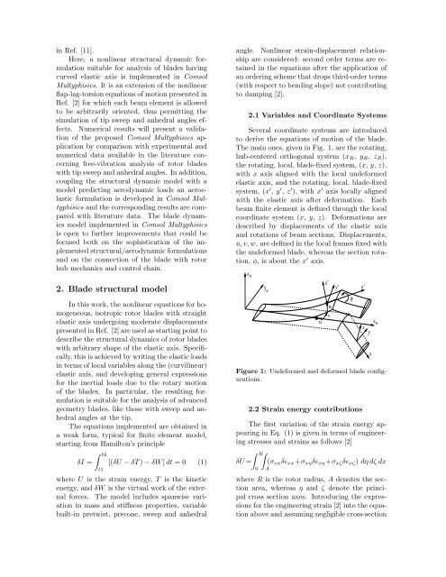
Several coordinate systems are introduced<br />
to derive the equations of motion of the blade.<br />
The main ones, given in Fig. 1, are the rotating,<br />
hub-centered orthogonal system (xR, yR, zR),<br />
the rotating, local, blade-fixed system, (x, y, z),<br />
with x axis aligned with the local undeformed<br />
elastic axis, and the rotating, local, blade-fixed<br />
system, (x ′ , y ′ , z ′ ), with x ′ axis locally aligned<br />
with the elastic axis after deformation. Each<br />
beam finite element is defined through the local<br />
coordinate system (x, y, z). Deformations are<br />
described by displacements of the elastic axis<br />
and rotations of beam sections. Displacements,<br />
u, v, w, are defined in the local frames fixed with<br />
the undeformed blade, whereas the section rotation,<br />
φ, is about the x ′ axis.<br />
z R<br />
y R<br />
u<br />
z’<br />
w<br />
v<br />
y’<br />
φ<br />
x’<br />
x<br />
z<br />
y<br />
Figure 1: Undeformed and deformed blade configurations.<br />
2.2 Strain energy contributions<br />
The first variation of the strain energy appearing<br />
in Eq. (1) is given in terms of engineering<br />
stresses and strains as follows [2]<br />
<br />
R<br />
δU =<br />
0<br />
(σxxδɛxx+σxηδɛxη +σxζδɛxζ) dη dζ dx<br />
A<br />
where R is the rotor radius, A denotes the section<br />
area, whereas η and ζ denote the principal<br />
cross section axes. Introducing the expressions<br />
for the engineering strain [2] into the equation<br />
above and assuming negligible cross-section<br />
x<br />
R