Datasheet #35995: DP5 Pump - Bijur Delimon
Datasheet #35995: DP5 Pump - Bijur Delimon
Datasheet #35995: DP5 Pump - Bijur Delimon

You also want an ePaper? Increase the reach of your titles
YUMPU automatically turns print PDFs into web optimized ePapers that Google loves.
<strong>DP5</strong> <strong>Pump</strong><br />
5:1, Air-operated, Heavy duty, Oil<br />
General<br />
The dP5 <strong>Pump</strong> is a compressed air-operated reciprocating piston medium pressure pump. These<br />
pumps are suitable for distribution of all types of light and heavy viscosity oil through pipe lines, hose<br />
reels and meters. High output allows simultaneous operation when used with multiple outlet systems.<br />
These pumps can be supplied as separate components systems with all elements necessary for its<br />
installation. <strong>Pump</strong>s may be mounted on drums, tanks or the wall, using the appropriate accessories.<br />
Operation<br />
This pump is self-priming. To prime it the first time, connect the air supply to the pump and slowly<br />
increase the air pressure from 0 to the desired pressure using a pressure regulator, while keeping<br />
the outlet valve opened. Once oil begins to flow through the oil gun/guns, the pump is primed.<br />
(Note: It is important that the foot valve of the pump does not come into contact with contaminated<br />
surfaces, such as a workshop floor, as it may become contaminated with dirt or foreign particles<br />
that can damage the seals.)<br />
Technical Data<br />
1<br />
Maximum Air Pressure 140 psi (10 bar)<br />
Minimum Air Pressure 40 psi (3 bar)<br />
Maximum Delivery 10 GPm (37 liter/min)<br />
Air Inlet Thread 3/8” nPT (F)<br />
Oil Outlet Thread 1” nPT (F)<br />
Air Piston Diameter ~4” (90mm)<br />
Air Piston Stroke 4” (100mm)<br />
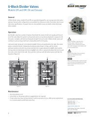
Installation<br />
These pumps can be mounted directly on a<br />
drums, tanks or on a wall bracket fitted with a<br />
2” bung. Loosen the star nut (33a) of the bung<br />
adapter to remove the inferior nut (33c) and<br />
screw this into the 2” bung opening of the drum<br />
or bracket. Place the star nut (33a) and the<br />
inside part (33b) on the suction tube. introduce<br />
the pump through the opening and fasten the<br />
assembly at the desired height by tightening the<br />
star nut (33a).<br />
33a<br />
33b<br />
33c<br />
Always keep fingers and hands away from<br />
moving parts. Do not dent or damage the<br />
riser tube.<br />
Ensure that the mounting surface and<br />
attachments are strong enough to<br />
support the lift and pump assembly<br />
during operation.<br />
BIJUR DELIMON INTERNATIONAL<br />
(919) 465 4448 LOCAL<br />
(800) 631 0168 TOLL-FREE<br />
(919) 465 0516 FAX<br />
www.bijuRdELimOn.COm<br />
2100 Gateway Centre blvd., Suite 109<br />
morrisville, nC 27560<br />
35995 • R1 09/10
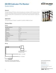
Typical Layout<br />
See drawing below for typical layout with all the recommended accessories for the pump to operate<br />
correctly. The compressed air supply must be between 40 and 140 psi (3 and 10 bar), 90 psi (6 bar)<br />
is the recommended pressure. An air shut-off valve must be installed to be able to close the<br />
compressed air line at the end of the day (if the air inlet is not closed and there is leakage in some<br />
point of the grease outlet circuit, the pump will start automatically, emptying the container).<br />
2<br />
A<br />
B<br />
1000mm<br />
C D E<br />
Item Description<br />
A Air shut-off valve<br />
b Filter regulator<br />
C Air hose<br />
d Quick coupler<br />
E Air nipple<br />
F 55:1 <strong>Pump</strong> (stub)<br />
G Pressure relief valve<br />
H Oil hose<br />
i Oil shut off valve<br />
j bung bushing adapter<br />
J<br />
K<br />
F<br />
G<br />
H<br />
TO THE OIL<br />
CONTAINER<br />
1500mm<br />
I<br />
BIJUR DELIMON INTERNATIONAL<br />
(919) 465 4448 LOCAL<br />
(800) 631 0168 TOLL-FREE<br />
(919) 465 0516 FAX<br />
www.bijuRdELimOn.COm<br />
2100 Gateway Centre blvd., Suite 109<br />
morrisville, nC 27560<br />
35995 • R1 09/10
Maintenance<br />
Separate the Air Motor from the <strong>Pump</strong><br />
1.<br />
2.<br />
3.<br />
3<br />
Secure the pump in a vice in the horizontal position, tightening the jaws on the provided pads<br />
along the air motor body (14).<br />
Gently strike the body base (31) a few times with a plastic hammer. To unscrew the suction tube<br />
(32) from the air motor body (14), use a 40mm wrench on the hex of the foot valve body (37).<br />
Pull clockwise first to break the seal, and then counter clockwise to loosen and remove the tube<br />
assembly, including the body base (31).<br />
Remove the upper roll pin (21) located in the upper part of the connecting rod (20) and unscrew<br />
the rod from the air piston (9). (See drawing on right.)<br />
Foot Valve<br />
1.<br />
2.<br />
Gently attach the suction tube assembly to the vice and unscrew the foot valve body (37) from<br />
the suction tube (32).<br />
Remove the roll pin (38) and clean the check ball (36), the check spring (35) and the ball seat.<br />
Replace any if damaged. Assemble pump following previous instructions, reversing each step.<br />
Upper Valve<br />
1.<br />
2.<br />
3.<br />
unscrew the valve seat (29) from the valve body (23) and remove the washer (28), the oil<br />
plunger seal (27), the washer (26), the check ball (25) and the check spring (24).<br />
Clean these parts carefully. if any damage is found, replace the affected parts.<br />
Assemble the pump following the previous instructions, reversing each step.<br />
Inverting Set and Air Motor<br />
1.<br />
2.<br />
3.<br />
4.<br />
5.<br />
6.<br />
Secure the air motor body (14) in a vice and unscrew the air motor cylinder (1) using a spanner<br />
wrench in the holes on the top of the air motor dolly.<br />
Check the upper spring (2) and the spring stop (3) inside the air motor cylinder (1). Replace<br />
if damaged.<br />
Remove the lower circlip (16) and muffler (15) and pull up the air motor assembly (4) until the<br />
hole in the pump piston (9) becomes visible in the opening where the muffler was removed.<br />
insert a steel rod (8mm) in the hole to lock the piston and prevent rotation.<br />
use a prepared 17mm wrench to remove the air motor assembly (4). (See drawing on right.)<br />
Remove the air piston (9) and disassemble the upper circlip (11), the washer (12) and the air<br />
piston seal (13). Check the piston for scratches and replace damaged parts.<br />
Assemble the pump following the previous instructions, reversing each step. use Loctite blue<br />
#242 (or equivalent) on the threads of the air-motor stem.<br />
Packing Set<br />
1. Follow the procedure for the air motor until the air piston (9) has been removed from the air<br />
motor body (14).<br />
2. Remove the circlip (19) and the packing set (18) from the air motor body (14). Replace<br />
if damaged.<br />
3. Assemble the pump following the previous instructions, reversing each step. (Note: The packing<br />
set is directional. It is not marked and must be installed correctly or it will leak. Look carefully at<br />
the inside diameter of the seal, you will see three components. The middle black ring that is split<br />
is a bearing. Above and below it are the brownish Turcite® seals, these are made with a step, and<br />
the step faces the oil. Confirm this by looking into the seal from both directions, from one side<br />
you will not see the steps, and from the other you will; this is the side that faces the oil.)<br />
Refer to page 5 for parts reference.<br />
Before starting any kind of maintenance<br />
or repair, disconnect the compressed air<br />
supply and open a downstream valve to<br />
relieve the grease pressure.<br />
Unscrew suction tube, remove rod<br />
Remove inverting set with 17mm wrench<br />
Packing set installation<br />
BIJUR DELIMON INTERNATIONAL<br />
(919) 465 4448 LOCAL<br />
(800) 631 0168 TOLL-FREE<br />
(919) 465 0516 FAX<br />
www.bijuRdELimOn.COm<br />
2100 Gateway Centre blvd., Suite 109<br />
morrisville, nC 27560<br />
35995 • R1 09/10
Troubleshooting<br />
4<br />
Symptom Possible Cause Remedy<br />
The pump is not working or there is no<br />
oil delivery.<br />
The pump begins to operate very fast<br />
and no oil is being delivered at the gun.<br />
The pump runs on continuously after<br />
the oil outlet is closed.<br />
Oil is leaking through the<br />
exhaust muffler.<br />
Air is leaking through the<br />
exhaust muffler.<br />
The oil delivery has diminished or the<br />
flow is uneven.<br />
The pump operates only one cycle<br />
and then stops.<br />
How to Order<br />
not enough air supply pressure. Slowly increase the air supply pressure.<br />
Some outlet line component is clogged<br />
or closed.<br />
The drum is empty or the oil level is<br />
beneath the suction tube inlet.<br />
There is an oil leak in some point of the<br />
outlet circuit.<br />
Contamination in the upper valve<br />
(23-28) or in the foot valve (31-35).<br />
Oil has by-passed to the air motor<br />
caused by worn or damaged packing<br />
set (17).<br />
The upper circlip (11) is worn<br />
or damaged.<br />
Clean or open the outlet circuit.<br />
Replace the drum or lower the suction<br />
tube until the inlet reaches below the<br />
oil level.<br />
Verify and tighten or repair.<br />
disassemble and clean.<br />
Replace damaged components.<br />
Replace the packing set.<br />
disassemble and clean.<br />
Replace damaged components.<br />
The air motor cylinder (1) is scored. Replace air motor dolly.<br />
The air piston rod (9) is scored. Replace the air piston rod.<br />
The air motor assembly (4) is worn<br />
or damaged.<br />
Contamination in the upper valve<br />
(23-28) or in the foot valve (31-35).<br />
Replace the air motor assembly.<br />
disassemble and clean.<br />
Replace damaged components.<br />
The upper spring (2) is damaged. Replace the upper spring.<br />
Name Drum Size Part #<br />
dP5 <strong>Pump</strong> Stub <strong>Pump</strong> F400<br />
16 gallon F406<br />
55 gallon F408<br />
when ordering, specify by name, description and part number, e.g. dP5 <strong>Pump</strong>, 16 Gallon drum,<br />
Part #F406.<br />
Refer to page 5 for parts reference.<br />
BIJUR DELIMON INTERNATIONAL<br />
(919) 465 4448 LOCAL<br />
(800) 631 0168 TOLL-FREE<br />
(919) 465 0516 FAX<br />
www.bijuRdELimOn.COm<br />
2100 Gateway Centre blvd., Suite 109<br />
morrisville, nC 27560<br />
35995 • R1 09/10
Service Parts<br />
5<br />
Item Description Part #<br />
1 Air motor cylinder F734101<br />
9 Air piston (5:1) F734619<br />
12 washer F734612<br />
14 Air motor body F734102<br />
15 muffler F835400<br />
16 Lower circlip F942730<br />
17 Packing set ---<br />
20 Connecting rod F735410<br />
31 body base adapter (5:1) F734605<br />
32 Suction tube (5:1) F734604<br />
33 bung adapter (5:1) F2031<br />
--- Air motor kit FAHK-1<br />
Upper spring (2) ---<br />
Spring stop (3) ---<br />
Air motor assembly (4) ---<br />
Lower inner spring (5) ---<br />
Lower outer spring (6) ---<br />
Air piston spacer (7) ---<br />
Lower spring carrier (8) ---<br />
Square cut seal (10) ---<br />
Body base O-ring (30) ---<br />
--- Packing set & seals kit FAHK-2<br />
Square cut seal (10) ---<br />
upper circlip (11) ---<br />
Air piston seal (13) ---<br />
Throat seal assembly (18) ---<br />
Lower circlip (19) ---<br />
Upper roll pin (21) ---<br />
Lower roll pin (22) ---<br />
Oil plunger seal (27) ---<br />
--- Lower end kit FAHK-3<br />
Upper roll pin (21) ---<br />
Lower roll pin (22) ---<br />
Oil plunger body (23) ---<br />
Check spring (24) ---<br />
Check ball (25) ---<br />
Upper washer (26) ---<br />
Oil plunger seal (27) ---<br />
Lower washer (28) ---<br />
Valve seat (29) ---<br />
1 9<br />
2<br />
3<br />
4<br />
5<br />
6<br />
7<br />
8<br />
16<br />
10<br />
11<br />
12<br />
13<br />
14<br />
15<br />
17<br />
18<br />
19<br />
20<br />
23<br />
24<br />
26<br />
28<br />
30<br />
32<br />
33<br />
34<br />
36<br />
37<br />
21<br />
22<br />
25<br />
27<br />
29<br />
31<br />
35<br />
38<br />
Service parts continue on page 6.<br />
BIJUR DELIMON INTERNATIONAL<br />
(919) 465 4448 LOCAL<br />
(800) 631 0168 TOLL-FREE<br />
(919) 465 0516 FAX<br />
www.bijuRdELimOn.COm<br />
2100 Gateway Centre blvd., Suite 109<br />
morrisville, nC 27560<br />
35995 • R1 09/10
Service Parts (Cont.)<br />
6<br />
Item Description Part #<br />
--- Foot valve kit FFV-51<br />
Foot valve O-ring (34) ---<br />
Foot valve check spring (35) ---<br />
Check ball (36) ---<br />
Foot valve body (37) ---<br />
Foot valve roll pin (38) ---<br />
Dimensional Schematics<br />
AIR<br />
IN<br />
3/8”<br />
Part # A B C D<br />
F400 720mm<br />
(28.3”)<br />
F408 1355mm<br />
(53.3”)<br />
OIL<br />
OUT<br />
1”<br />
A<br />
440mm<br />
(17.3”)<br />
440mm<br />
(17.3”)<br />
B<br />
42mm<br />
(1.65”)<br />
42mm<br />
(1.65”)<br />
C<br />
280mm<br />
(11”)<br />
915mm<br />
(36”)<br />
D<br />
See reference image on page 5.<br />
Measurements shown in millimeters.<br />
BIJUR DELIMON INTERNATIONAL<br />
(919) 465 4448 LOCAL<br />
(800) 631 0168 TOLL-FREE<br />
(919) 465 0516 FAX<br />
www.bijuRdELimOn.COm<br />
2100 Gateway Centre blvd., Suite 109<br />
morrisville, nC 27560<br />
35995 • R1 09/10