UWW-170 (UNITOR) - Lincoln Electric
UWW-170 (UNITOR) - Lincoln Electric
UWW-170 (UNITOR) - Lincoln Electric

You also want an ePaper? Increase the reach of your titles
YUMPU automatically turns print PDFs into web optimized ePapers that Google loves.
Index of Sub Assemblies Index of Sub Assemblies Index of Sub Assemblies Index of Sub Assemblies<br />
Illustration of Sub Assemblies Illustration of Sub Assemblies Illustration of Sub Assemblies Illustration of Sub Assemblies<br />
P-298<br />
RETURN TO MAIN INDEX<br />
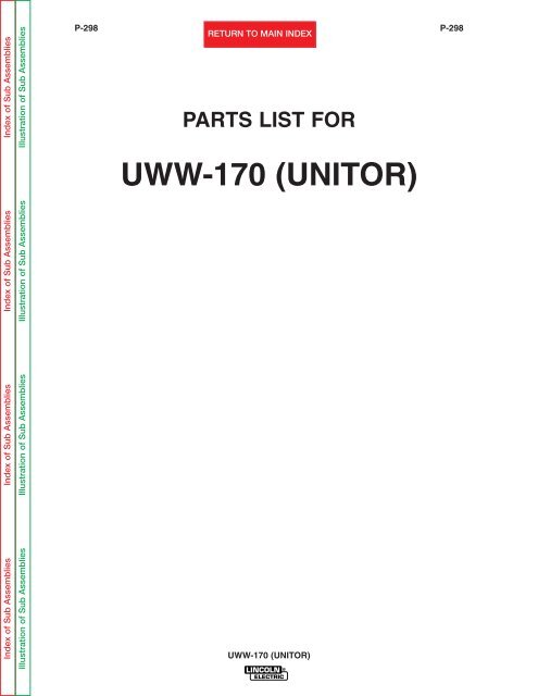
PARTS LIST FOR<br />
<strong>UWW</strong>-<strong>170</strong> (<strong>UNITOR</strong>)<br />
<strong>UWW</strong>-<strong>170</strong> (<strong>UNITOR</strong>)<br />
P-298
Index of Sub Assemblies Index of Sub Assemblies Index of Sub Assemblies Index of Sub Assemblies<br />
P-298-A<br />
MAIN ASSEMBLY<br />
1<br />
<strong>UWW</strong>-<strong>170</strong> (<strong>UNITOR</strong>)<br />
5<br />
6<br />
<strong>UWW</strong>-<strong>170</strong> (<strong>UNITOR</strong>)<br />
4<br />
2<br />
3<br />
P-298-A<br />
1<br />
02-23-2007
Illustration of Sub Assemblies Illustration of Sub Assemblies Illustration of Sub Assemblies Illustration of Sub Assemblies<br />
P-298-A.1<br />
<strong>UWW</strong>-<strong>170</strong> (<strong>UNITOR</strong>)<br />
For Codes: 10490, 10634 & 10694<br />
Do Not use this Parts List for a machine if its code number is not listed. Contact the Service Department for any<br />
code numbers not listed.<br />
Use the Main Assembly drawing on the left hand page and the table below to determine which sub assembly<br />
page and column the desired part is located on for your particular code machine.<br />
Sub Assembly<br />
Item No.<br />
SUB ASSEMBLY<br />
PAGE NAME<br />
PAGE NO.<br />
CODE NO.<br />
Optional Equipment<br />
Miscellaneous Items<br />
1<br />
Case Side & Door Assembly<br />
P298-B.1 P298-B.2 P-298-C<br />
RETURN TO MAIN INDEX<br />
Center Panel Assembly<br />
<strong>UWW</strong>-<strong>170</strong> (<strong>UNITOR</strong>)<br />
Case Back and Bottom<br />
Assembly<br />
Rectifier & Fan Motor<br />
Assembly<br />
P-298-A.1<br />
10490 1 1 1 1 5 1 1 1 1<br />
10634 1 1 1 1 5 1 1 1 1<br />
10694 1 1 1 1 5 1 1 1 1<br />
2<br />
P-298-D<br />
3<br />
Wire Drive Assembly<br />
P-189-D<br />
4<br />
P-298-E<br />
5<br />
Case Front Assembly<br />
P-298-F<br />
6<br />
P-298-G<br />
Gun and Cable Assembly<br />
P103-Y<br />
02-23-2007
Index of Sub Assemblies Index of Sub Assemblies Index of Sub Assemblies Index of Sub Assemblies<br />
P-298-B.1<br />
OPTIONAL EQUIPMENT LISTING<br />
Miscellaneous Options Available for your machine are listed below:<br />
# Indicates a change this printing.<br />
Use only the parts marked “x” in the column under the<br />
heading number called for in the model index page.<br />
DESCRIPTION PART NO. 1 2 3 4 5 6 7 8 9<br />
Utility Cart Order K520 X<br />
Drive Roll (.035/.045 Knurled) Order KP665-045C X<br />
Spot/Stich Timer Kit Order K695-1 X<br />
035 Innershield Welding Kit Order K464 X<br />
.045 Innershield Welding Kit Order K491 X<br />
<strong>UWW</strong>-<strong>170</strong> (<strong>UNITOR</strong>)<br />
P-298-B.1<br />
02-23-2007
Index of Sub Assemblies Index of Sub Assemblies Index of Sub Assemblies Index of Sub Assemblies<br />
P-298-B.2<br />
# Indicates a change this printing.<br />
MISCELLANEOUS ITEMS<br />
(THESE ITEMS ARE NOT ILLUSTRATED)<br />
Socket Key T11563-4 1 X<br />
Work Cable S11609-19 1 X<br />
Light Duty Clamp M12033 1 X<br />
Gun & Cable L10744 1 X<br />
Gas Line Assembly S19303-2 1 X<br />
Multi-Purpose Welding Pliers S24044 1 X<br />
.8mm (.030) Contact Tip KP2011-2B1 2 X<br />
1.2mm (.045) Contact Tip KP2011-7B1 2 X<br />
Gasless Nozzle KP2011-8 1 X<br />
<strong>UWW</strong>-<strong>170</strong> (<strong>UNITOR</strong>)<br />
P-298-B.2<br />
Use only the parts marked “x” in the column under the<br />
heading number called for in the model index page.<br />
ITEM DESCRIPTION PART NO. QTY. 1 2 3 4 5 6 7 8 9<br />
02-23-2007
Index of Sub Assemblies Index of Sub Assemblies Index of Sub Assemblies Index of Sub Assemblies<br />
Part Numbers Part Numbers Part Numbers Part Numbers<br />
P-298-C<br />
Case Side & Door Assembly<br />
1A<br />
1<br />
2<br />
5<br />
6<br />
<strong>UWW</strong>-<strong>170</strong> (<strong>UNITOR</strong>)<br />
3<br />
P-298-C<br />
4<br />
02-23-2007
Index of Sub Assemblies Index of Sub Assemblies Index of Sub Assemblies Index of Sub Assemblies<br />
Sub Assembly Illustration Sub Assembly Illustration Sub Assembly Illustration Sub Assembly Illustration<br />
P-298-C.1<br />
# Indicates a change this printing.<br />
1 Case Side L7554-6 1 X<br />
1A Self Tapping Screw S8025-65 8 X<br />
2 Handle M15446 1 X<br />
2A Thread Forming Screw (Not Shown) S9225-53 2 X<br />
3 Wiring Diagram M18931 1 X<br />
4 Case Door L7555-3 1 X<br />
5 Procedure sheet L10743 1 X<br />
6 Door Hinge M15451 2 X<br />
7 Decal Logo (Not Shown) S24045 2 X<br />
7 Decal Warranty (Not Shown) S22127-1 1 X<br />
<strong>UWW</strong>-<strong>170</strong> (<strong>UNITOR</strong>)<br />
P-298-C.1<br />
Use only the parts marked “x” in the column under the<br />
heading number called for in the model index page.<br />
ITEM DESCRIPTION PART NO. QTY. 1 2 3 4 5 6 7 8 9<br />
02-23-2007
Index of Sub Assemblies Index of Sub Assemblies Index of Sub Assemblies Index of Sub Assemblies<br />
Part Numbers Part Numbers Part Numbers Part Numbers<br />
P-298-D<br />
Center Panel Assembly<br />
20<br />
7B<br />
21<br />
1<br />
19<br />
2<br />
18<br />
17<br />
16<br />
<strong>UWW</strong>-<strong>170</strong> (<strong>UNITOR</strong>)<br />
15<br />
14<br />
13<br />
12<br />
4<br />
11<br />
5<br />
6<br />
4A<br />
7A 7<br />
10<br />
8<br />
3<br />
P-298-D<br />
9<br />
02-23-2007
Index of Sub Assemblies Index of Sub Assemblies Index of Sub Assemblies Index of Sub Assemblies<br />
Sub Assembly Illustration Sub Assembly Illustration Sub Assembly Illustration Sub Assembly Illustration<br />
P-298-D.1<br />
# Indicates a change this printing.<br />
1 Lead Harness (J1) G1949-4 1 X<br />
2 Control P.C. Board L8926-[ ] 1 X<br />
3 P.C. Board Support S19300-2 7 X<br />
4 Gas Solenoid Assembly S18431-5 1 X<br />
4A Sems Screw (Not Shown) T10082-27 2 X<br />
5 Self Tapping Screw S8025-92 2 X<br />
6 Center Panel L7826-9 1 X<br />
7 Thread Forming Screw S9225-36 1 X<br />
7A Lock Washer T9695-1 1 X<br />
7B #10-24 HN CF000010 1 X<br />
8 Receptacle T14530-1 2 X<br />
9 Thumb Screw (Below Code 10650) S18438 1 X<br />
9 Wing Nut (Above Code 10650) T9968-5 1 X<br />
10 Wire Reel Spindle M15445 1 X<br />
11 Set Screw (Below Code 10650) S11604-19 1 X<br />
12 Spindle Shaft (Below Code 10650) S18441 1 X<br />
12 Spindle Shaft (Above Code 10650) S24227 1 X<br />
13 Wear Plate S18423 1 X<br />
14 Bow Washer T10781-10 1 X<br />
15 Plain Washer S9262-120 1 X<br />
16 Lock Washer E106A-16 1 X<br />
17 3/8-16 HN CF000067 1 X<br />
18 Cable Clamp T12563-6 1 X<br />
19 Self Tapping Screw S8025-65 2 X<br />
20 Gas Line T10642-143 1 X<br />
21 Circuit Breaker T12287-21 1 X<br />
22A Blank Panel Asbly (Not Shown) S22199 1 X<br />
22B Self Tapping Screw (Not Shown) S8025-76 1 X<br />
22C Plug & Lead Asbly (Not Shown) (Spot Stich Timer) S18250-433 1 X<br />
22D Self Tapping Screw (Not Shown) (J3) S8025-65 1 X<br />
22E Plug & Lead Asbly (Not Shown) S18250-434 1 X<br />
22F Lead Harness (J2) (Not Shown) S18250-94 1 X<br />
23A Transformer Support Bracket S24612 1 X<br />
23B Self Tapping Screw S8025-92 1 X<br />
<strong>UWW</strong>-<strong>170</strong> (<strong>UNITOR</strong>)<br />
P-298-D.1<br />
Use only the parts marked “x” in the column under the<br />
heading number called for in the model index page.<br />
ITEM DESCRIPTION PART NO. QTY. 1 2 3 4 5 6 7 8 9<br />
Note: When ordering new printed circuit boards indicate the dash number [ ] of the “Old” board<br />
that is to be replaced. This will aid <strong>Lincoln</strong> in supplying the correct and latest board along<br />
with any necessary jumpers or adapters. The dash number brackets [ ] have purposely<br />
been left blank so as to eliminate errors, confusion and updates.<br />
02-23-2007
Index of Sub Assemblies Index of Sub Assemblies Index of Sub Assemblies Index of Sub Assemblies<br />
Part Numbers Part Numbers Part Numbers Part Numbers<br />
P-298-E<br />
Case Back & Bottom Assembly<br />
6<br />
1 1A<br />
5<br />
<strong>UWW</strong>-<strong>170</strong> (<strong>UNITOR</strong>)<br />
2 3<br />
4<br />
P-298-E<br />
02-23-2007
Index of Sub Assemblies Index of Sub Assemblies Index of Sub Assemblies Index of Sub Assemblies<br />
Sub Assembly Illustration Sub Assembly Illustration Sub Assembly Illustration Sub Assembly Illustration<br />
P-298-E.1<br />
# Indicates a change this printing.<br />
1 Transformer, Choke & Switch Asbly Not Sold 1 X<br />
1A Transformer & Choke Asbly L8004-1 1 X<br />
2 Case Back and Bottom G3337 1 X<br />
3 Input Cordset S19836-2 1 X<br />
3A Lead Grommet (Not Shown) T9274-10 1 X<br />
4 Fastener Button T14659-1 2 X<br />
5 Self Tapping Screw S8025-70 4 X<br />
6 Capacitor S13490-122 1 X<br />
<strong>UWW</strong>-<strong>170</strong> (<strong>UNITOR</strong>)<br />
P-298-E.1<br />
Use only the parts marked “x” in the column under the<br />
heading number called for in the model index page.<br />
ITEM DESCRIPTION PART NO. QTY. 1 2 3 4 5 6 7 8 9<br />
02-23-2007
Index of Sub Assemblies Index of Sub Assemblies Index of Sub Assemblies Index of Sub Assemblies<br />
Part Numbers Part Numbers Part Numbers Part Numbers<br />
P-298-F<br />
Case Front Assembly<br />
14<br />
16A<br />
13<br />
16<br />
1<br />
2<br />
2B<br />
16B<br />
<strong>UWW</strong>-<strong>170</strong> (<strong>UNITOR</strong>)<br />
2A<br />
12 11 10 9<br />
<strong>UWW</strong>-<strong>170</strong> (<strong>UNITOR</strong>)<br />
8 7 6 5<br />
16<br />
4<br />
3<br />
P-298-F<br />
02-23-2007
Index of Sub Assemblies Index of Sub Assemblies Index of Sub Assemblies Index of Sub Assemblies<br />
Sub Assembly Illustration Sub Assembly Illustration Sub Assembly Illustration Sub Assembly Illustration<br />
P-298-F.1<br />
# Indicates a change this printing.<br />
Use only the parts marked “x” in the column under the<br />
heading number called for in the model index page.<br />
1 Line Switch S18815 1 X<br />
1A #6-32 X .50 PPNHS (Not Shown) CF000338 2 X<br />
1B Line Switch Insulation (Not Shown) S20001-2 1 X<br />
2 Case Front A464 1 X<br />
2A Self Tapping Screw S8025-65 2 X<br />
2B Self Tapping Screw S8025-70 1 X<br />
3 Potentiometer T10812-37 or -109 1 X<br />
4 Wing Nut T9968-1 2 X<br />
5 1/4-20 Br HN CF000300 2 X<br />
6 3/8-16 HJN CF000121 2 X<br />
7 Lock Washer T9695-15 2 X<br />
8 Plain Washer S9262-120 2 X<br />
9 Polarity Stud S18432 2 X<br />
10 Plain Washer S9262-98 2 X<br />
11 Lock Washer E106A-2 2 X<br />
12 1/4-20 x .50 HHCS CF000012 2 X<br />
13 Fastener Button T14659-1 4 X<br />
14 Knob (Wire Speed) S18425-1 1 X<br />
15 Name Plate M18937 1 X<br />
16 Voltage Control Switch M15750-1 1 X<br />
16A Knob (Voltage Switch) M15796 1 X<br />
<strong>UWW</strong>-<strong>170</strong> (<strong>UNITOR</strong>)<br />
P-298-F.1<br />
ITEM DESCRIPTION PART NO. QTY. 1 2 3 4 5 6 7 8 9<br />
02-23-2007
Index of Sub Assemblies Index of Sub Assemblies Index of Sub Assemblies Index of Sub Assemblies<br />
Part Numbers Part Numbers Part Numbers Part Numbers<br />
P-298-G<br />
Rectifier & Fan Motor Assembly<br />
Early Design<br />
1A<br />
1B<br />
3<br />
1C<br />
2<br />
1F<br />
1E<br />
3A<br />
5<br />
3B<br />
<strong>UWW</strong>-<strong>170</strong> (<strong>UNITOR</strong>)<br />
6<br />
3<br />
7<br />
2<br />
3A<br />
P-298-G<br />
3B<br />
Present Design<br />
02-23-2007
Index of Sub Assemblies Index of Sub Assemblies Index of Sub Assemblies Index of Sub Assemblies<br />
Sub Assembly Illustration Sub Assembly Illustration Sub Assembly Illustration Sub Assembly Illustration<br />
P-298-G.1<br />
# Indicates a change this printing.<br />
Use only the parts marked “x” in the column under the<br />
heading number called for in the model index page.<br />
1 Rectifier Assembly, Includes: (Early Design Only) M15966-1 1 X<br />
1A Heat Sink NSS 2 X<br />
1B Negative Rectifier Diode M9661-39R 4 X<br />
1C Positive Rectifier Diode M9661-39 4 X<br />
1D Thermostat (Not Shown) T13359-12 1 X<br />
1E 1/4-28 HJN CF000060 8 X<br />
1F Spring Washer T12735-4 8 X<br />
2 Fan & Heat Sink Bracket G1839 1 X<br />
3 Fan Motor M15787-2 1 X<br />
3A Blade M15432 1 X<br />
3B Sems Screw T10082-27 2 X<br />
5 Rectifier Assembly (Present Design Only) L12108 1 X<br />
6 Thermostat T13359-12 1 X<br />
7 Self Tapping Screw S8025-96 2 X<br />
<strong>UWW</strong>-<strong>170</strong> (<strong>UNITOR</strong>)<br />
P-298-G.1<br />
ITEM DESCRIPTION PART NO. QTY. 1 2 3 4 5 6 7 8 9<br />
NSS- Not Sold Separately<br />
02-23-2007
Index of Sub Assemblies Index of Sub Assemblies Index of Sub Assemblies Index of Sub Assemblies<br />
NOTES<br />
<strong>UWW</strong>-<strong>170</strong> (<strong>UNITOR</strong>)