Operating Manual - Winkhaus
Operating Manual - Winkhaus
Operating Manual - Winkhaus

You also want an ePaper? Increase the reach of your titles
YUMPU automatically turns print PDFs into web optimized ePapers that Google loves.
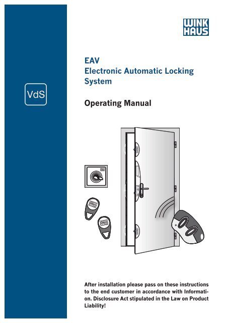
EAV<br />
Electronic Automatic Locking<br />
System<br />
<strong>Operating</strong> <strong>Manual</strong><br />
After installation please pass on these instructions<br />
to the end customer in accordance with Information.<br />
Disclosure Act stipulated in the Law on Product<br />
Liability!
1<br />
2<br />
3<br />
4<br />
5<br />
6<br />
7<br />
8<br />
<strong>Operating</strong> <strong>Manual</strong> EAV 2<br />
Aug. <strong>Winkhaus</strong> GmbH & Co. KG · Berkeser Str. 6 · D-98617 Meiningen · www.winkhaus.de<br />
Subject to technical changes<br />
Print-no. 250 020 1<br />
08/2009<br />
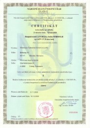
This security door locking system complies with the requirements and directives established<br />
and stipulated by the Council on the Harmonization of Legal Regulations of<br />
Member States regarding Electromagnetic Compatibility (89/336/EEC).<br />
The manufacturer shall hereby certify the conformity of this product and document<br />
such by the CE marking (see Appendix).<br />
Aug. <strong>Winkhaus</strong> GmbH & Co. KG<br />
Berkeser Straße 6<br />
D-98617 Meiningen<br />
Germany<br />
T + 49 (0) 3693 950-0<br />
F + 49 (0) 3693 950-134<br />
www.winkhaus.de<br />
The following information and graphic images provided correspond to the current<br />
status of the development and manufacture of this product.<br />
For the purpose of customer satisfaction and operational reliability of the electronic automatic<br />
locking system, we reserve the right to make changes to this product without<br />
notice.<br />
All information and specifications given in this operating manual have been compiled<br />
and reviewed with the utmost care.<br />
Due to the nature of advances in technology, or amendments to legal regulations and<br />
other compulsory changes we do not guarantee the accuracy and completeness of the<br />
contents’ statements. We always appreciate suggestions or comments.<br />
The electronic automatic locking system can be easily installed, if these operating instructions<br />
and the door specifications indicated have been adhered to.<br />
© Aug. <strong>Winkhaus</strong> GmbH & Co. KG. All rights reserved. Last revised: 08/2009
<strong>Operating</strong> <strong>Manual</strong> EAV 3<br />
Table of contents<br />
Print-no. 250 020 1<br />
08/2009<br />
1 Important information page 5<br />
1.1 General information page 5<br />
1.2 Intended use page 5<br />
1.3 Use contrary to the intended purpose page 6<br />
1.4 Explanation of symbols page 7<br />
1.5 Important safety information page 7<br />
1.6 Abbreviations/Explanations page 8<br />
2 Product description page 9<br />
3 Installation page 17<br />
3.1 Routing details page 17<br />
3.2 Cable transition KÜ-T-STV (plug-in) page 19<br />
3.3 Installations page 21<br />
3.3.1 General connection diagram page 22<br />
3.4 Access control system transponder set page 23<br />
3.5 Access control system wireless remote control page 25<br />
3.5.1 Wireless remote control set page 25<br />
3.5.2 Wireless receiver (separate) page 27<br />
3.6 Non-<strong>Winkhaus</strong> access control system page 29<br />
3.6.1 Non-<strong>Winkhaus</strong> access control system general page 29<br />
3.6.2 Non-<strong>Winkhaus</strong> access control system finger<br />
scanner ekey home integra page 29<br />
3.6.2.1 Control of additional applications (only integra 2) page 31<br />
3.6.2.2 Control of automatic door opener (integra 1 and 2) page 31<br />
Aug. <strong>Winkhaus</strong> GmbH & Co. KG · Berkeser Str. 6 · D-98617 Meiningen · www.winkhaus.de<br />
Subject to technical changes<br />
General<br />
information<br />
1<br />
Important<br />
information<br />
Installation<br />
2<br />
Product<br />
description<br />
3<br />
4<br />
Operation<br />
Programming<br />
5<br />
Maintenance<br />
and care<br />
6<br />
Errors<br />
Troubleshooting<br />
7<br />
Technical<br />
specifications<br />
8<br />
Accessories
1<br />
2<br />
3<br />
4<br />
5<br />
6<br />
7<br />
8<br />
<strong>Operating</strong> <strong>Manual</strong> EAV 4<br />
Table of contents<br />
Aug. <strong>Winkhaus</strong> GmbH & Co. KG · Berkeser Str. 6 · D-98617 Meiningen · www.winkhaus.de<br />
Subject to technical changes<br />
Print-no. 250 020 1<br />
08/2009<br />
4 Operation/Programming page 32<br />
4.1 Electronic automatic locking system page 32<br />
4.1.1 Locking and unlocking page 32<br />
4.2 Electronic automatic door locking system with transponder page 32<br />
4.2.1 Operation page 32<br />
4.2.2 Programming page 33<br />
4.3 Electronic automatic locking system with<br />
wireless remote control page 35<br />
4.3.1 Operation page 35<br />
4.3.2 Programming page 35<br />
4.4 Wireless receiver for additional applications page 39<br />
5 Maintenance and care page 40<br />
6 Errors/Causes/Troubleshooting page 41<br />
7 Technical specifications page 43<br />
7.1 Power supply page 43<br />
7.2 Antenna/Reader unit page 43<br />
7.3 Wireless remote control page 43<br />
7.4 Cable transition KÜ-T ... page 45<br />
8 Accessories page 46
<strong>Operating</strong> <strong>Manual</strong> EAV 5<br />
1 Important information<br />
1.1 General information<br />
Dear Customer,<br />
Aug. <strong>Winkhaus</strong> GmbH & Co. KG · Berkeser Str. 6 · D-98617 Meiningen · www.winkhaus.de<br />
Subject to technical changes<br />
Print-no. 250 020 1<br />
08/2009<br />
We would like to thank you for your confidence you have put in us by purchasing our<br />
high-quality product.<br />
Please read this operating manual carefully to become acquainted with the installation<br />
and use of this security door locking system and to avoid malfunctions and safety<br />
hazards.<br />
Acceptance class A<br />
„Acceptance-No.: M105301“<br />
1.2 Intended use<br />
The electronic automatic locking system and the <strong>Winkhaus</strong> components recommended<br />
are suitable for the following areas of application:<br />
• relative air humidity of max. 95%<br />
• ambient air temperature of between - 20°C and + 60°C.<br />
The complete door fittings are designed to be used in conjunction with genuine <strong>Winkhaus</strong><br />
parts. Other parts which are not recommended by <strong>Winkhaus</strong> can adversely affect<br />
the default properties of this locking system. It is assumed that the lock will be used<br />
as intended.<br />
The proper functions of the access control systems and the accessories included in the<br />
scope of delivery of the <strong>Winkhaus</strong> company have been tested. If you use components<br />
made by other companies and if you have any doubts about the suitability of these<br />
components, you will have to contact the respective manufacturer to ensure their fitness<br />
for use.<br />
To ensure the intended use:<br />
• the information and instructions required for this purpose have to be passed on to<br />
the respective persons;<br />
General<br />
information<br />
1<br />
Important<br />
information<br />
Installation<br />
2<br />
Product<br />
description<br />
3<br />
4<br />
Operation<br />
Programming<br />
5<br />
Maintenance<br />
and care<br />
6<br />
Errors<br />
Troubleshooting<br />
7<br />
Technical<br />
specifications<br />
8<br />
Accessories
1<br />
2<br />
3<br />
4<br />
5<br />
6<br />
7<br />
8<br />
<strong>Operating</strong> <strong>Manual</strong> EAV 6<br />
Aug. <strong>Winkhaus</strong> GmbH & Co. KG · Berkeser Str. 6 · D-98617 Meiningen · www.winkhaus.de<br />
Subject to technical changes<br />
Print-no. 250 020 1<br />
08/2009<br />
• only trained professionals should install the door fittings, locking units and accessories<br />
according to the installation instructions. DIN standards, which may also<br />
apply are to be followed, also.<br />
The stipulations for use as intended have been met, once the <strong>Winkhaus</strong> fittings are:<br />
• installed according to their defined function and the installation specifications,<br />
• not used in any other way than described,<br />
• maintained and cared for at regular intervals as instructed,<br />
• not used if signs of wear are detected,<br />
• repaired by trained professionals in the event of malfunctions.<br />
The supplier/manufacturer does not accept any liability for personal injury or material<br />
damage caused by incorrect operation or improper use.<br />
1.3 Use contrary to the intended purpose<br />
The locking systems are not designed to absorb or compensate for any movement<br />
changes or in the closing mechanism of the door caused by changes in temperature or<br />
in the structure of the building.<br />
Doors which are used in damp rooms and in environments with aggressive corrosion<br />
related air conditions require special door furniture.<br />
Incorrect use of the locking systems is evident if :<br />
• the instructions on the intended use are not being followed;<br />
• the problem-free operation is hindered due to the installation of external items that<br />
are not suitable or block the external outside function, the locking system or within<br />
the center keep;<br />
• the locking system or the center keep is manipulated in such a way that its design,<br />
mode of operation or function is changed;<br />
• the door is drilled through in the area of the lock housings or of the lock rod once<br />
the lock has been installed;<br />
• the additional opening and closing equipment or the thrown dead bolt are improperly<br />
used in order to keep the door open;<br />
• force is used to drive the handle pin through the lock spindle;<br />
• the locking components are wrongly installed or are tampered with, e.g. by painting<br />
over movable parts such as the lock dead bolt or latch;
<strong>Operating</strong> <strong>Manual</strong> EAV 7<br />
Aug. <strong>Winkhaus</strong> GmbH & Co. KG · Berkeser Str. 6 · D-98617 Meiningen · www.winkhaus.de<br />
Subject to technical changes<br />
Print-no. 250 020 1<br />
08/2009<br />
• the locking system is subject to loads which exceed normal manual force and are<br />
transmitted via the cylinder key;<br />
• the handle is not loaded in the normal sense of rotation or a a force above 150 N<br />
is applied onto the handle in the direction of actuation;<br />
• the gap between the door frame and sash is increased or decreased, which would<br />
for instance result from readjusting the hinges or if the door drops;<br />
• auxiliary lifting tools or objects are used to open or close the lock;<br />
• the handle and the key are actuated simultaneously;<br />
• the lock is locked/unlocked by using improper tools or equipment;<br />
• Incorrect input values are applied in contravention of the Technical specifications.<br />
1.4 Explanation of symbols<br />
Symbols and flags are used to identify important information in this operating manual.<br />
Flags such as DANGER or CAUTION indicate the degree of hazard. Symbols serve to<br />
visually emphasize the message.<br />
It is imperative that you follow the measures listed to avoid hazard to safety!<br />
DANGER!<br />
Danger to life or danger of serious injuries.<br />
CAUTION!<br />
Danger of material damage.<br />
+ NOTICE!<br />
Useful information and tips.<br />
ECO-WATCH!<br />
Notices on complying with regulations on environmental protection.<br />
1.5 Important safety information<br />
Safety information described in this section is to be diligently adhered to regarding<br />
the installation and use of this security lock. You must heed to the safety information<br />
provided without exceptions!<br />
• Read the operating manual and keep it easily accessible for future reference. After<br />
installing the door pass it on to the end customer.<br />
General<br />
information<br />
1<br />
Important<br />
information<br />
Installation<br />
2<br />
Product<br />
description<br />
3<br />
4<br />
Operation<br />
Programming<br />
5<br />
Maintenance<br />
and care<br />
6<br />
Errors<br />
Troubleshooting<br />
7<br />
Technical<br />
specifications<br />
8<br />
Accessories
1<br />
2<br />
3<br />
4<br />
5<br />
6<br />
7<br />
8<br />
<strong>Operating</strong> <strong>Manual</strong> EAV 8<br />
Aug. <strong>Winkhaus</strong> GmbH & Co. KG · Berkeser Str. 6 · D-98617 Meiningen · www.winkhaus.de<br />
Subject to technical changes<br />
Print-no. 250 020 1<br />
08/2009<br />
• The manufacturer shall not be held liable for damage caused by use contrary to<br />
the intended purpose of the product.<br />
• For security reasons, the lock has been designed to be used in conjunction with genuine<br />
<strong>Winkhaus</strong> parts. Using other parts may adversely affect the given properties<br />
of the security lock.<br />
• It must be ensured that the door can be closed without any difficulties with the key.<br />
• Installation/Repair of electrical equipment requires expertise, thus such work<br />
should only be carried out by a qualified electrician.<br />
• Arbitrary modifications, changes or makeshift repairs are not permitted due to<br />
concerns for safety. You must only use genuine <strong>Winkhaus</strong> parts for replacements.<br />
• The manufacturer shall only be held liable for security related properties of the<br />
locking system as stipulated within the bounds of statutory regulations, if the manufacturer<br />
himself or another instructed, authorized agent has carried out the<br />
maintenance and service work or made the changes.<br />
• <strong>Winkhaus</strong> shall not be liable for any type of damage caused by inadequate repair<br />
or changes made.<br />
1.6 Abbreviations/Explanations<br />
The following terms and abbreviations are used in this manual:<br />
STV Security lock<br />
AV2 Automatic locking system<br />
EAV Electronic automatic locking<br />
system<br />
Handle Door handle<br />
Grt. Set<br />
SB FRA Center keeps – latch/dead<br />
bolt/adjustment plate<br />
M2 with 2 hooks<br />
RS DIN-right-handed<br />
LS DIN-left-handed<br />
mc Surface matt chrome-plated<br />
est stainless steel<br />
gr grey powder coated<br />
Reader Reader unit/control unit of<br />
the transponder set<br />
AC Alternating current<br />
DC Direct current<br />
NO Make contact<br />
NC Break contact<br />
NO-NC Changer contact<br />
ANT/GND Auxiliary antenna/Ground<br />
UP-socket Flush-type box<br />
LED Light emitting diode<br />
PE Ground wire<br />
N Neutral wire<br />
L Phase
<strong>Operating</strong> <strong>Manual</strong> EAV 9<br />
2 Product description<br />
Print-no. 250 020 1<br />
08/2009<br />
The electronic automatic locking system is a state-of-the-art locking unit for securing<br />
and locking entry doors in a contact-free manner. The hooks can be retracted electrically<br />
so as to open the door.<br />
In the<br />
external zone<br />
around the<br />
entry door<br />
Figure 2-1: Electronic automatic locking system with accessories<br />
+ + - -<br />
N L<br />
+ V - V<br />
Netzteil/Powersupply<br />
INPUT: 100 - 240 V AC; 50/60 Hz<br />
OUTPUT: 12 V DC; 2 A<br />
Aug. <strong>Winkhaus</strong> GmbH & Co. KG · Berkeser Str. 6 · D-98617 Meiningen · www.winkhaus.de<br />
Subject to technical changes<br />
General<br />
information<br />
1<br />
Important<br />
information<br />
Installation<br />
2<br />
Product<br />
description<br />
3<br />
4<br />
Operation<br />
Programming<br />
5<br />
Maintenance<br />
and care<br />
6<br />
Errors<br />
Troubleshooting<br />
7<br />
Technical<br />
specifications<br />
8<br />
Accessories
1<br />
2<br />
3<br />
4<br />
5<br />
6<br />
7<br />
8<br />
<strong>Operating</strong> <strong>Manual</strong> EAV 10<br />
Aug. <strong>Winkhaus</strong> GmbH & Co. KG · Berkeser Str. 6 · D-98617 Meiningen · www.winkhaus.de<br />
Subject to technical changes<br />
Print-no. 250 020 1<br />
* remaining components recommended for use, or should be used alternatively<br />
08/2009<br />
No. Name Included MUST! Available Supplied<br />
in standard Manda- as an by custo-<br />
delivery of tory * accessory mer/not<br />
the security<br />
or as an included in<br />
lock<br />
option standard<br />
delivery<br />
1 Automatic locking AV2<br />
(AV2-F/U ...)<br />
X X<br />
2 Motor housing X X<br />
3<br />
Extension keep set/single<br />
keep<br />
X X<br />
4 Center keep FRA ... X X<br />
5 Cable transition (KÜ-T-STV) X X<br />
5.1 Cable at the sash side 2 m<br />
[2.187 yd] or 3.5 m<br />
[3.829 yd] long, plug for<br />
motor housing included<br />
5.2 Cable for the frame side<br />
4 m [4.374 yd] long<br />
6 Power supply 12V DC/2A X<br />
7<br />
Access control system<br />
(shown: antenna of the transponder<br />
set)<br />
+ NOTICE! Only install<br />
the antenna of the transponder<br />
set in the external zone<br />
around the entry door!<br />
8 „Open” button X<br />
9 Flush-type box X<br />
10 Handle X<br />
X
<strong>Operating</strong> <strong>Manual</strong> EAV 11<br />
1 Automatic locking system AV2<br />
Optional electrical<br />
motor<br />
housing<br />
(for electronic<br />
latch & hook<br />
retraction)<br />
Print-no. 250 020 1<br />
08/2009<br />
Automatic three-point locking system with safety protection<br />
against faulty switching, DIN RS and LS directions<br />
Part Description DIN right DIN left<br />
STV-AV2-F 1660SKG/35 92/8 M2 rs/ls mc 235 212 2 235 213 1<br />
STV-AV2-F 1660SKG/35 92/8 M2 rs/ls gr 281 924 7 281 929 8<br />
STV-AV2-F 1660SKG/40 92/8 M2 rs/ls mc 235 230 9 235 240 5<br />
STV-AV2-F 1660SKG/40 92/10 M2 rs/ls mc 235 243 0 235 246 4<br />
STV-AV2-F 1660SKG/45 92/8 M2 rs/ls mc 235 215 7 235 216 5<br />
STV-AV2-F 1660SKG/45 92/8 M2 rs/ls gr 248 809 7 248 810 0<br />
STV-AV2-F 1660SKG/45 92/10 M2 rs/ls mc 235 249 9 235 250 1<br />
STV-AV2-F 1660SKG/50 92/8 M2 rs/ls mc 251 960 7 251 961 5<br />
STV-AV2-F 1660SKG/55 92/8 M2 rs/ls mc 235 217 3 235 218 1<br />
STV-AV2-F 1660SKG/55 92/10 M2 rs/ls mc 244 174 0 244 175 8<br />
STV-AV2-F 1660SKG/65 92/8 M2 rs/ls mc 241 602 6 241 603 4<br />
STV-AV2-F 1660SKG/65 92/10 M2 rs/ls mc 235 256 1 235 261 6<br />
STV-AV2-F 2060SKG/35 92/8 M2 rs/ls mc 493 033 2 493 033 4<br />
STV-AV2-F 2060SKG/40 92/8 M2 rs/ls mc 235 265 9 235 268 3<br />
STV-AV2-F 2060SKG/45 92/8 M2 rs/ls mc 235 269 1 235 273 9<br />
STV-AV2-F 2060SKG/45 92/10 M2 rs/ls mc 235 275 5 235 277 1<br />
STV-AV2-F 2060SKG/50 92/8 M2 rs/ls mc 290 463 6 290 464 4<br />
STV-AV2-F 2060SKG/50 92/8 M2 rs/ls gr 252 065 9 252 066 7<br />
STV-AV2-F 2060SKG/55 92/8 M2 rs/ls mc 235 279 8 235 280 1<br />
STV-AV2-F 2060SKG/55 92/8 M2 rs/ls gr 248 938 1 248 939 9<br />
STV-AV2-F 2060SKG/55 92/10 M2 rs/ls mc 244 990 1 244 993 6<br />
STV-AV2-F 2060SKG/60 92/8 M2 rs/ls mc 295 964 5 295 965 3<br />
STV-AV2-F 2060SKG/60 92/8 M2 rs/ls est 290 126 7 290 129 1<br />
STV-AV2-F 2060SKG/60 92/10 M2 rs/ls mc 235 281 9 235 287 8<br />
STV-AV2-F 2060SKG/60 92/10 M2 rs/ls gr 254 137 0 254 138 8<br />
STV-AV2-F 2060SKG/65 92/8 M2 rs/ls mc 235 290 7 235 292 3<br />
STV-AV2-F 2060SKG/65 92/10 M2 rs/ls mc 235 300 2 235 301 1<br />
STV-AV2-F 2460SKG/35 92/8 M2 rs/ls mc 235 310 9 235 311 7<br />
STV-AV2-F 2460SKG/35 92/8 M2 rs/ls gr 291 457 8 291 454 3<br />
STV-AV2-F 2460SKG/35 92/8 M2 rs/ls est 253 409 0 253 410 2<br />
STV-AV2-F 2460SKG/40 92/8 M2 rs/ls mc 235 312 5 235 313 3<br />
STV-AV2-F 2460SKG/40 92/8 M2 rs/ls gr 244 996 1 244 997 9<br />
STV-AV2-F 2460SKG/40 92/8 M2 rs/ls est 296 829 3 296 830 6<br />
STV-AV2-F 2460SKG/45 92/8 M2 rs/ls mc 239 011 1 239 012 9<br />
STV-AV2-F 2460SKG/45 92/10 M2 rs/ls mc 241 277 1 241 278 9<br />
STV-AV2-F 2460SKG/50 92/8 M2 rs/ls mc 295 320 1 295 321 9<br />
STV-AV2-F 2460SKG/50 92/8 M2 rs/ls est 253 411 1 253 412 9<br />
STV-AV2-F 2460SKG/65 92/8 M2 rs/ls mc 276 738 7 276 739 5<br />
STV-AV2-F 2460SKG/65 92/8 M2 rs/ls est 259 254 8 259 255 6<br />
STV-AV2-U 2293SKG/35 92/8 M2 rs/ls mc 240 695 2 240 696 1<br />
STV-AV2-U 2293SKG/45 92/8 M2 rs/ls gr 239 520 2 239 521 1<br />
STV-AV2-U 2293SKG/50 92/8 M2 rs/ls mc 256 075 7 256 076 5<br />
STV-AV2-U 2460SKG/35 92/8 M2 rs/ls mc 235 339 5 235 340 8<br />
STV-AV2-U 2460SKG/35 92/8 M2 rs/ls gr 253 049 4 253 050 7<br />
STV-AV2-U 2460SKG/35 92/8 M2 rs/ls est 253 417 0 253 423 3<br />
STV-AV2-U 2460SKG/40 92/8 M2 rs/ls mc 235 350 4 235 351 2<br />
Aug. <strong>Winkhaus</strong> GmbH & Co. KG · Berkeser Str. 6 · D-98617 Meiningen · www.winkhaus.de<br />
Subject to technical changes<br />
General<br />
information<br />
1<br />
Important<br />
information<br />
Installation<br />
2<br />
Product<br />
description<br />
3<br />
4<br />
Operation<br />
Programming<br />
5<br />
Maintenance<br />
and care<br />
6<br />
Errors<br />
Troubleshooting<br />
7<br />
Technical<br />
specifications<br />
8<br />
Accessories
1<br />
2<br />
3<br />
4<br />
5<br />
6<br />
7<br />
8<br />
<strong>Operating</strong> <strong>Manual</strong> EAV 12<br />
2 Motor housing<br />
Aug. <strong>Winkhaus</strong> GmbH & Co. KG · Berkeser Str. 6 · D-98617 Meiningen · www.winkhaus.de<br />
Subject to technical changes<br />
Print-no. 250 020 1<br />
08/2009<br />
Part Description DIN right DIN left<br />
STV-AV2-U 2460SKG/45 92/8 M2 rs/ls mc 235 343 2 235 344 1<br />
STV-AV2-U 2460SKG/45 92/8 M2 rs/ls gr 241 346 6 241 347 4<br />
STV-AV2-U 2460SKG/45 92/8 M2 rs/ls est 254 369 1 254 370 3<br />
STV-AV2-U 2460SKG/45 92/10 M2 rs/ls mc 235 341 6 235 342 4<br />
STV-AV2-U 2460SKG/50 92/8 M2 rs/ls mc 253 849 6 253 850 9<br />
STV-AV2-U 2460SKG/50 92/8 M2 rs/ls est 253 421 7 253 424 1<br />
STV-AV2-U 2460SKG/55 92/10 M2 rs/ls mc 286 710 0 286 711 8<br />
STV-AV2-U 2460SKG/60 92/8 M2 rs/ls mc 255 964 1 255 965 0<br />
STV-AV2-U 2460SKG/65 92/8 M2 rs/ls mc 255 966 8 255 967 6<br />
STV-AV2-U 2460SKG/65 92/8 M2 rs/ls est 255 968 4 255 969 2<br />
STV-AV2-U 2460SKG/65 92/10 M2 rs/ls mc 255 554 4 255 555 2<br />
STV-AV2-U 2471SKG/35 92/8 M2 rs/ls mc 235 347 5 235 348 3<br />
STV-AV2-U 2471SKG/35 92/8 M2 rs/ls gr 244 264 6 244 265 4<br />
STV-AV2-U 2471SKG/35 92/8 M2 rs/ls est 251 304 5 251 309 6<br />
STV-AV2-U 2471SKG/45 92/8 M2 rs/ls mc 238 871 5 238 872 3<br />
STV-AV2-U 2471SKG/45 92/8 M2 rs/ls gr 247 222 1 247 223 9<br />
STV-AV2-U 2471SKG/55 92/8 M2 rs/ls mc 289 809 6 289 810 9<br />
STV-AV2-U 2471SKG/65 92/8 M2 rs/ls mc 283 192 4 283 193 2<br />
STV-AV2-U 2471SKG/65 92/8 M2 rs/ls est 291 798 0 291 799 8<br />
Motor housing for powered unlocking, including control, but without<br />
cable<br />
• for transponder or wireless remote control<br />
• switching unit for automatic door opener via floating contact<br />
• available mounted or separate<br />
STV-Motor housing EAV 1) 240 992 6<br />
STV-G3 motor housing EAV mounted 2) 240 999 3<br />
STV-Motor housing EAV (auto door opener) 3) 241 022 2<br />
STV-G3 motor housing EAV (auto door<br />
2) 3)<br />
opener) mounted<br />
241 023 1<br />
1) to retrofit simply screw to the automatic locking system<br />
Caution: Pay attention to left-handed thread!<br />
2) if an automatic locking system + motor housing EAV, mounted,<br />
are simultaneously ordered Ü supply of the locking system<br />
will have the mounted motor housing<br />
3) incl. signal (floating contact) for automatic door opener
<strong>Operating</strong> <strong>Manual</strong> EAV 13<br />
+ NOTICE!<br />
Aug. <strong>Winkhaus</strong> GmbH & Co. KG · Berkeser Str. 6 · D-98617 Meiningen · www.winkhaus.de<br />
Subject to technical changes<br />
Print-no. 250 020 1<br />
08/2009<br />
Please observe the following instructions when using a automatic<br />
door opener:<br />
• Ensure that the motor can open the closing leaf at any time.<br />
• After unlocking, the control unit sends a signal to the automatic door<br />
opener which must them open out immediately.<br />
• If the automatic door drive is triggered at another point of time, malfunctions<br />
can be caused.<br />
• If the main hook is unlocked manually, the door may not be actuated electrically.<br />
3 Extension keep set/single keeps<br />
4 Center keep FRA<br />
Select the corresponding standard frame parts in the current<br />
program manual (single keeps/alternatively extension keep set):<br />
Program <strong>Manual</strong> Wood/PVC/ALU 12/2008 493 476 7<br />
Program Overview keep wood Group 2<br />
Program Overview keep PVCu/Vinyl Group 2<br />
Program Overview keep aluminum Group 2<br />
(Example: profile INOUTIC; frame L30; sash H40 Ü extension<br />
keep set U26-192)<br />
When ordering always indicate the DIN direction RS or LS.<br />
Center keep for latch and dead bolt of PVCu/Vinyl, aluminum<br />
and wood/Composite entrance doors.<br />
Select the respective keeps according to the profile systems in<br />
the current program manual (see above).<br />
General<br />
information<br />
1<br />
Important<br />
information<br />
Installation<br />
2<br />
Product<br />
description<br />
3<br />
4<br />
Operation<br />
Programming<br />
5<br />
Maintenance<br />
and care<br />
6<br />
Errors<br />
Troubleshooting<br />
7<br />
Technical<br />
specifications<br />
8<br />
Accessories
1<br />
2<br />
3<br />
4<br />
5<br />
6<br />
7<br />
8<br />
<strong>Operating</strong> <strong>Manual</strong> EAV 14<br />
5 Cable transition KÜ-T-STV<br />
Aug. <strong>Winkhaus</strong> GmbH & Co. KG · Berkeser Str. 6 · D-98617 Meiningen · www.winkhaus.de<br />
Subject to technical changes<br />
Print-no. 250 020 1<br />
08/2009<br />
Plug-in and lying buried cable transition<br />
• Inserted by plug-in function with retaining screws<br />
• sash part with spring jacket and cable of 2 m [2.187 yd] or<br />
3.5 m [3.829 yd] (plug for motor housing included)<br />
• for STV-SET KÜ-T-integra-EAV sash part with spring jacket<br />
and cable of 1 m [1.094 yd] (cable end with 8-pole plug)<br />
• frame part with cable of 4 m [4.374 yd]<br />
• lying buried in the airgap<br />
• used as the electric interface (max. 24V DC/2A) between the<br />
sash of the door and the frame<br />
• color: silver/grey<br />
• it must not be relieved for 11 mm airgap [0.433”], suitable<br />
for PVCu and aluminum entrance doors (depends on the<br />
system)<br />
• Recommendation: for timber doors (if applicable also for<br />
PVCu/Vinyl or aluminum doors) use the cover plate F16/<br />
F20, to hide the routering for the cable hole, and to prevent<br />
cable damage<br />
STV-Cable transition KÜ-T-STV FL 2 m 1) 234 148 2<br />
STV-Cable transition KÜ-T-STV-FL 3.5 m 2) STV-SET Cable transition KÜ-T-integra-EAV<br />
493 042 7<br />
FL 1 m + cable 2 m 3) 493 805 0<br />
STV-Cover plate F16 for KÜ-T-STV 275 846 4<br />
STV-Cover plate F20 for KÜ-T-STV 274 764 2<br />
1) for use with EAV (if applicable BM), sash part 2 m cable +<br />
plug for motor housing<br />
2) for use with EAV (if applicable BM), sash part 3,5 m cable +<br />
plug for motor housing<br />
3) for use with EAV and finger scanner ekey home integra, sash<br />
part 1 m Kabel + 8-pole plug for control unit ekey home<br />
integra
<strong>Operating</strong> <strong>Manual</strong> EAV 15<br />
6 Power supply<br />
N L<br />
+ V - V<br />
Netzteil/Powersupply<br />
INPUT: 100 - 240V AC; 50/60Hz<br />
OUTPUT: 12V DC; 2A<br />
+ NOTICE!<br />
+ + - -<br />
Aug. <strong>Winkhaus</strong> GmbH & Co. KG · Berkeser Str. 6 · D-98617 Meiningen · www.winkhaus.de<br />
Subject to technical changes<br />
Print-no. 250 020 1<br />
08/2009<br />
Power supply unit for EAV: 100 - 240V, 50/60Hz, 12V DC, 2A, to<br />
be installed on a top hat mounting rail<br />
STV-Power supply 12V DC/2A 246 977 7<br />
Operation of a second EAV with the same power supply is not possible.<br />
Suitable for additional appliance (e. g. finger scanner ekey home integra),<br />
but follow their power requirements (see the next notice).<br />
CAUTION! It is not allowed to load the power supply with more than 2A<br />
when using EAV + access control system!<br />
+ NOTICE!<br />
Unless you are using a <strong>Winkhaus</strong> power supply unit, please keep in mind the<br />
following information:<br />
• exclusively for EAV: 12V DC (direct current), stabilized, min. 1,5A<br />
• raise the power by the need of the additional component (1,5A + power<br />
of the additional component) when using EAV + access control system<br />
(e. g. finger scanner)<br />
7 Access control systems<br />
From the outside the door is opened via the access control system (transponder, wireless<br />
remote control).<br />
+ NOTICE!<br />
VdS acceptance: Only with VdS-tested access control systems!<br />
General<br />
information<br />
1<br />
Important<br />
information<br />
Installation<br />
2<br />
Product<br />
description<br />
3<br />
4<br />
Operation<br />
Programming<br />
5<br />
Maintenance<br />
and care<br />
6<br />
Errors<br />
Troubleshooting<br />
7<br />
Technical<br />
specifications<br />
8<br />
Accessories
1<br />
2<br />
3<br />
4<br />
5<br />
6<br />
7<br />
8<br />
<strong>Operating</strong> <strong>Manual</strong> EAV 16<br />
Transponderset EAV<br />
Programmierkarte<br />
Gesamt<br />
Lösch-Karte<br />
Wireless remote control set<br />
+ NOTICE!<br />
Aug. <strong>Winkhaus</strong> GmbH & Co. KG · Berkeser Str. 6 · D-98617 Meiningen · www.winkhaus.de<br />
Subject to technical changes<br />
Print-no. 250 020 1<br />
08/2009<br />
Consisting of:<br />
• 1 reader/control unit (for flush-type box)<br />
- mounting of the reader on the inside<br />
• 1 antenna for exposed installation (90 x 90 x 13 mm, [3.543<br />
x 3.543 x 0.512”], color: white), cable of 2.5 m [2.734 yd]<br />
fixed at the antenna<br />
• 1 antenna sticker, weatherproof, resistant to UV light<br />
- mounting of the transponder antenna on the outside<br />
• 3 transponder chips (blue chips are unprogrammed)<br />
• 2 progamming cards transponder<br />
(programming card = green; delete-all card = red)<br />
STV-Transponderset T02 EAV 241 026 5<br />
Consisting of:<br />
• 1 wireless receiver (to be inserted in the flush-type box)<br />
- mounting of the remote control receiver on the inside<br />
• 3 remote controls (programmed, color: dark grey/grey)<br />
• programming instruction + connection diagram<br />
STV-Wireless remote control F02, dark grey,<br />
set 3+1 241 027 3<br />
You have to connect the following parts directly with the door opener when<br />
using/connecting a door opener: varistor at AC/free-wheeling diode at DC<br />
Reason: protection of the relay from wear.
<strong>Operating</strong> <strong>Manual</strong> EAV 17<br />
3 Installation<br />
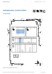
3.1 Routing details<br />
Print-no. 250 020 1<br />
08/2009<br />
For installing the electronic automatic locking system it is required to rout out for<br />
standard three-point locking system and additionally the motor housing, as shown in<br />
the following diagrams.<br />
2084[82.047"]<br />
260[10.236"]<br />
340[13.386"]<br />
736[28.976"]<br />
754[29.685"]<br />
61[2.402"]<br />
5[0.197"]<br />
78[3.071"]<br />
60[2.362"]<br />
41[1.614"]<br />
230<br />
[9.055"]<br />
croppable<br />
Aug. <strong>Winkhaus</strong> GmbH & Co. KG · Berkeser Str. 6 · D-98617 Meiningen · www.winkhaus.de<br />
Subject to technical changes<br />
113[4.449"]<br />
47[1.850"]<br />
53[2.086"]<br />
D[Backset]<br />
173[6.811"]<br />
18[0.709"]<br />
63[2.480"]<br />
123[4.843"]<br />
180<br />
[7.087"]<br />
croppable<br />
Figure 3.1-1: Dimensions for the electronic automatic locking system<br />
1050[41.339"]<br />
195[7.677"]<br />
226[8.898"]<br />
663[26.102"]<br />
827[32.559"]<br />
2105[82.874"]<br />
+ NOTICE!<br />
Important for wood/<br />
composite entrance<br />
doors: Please enlarge<br />
the routing for the additional<br />
lock housings<br />
up to 47 mm [1.850”]!<br />
General<br />
information<br />
1<br />
Important<br />
information<br />
Installation<br />
2<br />
Product<br />
description<br />
3<br />
4<br />
Operation<br />
Programming<br />
5<br />
Maintenance<br />
and care<br />
6<br />
Errors<br />
Troubleshooting<br />
7<br />
Technical<br />
specifications<br />
8<br />
Accessories
1<br />
2<br />
3<br />
4<br />
5<br />
6<br />
7<br />
8<br />
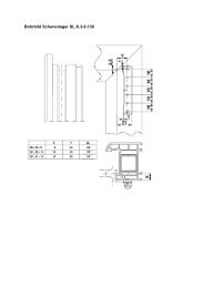
<strong>Operating</strong> <strong>Manual</strong> EAV 18<br />
Figure 3.1-2: Location of the motor housing for the electronic automatic locking system<br />
Aug. <strong>Winkhaus</strong> GmbH & Co. KG · Berkeser Str. 6 · D-98617 Meiningen · www.winkhaus.de<br />
Subject to technical changes<br />
Print-no. 250 020 1<br />
08/2009<br />
Figure 3.1-3: Location of the main lock housing for the electronic automatic locking system<br />
+ NOTICE!<br />
a) The routing for the main lock housing must be 16 mm [0.630”] as<br />
minimum to provide for free motion of the drive rod! Check the door euro<br />
groove for sprue so that the free motion of the rod is not impeded!<br />
b) It is imperative to use always with a Lever/fixed pad handle set (lever<br />
inside, door knob outside).
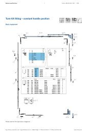
<strong>Operating</strong> <strong>Manual</strong> EAV 19<br />
3.2 Cable transition KÜ-T-STV (plug-in)<br />
∅13 [0.512"]<br />
distance approx. 208<br />
(under pre-tension!)<br />
11 [0.433"]<br />
Sash part<br />
11 [0.433"]<br />
3<br />
16 [0.630"] resp.<br />
20 [0.787"]<br />
Figure 3.2-1: Routing dimensions for cable transition KÜ-T-STV<br />
1<br />
2<br />
9 [0.354"]<br />
∅6 [0.236"]<br />
Cover plate<br />
9 [0.354"]<br />
16 [0.630"]<br />
Frame part<br />
16 [0.630"]<br />
Aug. <strong>Winkhaus</strong> GmbH & Co. KG · Berkeser Str. 6 · D-98617 Meiningen · www.winkhaus.de<br />
Subject to technical changes<br />
22 [0.866"]<br />
6.5 [0.256"]<br />
Print-no. 250 020 1<br />
08/2009<br />
Installation sequence:<br />
Frame part:<br />
• Drill a hole with a Ø of 6 mm<br />
[0.236”] through the door frame.<br />
• Pass the cable through the door<br />
frame.<br />
• Fasten the part with the fitting<br />
screw 1 having a Ø of 4 x 25 mm<br />
[0.984”].<br />
Sash part:<br />
• Drill a hole of Ø 13 mm [0.512”]<br />
(or drill a hole 2 x Ø 13 mm resp.<br />
oblong hole + cover plate) through<br />
the euro groove up to the glass<br />
groove (approx 208 mm vertically<br />
over the frame part drill hole of<br />
Ø 6 mm)<br />
CAUTION! The clearance hole must be burr-free. The spring must be kept under<br />
a slight pre-tension even with the door being closed.<br />
• Pass the cable with the plug for the motor housing through the door sash.<br />
• Insert the end of the spring into the hole in the door sash.<br />
• Recommendation: for wooden doors (if applicable also for PVCu/Vinyl or aluminum<br />
doors) use the cover plate F16/F20, to hide the routering for the cable hole,<br />
and to prevent cable damage. The routing for this cable hole should be approx<br />
50 x 90 mm [1.968 x 3.543”].<br />
• Fasten the part in the fitting nut by using the fixing screws 2 having a Ø of<br />
4 x 25 mm [0.984”].<br />
• Install the cable for example within the glazing chamber towards the motor<br />
housing; install the rest of the cable for example within the hollow section.<br />
General<br />
information<br />
1<br />
Important<br />
information<br />
Installation<br />
2<br />
Product<br />
description<br />
3<br />
4<br />
Operation<br />
Programming<br />
5<br />
Maintenance<br />
and care<br />
6<br />
Errors<br />
Troubleshooting<br />
7<br />
Technical<br />
specifications<br />
8<br />
Accessories
1<br />
2<br />
3<br />
4<br />
5<br />
6<br />
7<br />
8<br />
<strong>Operating</strong> <strong>Manual</strong> EAV 20<br />
+ NOTICE!<br />
Aug. <strong>Winkhaus</strong> GmbH & Co. KG · Berkeser Str. 6 · D-98617 Meiningen · www.winkhaus.de<br />
Subject to technical changes<br />
Print-no. 250 020 1<br />
08/2009<br />
Provide cable slack of about 3 - 5 cm [1.181 - 1.969”] for the<br />
spring tension behind the sash part of the cable transition.<br />
• Complete the plug-in connection after putting the door on its hinges.<br />
• Fix the plug with the fitting screw 3 having a Ø of 4 x 25 mm [0.984”].<br />
CAUTION! Release the second retaining screw 3 (e. g. during the installation<br />
of the door frame into the reveal) when unhinge the door sash!<br />
Insulate the wires not used!<br />
Cover plate F16 or F20 for KÜ-T-STV<br />
For wooden doors use the cover plate F16/F20, to hide the routering for the cable hole,<br />
and to prevent cable damage. The routing for this wire hole should be approx 50 x<br />
90 mm [1.968 x 3.543”].<br />
290 [11.417"]<br />
90 [3.543"]<br />
16 [0.630"]<br />
(20 [0.787"])<br />
230 [9.055"]<br />
Figure 3.2-2: Routing dimensions for cable transition KÜ-T-STV<br />
100 [3.937"]<br />
F16=R8 [0.315"]<br />
F20=R10 [0.394"]<br />
116 [4.567"]<br />
(120 [4.724"])<br />
50 [1.968"]<br />
3 [0.118"]<br />
12 [0.472"]<br />
50 [1.968"]<br />
3 [0.118"]<br />
16 [0.630"]<br />
16 [0.630"]<br />
9 [0.354"]<br />
Cover plate F16<br />
16 [0.630"]<br />
9 [0.354"]<br />
20 [0.787"]<br />
Cover plate F20<br />
Sash part<br />
Sash part
<strong>Operating</strong> <strong>Manual</strong> EAV 21<br />
3.3 Installations<br />
Print-no. 250 020 1<br />
08/2009<br />
DANGER!<br />
The installation of electrical equipment requires expertise, thus such work<br />
should only be carried out by qualified electricians.<br />
DANGER!<br />
Generally assemble and install only with the power off!<br />
CAUTION!<br />
The Door must easily lock mechanically before checking the electric function!<br />
If you connect an intercom system take care that the button of this<br />
system is designed as a potential free contact! External voltage must not be<br />
transmitted from the intercom system to the lock!<br />
If the operating voltage has been applied (start-up), the motor brings the locking points<br />
into the neutral position.<br />
Aug. <strong>Winkhaus</strong> GmbH & Co. KG · Berkeser Str. 6 · D-98617 Meiningen · www.winkhaus.de<br />
Subject to technical changes<br />
General<br />
information<br />
1<br />
Important<br />
information<br />
Installation<br />
2<br />
Product<br />
description<br />
3<br />
4<br />
Operation<br />
Programming<br />
5<br />
Maintenance<br />
and care<br />
6<br />
Errors<br />
Troubleshooting<br />
7<br />
Technical<br />
specifications<br />
8<br />
Accessories
1<br />
2<br />
3<br />
4<br />
5<br />
6<br />
7<br />
8<br />
<strong>Operating</strong> <strong>Manual</strong> EAV 22<br />
3.3.1 General connection diagram<br />
Recommendation: flush-type box or junction box for cable connection<br />
to/from the motor housing or cable transition<br />
4 5 free<br />
3 2 1<br />
e. g. Connector block (via<br />
electrical contractor)<br />
1 - white<br />
2 - brown<br />
3 - green<br />
4 - yellow<br />
5 - grey<br />
„Open“<br />
button *<br />
other<br />
button *<br />
access control<br />
system *<br />
other access<br />
control systems *<br />
Figure 3.3.1-1: General connection diagram<br />
L<br />
N PE<br />
power supply<br />
12V DC/2A<br />
(plus) (minus)<br />
automatic<br />
door opener<br />
(optional)<br />
Aug. <strong>Winkhaus</strong> GmbH & Co. KG · Berkeser Str. 6 · D-98617 Meiningen · www.winkhaus.de<br />
Subject to technical changes<br />
Print-no. 250 020 1<br />
** cable of 2 x 0.8 mm², max. 100 m<br />
08/2009<br />
** cable of 2 x 0.8 mm², length of max. 40 m<br />
[43.744 yd]<br />
flush-type box or junction box<br />
length and cross section: specification by<br />
the manufacturer of automatic door opener<br />
[109.36 yd] (up to the last access control<br />
system/up to the last open button)<br />
* with potential free contact<br />
** no necessary screened cable
<strong>Operating</strong> <strong>Manual</strong> EAV 23<br />
3.4 Access control system transponder set<br />
Aug. <strong>Winkhaus</strong> GmbH & Co. KG · Berkeser Str. 6 · D-98617 Meiningen · www.winkhaus.de<br />
Subject to technical changes<br />
Print-no. 250 020 1<br />
08/2009<br />
Prerequisites for installation:<br />
• The transponder signal is processed in the reader/control unit.<br />
• This unit has to be installed in a standard flush-type box inside the building (close<br />
to the door).<br />
+ NOTICE!<br />
Should you want to accommodate the control unit and button in the same<br />
flush-type box, this must have a depth of 65 mm [2.559”].<br />
• Unless you use a button beside the door, you will have to install a flush-type box<br />
with a filler panel for the reader unit.<br />
DANGER!<br />
For safety reasons, do not install it in a flush-type box with a 230 V switch or<br />
socket outlet!<br />
• The transponder antenna is located in a housing for exposed installations and is to<br />
be installed in a weatherproof zone outside the entrance door.<br />
• Do not install the antenna directly on metal as its range could be decreased drastically.<br />
• Do not install any other antenna within a radius of 1 m [1.094 yd]!<br />
+ NOTICE!<br />
If you plan installations on a metal substructure, you will have to use a wooden<br />
board and spacer bolts, if applicable, or large bore holes to ensure the<br />
proper function of the antenna! To test the scanning performance, you may<br />
have to tentatively install it on site, if applicable!<br />
• Connect the cable of the antenna to the reader/control unit.<br />
• We recommend: Lay a reserve pipe from the antenna to the reader unit.<br />
General<br />
information<br />
1<br />
Important<br />
information<br />
Installation<br />
2<br />
Product<br />
description<br />
3<br />
4<br />
Operation<br />
Programming<br />
5<br />
Maintenance<br />
and care<br />
6<br />
Errors<br />
Troubleshooting<br />
7<br />
Technical<br />
specifications<br />
8<br />
Accessories
1<br />
2<br />
3<br />
4<br />
5<br />
6<br />
7<br />
8<br />
<strong>Operating</strong> <strong>Manual</strong> EAV 24<br />
Figure 3.4-1: Terminal assignment of the transponder reader<br />
to/from the motor housing<br />
or cable transition<br />
e. g. Connector<br />
block (via electrical<br />
contractor)<br />
white<br />
brown<br />
green<br />
yellow<br />
grey<br />
cable of 2 x 0.8 mm²,<br />
length of max. 40 m<br />
[43.744 yd]<br />
(plus) (minus)<br />
power supply<br />
12V DC/2A<br />
L<br />
N PE<br />
Figure 3.4-2: Installation of the transponder reader<br />
230V/50Hz<br />
No. Terminals<br />
1 „12V DC“<br />
2 „0V DC“<br />
3 serial interface<br />
4 serial interface<br />
5 antenna<br />
6 antenna<br />
7 potential free contact C<br />
8 potential free contact NO<br />
antenna<br />
„Open“<br />
button<br />
Recommendation:<br />
flush-type box or junction<br />
box for cable connection<br />
Aug. <strong>Winkhaus</strong> GmbH & Co. KG · Berkeser Str. 6 · D-98617 Meiningen · www.winkhaus.de<br />
Subject to technical changes<br />
Print-no. 250 020 1<br />
08/2009<br />
cable of 2 x 0.8 mm², length of max. 100 m<br />
[109.36 yd] (up to the last open button/up<br />
to the last access control system)<br />
automatic<br />
door opener<br />
(optional)<br />
antenna cable readymade,<br />
2.5 m [2.734 yd]<br />
fixed at the antenna,<br />
cable terminals with<br />
wire and bushes<br />
length and cross section: specification by<br />
the manufacturer of automatic door opener
<strong>Operating</strong> <strong>Manual</strong> EAV 25<br />
3.5 Access control system wireless remote control<br />
Aug. <strong>Winkhaus</strong> GmbH & Co. KG · Berkeser Str. 6 · D-98617 Meiningen · www.winkhaus.de<br />
Subject to technical changes<br />
Print-no. 250 020 1<br />
08/2009<br />
Prerequisites for installation:<br />
• To ensure the reliable performance, the position of the wireless receiver is of utmost<br />
importance for the received power.<br />
• Do not install it at or nearby sources of possible interference (e.g. EDP/high-performance<br />
power distributor).<br />
• To prevent manipulation of the receiver we recommend installing the receiver on<br />
the inner side of the door!<br />
3.5.1 Wireless remote control set<br />
Installation sequence:<br />
• Install the wireless receiver in a standard flush-type box on the inside.<br />
• Unless you use a switch or button beside the door; you will have to provide a flushtype<br />
box with a filler panel for the wireless receiver.<br />
+ NOTICE!<br />
If you use the flush-type box of the button, the box will have to be<br />
65 mm [2.559”] deep!<br />
DANGER! For safety reasons, you are not permitted to install it in a flushtype<br />
box with a 230 V switch or socket outlet!<br />
• Connect the terminals 2 through 5 of the wireless receiver as described in the table<br />
below.<br />
8<br />
9<br />
10<br />
11<br />
12<br />
13<br />
1 2 3 4 5 6 7<br />
Figure 3.5.1-1: Terminal assignment of the wireless receiver<br />
No. Terminals<br />
1 „Break contact (NC)“, is not required<br />
2 connect „Contact (C)“ - to the green wire at the<br />
cable transition<br />
3 connect „Make contact (NO)“ - to terminal 4 of<br />
the wireless receiver (+ 12V DC)<br />
4 connect „12V DC or 24V DC“ - with the white<br />
wire of the cable transition + terminal 2 of the<br />
wireless receiver<br />
5 Connect „0V DC“ - with the brown wire of the<br />
cable transition<br />
6 „Auxiliary antenna/ANT“ (not required)<br />
7 „Auxiliary antenna/GND“ (not required)<br />
General<br />
information<br />
1<br />
Important<br />
information<br />
Installation<br />
2<br />
Product<br />
description<br />
3<br />
4<br />
Operation<br />
Programming<br />
5<br />
Maintenance<br />
and care<br />
6<br />
Errors<br />
Troubleshooting<br />
7<br />
Technical<br />
specifications<br />
8<br />
Accessories
1<br />
2<br />
3<br />
4<br />
5<br />
6<br />
7<br />
8<br />
<strong>Operating</strong> <strong>Manual</strong> EAV 26<br />
No. Name No. Name<br />
8 „P1 button“ 11 „buzzer“<br />
9 „green LED“ 12 „relay“<br />
10 „red LED“ 13 „jumper“ 12V/24V<br />
to/from the motor housing<br />
or cable transition<br />
e. g. Connector<br />
block (via electrical<br />
contractor)<br />
white<br />
brown<br />
green<br />
yellow<br />
grey<br />
cable of 2 x 0.8 mm²,<br />
length of max. 40 m<br />
[43.744 yd]<br />
Figure 3.5.1-2: Installing the wireless receiver<br />
(plus) (minus)<br />
power supply<br />
12V DC/2A<br />
L<br />
N PE<br />
230V/50Hz<br />
Aug. <strong>Winkhaus</strong> GmbH & Co. KG · Berkeser Str. 6 · D-98617 Meiningen · www.winkhaus.de<br />
Subject to technical changes<br />
Print-no. 250 020 1<br />
„Open“<br />
button<br />
08/2009<br />
cable of 2 x 0.8 mm², length<br />
of max. 100 m [109.36 yd]<br />
(up to the last access control<br />
system/up to the last open<br />
button)<br />
automatic<br />
door opener<br />
(optional)<br />
length and cross section: specification<br />
by the manufacturer<br />
of automatic door openers<br />
Recommendation:<br />
flush-type box or junction<br />
box for cable connection
<strong>Operating</strong> <strong>Manual</strong> EAV 27<br />
12V = delivery status 24V<br />
Figure 3.5.1-3: Adjustment of the jumper for voltage selection<br />
Print-no. 250 020 1<br />
08/2009<br />
• The default setting of the jumper is 12V.<br />
• The wireless receiver can be adjusted from 12V to 24V via the jumper.<br />
+ NOTICE! Check the proper position of the jumper before starting operation!<br />
3.5.2 Wireless receiver (separate)<br />
Separate wireless receiver for additional applications, such as garage door control<br />
units.<br />
80 [3.150“]<br />
Figure 3.5.2-1: Installing the wireless receiver<br />
80 [3.150“]<br />
Aug. <strong>Winkhaus</strong> GmbH & Co. KG · Berkeser Str. 6 · D-98617 Meiningen · www.winkhaus.de<br />
Subject to technical changes<br />
51 [2.008“]<br />
Installation sequence:<br />
• Remove the cover of the housing.<br />
• Fasten the housing with screws.<br />
• Push in the rubber plug (see Figure 3.5.2-1).<br />
• Insert the circuit board of the remote according to figure 3.5.2-2 and connect it to the<br />
control of the additional application (for example to the garage door control unit).<br />
General<br />
information<br />
1<br />
Important<br />
information<br />
Installation<br />
2<br />
Product<br />
description<br />
3<br />
4<br />
Operation<br />
Programming<br />
5<br />
Maintenance<br />
and care<br />
6<br />
Errors<br />
Troubleshooting<br />
7<br />
Technical<br />
specifications<br />
8<br />
Accessories
1<br />
2<br />
3<br />
4<br />
5<br />
6<br />
7<br />
8<br />
<strong>Operating</strong> <strong>Manual</strong> EAV 28<br />
+ NOTICE!<br />
Aug. <strong>Winkhaus</strong> GmbH & Co. KG · Berkeser Str. 6 · D-98617 Meiningen · www.winkhaus.de<br />
Subject to technical changes<br />
Print-no. 250 020 1<br />
08/2009<br />
Do follow the relevant installation instructions of the additional<br />
applications!<br />
• Put the cover back on the housing and lock and screw it down.<br />
1<br />
2<br />
3<br />
4<br />
5<br />
Figure 3.5.2.-2: Terminal assignment of the circuit board of the receiver<br />
No. Name No. Name<br />
1 „JP1 jumper“ 4 „red LED“<br />
2 „P1 button“ 5 „green LED“<br />
3 „K4 relay“<br />
No. Terminals<br />
8, 9 NO relay K4 - non-operated contact is<br />
open, it closes by activating per remote<br />
control<br />
9, 10 NC relay K4 - non-operated contact is<br />
close, it opens by activating per remote<br />
control<br />
11, 12 „12V AC/DC“<br />
11, 13 „24V AC/DC“<br />
14 „Antenna“<br />
15 „Screen“<br />
• You can set the K4 relay as ON/OFF or as an impulse via the JP1 jumper (see<br />
figure 3.5.2-3). The setting depends on the control unit which is to be triggered by<br />
the receiver.<br />
JP1 = ON<br />
K4 ON/OFF<br />
Figure 3.5.2-3: Setting the K4 relay<br />
• Relay remains active after being activated<br />
by remote control.<br />
• Deactivation by actuating the remote<br />
control once more.<br />
JP1 = OFF<br />
K4 impulse<br />
• Relay becomes briefly active after<br />
being activated by remote control and<br />
after about 1 sec. it will be deactivated<br />
automatically.
<strong>Operating</strong> <strong>Manual</strong> EAV 29<br />
3.6 Non-<strong>Winkhaus</strong> access control system<br />
3.6.1 Non-<strong>Winkhaus</strong> access control system general<br />
Aug. <strong>Winkhaus</strong> GmbH & Co. KG · Berkeser Str. 6 · D-98617 Meiningen · www.winkhaus.de<br />
Subject to technical changes<br />
Print-no. 250 020 1<br />
08/2009<br />
Please observe the following instructions when using other than the precalled systems<br />
to control the electronic automatic locking system (e. g. transponder set, wireless remote<br />
control):<br />
• If several appliances (like access control + EAV) are operated together in the same<br />
door, you can use a common power supply with min. 1,5A for EAV additionally the<br />
power requirement of the access control system. For this you need a stabilized<br />
12V DC direct current (chapter 2: product description power supply).<br />
• Ensure that the decontrol signal takes place over a potential-free contact when<br />
using non-<strong>Winkhaus</strong> access control systems.<br />
If required use a coupling relay for realizing this.<br />
3.6.2 Non-<strong>Winkhaus</strong> access control system finger scanner ekey home<br />
integra<br />
Prerequisites for installation:<br />
• The described access control system ekey home integra have to be installed into<br />
the door sash.<br />
• If parallel to the access control another open signal (potential-free signal: e. g.<br />
„Open“ button, intercom, ...) should be used for unlocking, then it is possible via the<br />
cable transition KÜ-T-integra-EAV 1 (see figure: 3.6.1-1, detail B è connection<br />
grey/brown).<br />
Installation sequence:<br />
• Plug-in the cable of the cable transition KÜ-T-integra-EAV 1 with 8-pole plug at<br />
the control unit ekey home integra 2 (terminal X1).<br />
• Assembly connection between control unit ekey home integra 2 and finger scanner<br />
ekey home integra 3 via cable type A ekey home integra 6 with double<br />
sided plugs (terminal X3).<br />
+ NOTICE!<br />
Control unit ekey home integra, finger scanner ekey home integra,<br />
cable type A ekey home integra included in standard delivery ekey.<br />
General<br />
information<br />
1<br />
Important<br />
information<br />
Installation<br />
2<br />
Product<br />
description<br />
3<br />
4<br />
Operation<br />
Programming<br />
5<br />
Maintenance<br />
and care<br />
6<br />
Errors<br />
Troubleshooting<br />
7<br />
Technical<br />
specifications<br />
8<br />
Accessories
1<br />
2<br />
3<br />
4<br />
5<br />
6<br />
7<br />
8<br />
<strong>Operating</strong> <strong>Manual</strong> EAV 30<br />
Aug. <strong>Winkhaus</strong> GmbH & Co. KG · Berkeser Str. 6 · D-98617 Meiningen · www.winkhaus.de<br />
Subject to technical changes<br />
Print-no. 250 020 1<br />
08/2009<br />
• Assembly connection between control unit ekey home integra 2 and motor<br />
housing EAV 4 . For this connect the wires of the cable of 2 m (included in delivery<br />
of the integra - EAV 5 ) with terminal X6 (see figure: 3.6.1-1, detail A). After<br />
this plug-in the blue plug into the motor housing.<br />
figure 3.6.1-1: wiring EAV and finger scanner ekey home integra<br />
No. Name<br />
1 separable cable transition KÜ-T-integra-EAV<br />
2 control unit ekey home integra<br />
3 finger scanner ekey home integra<br />
6<br />
5<br />
2<br />
3<br />
4<br />
1<br />
green<br />
brown<br />
white<br />
3<br />
2<br />
1<br />
X3<br />
X6<br />
X1<br />
X1: supply line from the cable transition<br />
to the control unit via 8-pole plug<br />
X3: connection from the finger scanner<br />
of the control unit via plug<br />
X6: screwing terminal, connection to the<br />
motor housing (relay 1)<br />
1 = white supply +<br />
2 = brown supply -<br />
3 = green switching pulse<br />
detail A: control unit ekey home integra<br />
white + 12V DC<br />
brown - 0V (2A)<br />
green<br />
yellow<br />
grey<br />
green/yellow = output relay 2 at<br />
integra 2 (potential-free contact)<br />
grey/brown = input for external<br />
potential-free contact (e. g. unlocking<br />
via intercom/button)<br />
NOTICE: max. 40 m extendable<br />
detail B: connections KÜ-T-integra-EAV<br />
No. Name<br />
4 motor housing EAV<br />
5 cable integra - EAV (2 m)<br />
6 cable Typ „A“ ekey home integra (2 or 4 m)
<strong>Operating</strong> <strong>Manual</strong> EAV 31<br />
3.6.2.1 Control of additional applications (only integra 2)<br />
Aug. <strong>Winkhaus</strong> GmbH & Co. KG · Berkeser Str. 6 · D-98617 Meiningen · www.winkhaus.de<br />
Subject to technical changes<br />
Print-no. 250 020 1<br />
08/2009<br />
• The control of a additional application (e. g. garage door, alarm system) takes place<br />
via the second relay of the integra 2.<br />
• This potential-free signal can be tapped at the wires green/yellow of the frame part<br />
of the separable cable transition KÜ-T-integra-EAV 1 (see figure 3.6.1-1, detail B<br />
è connection green/yellow).<br />
3.6.2.2 Control of automatic door opener (integra 1 and 2)<br />
• You have to use a second cable transition (KÜ-T-STV-FL 3,5 m, item no. 4930427)<br />
when using a EAV with control of automatic door opener.<br />
• You have to use the cable 3,5 m of the second cable transition (sash part) instead<br />
of the cable integra - EAV 2 m 5 .<br />
• Make a connection from the motor housing EAV (blue plug) to the control unit ekey<br />
home integra (length of min. 2 m) via this cable.<br />
If necessary disconnect the cable respectively remove the cable covering.<br />
• You have to mount connector sleeves onto the wires white, brown, green and connect<br />
them at terminal X6 as described on detail A.<br />
• You have to connect the two remaining wires (yellow/grey) of the motor housing<br />
with the homochromatic wires (yellow/grey) of the second cable transition.<br />
• Reconnect the cable by using wire connectors if it was disconnected.<br />
+ NOTICE! For further information on ekey home integra please contact company<br />
ekey (www.ekey.net).<br />
General<br />
information<br />
1<br />
Important<br />
information<br />
Installation<br />
2<br />
Product<br />
description<br />
3<br />
4<br />
Operation<br />
Programming<br />
5<br />
Maintenance<br />
and care<br />
6<br />
Errors<br />
Troubleshooting<br />
7<br />
Technical<br />
specifications<br />
8<br />
Accessories
1<br />
2<br />
3<br />
4<br />
5<br />
6<br />
7<br />
8<br />
<strong>Operating</strong> <strong>Manual</strong> EAV 32<br />
4 Operation/Programming<br />
4.1 Electronic automatic locking system<br />
4.1.1 Locking and unlocking<br />
Aug. <strong>Winkhaus</strong> GmbH & Co. KG · Berkeser Str. 6 · D-98617 Meiningen · www.winkhaus.de<br />
Subject to technical changes<br />
Print-no. 250 020 1<br />
08/2009<br />
Locking:<br />
• Even when closing the door it is automatically locked by two massive hooks and<br />
the latch in the main lock housing.<br />
• Additional protection is provided by manual locking: one rotation of the key<br />
(1 x 360°) causes the dead bolt in the main lock housing to be thrown.<br />
Opening the door from outside:<br />
• Unlocking via the connected access control system (e. g. Transponder chip, wireless<br />
remote control) or with a key.<br />
+ NOTICE! The main dead bolt for additional protection must be unlocked by<br />
keys in any case.<br />
Opening the door from inside, e. g. via:<br />
• the push-button<br />
• the intercom (potential free button!)<br />
• the handle or key (even possible in case of power failure)<br />
4.2 Electronic automatic door locking system with transponder<br />
4.2.1 Operation<br />
The reader unit controls and monitors the access to the door.<br />
• It is operated by means of transponder chips that work contactless.<br />
• Hold a programmed transponder chip within (0 - 8 cm, [0 - 3.150”]) of the<br />
antenna.<br />
• Once the transponder chip is close enough to where it can read the information,<br />
communication is established contact free.
<strong>Operating</strong> <strong>Manual</strong> EAV 33<br />
Aug. <strong>Winkhaus</strong> GmbH & Co. KG · Berkeser Str. 6 · D-98617 Meiningen · www.winkhaus.de<br />
Subject to technical changes<br />
Print-no. 250 020 1<br />
08/2009<br />
• The transponder data is transmitted to the reader unit via the antenna.<br />
• An acoustic signal at the reader unit will acknowledge the data transfer.<br />
• The reader checks whether this ttransponder chip is authorized to access and<br />
allows or denies access.<br />
Action Acoustic Signal U Result<br />
Door with transponder n n<br />
authorized<br />
chip „Open“<br />
short, short<br />
• After the enable time has elapsed, another fob can be recognized and evaluated.<br />
• If a transponder chip is unknown to the reader, it does not have access rights and<br />
access will be denied.<br />
Action Acoustic Signal U Result<br />
Door with transponder n nnnn<br />
not authorized<br />
chip „Open“<br />
short, long<br />
4.2.2 Programming<br />
Each transponder set is supplied with 2 programming cards. (programming card =<br />
green; delete-all card = red) These cards are programmed to this reader/control unit.<br />
Teach-in mode<br />
Programmierkarte<br />
Programming card: Set teach-in mode<br />
Ü Teach Transponder chip<br />
Action Acoustic Signal U Result<br />
Pass the programmable n<br />
teach-in mode<br />
card over the antenna short, every 0.5 seconds „active“<br />
General<br />
information<br />
1<br />
Important<br />
information<br />
Installation<br />
2<br />
Product<br />
description<br />
3<br />
4<br />
Operation<br />
Programming<br />
5<br />
Maintenance<br />
and care<br />
6<br />
Errors<br />
Troubleshooting<br />
7<br />
Technical<br />
specifications<br />
8<br />
Accessories
1<br />
2<br />
3<br />
4<br />
5<br />
6<br />
7<br />
8<br />
<strong>Operating</strong> <strong>Manual</strong> EAV 34<br />
+ NOTICE!<br />
Aug. <strong>Winkhaus</strong> GmbH & Co. KG · Berkeser Str. 6 · D-98617 Meiningen · www.winkhaus.de<br />
Subject to technical changes<br />
Print-no. 250 020 1<br />
08/2009<br />
If you do not swipe the transponder chip across the antenna for<br />
a period of 5 seconds, the teach-in mode will be stopped. The reader unit<br />
returns to operating mode.<br />
Action Acoustic Signal U Result<br />
Pass all the transponder nnnnn<br />
Transponder chips<br />
chips to be authorised in<br />
succession over the antenna<br />
for about 1 second „authorised“<br />
Pass all the transponder no acoustic signal memory over (250 trans-<br />
chips to be authorised in (no more transponder ponder chips have already<br />
succession over the antenna chips can be authorised) been programmed)<br />
Delete mode<br />
Gesamt<br />
Lösch-Karte<br />
Delete-all card: Delete mode „All transponder<br />
chips“ Ü Deletes all transponder<br />
chips<br />
CAUTION! By using the delete-all card all the transponder chips stored in the<br />
system will be deleted! The action of deleting all transponder chips is irrevocable<br />
once the process has been completed!<br />
You have to teach up to 250 new transponder chips from the start!<br />
The programming cards cannot open the door!<br />
Action Acoustic Signal U Result<br />
Pass the delete-all card nnnnn<br />
end of delete mode<br />
over the antenna<br />
for about 1 second „All transponder chips“<br />
+ NOTICE! All transponder chips have been deleted and the reader unit is at<br />
delivery status. The delete-all card and the programming card are saved,<br />
a transponder chip is not saved. In this state you cannot open the door via<br />
transponder chip or card; rather you will have to re-progamm the transponder<br />
chip.
<strong>Operating</strong> <strong>Manual</strong> EAV 35<br />
+ NOTICE!<br />
Print-no. 250 020 1<br />
08/2009<br />
Keep the programming cards at a safe place to prevent any kind of<br />
misuse. If you lose the cards, the reader unit will have to be exchanged in its<br />
entirety! Please contact customer service in such a case.<br />
4.3 Electronic automatic locking system with wireless remote control<br />
4.3.1 Operation<br />
• It is operated via the wireless remote controls working contactless.<br />
• The set of 3 wireless remote controls delivered have already been progammed<br />
(button A).<br />
• To trigger a signal, press the A button of a progammed remote control. The red LED<br />
will turn on and the door will be unlocked.<br />
4.3.2 Programming<br />
You can program the wireless remote control via the wireless remote control or the<br />
wireless receiver. We recommend programming it by using the wireless remote control.<br />
The programming per remote control is not possible for the wireless receiver for<br />
additional applications.<br />
Teaching a wireless remote control directly at the remote control (recommended)<br />
red LED<br />
+ NOTICE!<br />
button B<br />
button A<br />
Keep the buttons pressed until you hear the acoustic signal at the<br />
receiver!<br />
Aug. <strong>Winkhaus</strong> GmbH & Co. KG · Berkeser Str. 6 · D-98617 Meiningen · www.winkhaus.de<br />
Subject to technical changes<br />
General<br />
information<br />
1<br />
Important<br />
information<br />
Installation<br />
2<br />
Product<br />
description<br />
3<br />
4<br />
Operation<br />
Programming<br />
5<br />
Maintenance<br />
and care<br />
6<br />
Errors<br />
Troubleshooting<br />
7<br />
Technical<br />
specifications<br />
8<br />
Accessories
1<br />
2<br />
3<br />
4<br />
5<br />
6<br />
7<br />
8<br />
<strong>Operating</strong> <strong>Manual</strong> EAV 36<br />
Aug. <strong>Winkhaus</strong> GmbH & Co. KG · Berkeser Str. 6 · D-98617 Meiningen · www.winkhaus.de<br />
Subject to technical changes<br />
Print-no. 250 020 1<br />
08/2009<br />
* If no remote control has been programmed (for example after „delete-all“ function),<br />
it would apply to all remote controls. The teach-in mode can be started with<br />
any remote control.<br />
Deleting wireless remote controls directly via the remote control<br />
+ HINWEIS! Keep the buttons pressed until you hear the acoustic signal at the<br />
receiver!<br />
Partial deletion:<br />
Action Acoustic Signal U Result<br />
1) Press buttons A and B n<br />
teach-in mode<br />
(of a programmed remote<br />
control) simultaneously *<br />
brief<br />
„started“<br />
2) Press A button (of the nnnnnnnnn teach-in mode<br />
same remote control) continuous signal (as<br />
long as delete mode is<br />
„active“)<br />
„active“<br />
3) Press all buttons to be nnnn nnnn (pressed) button(s) is/are<br />
deleted in succession, as long continuous signal is „deleted“<br />
as the delete mode is „active“ briefly interrupted<br />
Delete-all:<br />
Action Acoustic Signal U Result<br />
1) Press buttons A and B n<br />
teach-in mode<br />
(of a programmed remote<br />
control) simultaneously<br />
short<br />
„started“<br />
2) Press A button (of the nnnnnnnnn teach-in mode<br />
same remote control) continuous signal<br />
(as long as the delete<br />
mode is „active“)<br />
„active“<br />
3) Press buttons A and B n n n<br />
memory of the receiver is<br />
(of a programmed remote short, 3 times<br />
„completely deleted“ (non<br />
control) simultaneously<br />
programmed remote control)
<strong>Operating</strong> <strong>Manual</strong> EAV 37<br />
Replacing the batteries in the wireless remote control<br />
Aug. <strong>Winkhaus</strong> GmbH & Co. KG · Berkeser Str. 6 · D-98617 Meiningen · www.winkhaus.de<br />
Subject to technical changes<br />
Print-no. 250 020 1<br />
08/2009<br />
• At the button ring hole, pull the colored battery cover from the bottom of the remote<br />
control outwards.<br />
• The battery compartment swings out.<br />
• Replace the batteries.<br />
• Insert two Lithium CR 2016.31 batteries.<br />
+ NOTICE! Pay attention to the correct polarity!<br />
ECO-WATCH! Properly dispose of the batteries as demanded by environmental<br />
regulation!<br />
Teaching wireless remote controls directly via the receiver<br />
8<br />
9<br />
10<br />
11<br />
12<br />
13<br />
8 „P1 button“<br />
9 „green LED“<br />
10 „red LED“<br />
11 „buzzer“<br />
12 „relay“<br />
13 „jumper“ 12V/24V<br />
• If the programming is performed via the receiver, this will have to be freely accessible.<br />
• Press the P1 button of the receiver until the green LED lights up.<br />
• Release the button.<br />
• Activate the desired button of the remote control while the LED is lit up<br />
• As long as the LED is lit, you can program additional remote control buttons.<br />
General<br />
information<br />
1<br />
Important<br />
information<br />
Installation<br />
2<br />
Product<br />
description<br />
3<br />
4<br />
Operation<br />
Programming<br />
5<br />
Maintenance<br />
and care<br />
6<br />
Errors<br />
Troubleshooting<br />
7<br />
Technical<br />
specifications<br />
8<br />
Accessories
1<br />
2<br />
3<br />
4<br />
5<br />
6<br />
7<br />
8<br />
<strong>Operating</strong> <strong>Manual</strong> EAV 38<br />
Aug. <strong>Winkhaus</strong> GmbH & Co. KG · Berkeser Str. 6 · D-98617 Meiningen · www.winkhaus.de<br />
Subject to technical changes<br />
Print-no. 250 020 1<br />
08/2009<br />
Display Memory full: The memory has been filled to capacity (max. 85 buttons), if the<br />
teach-in button of a new wireless remote control is used and both LED displays of the<br />
receiver flash simultaneously.<br />
Deleting wireless remote controls directly via the receiver<br />
Partial deletion:<br />
• Press and hold the P1 button of the receiver until the green LED lights up.<br />
• Release the button.<br />
• Press the button of the wireless remote control while the LED is lit up.<br />
• A programmed wireless remote control will be deleted automatically.<br />
• A wireless remote control that has not been programmed by this method will need<br />
a programming analogue „Teaching-in of wireless remote controls directly via the<br />
remote control“.<br />
Delete-all:<br />
• Press and hold the P1 button of the receiver until the green LED lights up.<br />
• Release the button.<br />
• Press the button again until the green and the red LED flash three times.<br />
• Now, all remote controls are deleted.<br />
ON/OFF mode:<br />
• The default setting of the relay of the receiver is „Pulse“.<br />
• You can program it as an ON/OFF relay for additional applications (specified by the<br />
respective application).<br />
• For this purpose, press the P1 button of the receiver until the green LED lights up.<br />
• Release the button again.<br />
• Press the P1 button once more.<br />
• The LED flashes and the relay is switched to the ON/OFF mode.<br />
• Use the same procedure to get to the pulse mode.<br />
• Then, the LED will be lit continuously.<br />
Displaying the occupied memory units:<br />
• Press and hold the P1 button of the receiver until the green LED lights up.
<strong>Operating</strong> <strong>Manual</strong> EAV 39<br />
• Keep the button pressed until the LED goes off.<br />
• Then release the button immediately.<br />
The display is a binary code: LED green = 1, LED red = 0<br />
Aug. <strong>Winkhaus</strong> GmbH & Co. KG · Berkeser Str. 6 · D-98617 Meiningen · www.winkhaus.de<br />
Subject to technical changes<br />
Print-no. 250 020 1<br />
4.4 Wireless receiver for additional applications<br />
(e. g. garage door control units)<br />
+ NOTICE!<br />
The programming of remote controls via this receiver is not possible.<br />
Programming via the wireless receiver (item no.: 2142897)<br />
1<br />
2<br />
3<br />
4<br />
5<br />
1 „JP1 jumper“<br />
2 „P1 button”<br />
3 „K4 relay ”<br />
4 „red LED”<br />
5 „green LED”<br />
08/2009<br />
The wireless receiver saves the button of the wireless remote control in the sequence<br />
entered.<br />
• To programm, press the P1 button of the circuit board of the wireless receiver.<br />
• The green LED lights up.<br />
• Release the P1 button.<br />
• Then, press the button of the wireless remote control you would like to save.<br />
• The LED turns off.<br />
• The desired button of the wireless remote control has been programmed.<br />
Deleting via the wireless receiver<br />
Partial deletion:<br />
• Press and hold the P1 button for about 2 seconds.<br />
• When the green LED lights up, release the P1 button.<br />
General<br />
information<br />
1<br />
Important<br />
information<br />
Installation<br />
2<br />
Product<br />
description<br />
3<br />
4<br />
Operation<br />
Programming<br />
5<br />
Maintenance<br />
and care<br />
6<br />
Errors<br />
Troubleshooting<br />
7<br />
Technical<br />
specifications<br />
8<br />
Accessories
1<br />
2<br />
3<br />
4<br />
5<br />
6<br />
7<br />
8<br />
<strong>Operating</strong> <strong>Manual</strong> EAV 40<br />
• Press the button of the wireless remote control you would like to delete.<br />
• The deletion of the button is signaled by the flashing LED.<br />
Aug. <strong>Winkhaus</strong> GmbH & Co. KG · Berkeser Str. 6 · D-98617 Meiningen · www.winkhaus.de<br />
Subject to technical changes<br />
Print-no. 250 020 1<br />
08/2009<br />
Delete-all:<br />
• Press and hold the P1 button until the green LED lights up.<br />
• Release the P1 button.<br />
• When the LED lights, press the P1 button again until both LED flash three times.<br />
The memory is full once 85 buttons have been saved in the wireless remote control.<br />
Now it is not possible to save additional wireless remote controls. This condition is indicated<br />
in the teach-in mode by both LED displays flashing simultaneously three times.<br />
5 Maintenance and care<br />
• Components of the door furniture relevant to security have to be checked for tightness<br />
and wear at regular intervals. If required, the retaining screws should be<br />
retightened and defective parts should be replaced.<br />
• Check the locking mechanism and smooth operation of the security lock at regular<br />
intervals (at least once every three months).<br />
• At least once a year - more frequently if under a higher stress factor - all moveable<br />
parts and all accessible sliding members of the locking system need to be lubricated<br />
with a light grease and checked for proper performance regarding mechanics<br />
and electronics.<br />
• You should only use neutral cleaning agents or care products that do not contain<br />
any abrasives in order to protect the anticorrosion coat of the door furniture.<br />
• Clean electronic parts only in a dry state.
<strong>Operating</strong> <strong>Manual</strong> EAV 41<br />
6 Errors/Causes/Troubleshooting<br />
Error Indication Possible cause Troubleshooting<br />
the door does not<br />
lock automatically<br />
the latch is<br />
„blocked“<br />
the door cannot be<br />
closed<br />
the motor does not<br />
function although<br />
voltage is applied at<br />
the door<br />
the door cannot<br />
be opened by the<br />
motor<br />
Hooks not engaged • the door is warped<br />
• the contact pressure is<br />
too high<br />
• the door has not been<br />
installed properly<br />
the door is not<br />
latched in the center<br />
location<br />
the hook latch is<br />
„blocked“ in the<br />
single keep<br />
the door cannot be<br />
opened<br />
the motor does not<br />
function<br />
Aug. <strong>Winkhaus</strong> GmbH & Co. KG · Berkeser Str. 6 · D-98617 Meiningen · www.winkhaus.de<br />
Subject to technical changes<br />
Print-no. 250 020 1<br />
08/2009<br />
• check the installation,<br />
and the keep adjustment<br />
and alignment<br />
• adjust the hinge plates<br />
• the routing in the • re-rout, if necessary<br />
area of the main lock<br />
housing is possibly not<br />
sufficient (chapter 3)<br />
• the door sash has<br />
not been mounted<br />
properly<br />
• no voltage supply via<br />
the cable transition<br />
• power failure<br />
• power supply is interrupted,<br />
e. g. at the<br />
cable transition<br />
• System not wired<br />
correctly<br />
the motor stops • the door is warped<br />
• the contact pressure is<br />
too high<br />
• the lock is too tight<br />
the motor functions<br />
but the door cannot<br />
be opened<br />
• the main bolt is<br />
unlocked via profile<br />
cylinder<br />
• <strong>Operating</strong> forces too<br />
high, faulty installation<br />
• at the single keep Ü<br />
change the height<br />
of the door keep (by<br />
using a screw driver)<br />
• check the cable transition<br />
(e. g. contacts,<br />
screwed joint for KÜ-<br />
T-STV)<br />
• unlock mechanically via<br />
profile cylinder/handle<br />
or lock via profile<br />
cylinder<br />
• Check main power<br />
supply to transformer<br />
• check KÜ, correct the<br />
plugin connection (see<br />
above)<br />
• Check entire system<br />
agains wiring diagram<br />
• adjust the door<br />
• check the operation via<br />
profile cylinder/handle<br />
• draw the main bolt<br />
back again via the<br />
profile cylinder<br />
• Check installation (keep<br />
alignment, air gap, etc.)<br />
General<br />
information<br />
1<br />
Important<br />
information<br />
Installation<br />
2<br />
Product<br />
description<br />
3<br />
4<br />
Operation<br />
Programming<br />
5<br />
Maintenance<br />
and care<br />
6<br />
Errors<br />
Troubleshooting<br />
7<br />
Technical<br />
specifications<br />
8<br />
Accessories
1<br />
2<br />
3<br />
4<br />
5<br />
6<br />
7<br />
8<br />
<strong>Operating</strong> <strong>Manual</strong> EAV 42<br />
Aug. <strong>Winkhaus</strong> GmbH & Co. KG · Berkeser Str. 6 · D-98617 Meiningen · www.winkhaus.de<br />
Subject to technical changes<br />
Print-no. 250 020 1<br />
08/2009<br />
Error<br />
Power failure when/<br />
during:<br />
Indication Possible cause Troubleshooting<br />
a) the door is locked • the door can be operated<br />
mechanically (profile<br />
cylinder/handle)<br />
b) the door is open,<br />
lock is unlocked<br />
c) the unlocking<br />
procedure<br />
EAV does not operate<br />
with remote but<br />
LED is illuminating.<br />
Does not operate<br />
with remote control,<br />
red LED is not illuminating.<br />
the door is possibly<br />
not held by the latch<br />
when the door is<br />
locked again, possibly<br />
the hook, main<br />
bolt do not lock<br />
completely<br />
• the motor is not in<br />
starting position<br />
• the motor is not in<br />
starting position<br />
Door doesn‘t open • Remote battery dead<br />
• Out of range to the<br />
remote control<br />
• Remote control not<br />
autthorized<br />
• close the door by prelocking<br />
the main bolt,<br />
if necessary<br />
• door can be operated<br />
mechanically (profile<br />
cylinder/handle), if<br />
motor has returned<br />
to starting position Ü<br />
completely functions<br />
• Replace battery in<br />
remote control<br />
• Operate remote control<br />
within 30 mtrs. (unostructed)<br />
• Check remote control<br />
programmed<br />
• Remote battery dead • Replace battery in<br />
remote control
<strong>Operating</strong> <strong>Manual</strong> EAV 43<br />
7 Technical specifications<br />
7.1 Power supply<br />
Aug. <strong>Winkhaus</strong> GmbH & Co. KG · Berkeser Str. 6 · D-98617 Meiningen · www.winkhaus.de<br />
Subject to technical changes<br />
Print-no. 250 020 1<br />
Primary voltage: 100 - 240V AC; 50/60Hz<br />
Secondary voltage: 12V DC stabilized<br />
Current: 2A<br />
Dimensions: 77 x 92 x 55 mm [3.031 x 3.622 x 2.165”]<br />
Weight: approx. 0.3 kg<br />
Installation: top hat mounting rail<br />
7.2 Antenna/Reader unit<br />
08/2009<br />
Dimensions (antenna): antenna housing: 90 x 90 x 13 mm [3.543 x 3.543<br />
x 0.512”], for exposed installation, cable is permanently<br />
installed<br />
Dimensions (reader): 45 x 45 x 22 mm [1.772 x 1.772 x 0.866”]<br />
Reading distance: between 0 and 8 cm [0 - 3.150”] (depending on<br />
the installation environment)<br />
Signalization: piezo-buzzer<br />
Data memory: max. 250 transponder chips<br />
Reader technique: Prox reader (EM 4102, Hitag)<br />
Power consumption: max. 100 mA<br />
Voltage: 12V AC/DC<br />
7.3 Wireless remote control<br />
Receiver type: Superheterodyne<br />
Modulation: AM/ASK<br />
Frequency: 433.92MHz<br />
Number of code combinations: 2 to the power of 64 („Rolling Code“)<br />
Frequency of the local oscillator: 6.6128MHz<br />
Intermediate frequency: 10.7MHz<br />
Sensitivity (to receive signals): -115dB<br />
General<br />
information<br />
1<br />
Important<br />
information<br />
Installation<br />
2<br />
Product<br />
description<br />
3<br />
4<br />
Operation<br />
Programming<br />
5<br />
Maintenance<br />
and care<br />
6<br />
Errors<br />
Troubleshooting<br />
7<br />
Technical<br />
specifications<br />
8<br />
Accessories
1<br />
2<br />
3<br />
4<br />
5<br />
6<br />
7<br />
8<br />
<strong>Operating</strong> <strong>Manual</strong> EAV 44<br />
Aug. <strong>Winkhaus</strong> GmbH & Co. KG · Berkeser Str. 6 · D-98617 Meiningen · www.winkhaus.de<br />
Subject to technical changes<br />
Print-no. 250 020 1<br />
08/2009<br />
Input impedance: 50ohm<br />
Maximum memory capacity: max. 85 buttons<br />
Power supply: 12/24V AC/DC<br />
Closed-circuit current: 10mA<br />
On-load current: 23mA<br />
Number of relays: 1 (NO-NC), output 24V A<br />
Dimensions (receiver): 44 x 33 x 17 mm [1.732 x 1.299 x 0.669”]<br />
Range: max. 30 meters [32.808 yd] (unobstructed area)<br />
200 meters [218.72 yd] with antenna<br />
Remote control<br />
Number of operations: 2 channel<br />
Power supply: Lithium CR 2016.31 battery<br />
Service life of batteries: 18 - 24 months<br />
Power consumption: 13mA<br />
Frequency: 433.92MHz<br />
Number of code combinations: 2 to the power of 64 (as „Rolling Code“)<br />
Modulation: AM/ASK<br />
Rated output E.R.P.: 50 - 100 µW<br />
Range in an unobstructed area: max. 30 m [32.808 yd]<br />
Dimensions: 61 x 36 x 16 mm [2.402 x 1.417 x 0.630”]<br />
Wireless receiver (separate)<br />
Receiver type: Superheterodyne<br />
Modulation: AM/ASK<br />
Frequency: 433.92MHz<br />
Frequency of the local oscillator: 6.6128MHz<br />
Intermediate frequency: 10.7MHz<br />
Sensitivity (to receive signals): 115dB<br />
Input impedance: 50Ohm<br />
Maximum memory capacity: 85 codes for remote control<br />
Power supply: 12/24V AC/DC<br />
Closed-circuit current: 15mA<br />
On-load current: 33/48mA
<strong>Operating</strong> <strong>Manual</strong> EAV 45<br />
Aug. <strong>Winkhaus</strong> GmbH & Co. KG · Berkeser Str. 6 · D-98617 Meiningen · www.winkhaus.de<br />
Subject to technical changes<br />
Print-no. 250 020 1<br />
Number of relays: (1 NO-NC)<br />
Power: 24W<br />
Dimensions: 80 x 80 x 50 mm [3.150 x 3.150 x 1.969”]<br />
7.4 Cable transition KÜ-T ...<br />
08/2009<br />
Measurements: total component length of about 222 mm [8.740”]<br />
Number of wires: 5<br />
Cross section of wires: 0.25 mm²<br />
Sash element: • STV-KÜ-T-STV-FL 2 m with cable 2 m<br />
[2.187 yd] + plug for motor housing<br />
• STV-KÜ-T-STV-FL 3,5 m with cable 3,5 m<br />
[3.829 yd] + plug for motor housing<br />
• STV-SET KÜ-T-integra-EAV FL 1 m with cable<br />
1 m, cable ends with 8-pole plug (for control<br />
unit ekey home integra)<br />
Frame element: with a cable of 4 m [4.374 yd]<br />
Max. voltage: 24V DC<br />
Max. switching current: 2A per connection line/wire<br />
General<br />
information<br />
1<br />
Important<br />
information<br />
Installation<br />
2<br />
Product<br />
description<br />
3<br />
4<br />
Operation<br />
Programming<br />
5<br />
Maintenance<br />
and care<br />
6<br />
Errors<br />
Troubleshooting<br />
7<br />
Technical<br />
specifications<br />
8<br />
Accessories
1<br />
2<br />
3<br />
4<br />
5<br />
6<br />
7<br />
8<br />
<strong>Operating</strong> <strong>Manual</strong> EAV 46<br />
8 Accessories<br />
Transponder chip<br />
Wireless remote control<br />
Wireless receiver<br />
Aug. <strong>Winkhaus</strong> GmbH & Co. KG · Berkeser Str. 6 · D-98617 Meiningen · www.winkhaus.de<br />
Subject to technical changes<br />
Print-no. 250 020 1<br />
08/2009<br />
Transponder chip (separate) as an extension to transponder set<br />
EAV (241 026 5).<br />
• form: key fob<br />
• color: blue<br />
STV-Transponder chip T01 blue 212 676 6<br />
Wireless remote control (separate) as an extension to the wireless<br />
remote control set (241 027 3).<br />
• color: dark grey/grey<br />
STV-Wireless remote control F01 dark grey 212 678 2<br />
Wireless receiver (separate); e. g. for coupling with the garage<br />
door control unit (the second button at the remote control can<br />
be used for this purpose)<br />
STV-Wireless receiver F01 214 289 7
<strong>Operating</strong> <strong>Manual</strong> EAV 47<br />
EC Declaration of Conformity<br />
For the products:<br />
Electronic Automatic Locking System<br />
in the design:<br />
Safety door locking system AV2 + motor control EAV 1<br />
(mounted/not mounted)<br />
Aug. <strong>Winkhaus</strong> GmbH & Co. KG · Berkeser Str. 6 · D-98617 Meiningen · www.winkhaus.de<br />
Subject to technical changes<br />
Print-no. 250 020 1<br />
08/2009<br />
we shall hereby certify that they conform to the requirements and directives established<br />
and stipulated by the Council on the Harmonization of Legal Regulations of Member<br />
States regarding Electromagnetic Compatibility (89/336/EEC).<br />
The following standards have been applied to assess the electromagnetic compatibility<br />
of the product:<br />
Emitted interference according to: EN 61000 - 6 - 3<br />
Immunity to interference according to: EN 61000 - 6 - 2<br />
This declaration is made on behalf of the manufacturer:<br />
Aug. <strong>Winkhaus</strong> GmbH & Co. KG<br />
Berkeser Str. 6<br />
D-98617 Meiningen<br />
Germany<br />
and authorized by:<br />
Meiningen, 09 July 2004 ..........................................................................................<br />
p.p.a. Dr. Warnow<br />
Title: Technical Director<br />
General<br />
information<br />
1<br />
Important<br />
information<br />
Installation<br />
2<br />
Product<br />
description<br />
3<br />
4<br />
Operation<br />
Programming<br />
5<br />
Maintenance<br />
and care<br />
6<br />
Errors<br />
Troubleshooting<br />
7<br />
Technical<br />
specifications<br />
8<br />
Accessories
Aug. <strong>Winkhaus</strong> GmbH & Co. KG<br />
Berkeser Straße 6<br />
D-98617 Meiningen<br />
T + 49 (0) 3693 950-0<br />
F + 49 (0) 3693 950-134<br />
www.winkhaus.de<br />
tuertechnik@winkhaus.de<br />
TV SB 0809 Print-no. 250 020 1 GB All rights reserved.