Flow-Converter UNICON®-DF Flow measurement with pulse ...
Flow-Converter UNICON®-DF Flow measurement with pulse ...
Flow-Converter UNICON®-DF Flow measurement with pulse ...

You also want an ePaper? Increase the reach of your titles
YUMPU automatically turns print PDFs into web optimized ePapers that Google loves.
<strong>Flow</strong>-<strong>Converter</strong> UNICON ® -<strong>DF</strong><br />
<strong>Flow</strong> <strong>measurement</strong> <strong>with</strong> <strong>pulse</strong> sensors<br />
Features<br />
M Measuring range programmable<br />
from -99999 ... 99999 Digit<br />
M Measuring unit programmable<br />
e.g. l/s; l/min; l/h; m³/s....;<br />
(US)gal/s....; (US)bar(rel)/s....<br />
M Totalizers programmable<br />
M Additional 2. measuring input<br />
M Output 4 ... 20mA, loop powered<br />
M Pulse-output for external evaluation<br />
M LCD-Text Display<br />
M 2 electronic alarm outputs, voltage free<br />
M Simulation mode for flow (manual operation)<br />
M Protection IP65<br />
General<br />
The <strong>Flow</strong>-<strong>Converter</strong> UNICON-<strong>DF</strong> is used in food technology, chemical and pharmaceutical industry and water<br />
technology. In connection <strong>with</strong> any type of <strong>pulse</strong> flow sensor the flow rate can be measured, displayed and<br />
converted in a 4 ... 20 mA signal. An additional feature is the summation function (totalizer). Using the alarm<br />
outputs a quantity dosage can be realized.<br />
Short information<br />
Programming The front panel keypad can be used to program all designated functions.<br />
Measurement value The measured values are averaged continuously over a period of 0.1 ... 10 s (programmable).<br />
This period limits the minimum input frequence, because at least two<br />
im<strong>pulse</strong>s must arrive <strong>with</strong>in.<br />
Totalizers 2 counters (totalizers) are available. The daily totalizer can be reset manually. Automatic<br />
reset takes place by cutting off power. The overall totalizer is zero voltage protected<br />
and can only be reset by a special code (password protection).<br />
Pulse output Allows an external summation of flow quantity.<br />
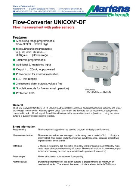
Fieldcase<br />
100x100x60 mm (BxHxT)<br />
Alarm outputs Switching performance of the alarm outputs is programmable as minimum or<br />
maximum function. The state of the alarm outputs is shown in the LCD-Display<br />
- 1 -
Technical data<br />
Power supply<br />
Supply voltage : 12 ... 30 V DC, loop powered<br />
Using Namur sensors or sensors <strong>with</strong> NPN- and PNP output <strong>with</strong> power demand<br />
> 5 V/ > 2 mA a separate supply is necessary (12 ... 30 V DC).<br />
Working temperature : -10 ... 55 °C<br />
Isolation : between analog output/alarm output 1/alarm output 2/im<strong>pulse</strong> output/external sensor<br />
supply<br />
Rated voltage : 500 V DC, between analog output/alarm output 1/alarm output 2/im<strong>pulse</strong> output/<br />
external sensor supply<br />
- conformity : EN50022, IEC61000-4-3/4/5<br />
Measuring input<br />
Typ : Inductive transmitter (coil), Namur-sensor or e.g. Hall-Sensor (rectangular <strong>pulse</strong>)<br />
programmable. Alternatively extern <strong>pulse</strong>s 0/5 ... 24 V DC.<br />
Input coil : switching threshold programmable from ±5 ... ±1000 mV<br />
Input NPN-Sensor : low level < 0.9 V , high level > 2.1 V pull-up-resistor 20 kΩ<br />
Input PNP-Sensor : low level < 0.9 V , high level > 2.1 V pull-down-resistor 20 kΩ<br />
Input Namur : low level < 1.4 mA , high level > 1.8 mA , hysteresis ca. 0.4 mA<br />
Input frequence : 0.1/10 ... 2000 Hz (depends on the programmed measuring interval)<br />
<strong>Flow</strong> output<br />
Current output : 4 ... 20 mA, external load RA [Ω] ≤<br />
Accuracy : < 0.1 % of the measuring value<br />
Temperature coefficient : < 0.01 %/ °C<br />
Supply voltage -12 V<br />
0,02 A<br />
Pulse output : 12 ... 30 V DC, load max. 60 mA, short circuit protected<br />
Pulse width : 100 ms<br />
Frequency : max. 5 Hz<br />
Quantity/Volume per <strong>pulse</strong> programmable from 1 ... 99999 digit<br />
Alarm outputs<br />
Transistor : 12 ... 30 V DC, load max. 60 mA, short circuit protected<br />
Voltage drop : < 2 V (at max. load)<br />
Display : LCD- dot matrix, 4.9 mm character height, 2 lines each 16 characters<br />
<strong>Flow</strong> : -99999 ... 0 ... 99999 digit, max 3 decimal points<br />
- Unit : l/s, l/min, l/h; m³/s, m³/min, m³/h; (US)gal/s, (US)gal/min,(US)gal/h; bar(rel)/s,<br />
bar(rel)/min, bar(rel)/h<br />
Totalizer : -9999999 ... 0 ... 9999999 digit, max. 3 decimal points<br />
- Unit : l, m³, (US)gallon, barrel<br />
- Storage : Daily totalizer not voltage safe<br />
Overall totalizer voltage safe<br />
Case : Field-case<br />
Material : case polyamide <strong>with</strong> fibre-glass PA6-GF/GK 15/15<br />
front foil polyester<br />
Dimensions : 100 x 100 x 60 mm (WxHxD)<br />
Weight : max. 360 g<br />
Electrical connection : Screw terminal pressure plate, 2.5 mm² flexible, 4 mm² wire<br />
Protection : IP65, terminals IP20 finger safe acc to German BGV A3<br />
- 2 -
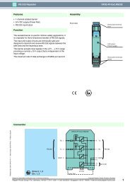
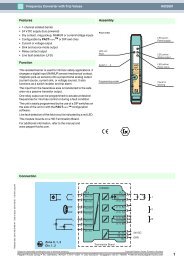
Legend (open lid)<br />
Dimensions<br />
Slide switch for<br />
write protection<br />
of EEPROM<br />
Terminals<br />
Sensor inputs<br />
Display contrast<br />
Outside brackets<br />
Cable gland M12x1.5 or<br />
2 x M12x1.5 for 2 measuring inputs<br />
cable diameter 3.0-6.5mm<br />
- 3 -<br />
Terminals outputs and<br />
external power supply<br />
Cable gland 1x M20x1.5<br />
For cable diameter 6.0-12.0mm,<br />
other glands on request
Connection diagram<br />
Terminals output<br />
Opto-coupler outputs<br />
max. 30 V DC/60 mA<br />
Alarm output<br />
AL2<br />
Alarm output<br />
AL1<br />
Pulse output Analog output**<br />
4 ... 20 mA<br />
Supply voltage*<br />
12-30 V DC/1 W<br />
* For supplying the converter use terminals (9) and (10) as shown. If the converter is used for monitoring<br />
only, terminals (9) and (10) must be connected direct to the supply voltage.<br />
** Separate supply voltage over the terminals 7 and 8 only when using Namur sensors (according to DIN<br />
EN60947) or sensors <strong>with</strong> NPN- or PNP output <strong>with</strong> power demand Ub > 5 V/> 2 mA.<br />
Terminals sensor inputs<br />
Ind. sensor<br />
(coil)<br />
Namur-sensor<br />
Pulse-sensor<br />
NPN-output<br />
PNP-output<br />
Sensor supply*<br />
Input 1<br />
Gnd (shield)<br />
- 4 -<br />
Sensor supply*<br />
Input 2<br />
Gnd (shield)
Panel controls and indicators<br />
Process value Alarm output 1<br />
(OFF)<br />
45.53<br />
Up button<br />
Down button<br />
Parameter button<br />
Alarm output 2<br />
(ON)<br />
Pulse output PO<br />
(inactive)<br />
Important note!<br />
Switching function HIGH:<br />
ON = limit value exceeded<br />
OFF = limit value fell short off<br />
Instructions<br />
Operating of the device is arranged in 2 levels. The desired parameter can be called by button . For selection<br />
<strong>with</strong>in a parameter use buttons and .<br />
Button combinations (press buttons at the same time):<br />
+ 1 Parameter back<br />
+ Parameter to “0" or minimum value<br />
When the power supply is switched on, the UNICON initializes itself. The display shows the device type UNI-<br />
CON-CL and software version. After initializing the current <strong>measurement</strong> values are displayed.<br />
The configuration level is called-up by pressing the button . Now all the parameters defining the function<br />
of the UNICON can be programmed. After pressing the button again, the entered data will be stored.<br />
When the configuration is finished, or when no button is pressed for more than 120 seconds, the program<br />
jumps back to the working level. Leaving the configuration level is possible at any time when pushing the button<br />
for 2 seconds.<br />
Error code:<br />
Display is flashing the measured signal exceeds the programmed range<br />
$ After installation, the device must be configurated for the intended use. See page 6.<br />
- 5 -<br />
Switching function LOW:<br />
OFF = limit value exceeded<br />
ON = limit value fell short off
Programming<br />
Notes to representation<br />
Note! During the configuration only those parameters will be displayed, which are not excluded by other parameter<br />
settings.<br />
Working level<br />
1<br />
45.5 AL1<br />
l/min AL2<br />
Daily totalizer<br />
100m<br />
Overall totaliz.<br />
55006m<br />
deutsch<br />
english<br />
2<br />
Sensor1 Coil<br />
NPN PNP Namur<br />
3<br />
Sensitiv. inp.1<br />
±100mV<br />
continue page 7<br />
Display Description<br />
Configuration level<br />
Parameter is only displayed if configured<br />
Parameter is only displayed if included (see order code)<br />
Process-value flow<br />
Output indication (only if activated).<br />
□ = OFF and ■ = ON<br />
Daily totalizer<br />
Reset to “0", by pressing buttons + together for 2 seconds.<br />
Overall totalizer<br />
No reset in the working level possible.<br />
Display Description (the display graphic contents factory settings)<br />
Language of the operating instructions<br />
Selection <strong>with</strong> buttons and .<br />
Measuring principle input 1<br />
Coil, NPN, PNP or Namur -Sensor.<br />
Selection <strong>with</strong> buttons and .<br />
For sensors <strong>with</strong> push-pull output, PNP must be selected.<br />
Input sensitivity (level indication) input 1 for Coil mode<br />
Setting possible from ±5 ... ±1000 mV <strong>with</strong> buttons and .<br />
Note: The trigger level should be selected as large as possible in order to avoid<br />
fault measuremment<br />
- 6 -
4<br />
KF1 decimals<br />
n=0...4 n=2<br />
5<br />
K-factor inp.1<br />
K=10.00 <strong>pulse</strong>s/l<br />
6<br />
Measuring inp.2<br />
OFF ON<br />
7<br />
Sensor2 Coil<br />
NPN PNP Namur<br />
8<br />
Sensitiv. inp.2<br />
±100mV<br />
9<br />
KF2 decimals<br />
n=0...4 n=2<br />
10<br />
Display<br />
K-factor inp.2<br />
K=10.00 <strong>pulse</strong>s/l<br />
11<br />
Inp. combination<br />
I1+I2 I1-I2<br />
12<br />
Unit flow-rate<br />
l/min <br />
continue page 8<br />
Description (the display graphic contents factory settings)<br />
Sensor specifications for the K-factor see type plate or data-sheet of the installed<br />
sensor.<br />
Decimals K-factor input 1<br />
Selection <strong>with</strong> buttons and .<br />
K-factor input 1, stated in <strong>pulse</strong>s/litre (see sensor data sheet)<br />
Setting possible from 1 ... 99999 digit <strong>with</strong> buttons and .<br />
Measuring input 2 (only model type 2)<br />
Selection <strong>with</strong> buttons and .<br />
Measuring principle input 2<br />
Coil, NPN, PNP or Namur -Sensor.<br />
Selection <strong>with</strong> buttons and .<br />
For sensors <strong>with</strong> push-pull output , PNP must be selected.<br />
Input sensitivity (level indication) input 2 for Coil mode<br />
Setting possible from ±5 ... ±1000mV <strong>with</strong> buttons and .<br />
Note: The trigger level should be selected as large as possible in order to avoid<br />
fault <strong>measurement</strong>s.<br />
Decimals K-factor input 2<br />
Selection <strong>with</strong> buttons and .<br />
K-factor input 2, stated in <strong>pulse</strong>s/litre (see sensor data sheet)<br />
Setting possible from 1 ... 99999 digit <strong>with</strong> buttons and .<br />
Input combination<br />
I1+I2 = Addition of the inputs.<br />
I1-I2 = Subtraction of the inputs<br />
Selection <strong>with</strong> buttons and .<br />
Measuring unit flow-rate<br />
l/s, l/min, l/h; m/s, m/min, m/h; (US) gal/s, (US) gal/min,<br />
(US)gal/h; bar(rel)/s, bar(rel)/min, bar(rel)/h<br />
Selection <strong>with</strong> buttons and .<br />
In case of modification measuring range, volume quantity/<strong>pulse</strong> and alarm setpoints<br />
will be converted automatically<br />
- 7 -
13<br />
FR MR decimals<br />
n=0...3 n=1<br />
14<br />
FR MR init.val.<br />
0.0l/min<br />
15<br />
FR MR end val.<br />
1200.0l/min<br />
16<br />
Refresh time<br />
0.5s<br />
17<br />
Conf. totalizer<br />
Code= 0<br />
18<br />
Adj.total code<br />
New code= 0<br />
19<br />
Display<br />
Totalizer<br />
OFF ON<br />
20<br />
Total. unit l<br />
m gal bar<br />
21<br />
Total. decimals.<br />
n=0...3 n=0<br />
continue page 9<br />
Description (the display graphic contents factory settings)<br />
Decimal places flow-rate <strong>measurement</strong><br />
Selection <strong>with</strong> buttons and .<br />
<strong>Flow</strong>-rate measuring range initial value (value for 4mA)<br />
Setting possible from 0(- 99999) ... 99999 digit<br />
<strong>with</strong> buttons and . (Negative values only device type 2)<br />
<strong>Flow</strong>-rate measuring range end value (value for 20mA)<br />
Setting possible from 0(- 99999) ... 99999 digit <strong>with</strong><br />
buttons and . (Negative values only device type 2)<br />
Note: if Initial value > End value the output works <strong>with</strong> decreasing characteristic.<br />
Refresh time (display interval)<br />
Attention! Within programmed measuring cycle at least 2 positive slopes must be<br />
detected.<br />
Setting possible from 0.1 ... 10.0 seconds <strong>with</strong> buttons and .<br />
Note: Integration effect increases <strong>with</strong> measuring interval time<br />
Enter code to configure the totalizer ⇒ see page 11<br />
0 = Factory setting<br />
Setting possible <strong>with</strong> buttons and .<br />
Note: With parameter “0" and active programming lock next parameter 23<br />
“Alarm function AL1".<br />
Password setting for the totalizer configuration level<br />
Setting possible from 0 ... 9999 digit <strong>with</strong> buttons and .<br />
Note: Forgetting programmed code makes factory repair necessary<br />
Totalizers activation / deactivation<br />
Selection <strong>with</strong> buttons and .<br />
Measuring unit totalizer<br />
l, m, (US)gal, bar(rel)<br />
Selection <strong>with</strong> buttons and .<br />
Decimal places totalizer<br />
Selection <strong>with</strong> buttons and .<br />
- 8 -
22<br />
Display<br />
Clear totalizer<br />
press + for 2s<br />
23<br />
Alarm AL1 OFF<br />
FR DT OAT<br />
24<br />
Alarm AL1<br />
LOW HIGH<br />
25<br />
Setpoint AL1<br />
0.0l/min<br />
26<br />
Hysteresis AL1<br />
0.1l/min<br />
27<br />
Alarm AL2 OFF<br />
FR DT OAT<br />
28<br />
Alarm AL2<br />
LOW HIGH<br />
29<br />
Setpoint AL2<br />
0.0l/min<br />
30<br />
Hysteresis AL2<br />
0.1l/min<br />
continue page 10<br />
Description (the display graphic contents factory settings)<br />
Common-totalizer reset<br />
Reset to “0" by pushing buttons + for 2 seconds.<br />
Alarm function AL1<br />
Deactivated (OFF), flow (FR), daily-totalisator (DT) or overall-totalisator (OAT).<br />
Selection <strong>with</strong> buttons and .<br />
Switching function AL1<br />
Selection <strong>with</strong> buttons and .<br />
Setpoint AL1<br />
Setting possible in the programmed measuring range <strong>with</strong> buttons and .<br />
Hysteresis AL1<br />
Setting possible from 1 ... 65535 Digit <strong>with</strong> buttons and .<br />
Alarm function AL2<br />
Deactivated (OFF), flow (FR), daily-totalisator (DT) or overall-totalisator (OAT).<br />
Selection <strong>with</strong> buttons and .<br />
Switching function AL2<br />
Selection <strong>with</strong> buttons and .<br />
Setpoint AL2<br />
Setting possible in the programmed measuring range <strong>with</strong> buttons and .<br />
Hysteresis AL2<br />
Setting possible from 1 ... 65535 Digit <strong>with</strong> buttons and .<br />
- 9 -
31<br />
Pulse output<br />
OFF ON<br />
32<br />
Volume per <strong>pulse</strong><br />
1000.0l<br />
33<br />
Display<br />
Simulation FR<br />
45.5l/min<br />
34<br />
Adjust 4-20mA<br />
YES NO<br />
35<br />
Adjust FR output<br />
Initial: 4.000mA<br />
36<br />
Adjust FR output<br />
End : 20.000mA<br />
37<br />
Configuration<br />
unlock lock<br />
38<br />
Factory setting<br />
Code= 0<br />
45.5 AL1<br />
l/min AL2<br />
Description (the display graphic contents factory settings)<br />
Pulse output for external evaluation<br />
Selection <strong>with</strong> buttons and .<br />
Volume quantity per <strong>pulse</strong><br />
It is possible to set an alarm output <strong>with</strong> value “0" for indication of negative flowrate<br />
(via input 2).<br />
Unit and decimals are copied from programmed flow parameters.<br />
Setting possible from 1 ... 99999 Digit <strong>with</strong> buttons and .<br />
Simulation of flow-rate (manual mode)<br />
Start value = actual value.<br />
Setting possible <strong>with</strong>in the programmed measuring range<br />
<strong>with</strong> buttons and .<br />
Note: This parameter is not automatically exited after 120s<br />
Adjustment of the process output<br />
Selection <strong>with</strong> buttons and .<br />
Correction initial value output flow-rate<br />
Setting possible from 3.500 ... 5.000mA<br />
<strong>with</strong> buttons and .<br />
Correction end value output flow-rate<br />
Setting possible from 19.000 ... 21.000mA<br />
<strong>with</strong> buttons and .<br />
Programming lock.<br />
If this parameter is set to lock condition, only setpoints of the alarm outputs AL1,<br />
AL2 and the totalizers will be displayed in the working level.<br />
Press button and for min. 2 seconds<br />
Parameter for factory setting<br />
Return to working level<br />
- 10 -
Error codes<br />
Display<br />
Write protect!!<br />
Wrong Code!!<br />
XX Param.error<br />
please check<br />
XX Param. error<br />
check 4-20mA too<br />
Description and remedy<br />
An entered parameter data could not be stored because write protection is activated<br />
by internal slide switch to position ON. Set switch to position OFF and<br />
modify again.<br />
Wrong code setting for totalizer programming (Password protection)<br />
After approx. 3 s an reset occurs.<br />
While examination of parameter memory XX errors were detected. Incorrect parameters<br />
were put back to factory setting. Check parameters and program again<br />
if necessary.<br />
While examination of parameter memory XX errors were detected. Incorrect parameters<br />
were put back to factory setting. Check parameters and program again<br />
if necessary. However the adjusted values for flow process output<br />
4-20mA must be examined in the factory.<br />
Comments to password protection<br />
Access to totalizers can be locked by numeric code (password).<br />
At factory the code is set to “0". Without changing the code, no password protection is active<br />
Entering a 4-digit number (password) in parameter 18 “Adj. total code” will activate password protection.<br />
Now calling again the totalizer parameters is only possible when entering the password in the menue<br />
"Konf.Totalisat.".<br />
If working again <strong>with</strong> code number 0, programming continues <strong>with</strong> next step not concerning totalizer functions.<br />
Entering a wrong code number, display shows “Wrong code”. After 3 seconds the device will be reset. Configuration<br />
must be started again.<br />
Attention!<br />
Forgetting the password code makes factory repair necessary!!<br />
- 11 -
Ordering code:<br />
UNICON-<strong>DF</strong> -<br />
1. 2.<br />
-<br />
-<br />
1. Model<br />
1 Measuring principle inductive sensor (Coil) Namur-sensor,<br />
NPN- and PNP-sensor (<strong>pulse</strong>s),<br />
Output 4...20mA,<br />
1 im<strong>pulse</strong> output for extern evaluation,<br />
2 electronic alarm outputs,<br />
Supply voltage 12 ... 30V DC, loop powered<br />
2.<br />
3.<br />
2 Feature as before, but<br />
additional input for addition / subtraction,<br />
(incl. 2-nd cable gland M12x1.5 in the housing)<br />
3.<br />
Mounting<br />
02 Field mounting<br />
Connection of the flow sensor <strong>with</strong> separate connection cable<br />
Options<br />
00 <strong>with</strong>out option<br />
- 12 -<br />
01/06-V1.6-00