Connect and Protect. Coupler and Front End Systems - Voith Turbo
Connect and Protect. Coupler and Front End Systems - Voith Turbo
Connect and Protect. Coupler and Front End Systems - Voith Turbo

Create successful ePaper yourself
Turn your PDF publications into a flip-book with our unique Google optimized e-Paper software.
<strong>Voith</strong> <strong>Turbo</strong> Scharfenberg<br />
GmbH & Co. KG<br />
Gottfried-Linke-Straße 205<br />
38239 Salzgitter, Germany<br />
Tel +49 5341 21-02<br />
Fax +49 5341 21-4202<br />
scharfenberg-systems@voith.com<br />
voith.com<br />
G 1712 e 2012-09 S2/WA 2000 Dimensions <strong>and</strong> illustrations without obligation. Subject to modification.<br />
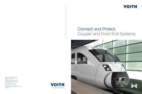
<strong>Connect</strong> <strong>and</strong> <strong>Protect</strong>.<br />
<strong>Coupler</strong> <strong>and</strong> <strong>Front</strong> <strong>End</strong> <strong>Systems</strong>
<strong>Voith</strong> <strong>Turbo</strong> Scharfenberg –<br />
Systematic Safety<br />
Quality <strong>and</strong> safety – these are the attributes associated with <strong>Voith</strong> <strong>Turbo</strong><br />
Scharfenberg for more than a century: In 1903, Karl Scharfenberg put<br />
his first vision of an automatic train coupler into practice.<br />
2<br />
1 Karl Scharfenberg.<br />
Continuous technical refinements <strong>and</strong> updated technology<br />
have made the “Schaku” one of the most prominent railway<br />
coupler systems all over the world. More than 500 000 couplers<br />
in use to date, from light rail vehicles to high speed trains,<br />
show the high degree of trust the customers have in Scharfenberg<br />
products.<br />
1<br />
Major Mile Stones on the Scharfenberg Track Record<br />
1903 Development of the first automatic Schaku<br />
by Karl Scharfenberg; German Reichspatent<br />
1921 Foundation of the incorporated company<br />
“Scharfenberg Aktiengesellschaft“ in Berlin<br />
1925 Introduction of the “Schaku” at the rapid<br />
transit railway “Berliner S-Bahn” <strong>and</strong> the<br />
“Hamburger Hochbahn”<br />
1957 The “Scharfenberg GmbH” becomes part of<br />
the Salzgitter group of companies<br />
1998 Foundation of the “<strong>Voith</strong> <strong>Turbo</strong><br />
Scharfenberg GmbH & Co. KG”<br />
2002 System supplier for complete train front ends,<br />
including complete front end systems; joints;<br />
system for automatically coupling AAR type<br />
couplers including electric head <strong>and</strong> air pipe<br />
connections. The type 10 Scharfenberg coupler<br />
is declared st<strong>and</strong>ard coupler for high speed trains<br />
2006 Modular coupler head One4; energy absorbing<br />
joints; modular adapter coupler<br />
2008 New data transmission concepts;<br />
start of the GFRP production on the Salzgitter site<br />
2010 Fibre composite vehicle head Galea as new energy<br />
absorption concept; CFRP adapter coupler;<br />
new crash buffers<br />
2012 Expansion of the Galea concept as test bed for<br />
innovative technologies<br />
Today, <strong>Voith</strong> <strong>Turbo</strong> Scharfenberg system solutions cover the<br />
whole range of energy absorbing components for train front<br />
ends, including kinematics <strong>and</strong> control electronics. Be it light<br />
rail, monorail or metro vehicles, regional transport or high<br />
speed trains, <strong>Voith</strong> <strong>Turbo</strong> Scharfenberg products are suited for<br />
any of your applications <strong>and</strong> perfectly adapted to their purpose.<br />
In best Scharfenberg tradition we are always one step<br />
ahead of our time – keeping our eyes firmly on the safety of<br />
passengers <strong>and</strong> train. One of the First Scharfenberg <strong>Coupler</strong>s Modular Concept of Modern Schakus<br />
Galea Concept Mainly Made from Fibre Composite Materials<br />
3
On our <strong>Systems</strong>, Safety always gets a<br />
free Ride. Energy absorbing Components<br />
from <strong>Front</strong> <strong>End</strong> <strong>Systems</strong> to Joints<br />
4<br />
Automatic <strong>Front</strong> <strong>Coupler</strong>s<br />
P. 6 Automatic <strong>Coupler</strong> Types<br />
P. 16 Modular Design<br />
P. 18 <strong>Coupler</strong> Head<br />
P. 20 Data Transmission Concepts<br />
P. 22 Energy Absorption (<strong>Coupler</strong> Shank)<br />
P. 24 Drawgear Articulation<br />
<strong>Front</strong> <strong>End</strong> <strong>Systems</strong><br />
P. 14 More Safety for Products<br />
of other Manufacturers<br />
P. 34 Galea Vehicle Head Concept<br />
P. 38 References <strong>Front</strong> <strong>End</strong><br />
<strong>Systems</strong> for High Speed Applications<br />
Intermediate <strong>Connect</strong>ions<br />
between Wagons<br />
P. 26 Semi-Permanent <strong>Coupler</strong>s<br />
P. 28 Joints<br />
P. 30 Buffers <strong>and</strong> Crash Solutions<br />
5
The type 10 Scharfenberg coupler excels in strength <strong>and</strong><br />
rigidity <strong>and</strong> possesses a particularly wide horizontal <strong>and</strong><br />
vertical gathering range. In 2002, it was declared st<strong>and</strong>ard<br />
coupler for high speed applications <strong>and</strong> is now an inherent<br />
part of the TSI (Technical Specification for Interoperability).<br />
This coupler can be found in nearly all state railways<br />
<strong>and</strong> a multitude of high speed trains world-wide, e.g. in<br />
Germany (ICE), France (TGV), Spain (AVE trains) or China<br />
(CRH series).<br />
6<br />
1 2 3 4<br />
1 High Speed DMU VLocity, Australia.<br />
2 Pesa Elf EMU, Pol<strong>and</strong>.<br />
3 Highspeed Train Velaro CN, China.<br />
4 Low-Floor Multiple Unit Train FLIRT, Europe.<br />
Power-Pack for St<strong>and</strong>ard Gauge <strong>and</strong><br />
High Speed Applications – Type 10<br />
Type 10 Characteristics<br />
• Strength:<br />
Compression: 1 500 kN (up to 2 000 kN)<br />
Tension: 1 000 kN<br />
• Compliant with the UIC st<strong>and</strong>ard for st<strong>and</strong>ard<br />
gauge motor train units<br />
• Two-position coupler lock<br />
Automatic Scharfenberg <strong>Coupler</strong><br />
Automatic Scharfenberg couplers are mainly found at the<br />
train ends. Allowing automatic <strong>and</strong> safe coupling / uncoupling,<br />
they permit a flexible train set configuration on the<br />
track. Different coupler types are available, depending on<br />
the application <strong>and</strong> required forces.<br />
Type 10 Automatic Scharfenberg <strong>Coupler</strong> Featuring Side-Mounted Electric Heads, Centring Device <strong>and</strong> Downstream Deformation Tube<br />
7
8<br />
1 2<br />
The Beast of Burden for Metro <strong>and</strong><br />
All-Electric Vehicles – Type 35<br />
The type 35 coupler is mainly used for metro vehicles <strong>and</strong><br />
it is also suitable for all-electric vehicles. It can be found e.g.<br />
in Shanghai, Singapore, Salt Lake City <strong>and</strong> Edmonton<br />
(Canada).<br />
Type 35 Characteristics<br />
• Strength:<br />
Compression: 1 300 kN<br />
Tension: 850 kN<br />
• Guiding horn for increased gathering range<br />
• Two-position coupler lock<br />
1 Nanjing Metro, China.<br />
2 Shanghai Metro Line 7, China.<br />
3 Mumbai Monorail, India.<br />
4 Delhi Metro, India.<br />
Type 35 Automatic Scharfenberg <strong>Coupler</strong> Featuring Electric<br />
Heads <strong>and</strong> Centring Device<br />
Versatile for Light Rail <strong>and</strong><br />
Monorail Vehicles – Type 330<br />
The type 330 is mainly found in light rail <strong>and</strong> monorail<br />
vehicles. Despite its small dimensions it offers remarkable<br />
strength <strong>and</strong> the possibility to use bottom-mounted electric<br />
heads. It features a wide gathering range, even without<br />
a guiding horn. Designed as foldable or retractable coupler,<br />
it can be hidden behind closed front hatches. The extremely<br />
narrow dimensions of the tramtrain Avanto in Paris even<br />
called for a coupler that folds twice along its longitudinal axis.<br />
Type 330 Characteristics<br />
• Strength:<br />
Compression: 800 kN<br />
Tension: 600 kN<br />
• Particularly wide gathering range without guiding horn<br />
3 4<br />
Type 330 Automatic Scharfenberg <strong>Coupler</strong> Featuring Bottom-<br />
Mounted Electric Head <strong>and</strong> Rubber Cushion Drawgear<br />
9
Light-Weight Design for Urban<br />
Railways – Type 430 <strong>and</strong> Type 530<br />
Its compact <strong>and</strong> lightweight design makes the types 430<br />
<strong>and</strong> 530 ideal couplers for low-floor urban railways, monorails<br />
<strong>and</strong> people movers. Designed as foldable couplers,<br />
they can be combined with front hatches. Type 430 couplers<br />
can be found in Berlin (Berliner Straßenbahn), Kuala<br />
Lumpur (KL Rapid) or the monorails of Sao Paulo <strong>and</strong> King<br />
Abdullah Financial District. The type 530 was mainly devel-<br />
oped for the Eastern German market <strong>and</strong> is compatible to<br />
the TGL couplers that used to be very common there.<br />
Type 430 / 530 Characteristics<br />
• Strength:<br />
Compression / tension: 300 kN<br />
• Small dimensions, low weight<br />
• Compact design without guiding horn<br />
10<br />
1<br />
2<br />
Type 430 Automatic Scharfenberg <strong>Coupler</strong> Featuring Integrated<br />
Electric Heads <strong>and</strong> Rubber Cushion Drawgear with Support<br />
1 São Paulo Monorail (Type 430 <strong>Coupler</strong> <strong>and</strong><br />
Energy Absorbing Anti-Climbers), Brazil.<br />
2 Halle Lightrail Vehicle (Type 530 <strong>Coupler</strong>), Germany.<br />
The Tough Ones –<br />
Type 55 <strong>and</strong> Type 140<br />
<strong>Coupler</strong>s for industrial applications need to be extremely<br />
robust <strong>and</strong> wear resistant, just like the type 55 <strong>and</strong> 140<br />
Scharfenberg couplers. Especially in shunting operations or<br />
automated marshalling of trains, these couplers make the<br />
industrial working environment considerably safer.<br />
For Shunting <strong>and</strong> Unimog <strong>Coupler</strong>s – Type 55<br />
This coupler – developed in compliance with the UIC directive<br />
for drawhooks – provides safety <strong>and</strong> rationalisation in<br />
shunting operations. Coupling <strong>and</strong> uncoupling can be effected<br />
automatically <strong>and</strong> no longer require any shunting<br />
staff. The type 55 coupler allows automatic coupling with a<br />
drawhook.<br />
The robust <strong>and</strong> service friendly coupler significantly re-<br />
duces wear <strong>and</strong> maintenance – perfect for rough operating<br />
conditions.<br />
Type 55 Automatic Scharfenberg <strong>Coupler</strong><br />
For Freight Wagons <strong>and</strong> Industrial Railways – Type 140<br />
This coupler type was designed for heavy duty loads under<br />
rough environmental conditions. Typical applications are<br />
coal <strong>and</strong> ore transport, pig iron transport, mould cars <strong>and</strong><br />
steel pouring ladle cars.<br />
In order to endure the extreme operating conditions,<br />
this type features an extremely robust coupler head which<br />
offers very good strength characteristics (compression up to<br />
2 500 kN, tension up to 1 500 kN).<br />
Type 140 Automatic Scharfenberg <strong>Coupler</strong><br />
11
For Shunting or Towing.<br />
Adapter <strong>Coupler</strong>s<br />
Adapter couplers are used whenever different coupler types need to<br />
be connected or the coupling height is not compatible. During st<strong>and</strong>ard<br />
train operation this should not occur, but it is common practice in<br />
shunting or towing operations.<br />
Modular Adapter <strong>Coupler</strong><br />
Traditional adapter couplers were mostly very special in design<br />
<strong>and</strong> layout, as they had to be adapted to one particular<br />
combination of coupler heads as well as a particular difference<br />
in coupling height.<br />
This new modular approach separates the individual parts,<br />
namely the two coupler heads <strong>and</strong> the intermediate adapter<br />
piece bridging the offset in height. Should no adapter piece<br />
be required, the coupler heads can just as well be directly<br />
connected. This way, adapter couplers of any combination<br />
can be individually <strong>and</strong> flexibly assembled.<br />
What is more, the individual components are mounted on<br />
the train one after the other, so that only a fraction of the<br />
weight needs to be carried at a time.<br />
Modular Adapter <strong>Coupler</strong> with <strong>and</strong> without Intermediate Adapter<br />
Piece, Sample Configuration<br />
12<br />
CFRP Adapter: High-Tech Towing<br />
Adapter couplers are only needed for towing or shunting trains.<br />
This means, they need to be fitted by the operating staff on<br />
track – manually, of course. An ideal adapter coupler would be<br />
lightweight <strong>and</strong> yet able to bear the heavy load of a whole train.<br />
For common steel couplers used to date, the possibilities<br />
for weight reduction are virtually exhausted. This new type<br />
of adapter coupler mainly consists of carbon fibre reinforced<br />
plastics, a hightech material often to be found in aviation technology.<br />
Its weight of only 23 kg allows the coupler to be fitted<br />
on the train by one person alone.<br />
CFRP Adapter <strong>Coupler</strong><br />
Looking Beyond Our Own Horizon.<br />
<strong>Coupler</strong>s of Other Makes<br />
More than 100 years of experience have made us experts in couplers,<br />
including those of other makes. We offer efficient solutions for connections<br />
<strong>and</strong> energy absorption systems of all kinds.<br />
AAR Type <strong>Coupler</strong><br />
AAR type couplers are in common use on railcars on the<br />
American market <strong>and</strong> suited for heavy loads. The mechanical<br />
connection between the couplers is established automatically,<br />
whereas the large coupler head play usually does<br />
not allow any pneumatic or electric connection. These, however,<br />
can be integrated into an additional support system.<br />
For further information, refer to page 14.<br />
AAR <strong>Coupler</strong><br />
Wedgelock Type <strong>Coupler</strong><br />
The Wedgelock principle can be mainly found on British<br />
trains <strong>and</strong> also allows automatic coupling. Here, the coupler<br />
lock members are held in place by pneumatically operated<br />
wedges.<br />
Wedgelock <strong>Coupler</strong><br />
Tomlinson Type <strong>Coupler</strong><br />
Tomlinson couplers are also mainly used on the American<br />
market. <strong>Voith</strong> <strong>Turbo</strong> Scharfenberg has developed a prototype<br />
combining their proven energy absorption systems<br />
with the Tomlinson coupling principle, allowing mechanical,<br />
electric <strong>and</strong> pneumatic connections to be established automatically.<br />
Tomlinson <strong>Coupler</strong><br />
GF (Fischer) Type <strong>Coupler</strong><br />
The GF type automatic coupler is widespread in Belgium<br />
<strong>and</strong> Switzerl<strong>and</strong>. During automatic coupling, the cone <strong>and</strong><br />
funnel shaped coupler heads interlock. The couplers can be<br />
provided with air pipe connections <strong>and</strong> electric heads.<br />
GF Type <strong>Coupler</strong><br />
13
More Safety for Products<br />
of Other Manufacturers<br />
Example: Crash Energy Management for AAR <strong>Coupler</strong>s. So far US-<br />
American train manufacturers <strong>and</strong> operators have mainly focused on<br />
massive <strong>and</strong> rigid carbodies. Some serious train accidents during the<br />
last years, however, have caused a mind-shift towards an introduction<br />
of crash energy management systems to increase passenger safety.<br />
In California, the acquisition of a new vehicle-fleet for SCRRA Metrolink<br />
was postponed until a solution would be found to efficiently protect<br />
both passengers <strong>and</strong> trains. The vehicles were equipped with Crash<br />
Energy Management (CEM) using <strong>Voith</strong> <strong>Turbo</strong> Scharfenberg techno-<br />
logy. Today, a complete CEM system is available, complying with<br />
the latest FRA safety regulations.<br />
CEM System<br />
A Crash Energy Management system is composed of several<br />
matched energy absorbing components which are integrated<br />
in both the coupler <strong>and</strong> the carbody. The energy absorp-<br />
tion works in a cascading way, compensating a high amount<br />
of energy in case of a crash <strong>and</strong> preventing an overriding of<br />
the cars.<br />
Constituent Parts of the System:<br />
• “Push back” AAR coupler including support<br />
• Anti-climber<br />
• Lateral energy absorbers<br />
CEM System (SMART Project) Push Back <strong>Coupler</strong><br />
Anti-Climber<br />
Lateral Energy Absorber<br />
14<br />
1 SCRRA Metrolink Vehicle, California,<br />
Featuring Push Back <strong>Coupler</strong> <strong>and</strong> Lateral<br />
Energy Absorbers.<br />
Working Principle: 1. Step – <strong>Coupler</strong><br />
A st<strong>and</strong>ard AAR coupler head was fitted with state-of-the-art<br />
energy absorption features, forming a “push back” coupler.<br />
The drawgear is mounting compatible to that of st<strong>and</strong>ard AAR<br />
couplers. In addition to the usual reversible energy absorption<br />
element it contains an irreversible part based on deformation<br />
tube technology. Should a crash occur, the coupler is pushed<br />
back into the drawgear, absorbing a great amount of energy<br />
on its way.<br />
1<br />
2. Step – Anti-Climber<br />
At a certain point during the push-back process, the anti-<br />
climber brackets interlock <strong>and</strong> thus prevent any vertical movement<br />
of the cars.<br />
A separate support structure mounted sideways of the coupler<br />
ensures that the energy absorption takes place in a con-<br />
trolled manner. One part of this support carries the anti-climber,<br />
another supports the coupler, the latter pivoting out of the way<br />
as soon as the push-back process starts.<br />
3. Step – Lateral Energy Absorbers<br />
Two lateral energy absorbers have been integrated into the<br />
carbody structure above the coupler level. At their front ends,<br />
they are connected through the anti-climber. This way, additional<br />
energy will be absorbed as the crash proceeds.<br />
15
Modularity: Everthing’s Possible<br />
Apart from reliability <strong>and</strong> safety aspects, flexibility <strong>and</strong> adaptability are<br />
the main requirements a train coupler has to comply with. The modular<br />
design of the Scharfenberg couplers <strong>and</strong> different coupler types allow<br />
us to provide the optimum coupler for each <strong>and</strong> every application<br />
<strong>and</strong> condition.<br />
16<br />
P. 20 Data <strong>and</strong> Signal Transmission<br />
P. 18 <strong>Coupler</strong> Head<br />
P. 22 <strong>Coupler</strong> Shank /<br />
Energy Absorption <strong>Systems</strong> P. 24 Drawgear Articulation<br />
17
<strong>Coupler</strong> Head –<br />
the <strong>Coupler</strong>’s Centrepiece<br />
An automatic coupler’s key functionalities are resumed by<br />
the coupler head. The connection of two couplers – mechanically,<br />
pneumatically <strong>and</strong> electrically as required – can only be established<br />
through the coupler head <strong>and</strong> its locking mechanism.<br />
The Special Design<br />
The cone <strong>and</strong> funnel shape of the coupler face establishes<br />
a rigid <strong>and</strong> slack-free connection, reducing coupler play to a<br />
minimum. <strong>Coupler</strong> head extensions <strong>and</strong> a guiding horn assure<br />
the maximum possible gathering range. This way, automatic<br />
coupling is possible even under horizontal, vertical or angular<br />
offset, as for example in curves or on hilltops.<br />
<strong>Coupler</strong> Lock Components (Two-Position <strong>Coupler</strong> Lock)<br />
18<br />
Coupling Link Hooked Plate<br />
Tension Spring<br />
<strong>Coupler</strong> Lock: Safe <strong>and</strong> Wear-Resistant<br />
The coupler lock is the functional heart of every automatic<br />
Schaku. It mainly consists of a pivot-mounted hooked plate,<br />
a coupling link <strong>and</strong> tension springs. During coupling, the coupling<br />
links <strong>and</strong> hooked plates of the two couplers interlock,<br />
forming an equilibrium of forces. A very simple, but efficient<br />
mechanism that excels in wear-resistance <strong>and</strong> safety, even under<br />
extreme conditions.<br />
Central Pivot<br />
Locking Device<br />
(only for two-position coupler locks)<br />
Modularity at Peak Level – One4<br />
The One4 coupler head concept is a logical consequence of our modular<br />
way of thinking. <strong>Coupler</strong> head <strong>and</strong> coupler body were separated,<br />
the coupler body designed as a “one size fits it all” piece to be fitted<br />
with the individual, type specific front plate. This can be easily replaced<br />
<strong>and</strong> yet remains compatible to existing couplers.<br />
Enjoy Maintenance<br />
The One4 offers a number of benefits, especially for repair<br />
<strong>and</strong> maintenance. When the coupler front plate is removed,<br />
the coupler lock components are easily accessible <strong>and</strong> can be<br />
replaced without any special tools.<br />
One4 <strong>Coupler</strong> Head: Completely Modular Concept with Removable<br />
<strong>Front</strong> Plate <strong>and</strong> St<strong>and</strong>ardised Electric Head Operating Gear<br />
One4 with Removed <strong>Front</strong> Plate<br />
Furthermore, a st<strong>and</strong>ardised electric head operating gear <strong>and</strong><br />
heating concept considerably save repair time <strong>and</strong> effort.<br />
St<strong>and</strong>ardised Electric Head Operating Gear Support (for Lateral<br />
Electric Heads)<br />
Heating Elements<br />
19
Electric Heads <strong>and</strong> <strong>Coupler</strong> /<br />
<strong>Front</strong> Hatch Control Units<br />
Apart from power transmission, electric heads are used for transmitting<br />
control signals as well as data <strong>and</strong> video signals. They are mounted<br />
on the coupler head <strong>and</strong>, when uncoupled, are protected from the<br />
ingress of dirt <strong>and</strong> water by means of electric head covers. Our microprocessor<br />
based coupler <strong>and</strong> front hatch control units offer st<strong>and</strong>ard<br />
plug-<strong>and</strong>-play interfaces for controlling <strong>and</strong> diagnosing the interaction<br />
of automatic couplers <strong>and</strong> front hatch systems.<br />
Electric Head Casing Models<br />
St<strong>and</strong>ardised electric head casing models <strong>and</strong> interfaces en-<br />
sure easy installation <strong>and</strong> a perfect interaction of all components.<br />
Depending on the number of contacts required <strong>and</strong> on the<br />
position of the electric head with relation to the mechanical<br />
head, different casing types are available: two for lateral arrangement,<br />
<strong>and</strong> one for top or bottom mounted electric heads.<br />
A st<strong>and</strong>ard electric head includes a contact block fitted with<br />
contacts, cables <strong>and</strong> a h<strong>and</strong> plug. The contacts are easily replaceable<br />
from the front, the h<strong>and</strong> plug ensures an easy-to-fit<br />
connection to the carbody.<br />
20<br />
<strong>Coupler</strong> <strong>and</strong> <strong>Front</strong> Hatch Control<br />
Perfect interaction is also required for coordinated coupler <strong>and</strong><br />
front hatch movements. Our control unit operates all actuators<br />
of this system <strong>and</strong> provides an easy-to-use control <strong>and</strong> diagnosis<br />
interface to the vehicle. Diagnosis comprises only few<br />
signals, keeping the cabling manageable <strong>and</strong> still considerably<br />
reducing requirements for diagnosis on the vehicle side.<br />
The robust coupler <strong>and</strong> front hatch control unit can be mounted<br />
either on the car underframe or in the front nose.<br />
A data bus connection to the vehicle is optional, <strong>and</strong> both service<br />
<strong>and</strong> maintenance software are available for maintenance<br />
purposes.<br />
The Three St<strong>and</strong>ard Electric Head Casing Models <strong>Coupler</strong> <strong>and</strong> <strong>Front</strong> Hatch Control Unit, Cover Removed<br />
Performance Enhancement<br />
Made Easy<br />
So far performance enhancements for signal <strong>and</strong> data transmission<br />
through the coupler meant considerable effort <strong>and</strong> high expenses,<br />
particularly for retrofit solutions. <strong>Voith</strong> <strong>Turbo</strong> Scharfenberg has deve-<br />
loped Fast Ethernet based systems for different applications, covering<br />
both new vehicles <strong>and</strong> upgrades of trains already in operation.<br />
Without Electric Head: RadiConn<br />
RadiConn is a contact-free data transmission concept which<br />
is particularly resistant to soiling, keeping the failure rate – <strong>and</strong><br />
related maintenance works – at a minimum. The system uses<br />
near-field radio coupler pins. These may be integrated into the<br />
electric head, but can just als well be mounted anywhere on<br />
the mechanical coupler head. This makes the RadiConn particularly<br />
interesting for retrofit applications.<br />
For New Vehicles: QuatConn<br />
QuatConn is a solution comprising 4-pole pin <strong>and</strong> socket connectors<br />
which need to be integrated into an electric head.<br />
Once a contact block has been prepared to hold the contacts,<br />
these are mounted just like the st<strong>and</strong>ard ones. This makes the<br />
QuatConn a preferred solution for new vehicles.<br />
RadiConn <strong>Coupler</strong> Pins<br />
Cost-Effective Retrofit Solution: TLM<br />
The Train Line Modem (TLM) shares the contacts <strong>and</strong> lines of<br />
an already configured electric head using a special modulation<br />
technique. This way, control <strong>and</strong> operating signals as well<br />
as train information, video or CCTV data may be transmitted<br />
without any modification on the coupler. A cost-effective solution<br />
for trains already in operation.<br />
Gigabit <strong>Connect</strong>or: OctiConn<br />
The OctiConn connectors work along the line of the<br />
QuatConn, but they offer a higher data transmission rate of<br />
1 Gigabit/second.<br />
OctiConn<br />
21
Energy Absorption for More Safety –<br />
<strong>Coupler</strong> Shank<br />
The coupler shank plays a major role in train safety. Customised to fit<br />
its individual purpose <strong>and</strong> application, it integrates the coupler’s energy<br />
absorption features. Reversible energy absorbing components like<br />
dampers smoothen train operation <strong>and</strong> compensate minor impacts.<br />
Irreversible (destructive) energy absorbing components like deformation<br />
tubes, on the other h<strong>and</strong>, can cope with major impacts. All energy absorbing<br />
features in a train set are meticulously matched in a cascading<br />
way to ensure a most efficient interaction.<br />
Deformation Tube<br />
The deformation tube converts impact load into deformation.<br />
Its energy absorption characteristics allow the deformation<br />
tube to compensate major impacts. However, it will be destroyed<br />
while doing so.<br />
Characteristics<br />
• Defined release load without peak value<br />
• Force stroke curve can be adapted to requirements<br />
• Max. energy absorption (when designed for rectangular<br />
Deformation Tube (<strong>Coupler</strong> Shank)<br />
22<br />
response curve)<br />
Downstream Deformation Tube<br />
This version of a deformation tube is not part of the coupler<br />
shank, but mounted on the rear end of a bearing bracket with<br />
shear-off feature, i.e. behind the coupler’s mounting plate.<br />
Any impact exceeding the absorption capacity of the coupler<br />
will result in a shearing-off, pushing the coupler rearwards<br />
through the deformation tube at a constant force level.<br />
Rear <strong>End</strong> of <strong>Coupler</strong> Featuring Downstream Deformation Tube<br />
Gas-Hydraulic Damper<br />
In combination with a friction spring, the gas-hydraulic damper<br />
converts both compressive <strong>and</strong> tensile load in a regenerative<br />
way. They can be designed such that they function as “regenerative<br />
deformation tubes”: In case of excessive load an internal<br />
bypass will be opened at a defined load level.<br />
Characteristics<br />
• Speed-related response curve<br />
• Pre-loaded system in both directions,<br />
tension <strong>and</strong> compression<br />
• Usually combined with spherical bearing<br />
Gas-Hydraulic Damper<br />
Hydrostatic Damper<br />
The hydrostatic damper converts compressive load in a<br />
regenerative way.<br />
Characteristics<br />
• Straight proportional response curve<br />
• Pre-loaded system in direction of compression<br />
• Usually combined with rubber cushion drawgear<br />
Hydrostatic Damper<br />
23
Working Mode of the Rubber Cusion Drawgear: Neutral Position<br />
<strong>Coupler</strong> Meets Carbody –<br />
Drawgear Articulation<br />
The drawgear articulation establishes the connection to the carbody.<br />
Elastic components allow cardanic coupler moves <strong>and</strong> cushion minor<br />
impacts. Depending on its purpose <strong>and</strong> application, the drawgear articulation<br />
can be fitted with additional energy absorbing components to<br />
compensate tensile <strong>and</strong> compressive loads.<br />
Rubber Cushion Drawgear with <strong>and</strong> without<br />
Shear-off Feature<br />
The rubber cushion drawgear is a bearing bracket with integrated<br />
cushioning unit. Comprising either two or three rubber<br />
elements, the rubber cushion drawgear compensates both<br />
tensile <strong>and</strong> compressive loads <strong>and</strong> can be individually adapted<br />
to its purpose.<br />
Additionally, it can feature a shear-off solution. If the maximum<br />
load is exceeded, the screws fixing the cushioning unit shear<br />
off, <strong>and</strong> the whole coupler pushes rearwards under the carbody<br />
in a controlled way.<br />
24<br />
Rubber Cusion Drawgear under Compressive Load<br />
Rubber Cushion Drawgear with Shear-off Feature<br />
under Excessive Load<br />
3<br />
Rubber Cushion Drawgear under Tensile Load<br />
Bearing Bracket<br />
The bearing bracket represents the most straight-forward type<br />
of drawgear articulation: It is combined with a coupler shank<br />
featuring a spherical bearing to allow cardanic coupler moves.<br />
Just like the rubber cushion drawgear, the bearing bracket can<br />
feature an internal shear-off solution as overload protection.<br />
If further energy absorption is required, the bearing bracket can<br />
be fitted with a rear-mounted (downstream) deformation tube<br />
with defined response characteristics. Any impact exceeding<br />
the absorption capacity of the coupler will result in a shearingoff,<br />
pushing the coupler rearwards through the deformation<br />
tube at a constant force level.<br />
Bearing Bracket with Downstream Deformation Tube, Centring<br />
Device <strong>and</strong> Support<br />
Benefits:<br />
• High cushioning effect through shear stress of<br />
the rubber elements<br />
• Low-wear <strong>and</strong> maintenance-friendly design<br />
• Small dimensions<br />
• Different sizes for various applications<br />
Rubber Ring / Rubber Cushion Articulation<br />
The rubber ring articulation is best suited for a narrow train<br />
front offering only small mounting dimensions. Being located<br />
on both sides – in front of <strong>and</strong> behind – the coupler mounting<br />
plate, the rubber rings cushion impacts in the direction of both<br />
compression <strong>and</strong> tension. They possess a softly rising force<br />
stroke curve <strong>and</strong> thus increase travelling comfort.<br />
Based on the rubber ring principle, the rubber cushion articulation<br />
features rectangular rubber elements. They function as<br />
anti-rotation device, while at the same time allowing a high degree<br />
of cardanic moves.<br />
These drawgear articulations can also be designed as overload<br />
protection solutions.<br />
Rubber Cushion Articulation<br />
25
Semi-Permanent <strong>Coupler</strong>s<br />
Semi-permanent couplers establish a safe <strong>and</strong> reliable permanent<br />
connection between intermediate cars. Usually, the two<br />
coupler halves are connected by means of muff couplings, allowing<br />
them to be easily separated, should this be necessary.<br />
The energy absorption characteristics of the semi-permanent<br />
couplers are matched with those of the automatic couplers.<br />
This distribution of forces over the whole train allows for a lean<br />
underframe design. Result: maximum safety at reduced costs.<br />
Semi-Permanent <strong>Coupler</strong> with Air Pipe <strong>Connect</strong>ions, Electric<br />
Head, Energy Absorbing Components <strong>and</strong> Gangway Support<br />
26<br />
Semi-Permanent <strong>Coupler</strong> with Anti-Climbing Feature<br />
For the first time, a semi-permanent coupler for metro<br />
vehicles assumes anti-climbing function. Contrary to conventional<br />
systems, this coupler has a stabilising effect even before<br />
any overriding occurs. The dimensions of the coupler remain<br />
unaffected by this new technology.<br />
Semi-Permanent <strong>Coupler</strong> with Anti-Climbing Feature<br />
Anti-Climbing Feature: Working Principle<br />
During a train crash or heavy impact, the longitudinal forces<br />
are converted into vertical swerving movements leading to<br />
an overriding of the cars once a critical momentum has been<br />
exceeded. This may cause the wagon to disconnect from its<br />
Jacobs bogie <strong>and</strong> damage softer structures.<br />
The anti-climbing feature has been designed to prevent this<br />
overriding right from the start. To do so, it uses a simple, yet<br />
highly efficient principle: The rear end of the coupler shank features<br />
a special geometry. As soon as the reversible stroke of<br />
the coupler has been utilised, this geometry interlocks with the<br />
bearing bracket, building a counter-momentum that holds the<br />
wagons down.<br />
Additional energy absorbing components of the semi-permanent<br />
coupler, e.g. deformation tubes or hydrostatic dampers,<br />
convert kinetic energy <strong>and</strong> help to keep the load on a controllable<br />
level.<br />
Semi-Permanent <strong>Coupler</strong> with Anti-Climbing Feature: Working Principle<br />
F<br />
crash<br />
solid contact<br />
F<br />
crash<br />
Stabiliy <strong>and</strong> Safety in Between: Semi-permanent<br />
<strong>Coupler</strong>s <strong>and</strong> Joints<br />
Optimum safety requires a perfect interaction of all the<br />
connecting components in a trainset. In case of an impact,<br />
the automatic couplers <strong>and</strong> further energy absorbing components<br />
of the train front end work h<strong>and</strong> in h<strong>and</strong> with the<br />
semi-permanent couplers <strong>and</strong> joints connecting the wagons.<br />
Operating in a cascading way, they function as one<br />
matched system, absorbing the highest possible impact<br />
energy <strong>and</strong> preventing an overriding of the cars. The semipermanent<br />
coupler with anti-climbing feature has been<br />
especially designed for this purpose.<br />
solid contact<br />
F<br />
crash<br />
27
Joints<br />
Whenever trains are equipped with Jacobs bogies, joints are<br />
used as intermediate connections between the cars. They<br />
transmit driving forces between the car bodies, harmonise<br />
deflection angles <strong>and</strong> cushion impacts. Joints always have a<br />
connection with the Jacobs bogie, entraining it during train<br />
operation.<br />
Joint Fork <strong>and</strong> Joint Eye<br />
28<br />
Deformation Tube<br />
Basic Design<br />
Basically, joints consist of two parts which are connected: joint<br />
fork <strong>and</strong> joint eye with spherical bearing. The spherical bearing<br />
allows cardanic movements <strong>and</strong> cushions impacts.<br />
Contrary to semi-permanent couplers, joints also compensate<br />
vertical loads. A torsion bar suspension mounted between the<br />
cars brings additional stability.<br />
1<br />
Energy Absorbing Joints<br />
Should additional energy absorption be needed (e.g. for<br />
heavy rail applications), joints may be fitted with energy absorbing<br />
elements. Our st<strong>and</strong>ard energy absorbing joint can<br />
be provided with deformation tubes on both ends – a proven<br />
technology which can be exactly matched with your re-<br />
quirements. A combination of both energy absorbing joints<br />
<strong>and</strong> non energy absorbing joints is also possible.<br />
Energy Absorbing Joint with Deformation Tube in Sectional View (One Side)<br />
29
Buffer for Passenger<br />
Trains <strong>and</strong> Freight Wagons<br />
In co-operation with SMW Spezialmaschinen, <strong>Voith</strong> <strong>Turbo</strong> Scharfenberg<br />
has developed two types of ready-to-use crash buffers: VSSM-105-400<br />
for freight <strong>and</strong> tank wagons as well as locomotives <strong>and</strong> VSSM-110-170<br />
for passenger trains. The buffers are TSI conform <strong>and</strong> meet all safety<br />
requirements. This means additional safety <strong>and</strong> comfort without any<br />
adaptations. Their compact design <strong>and</strong> st<strong>and</strong>ardised interfaces allow<br />
the buffers to be replaced very quickly <strong>and</strong> also make them suitable for<br />
retrofit applications.<br />
More Safety for Freight Wagons<br />
This crash buffer has a reversible stroke of 105 mm <strong>and</strong> an<br />
energy absorption of minimum 400 kJ. A combination of a<br />
spring <strong>and</strong> an energy absorption element, these TSI conform<br />
buffers meet all the requirements according to UIC 573 (crashworthiness),<br />
DIN EN 15551 <strong>and</strong> UIC 526 (cat. A). They offer<br />
increased impact protection <strong>and</strong> safety, even for the transport<br />
of hazardous goods. In case of an impact, there will be no<br />
intrusion into the vehicle underframe.<br />
VSSM-105-400 for Freight Wagons<br />
30<br />
Comfort <strong>and</strong> Safety for Passenger Trains<br />
This crash buffer also combines reversible <strong>and</strong> irreversible<br />
energy absorption. In compliance with the technical specification<br />
for the interoperability of locomotives <strong>and</strong> passenger<br />
rolling stock (TSI CR LOC+PAS) it features a reversible stroke<br />
of 100 mm <strong>and</strong> an energy absorption of minimum 170 kJ.<br />
Down to -40 °C it meets the highest dem<strong>and</strong>s concerning<br />
safety <strong>and</strong> travelling comfort. In combination with SA3 couplers,<br />
the two-stage spring concept even allows cross-border<br />
operations.<br />
VSSM-110-170 for Passenger Trains<br />
Crash Elements <strong>and</strong> Crash Boxes<br />
Should further energy absorption be required, <strong>Voith</strong> <strong>Turbo</strong> Scharfenberg<br />
provides tailor-made solutions. These can be specifically designed<br />
according to their application <strong>and</strong> requirement profile <strong>and</strong> thus offer<br />
the best possible protection for both passengers <strong>and</strong> train.<br />
Crash Elements for UIC Side Buffers<br />
Crash elements for locomotives are mounted between the<br />
lateral UIC buffers <strong>and</strong> the locomotive car body. They are<br />
equipped with proven <strong>and</strong> tested deformation tubes. Their<br />
st<strong>and</strong>ard UIC flange allows all kinds of side buffers to be connected.<br />
In case of a crash, the UIC flanges can completely<br />
slide into the deformation tubes.<br />
1 Crash Elements for UIC Side Buffers.<br />
1<br />
Crash Boxes<br />
The collapsible crash boxes are made of steel plate <strong>and</strong> situated<br />
in the train front end behind the coupler level. In case of a<br />
crash exceeding the coupler’s energy absorption capacity, the<br />
remaining energy is transferred to the crash boxes <strong>and</strong> converted<br />
into deformation energy. Lateral anti-climbers provide<br />
additional safety.<br />
Crash Boxes Mounted on a Cross Beam Behind the <strong>Coupler</strong><br />
31
<strong>Front</strong> <strong>End</strong> <strong>Systems</strong><br />
Modular, safe, functional –<br />
our st<strong>and</strong>ard for front end systems<br />
32<br />
33
<strong>Connect</strong> <strong>and</strong> <strong>Protect</strong> – Galea<br />
<strong>Front</strong> end design is caught in a crossfire of influences: safety aspects,<br />
economic <strong>and</strong> environmentally friendly operation, efficient maintenance<br />
<strong>and</strong> repair works. Using innovative GFRP technology, <strong>Voith</strong> <strong>Turbo</strong><br />
Scharfenberg combines structural elements <strong>and</strong> energy absorbing<br />
components to form a complete, modular vehicle head, teaming longst<strong>and</strong>ing<br />
experience with state-of-the-art technologies. Safe, flexible,<br />
lightweight <strong>and</strong> modular: The Galea concept represents a st<strong>and</strong>ardised<br />
“framework” for all types of exteriour designs. A perfect combination of<br />
individual appearance <strong>and</strong> optimum energy absorption.<br />
Safe<br />
Safety plays a major role in rail traffic, with ever increasing<br />
importance. To meet these high dem<strong>and</strong>s, the Galea inte-<br />
grates a multiple-stage crash concept. It was designed to<br />
cover the main aspects of the EN 15227 st<strong>and</strong>ard, when integrated<br />
into a trainset. Crashworthiness <strong>and</strong> fire protection, as well<br />
as noise protection <strong>and</strong> thermal insulation were taken into account.<br />
What st<strong>and</strong>s out: Even the crash elements are made<br />
from GFRP. The Galea was developed for Intercity trains up<br />
to 200 km / h.<br />
34<br />
Modular<br />
Just like every other Scharfenberg product, the Galea has<br />
been designed in a modular way. The entire vehicle head<br />
is characterised by short mounting times, <strong>and</strong> – when damaged<br />
– can be easily replaced. The same applies to the individual<br />
energy absorbing components. This way, train down times<br />
are minimised. The entire vehicle head will be delivered ready<br />
for installation. Apart from pre-installed pneumatic <strong>and</strong> electric<br />
components, it contains the interior panelling <strong>and</strong> driver’s desk<br />
(according to European drivers desk specifications).<br />
Lightweight<br />
The heavy-weight steel constructions in operation to date<br />
were replaced by lightweight structures using fibre composite<br />
materials. The weight reduction results in a higher economic<br />
efficiency <strong>and</strong> environmental acceptability. The load on every<br />
wheel is minimised, thus reducing the wear of train <strong>and</strong> tracks<br />
or respectively allowing an increased passenger volume.<br />
GFRP Energy Absorber Galea Vehicle Head<br />
Lightweight Design Using Fibre Composite Materials<br />
Additional Benefit<br />
The modular design allows the individual components of the<br />
energy absorption concept to be used as st<strong>and</strong>-alone solutions.<br />
This way, the new GFRP technology is open for other<br />
applications.<br />
Flexible<br />
The base of the Galea concept is its internal crash structure.<br />
This structure can be adapted to different vehicle heights<br />
<strong>and</strong> widths, but the design <strong>and</strong> the components making it<br />
up remain the same.<br />
For the external shell covering this crash structure any design<br />
can be realised. The result: individual design paired<br />
with optimum safety.<br />
Flexibly Adaptable Crash Structure<br />
35
Fibre Composite Vehicle Head Galea Consisting Almost Completely of Glass-Fibre Reinforced Plastics (GFRP)<br />
* Vehicle components made from GFRP<br />
Shell*<br />
36<br />
Laminated Safety Glass<br />
Energy Absorbers*<br />
Obstacle Deflector<br />
Scharfenberg <strong>Coupler</strong><br />
A-Pillars*<br />
Aluminium Honeycomb<br />
Structure<br />
<strong>Front</strong> Plate*<br />
Floor Plate*<br />
Crash concept in detail<br />
In addition to the reversible <strong>and</strong> irreversible energy absorption<br />
components of the coupler (EN 15227 crash scenario 1),<br />
side-mounted GFRP crash elements were integrated into the<br />
vehicle head structure. These are also provided with an efficient<br />
anti-climbing feature.<br />
Energy absorbing components within the floor structure are<br />
complemented by crash components at the front side of the<br />
A-pillars (EN 15227 crash scenario 3).<br />
The GFRP shell of the Galea has been designed such that –<br />
should a crash occur – all window panes are securely supported,<br />
protecting the driver.<br />
The combination of coupler, additional energy absorbing components<br />
<strong>and</strong> A-pillars together with a subtle choice of materials<br />
make sure that in case of a crash the driver’s survival space will<br />
be safeguarded.<br />
Points of reference<br />
• Fuel savings of 4848 litres diesel / year*<br />
• CO 2 emission reduced by 12 800 kg / year*<br />
* based on the following reference vehicle: three-car trainset<br />
(DMU / EMU); total weight: 180 t; energy absorbing components<br />
between the cars; kilometric performance: 200 000 km / year;<br />
weight reduction: approx. 1 000 kg per vehicle head.<br />
37
Play it Safe – even at Highspeed<br />
An ideal combination of functionality <strong>and</strong> safety: <strong>Voith</strong><br />
<strong>Turbo</strong> Scharfenberg front end systems offer perfectly<br />
matched components, individually designed for their<br />
operational purpose. St<strong>and</strong>ardised interfaces <strong>and</strong> a<br />
modular design make the systems easy to replace in case<br />
of damage <strong>and</strong> keep the down times of the train as short<br />
as possible.<br />
ICx<br />
Superlatives in rapid succession: From 2016 on, up to 300 ICx<br />
trains will gradually replace the Intercity/Eurocity trains presently<br />
in operation, followed by the ICE1 <strong>and</strong> ICE2 trains. Thus<br />
the ICx forms the new backbone of the future DB (German<br />
Railways) main line traffic. The ICx sets new st<strong>and</strong>ards in flexibility<br />
<strong>and</strong> operational availability <strong>and</strong> can be perfectly adapted<br />
to different transport tasks.<br />
An advanced aerodynamic design <strong>and</strong> optimised usable floor<br />
space result in weight <strong>and</strong> energy savings, while still providing<br />
all the comfort needed for long distance travels.<br />
1 ICx, Germany.<br />
38<br />
The modular design <strong>and</strong> few connection points of the front<br />
nose allow for fast mounting <strong>and</strong> easy adjustment of the components.<br />
Low-maintenance encapsulated actuators remain<br />
perfectly functional even under rough operating conditions.<br />
Apart from smooth operation, these actuators prevent any unwanted<br />
closing of the front hatches. This provides additional<br />
safety for maintenance works.<br />
Our Contribution<br />
• GFRP driver’s cabin<br />
• <strong>Front</strong> nose module including front hatches<br />
• <strong>Front</strong> hatch kinematics (manual <strong>and</strong> automatic)<br />
• Snow deflector<br />
• Type 10 automatic coupler<br />
• Semi-permanent couplers<br />
• Adapter coupler type 10 / UIC drawhook<br />
Zefiro 380<br />
An operating speed of 380 km / h makes this Chinese high<br />
speed train one of the world’s fastest commercially operated<br />
trains. It will play a key role on China’s growing high speed railway<br />
network. Apart from strength characteristics <strong>and</strong> safety,<br />
a main focus was set on energy efficient operation.<br />
A close co-operation with the vehicle manufacturer right from<br />
the beginning of the design process allowed the components<br />
to be perfectly matched.<br />
2 CRH1-380 (Zefiro), China.<br />
1 2<br />
Comprehensively adapted to European conditions, the Zefiro<br />
platform is also used for Italy’s new high speed train. With an<br />
operating speed of 360 km / h, it will be one of the fastest trains<br />
in Europe. Designed to cover several supply voltages, a crossborder<br />
operation is possible.<br />
Our Contribution<br />
• <strong>Front</strong> nose module including front hatches<br />
• <strong>Front</strong> hatch kinematics (automatic)<br />
• Type 10 automatic coupler<br />
• Semi-permanent couplers<br />
• Modular adapter coupler type 10 / AAR<br />
Components Supplied by <strong>Voith</strong> Components Supplied by <strong>Voith</strong><br />
39
CRH3-380<br />
Meanwhile, a whole family of CRH3 products has seen the light<br />
of day at the Salzgitter production site. They all have one thing<br />
in common: a huge delivery volume.<br />
Both the design process of the CRH3-380 front nose <strong>and</strong><br />
the manufacturing of the first systems took place at the Salz-<br />
gitter site. The remaining front noses are manufactured locally<br />
by Chinese partners. Finally, they are mounted <strong>and</strong> adjusted at<br />
the <strong>Voith</strong> site in Shanghai.<br />
3 CRH 380 B / BL, China.<br />
40<br />
3<br />
Preceding the localisation in China, our Chinese partners underwent<br />
comprehensive training in laminating the GFRP parts,<br />
assembling the front noses <strong>and</strong> adjusting the front hatches.<br />
When production in China started, experts accompanied the<br />
process for several weeks. The result: 100 % localised front<br />
noses at 100 % quality <strong>and</strong> functionality.<br />
Our Contribution<br />
• <strong>Front</strong> nose module including front hatches<br />
• <strong>Front</strong> hatch kinematics (manual <strong>and</strong> automatic)<br />
• Type 10 automatic coupler<br />
• Semi-permanent couplers<br />
• Modular adapter coupler type 10 /AAR<br />
Components Supplied by <strong>Voith</strong>
HEMU 400<br />
Thrill of speed: Presently, the HEMU 400 undergoes thorough<br />
tests in South Korea. On the test track the highspeed train is<br />
supposed to reach more than 400 km / h. The intended series<br />
train, the next generation KTX, is planned to go into service in<br />
2015, operating at a speed of more than 350 km / h.<br />
4 HEMU 400, Korea.<br />
41<br />
41<br />
A multiple stage energy absorption concept ensures highest<br />
safety: Damper <strong>and</strong> deformation tube in the coupler as well as<br />
additional frame-mounted deformation elements meet all the<br />
requirements of the EN 15227.<br />
Our Contribution<br />
• <strong>Front</strong> nose module including front hatches<br />
• <strong>Front</strong> hatch kinematics<br />
• Elektronic coupler <strong>and</strong> front hatch control unit<br />
• Base frame with integrated crash system <strong>and</strong><br />
obstacle deflector<br />
• AAR type automatic coupler with telescope <strong>and</strong> multiple<br />
stage energy absorption concept<br />
• Semi-permanent couplers with anti-climbing feature<br />
Components Supplied by <strong>Voith</strong><br />
41