Geared Variable-Speed Couplings - Voith Turbo
Geared Variable-Speed Couplings - Voith Turbo
Geared Variable-Speed Couplings - Voith Turbo

You also want an ePaper? Increase the reach of your titles
YUMPU automatically turns print PDFs into web optimized ePapers that Google loves.
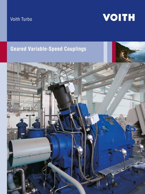
<strong>Geared</strong> <strong>Variable</strong>-<strong>Speed</strong> <strong>Couplings</strong>
<strong>Variable</strong>-<strong>Speed</strong> Drives<br />
We are the experts in hydrodynamic variable-speed drives at <strong>Voith</strong> <strong>Turbo</strong>.<br />
<strong>Voith</strong> <strong>Turbo</strong>, the specialist for hydrodynamic drive, coupling and braking systems for road,<br />
rail and industrial applications, as well as for ship propulsion systems, is a Group Division<br />
of <strong>Voith</strong> GmbH.<br />
<strong>Voith</strong> is one of the largest family-owned companies in Europe with a workforce of around<br />
39 000, with sales of EUR 5.1 billion in the 2008 / 2009 fiscal year and 280 locations worldwide.<br />
The company is active in the energy, oil and gas, paper and raw materials industries,<br />
as well as transportation and automotive markets around the world.
<strong>Geared</strong> variable-speed couplings<br />
Precise control of maximum powers 2<br />
How will you benefit? 3<br />
<strong>Geared</strong> variable-speed couplings<br />
with modular design 4<br />
<strong>Geared</strong> variable-speed couplings<br />
for high-speed driven machines 5<br />
How to select the right coupling 6-7<br />
How to operate the coupling 8<br />
Product range<br />
for high-speed driven machines 9<br />
<strong>Geared</strong> variable-speed couplings<br />
for low-speed driven machine 10-11
2<br />
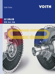
Precise control<br />
of maximum powers<br />
<strong>Voith</strong> <strong>Turbo</strong> is the largest manufacturer of geared variable-speed<br />
couplings worldwide. Over 4 000 drives have been supplied so far<br />
and are operating successfully. Powers up to 60 000 kW and speeds<br />
up to 20 000 rpm are possible. Drives with geared variable-speed<br />
couplings are renowned all over the world for their outstanding<br />
features and customer benefits in a wide range of applications,<br />
i.e. in power plants, in the petrochemical industry, the chemical<br />
industry, the iron and steel industry as well as many others.<br />
Economical operation with excellent<br />
reliability is a priority in modern<br />
power plants. Whether they are<br />
installed in boiler feed pump or fan<br />
drives, in thermal power stations,<br />
in combined cycle power plants or<br />
nuclear power plants, <strong>Voith</strong> geared<br />
variable-speed couplings meet<br />
these requirements, both in the<br />
feed water and in the cooling water<br />
circuit of the power plant.<br />
Controlling the speed of the driven<br />
machine provides accurate and<br />
energy-saving adaptation of power<br />
to the operating point of the plant.<br />
In pump and compressor drives in<br />
chemical and petrochemical industry,<br />
the geared variable-speed<br />
couplings ensure that driven<br />
machines operate more economically.<br />
<strong>Voith</strong> <strong>Turbo</strong> has the perfect<br />
geared variable-speed coupling for<br />
virtually all requirements – be it the<br />
smooth acceleration of motor and<br />
driven machine or the precise and<br />
dynamic adaptation of the speed of<br />
driven machine.<br />
Offshore or onshore, in extremely<br />
hot or cold temperatures, on platforms,<br />
pipeline stations or in the<br />
desert – <strong>Voith</strong> geared variablespeed<br />
couplings have been<br />
designed and built to withstand<br />
rough and extreme conditions,<br />
year after year, with a minimum<br />
of main tenance and maximum<br />
reliability and availability. Designs<br />
to API specifications are available<br />
also.
Applications<br />
Power plants Petrochemical industry Chemical industry<br />
n Boiler feed pumps<br />
n Boiler fans<br />
n Circulating pumps<br />
n Coal mills<br />
Combined with a robust squirrelcage<br />
motor, geared variable-speed<br />
couplings have proven themselves<br />
as the preferred choice when competing<br />
against alternative drive<br />
systems.<br />
n Pipeline pumps<br />
n Crude-oil pumps<br />
n Injection pumps<br />
n Pipeline compressors<br />
n Process compressors<br />
n Compressors<br />
n Fans<br />
n Centrifugal pumps<br />
How will you benefit?<br />
n Power savings and extension of driven machine life<br />
compared to throttle control; lower operating costs<br />
n Precise load adaptation of driven machines due to<br />
the high control accuracy and fast reaction times<br />
n Reliability > 99.9 %<br />
(Evaluation based on units in operation)<br />
n Vibration damping<br />
n Relieved motor start-up and smooth acceleration<br />
of heavy masses<br />
n Robust and compact design<br />
n Easy maintenance, low maintenance costs<br />
n Long service life<br />
3
<strong>Geared</strong> variable-speed couplings<br />
with modular design<br />
The modular geared variable-speed<br />
coupling is a further development<br />
of the proven geared variablespeed<br />
coupling design. The gear<br />
stage and the hydrodynamic variable-speed<br />
coupling are provided<br />
in a range of separate modules but<br />
with a common interface so that<br />
they can be combined to provide<br />
the optimum solution for a particular<br />
driven machine power and speed.<br />
The advantages of this design<br />
are obvious:<br />
n Increased technical flexibility<br />
n Optimum adaptation by combining<br />
gearbox and coupling<br />
n Integrated rapid-start device<br />
n Compact design, short delivery<br />
times<br />
n Easy maintenance<br />
Scoop tube with electro-hydraulic actuator and<br />
mechanically operated oil circulation control valve:<br />
improved dynamics, increased precision, low<br />
auxiliary power, compact design, no electromechanical<br />
con nect ing members.<br />
4
5<br />
<strong>Geared</strong> variable-speed couplings<br />
for high-speed driven machines<br />
Design and function<br />
<strong>Voith</strong> geared variable-speed couplings<br />
combine mechanical gears<br />
and a hydrodynamic variablespeed<br />
turbo coupling in one common<br />
housing. The oil reservoir is<br />
bolted to the bottom of the housing.<br />
Depending on the application or<br />
the design, the gear stage is either<br />
arranged on the input or on the<br />
output side of the coupling.<br />
The cou pling fill can be varied as<br />
needed during operation by means<br />
of the scoop tube. As a result, the<br />
speed and power transmitted to the<br />
driven machine can be controlled<br />
steplessly.<br />
<strong>Voith</strong> geared variable-speed<br />
coupling type R..K..M<br />
Type R..K..M<br />
PI PS PS<br />
Oil supply<br />
Both working and lube oil are<br />
supplied from the integrated oil<br />
tank, but have separate circuits.<br />
The oil system can also be used<br />
to supply both the motor and the<br />
driven machine with lube oil.<br />
Design<br />
The design of a geared variablespeed<br />
coupling is essentially<br />
determined by the power and the<br />
speed of the driven machine.<br />
1<br />
2<br />
9<br />
7<br />
8<br />
3<br />
12<br />
4<br />
PDS<br />
11<br />
10<br />
5<br />
4…20 mA<br />
1 Gear stage<br />
2 Hydrodynamic variable-<br />
speed coupling<br />
3 Scoop tube<br />
4 Electro-hydraulic positioning<br />
control (VEHS)<br />
5 Working oil cooler<br />
6 Lube oil cooler<br />
7 Main lube oil pump<br />
8 Oil circulation control<br />
valve<br />
9 Working oil pump<br />
10 Auxiliary lube oil pump<br />
11 Duplex filter<br />
12 Oil reservoir<br />
6
Power [kW x 1000]<br />
60<br />
50<br />
40<br />
30<br />
20<br />
10<br />
5<br />
4<br />
3<br />
2<br />
1<br />
0,3<br />
R 120<br />
R 119<br />
R 118<br />
R 117<br />
How to select<br />
the right coupling<br />
The power diagrams show the<br />
powers transmitted in relation to<br />
the input and output speed for the<br />
various coupling types and sizes.<br />
Input speed = 1500 rpm (50 Hz countries)<br />
R 111 K 630<br />
R 110 K 630<br />
R 19 K…M<br />
R 18 K…M<br />
R 17 K…M<br />
R 16 K…M<br />
R 120/119 GS<br />
R 119/118 GS<br />
R 118/117 GS<br />
R 15 K…M<br />
550<br />
600<br />
500<br />
450<br />
400<br />
R 14 K…M<br />
R 12 K…M<br />
R 110/111 KGS<br />
R 18/19 KGS-14<br />
R 10 K…M<br />
R 16/17 KGS<br />
R 8 K…M<br />
1 2 3 4 5 6 7 8 9 10 15 20<br />
<strong>Speed</strong> [rpm x 1000]<br />
Power [kW x 1000]<br />
Input speed = 1800 rpm (60 Hz countries)<br />
60<br />
50<br />
40<br />
30<br />
20<br />
10<br />
5<br />
4<br />
3<br />
2<br />
1<br />
0,3<br />
R 120<br />
R 119<br />
R 118<br />
R 117<br />
R 111 K 630<br />
R 110 K 630<br />
R 19 K…M<br />
R 18 K…M<br />
R 17 K…M<br />
R 16 K…M<br />
R 120/119 GS<br />
R 119/118 GS<br />
R 118/117 GS<br />
R 15 K…M<br />
600<br />
550<br />
500<br />
450<br />
R 110/111 KGS<br />
R 18/19 KGS-14<br />
400 R 16/17 KGS<br />
R 14 K…M<br />
R 12 K…M<br />
R 10 K…M<br />
R 8 K...M<br />
1 2 3 4 5 6 7 8 9 10 15 20<br />
<strong>Speed</strong> [rpm x 1000]<br />
6
Power [kW x 1000]<br />
60<br />
50<br />
40<br />
30<br />
20<br />
10<br />
5<br />
4<br />
3<br />
2<br />
1<br />
R 115<br />
R 114<br />
R 113<br />
R 111 K 630<br />
R 110 K 630<br />
R 19 K…M<br />
R 18 K…M<br />
R 17 K…M<br />
R 16 K…M<br />
Design to API standard are also<br />
available. The size of the machine<br />
then depends on the specified API<br />
service factor.<br />
Input speed = 3000 rpm (50 Hz countries)<br />
R 115 GS<br />
R 115 GS<br />
R 114 GS 550<br />
R 114 GS<br />
R 113 GS<br />
R 15 K…M<br />
500/450<br />
0,3<br />
1 2 3 4 5 6 7 8 9 10 15 20<br />
<strong>Speed</strong> [rpm x 1000]<br />
400<br />
R 14 K…M<br />
R 12 K…M<br />
R 110/111 KGS<br />
R 18/19 KGS-14<br />
R 10 K…M<br />
R 16/17 KGS<br />
R 8 K…M<br />
R 19 GS...M<br />
R 18 GS...M<br />
R 17 GS...M<br />
R 16 GS...M<br />
R 15 GS...M<br />
Power [kW x 1000]<br />
Input speed = 3600 rpm (60 Hz countries)<br />
60<br />
50<br />
40<br />
30<br />
20<br />
10<br />
5<br />
4<br />
3<br />
2<br />
1<br />
R 115<br />
R 114<br />
R 113<br />
R 111 K 630<br />
R 110 K 630<br />
R 19 K…M<br />
R 18 K…M<br />
R 17 K…M<br />
R 16 K…M<br />
R 115 GS<br />
R 115 GS<br />
R 114 GS 550<br />
R 114 GS<br />
R 113 GS<br />
R 15 K…M<br />
500/450<br />
0,3<br />
1 2 3 4 5 6 7 8 9 10 15 20<br />
<strong>Speed</strong> [rpm x 1000]<br />
400<br />
R 14 K…M<br />
R 12 K…M<br />
R 110/111 KGS<br />
R 18/19 KGS-14<br />
R 10 K…M<br />
R 16/17 KGS<br />
R 8 K…M<br />
R 19 GS...M<br />
R 18 GS...M<br />
R 17 GS...M<br />
R 16 GS...M<br />
R 15 GS...M<br />
7
8<br />
How to operate<br />
the coupling<br />
The performance diagram shows<br />
the transmittable coupling torques<br />
TK at different scoop tube positions<br />
as a func tion of the output speed.<br />
The desired output speed becomes<br />
a stable intersection between coupling<br />
torque TK and load torque<br />
(load curve).<br />
Operating Ranges:<br />
I, IV Starting Range<br />
II Control Range<br />
III Overload Range<br />
The shape of the coupling characteristic<br />
curves is given for information<br />
only, since there may be minor<br />
deviations if coupling sizes, circulation<br />
oil flows, oil viscosity, etc. vary.<br />
Performance diagram<br />
T K [%]<br />
125<br />
100<br />
75<br />
50<br />
25<br />
0<br />
Parameters:<br />
T K<br />
s min<br />
30%<br />
20%<br />
10%<br />
0%<br />
Scoop tube position in %<br />
of the full scoop-tube stroke.<br />
Transmitted coupling torque<br />
Minimum slip required<br />
for torque transmission<br />
s = ( 1 – n 2 ) • 100 [%]<br />
n 1<br />
n 1<br />
n 2<br />
input speed<br />
output speed<br />
I<br />
III<br />
40%<br />
50% 60% 70% 80%<br />
II<br />
50 100<br />
Output speed [% of input speed]<br />
Typical load characteristics:<br />
1<br />
2<br />
4<br />
3<br />
IV<br />
1 constant torque<br />
(e.g. positive displacement<br />
pumps and compressors).<br />
2 decreasing torque<br />
(e.g. boiler feed pumps<br />
operating at varying pressures).<br />
3 parabolic torque<br />
(e.g. resistance parabola,<br />
pumps with back pressure,<br />
blowers).<br />
4 decreasing torque<br />
(e.g. boiler feed pumps<br />
operating at fixed pressure).<br />
100%<br />
s min
Type R..KGS<br />
Product range<br />
for high-speed driven machines<br />
Coupling types for specific applications depend on the respective<br />
arrangement of gearbox and coupling and the power and the speed<br />
of the motor and the driven machine.<br />
Type R..K..M (see page 5)<br />
A combination of step-up gear and<br />
variable speed coupling with high<br />
power density, step-up gearing.<br />
Special advantages due to modular<br />
design.<br />
Type R..KGS<br />
A step-up gear is integrated both<br />
at the input and the output side for<br />
particularly high output speeds,<br />
e.g. for high-speed compressors.<br />
Type R..GS<br />
Type R..GS<br />
The coupling is direct-driven by the<br />
motor and adapted to the required<br />
speed of driven machine by the<br />
step-up gear located at the output<br />
side of the coupling; ideal for high<br />
powers and extremely high speeds.<br />
9
10<br />
<strong>Geared</strong> variable-speed couplings<br />
for low-speed driven machines<br />
<strong>Voith</strong> geared variable-speed<br />
coupling type R..A:<br />
1 Gear stage<br />
2 Hydrodynamic variable-<br />
speed coupling<br />
3 Scoop tube (adjustable)<br />
4 Hydrodynamic brake<br />
(optional)<br />
5 Oil supply<br />
6 Working oil cooler<br />
7 Duplex filter<br />
8 Oil pump<br />
Type R..A<br />
The control requirements of low-speed driven machines such<br />
as coal mills, I.D. fans or crude oil pumps, vary greatly.<br />
Depending on the application and for optimum adaptation to<br />
the existing space conditions, the gear stage is designed as<br />
a helical gear or bevel gear.<br />
The variable-speed coupling is<br />
fitted with a helical reduction gear<br />
on the output side. Typical driven<br />
machines are coal mills, crushers,<br />
low-speed pumps and fans.<br />
Design and function<br />
For low-speed driven machines, the<br />
turbo coupling is fitted with a reduction<br />
gear on the output. Coupling<br />
and gear stage are situated in a<br />
common housing, the lower part<br />
of which serves as an oil reservoir.<br />
By adding a <strong>Voith</strong> hydrodynamic<br />
brake (optional), with an appropriate<br />
breaking torque characteristic,<br />
heavy masses of the driven<br />
ma chine can be rapidly decelerated.<br />
Type R..A<br />
7<br />
8<br />
6<br />
Oil supply<br />
Both working and lube oil are supplied<br />
from the integrated oil tank.<br />
The oil system can also be used<br />
to supply both the motor and the<br />
driven machine with oil.<br />
5<br />
2<br />
3<br />
1<br />
4
Type R..B<br />
Type R..KGL<br />
A step gear at the input side and<br />
a reduction gear at the output side<br />
make this type into a fast reacting<br />
and compact coupling used e.g. for<br />
fast respones times, loading pumps<br />
and high powers.<br />
Type R..B<br />
This type of turbo coupling is fitted<br />
with a step-up gear on the output<br />
side. <strong>Geared</strong> variable-speed couplings<br />
for low-speed driven machines<br />
with high inertia, e.g. coal mills.<br />
Type R..KGL<br />
<strong>Geared</strong> variable-speed<br />
coupling type R..B<br />
11
<strong>Voith</strong> <strong>Turbo</strong> GmbH & Co. KG<br />
<strong>Variable</strong>-<strong>Speed</strong> Drives<br />
<strong>Voith</strong>str. 1<br />
74564 Crailsheim, Germany<br />
Tel. +49 7951 32-261<br />
Fax +49 7951 32-650<br />
vs.drives@voith.com<br />
www.voithturbo.com/variable-speed<br />
cr269en, aik-S&F / SVG, 11.2010, 3 000. Dimensions and illustrations without obligation. Subject to modifications.