English - Meijer Special Equipment
English - Meijer Special Equipment
English - Meijer Special Equipment

Create successful ePaper yourself
Turn your PDF publications into a flip-book with our unique Google optimized e-Paper software.
A trademark of <strong>Meijer</strong> <strong>Special</strong> <strong>Equipment</strong><br />
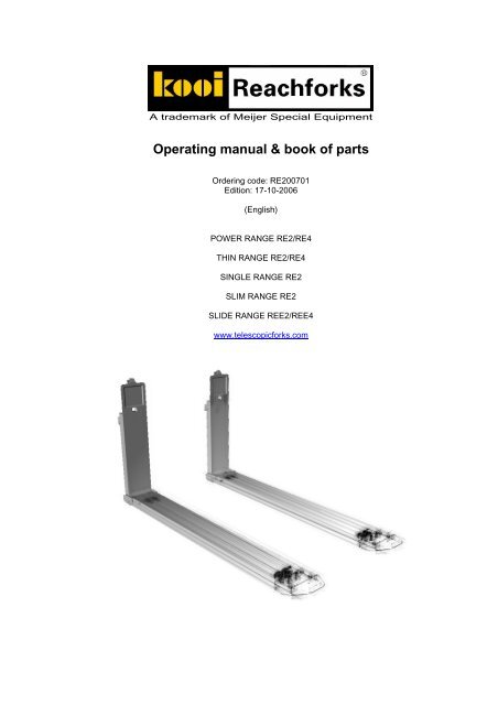
Operating manual & book of parts<br />
Ordering code: RE200701<br />
Edition: 17-10-2006<br />
(<strong>English</strong>)<br />
POWER RANGE RE2/RE4<br />
THIN RANGE RE2/RE4<br />
SINGLE RANGE RE2<br />
SLIM RANGE RE2<br />
SLIDE RANGE REE2/REE4<br />
www.telescopicforks.com
Table of contents<br />
A trademark of <strong>Meijer</strong> <strong>Special</strong> <strong>Equipment</strong><br />
1. Comment..............................................................................................................2<br />
2. Foreword..............................................................................................................3<br />
3. Introduction .........................................................................................................4<br />
4. Identification ........................................................................................................5<br />
4.1. Type specifications..................................................................................................................... 5<br />
4.2. Explanation of type plate ............................................................................................................ 6<br />
4.3. Explanation of indication type..................................................................................................... 7<br />
4.4. Capacity...................................................................................................................................... 7<br />
5. Safety....................................................................................................................9<br />
6. Instructions for use...........................................................................................10<br />
7. Mounting instructions.......................................................................................11<br />
7.1. Prescriptions............................................................................................................................. 11<br />
7.2. Mounting instructions for telescopic forks with a separate flow divider ................................... 12<br />
7.2.1. Recommended oil flow and hose diameter........................................................................... 13<br />
7.2.2. Putting the telescopic forks into operation ............................................................................ 13<br />
7.3. Protecting the telescopic forks ................................................................................................. 13<br />
8. Inspection and maintenance ............................................................................14<br />
8.1. Maintenance schedule ............................................................................................................. 14<br />
8.2. Trouble chart for telescopic forks with a separate flow divider ................................................ 17<br />
8.3. Instructions for replacing hydraulic parts.................................................................................. 18<br />
8.4. Ordering spare parts ................................................................................................................ 19<br />
Appendices ..............................................................................................................20<br />
© MEIJER SPECIAL EQUIPMENT 2005 1
A trademark of <strong>Meijer</strong> <strong>Special</strong> <strong>Equipment</strong><br />
1. Comment<br />
©Copyright 2005, <strong>Meijer</strong> <strong>Special</strong> <strong>Equipment</strong>. All rights reserved.<br />
Information provided in this manual, including but not limited to pictures and text, may not be<br />
reproduced or distributed without prior written consent of <strong>Meijer</strong> <strong>Special</strong> <strong>Equipment</strong>, if not stated<br />
otherwise.<br />
The information in this manual is provided without any form of guarantee. <strong>Meijer</strong> <strong>Special</strong> <strong>Equipment</strong><br />
shall in no case be liable for injuries and damages resulting from the use of this manual.<br />
Note that the information in this manual can be modified at any time without prior notice. Note also that<br />
this manual can contain technical inaccuracies and misprints. <strong>Meijer</strong> <strong>Special</strong> <strong>Equipment</strong> does its best<br />
to prevent mistakes in this manual, but can not guarantee it. If you come across misprints or technical<br />
inaccuracies or if you have suggestions, please, let us know about it.<br />
KOOI Reachforks ® is a registered trademark of <strong>Meijer</strong> <strong>Special</strong> <strong>Equipment</strong>.<br />
Other trademarks or product names used in this manual, but that are not mentioned here, are<br />
trademarks of their respective holders.<br />
2 © MEIJER SPECIAL EQUIPMENT 2005
2. Foreword<br />
A trademark of <strong>Meijer</strong> <strong>Special</strong> <strong>Equipment</strong><br />
<strong>Meijer</strong> <strong>Special</strong> <strong>Equipment</strong> is the world biggest manufacturer of hydraulic retractable lift truck forks,<br />
which are manufactured under the brand name KOOI Reachforks ®. The telescopic forks were<br />
introduced in 1980 by KOOI BV, manufacturer of the collapsible fork-lift truck, the so-called Kooi-AAP,<br />
but were manufactured by <strong>Meijer</strong> BV. From November 2000 <strong>Meijer</strong> <strong>Special</strong> <strong>Equipment</strong> (division of<br />
<strong>Meijer</strong> Holding) along with production is also responsible for the marketing and sales of the telescopic<br />
forks.<br />
With your new telescopic forks you have acquired a reliable product that meets the highest quality and<br />
consumer requirements. Before you start using the telescopic forks you should know how to use the<br />
telescopic forks correctly. This manual tells you everything that you must know about the telescopic<br />
forks. It allows you to optimally operate the telescopic forks. Moreover, our After Sales Department is<br />
always ready to render you technical support.<br />
KOOI Reachforks ® meet the following quality standards:<br />
1. ISO 9001 – 2000 - Quality Management System<br />
2. ISO 13284 - Fork arm extensions and telescopic fork arms<br />
3. ISO 4406 - Hydraulic fluid power – Fluids – Method for coding level of contamination by solid<br />
particles<br />
4. ISO 2328 - Fork-lift trucks – forks on type fork arms and fork arm carriages<br />
5. CE (98/37) EC - Machinery Directive<br />
6. EN 729-2 - Quality requirements for welding. Fusion welding of metallic materials. Part 2<br />
Comprehensive quality requirements<br />
A random selection of telescopic forks undergoes a dynamic endurance test according to ISO 2330.<br />
© MEIJER SPECIAL EQUIPMENT 2005 3
A trademark of <strong>Meijer</strong> <strong>Special</strong> <strong>Equipment</strong><br />
3. Introduction<br />
The KOOI Reachforks ® are hydraulic retractable lift truck forks. They are designed in such a way that<br />
minimum maintenance is necessary, which allows to reach the most possible life span. To achieve<br />
this it is really important that the maintenance is performed according to the instructions of the<br />
manufacturer. The aim of this instruction manual is to acquaint you with the telescopic forks. We also<br />
advise you to study this instruction manual carefully before you start mounting the telescopic forks and<br />
as you operate them later on.<br />
The manufacturer reserves the right to modify specifications without prior publications. Because we<br />
are constantly striving to improve the product it may happen that the pictures in this manual do not<br />
coincide with the telescopic forks that you have acquired. That is why it is important to mention the<br />
type and serial number as you order spare parts or inquire for information. In the appendices there are<br />
figures and specification tables of all types of telescopic forks, so that you may state the<br />
corresponding article number when you order spare parts.<br />
4 © MEIJER SPECIAL EQUIPMENT 2005
4. Identification<br />
A trademark of <strong>Meijer</strong> <strong>Special</strong> <strong>Equipment</strong><br />
In this chapter the information that is stated on the type plate is explained. This information contains<br />
technical specifications of the telescopic fork and is necessary when ordering spare parts. So, it is<br />
important to know what information is stated on the type plate and how this information can be used.<br />
4.1. Type specifications<br />
The following data should be specified when ordering spare parts or making inquiries. The serial<br />
number and type are stated on the type plate of each telescopic fork (see Figure 4.1). These<br />
specifications are also engraved on the side of each inner fork.<br />
Type, Serial Number, Production Year:<br />
Figure 4.1 Position of type plate and engraved specifications<br />
Manufacturer’s name : <strong>Meijer</strong> <strong>Special</strong> <strong>Equipment</strong><br />
Manufacturer’s address : Oudebildtdijk 894<br />
9079 NG Sint Jacobiparochie<br />
The Netherlands<br />
Tel. : 0031 518 492929<br />
Fax. : 0031 518 492915<br />
Websites : www.mse-forks.com<br />
E-mail : info@mse-forks.com<br />
Type Plate<br />
Engraved data<br />
© MEIJER SPECIAL EQUIPMENT 2005 5
A trademark of <strong>Meijer</strong> <strong>Special</strong> <strong>Equipment</strong><br />
4.2. Explanation of type plate<br />
The type plate is the plate that is located on the upper side of each telescopic fork. The type plate is<br />
mounted on the left as well as on the right fork. Both left and right must be seen from the positions of<br />
the fork-lift truck driver. The type plate contains important information about the technical<br />
specifications of the telescopic fork. Figure 4.2 shows an example of a type plate. The letters in the left<br />
plate can be found in Table 4.1 that represents the description and the measuring unit. The right plate<br />
is an example of how the type plate can be filled in.<br />
Figure 4.2 Type plate of a telescopic fork<br />
Letter Description Measuring unit<br />
A Indication of type<br />
B Production year<br />
C Serial number (L = left / R = right)<br />
D Dead weight Kg<br />
E Centre of gravity Mm<br />
F Capacity retracted Kg<br />
G Capacity extended Kg<br />
H Load centre retracted Mm<br />
I Load centre extended Mm<br />
J Maximum operating pressure MPa (1 MPa = 10 bar)<br />
Table 4.1 Description of the specifications on a type plate of a telescopic fork<br />
6 © MEIJER SPECIAL EQUIPMENT 2005
4.3. Explanation of indication type<br />
A trademark of <strong>Meijer</strong> <strong>Special</strong> <strong>Equipment</strong><br />
Often A at Figure 4.1 contains the type of the telescopic fork. From the type code again various<br />
information can derived. Table 4.2 gives the description of the various sections of the type code.<br />
Here is an example:<br />
RE4-35-1350-1000<br />
Section of Description Measuring<br />
indication type<br />
unit<br />
RE Fork type (in this case telescopic fork with separate flow divider)<br />
4 Number of cylinders per set of telescopic forks<br />
35 Total capacity of a set of telescopic forks / LC 600mm x 100 kg<br />
1100 Retracted fork length mm<br />
0750 Stroke (length difference between retracted and extended fork) mm<br />
Table 4.2 Various sections of the type code and their description<br />
4.4. Capacity<br />
The type plate, which is mounted at the upper side of the telescopic fork, shows among other things<br />
the maximum carrying capacity per telescopic fork. This data is also engraved on the side of the<br />
telescopic fork. With the following load diagram the capacity per telescopic fork or per couple of<br />
telescopic forks can be defined for each load distance. The correction factors are shown vertically and<br />
the load distances are shown horizontally counted in mm from the front side of the back of the fork. On<br />
the following page an example of the operation is given.<br />
correction factor<br />
1,1<br />
1<br />
0,9<br />
0,8<br />
0,7<br />
0,6<br />
0,5<br />
0,4<br />
0,3<br />
0,2<br />
0,1<br />
0<br />
600 800 1000 1200 1400 1600 1800 2000 2200<br />
Load centre (mm)<br />
Figure 4.3 Correction factors for the maximum capacity at a given load centre<br />
© MEIJER SPECIAL EQUIPMENT 2005 7
A trademark of <strong>Meijer</strong> <strong>Special</strong> <strong>Equipment</strong><br />
We take as an example the filled in type plate from Figure 4.2 with the type RE4-35-1350-1000. The<br />
maximum capacity of both telescopic forks is 35 x 100 = 3500 kg at a load centre of 600 mm. That<br />
means that the maximum capacity of one telescopic fork is 3500 / 2 = 1750 kg at a load centre of 600<br />
mm. If the telescopic forks are extended you must look at Figure 4.3 to calculate the new maximum<br />
capacity at the corresponding load centre. If the load centre lies e.g. at 1200 mm then Figure 4.3<br />
shows here a correction factor of 0,5. So the maximum capacity of this telescopic fork at a load centre<br />
of 1200 mm is 1750 x 0.5 = 875 kg.<br />
!<br />
Warning:<br />
Figure 4.3 applies only to the telescopic forks. The residual capacity<br />
of the fork-lift truck with the telescopic forks must be provided for by<br />
an authorised fork-lift truck dealer.<br />
8 © MEIJER SPECIAL EQUIPMENT 2005
5. Safety<br />
A trademark of <strong>Meijer</strong> <strong>Special</strong> <strong>Equipment</strong><br />
Safety starts with the fork-lift truck driver. That is why we advise that the driver of the fork-lift truck<br />
possesses a recognized diploma of a fork-lift truck driver.<br />
Furthermore it is important to observe the following safety instructions:<br />
1. Do not load the telescopic forks above the values defined by the manufacturer, concerning lifting<br />
capacity and load centre.<br />
2. Pull the load in if it is possible. ATTENTION, telescopic forks of the type REE are extension forks,<br />
never pull them in with a load on.<br />
3. Retract the telescopic forks during driving if there is no load on them.<br />
4. Always drive with the telescopic forks in the lowest possible position.<br />
5. Never drag the telescopic forks over the ground when driving.<br />
6. Never allow riding on the telescopic forks or load.<br />
7. Telescopic forks with defects may not be used until they are expertly repaired or replaced.<br />
8. Before you start performing service work on the telescopic forks you must make sure that the fork-<br />
lift truck is switched off and that there is no more pressure in the hydraulic system (remove the<br />
ignition key).<br />
9. The load should always be carried by the two telescopic forks as proportionally as possible.<br />
10. Always keep the exterior of the outer forks free from grease and oil.<br />
All abovementioned points must be read and understood by the fork-lift driver.<br />
!<br />
!<br />
!<br />
Warning:<br />
Never exceed the maximum carrying capacity of the fork-lift truck,<br />
irrespective of the carrying capacity of the telescopic forks.<br />
Warning:<br />
Never walk under the telescopic forks.<br />
Warning:<br />
Applicable only to telescopic forks with a high<br />
palletstop (type Y2 or Y3), that with a retracted<br />
fork is at a distance of 50mm or less from the<br />
back of the fork (from palletstop front to the front<br />
side of the back of the fork).<br />
When retracting avoid squeezing limbs or goods<br />
between the back of the fork and the palletstop.<br />
This may result in serious injury or damage of<br />
goods!<br />
© MEIJER SPECIAL EQUIPMENT 2005 9
A trademark of <strong>Meijer</strong> <strong>Special</strong> <strong>Equipment</strong><br />
6. Instructions for use<br />
Telescopic forks offer the possibility to load and unload a lorry from one side, to stack goods at<br />
warehouses double-deep, to pick up two pallets at a time, and they may be used as extension forks<br />
when operating with pallets of various dimensions.<br />
The telescopic forks are easy to mount and to demount. The telescopic forks must be tuned to the<br />
fork-lift truck for the purpose that they are intended for. The final capacity must be defined by an<br />
authorised fork-lift truck dealer. On the type plate of the fork-lift truck the capacity must be adapted to<br />
the new combination of fork-lift truck and telescopic forks. It is advisable that the fork-lift truck driver is<br />
professionally trained in the use of telescopic forks.<br />
!<br />
!<br />
!<br />
Attention!:<br />
The contact of the telescopic forks with the ground, during driving and<br />
during pick-up of a load, must be avoided as far as possible. This<br />
prevents wear at the bottom of the outer forks. To prevent this wear<br />
wear-resistant pads can be welded to the underside of the outer<br />
forks.<br />
Attention!:<br />
When moving in reverse take care that the telescopic forks do not<br />
drag over the ground. This can result in damage to outer fork as well<br />
as to piston rods.<br />
Attention!:<br />
Telescopic forks of the type REE are extension forks. This type of<br />
telescopic forks is not intended to be extended and retracted when<br />
loaded. Retract or extend the telescopic forks to the required length<br />
before picking up a load.<br />
10 © MEIJER SPECIAL EQUIPMENT 2005
7. Mounting instructions<br />
A trademark of <strong>Meijer</strong> <strong>Special</strong> <strong>Equipment</strong><br />
In this chapter first of all several prescriptions are listed that must be observed during service work on<br />
the telescopic forks, irrespective of the type. In 7.2 the telescopic forks with a separate flow divider are<br />
dealt with. 7.3 tells about what can be done to reduce wear at the bottom of the telescopic forks.<br />
7.1. Prescriptions<br />
There are several prescriptions that must be observed during mounting operations, inspection or<br />
maintenance of the telescopic forks.<br />
During all service work on the telescopic forks, the forklift truck should be switched off and the ignition<br />
key must be removed.<br />
When performing maintenance the hydraulic system of the fork-lift truck must have no pressure.<br />
Position the telescopic forks on the convenient ergonomic height to prevent backaches.<br />
Wear safe working clothes, shoes and safety goggles.<br />
When disconnecting the telescopic forks from the fork carrier the connection couplings of the<br />
telescopic forks must be unplugged to protect the hydraulic system from dirt that might get inside.<br />
Nothing can be welded to the telescopic forks without written consent of the manufacturer. If<br />
something is welded to the telescopic forks without written consent the guaranty on the telescopic<br />
forks terminates.<br />
© MEIJER SPECIAL EQUIPMENT 2005 11
A trademark of <strong>Meijer</strong> <strong>Special</strong> <strong>Equipment</strong><br />
7.2. Mounting instructions for telescopic forks with a separate flow divider<br />
(RE2, RE4, REE2 and REE4)<br />
To achieve the most optimal operation of your telescopic forks after the mounting you should observe<br />
the following mounting instructions:<br />
1. On the type plates of the telescopic forks there are an L and an R displayed. Mount these<br />
telescopic forks accordingly on the right and on the left sides viewed from the position of the fork-<br />
lift truck driver.<br />
2. Slide the telescopic forks onto the fork carrier and make sure that the locking pin fits into one of<br />
the fork carrier notches.<br />
3. The flow divider must be mounted on a safe and protected spot.<br />
4. Connect the enclosed hydraulic hoses of the telescopic forks and the hoses of the fork-lift truck<br />
according to Figure 7.1 and pay attention to the letters that are engraved at the top of the fork as<br />
well as in the flow divider.<br />
5. Make sure that the hydraulic connections are carefully tightened and secured.<br />
6. The maximum allowable working pressure of the telescopic forks is 200 bars.<br />
Figure 7.1 A depiction of how the hydraulic hoses for telescopic forks with a separate flow divider must be connected<br />
12 © MEIJER SPECIAL EQUIPMENT 2005
7.2.1. Recommended oil flow and hose diameter<br />
A trademark of <strong>Meijer</strong> <strong>Special</strong> <strong>Equipment</strong><br />
Table 7.1 shows what the recommended hose diameter is at a certain oil flow for the telescopic forks<br />
with a separate flow divider. The recommended flow divider type is also shown.<br />
Type of telescopic fork Recommended oil flow Recommended hose Flow divider type<br />
(L/min)<br />
diameter<br />
RE2/REE2/RE4/REE4 8 – 25 ¼” RE0100000<br />
Table 7.1 Which hoses and flow divider to use for which oil flow<br />
If the oil flow is more than 25 l/min, it will have little effect on the speed. It is also recommended to stay<br />
below this value, so that the pump does not constantly have to deliver the maximum pressure and so<br />
no oil pumps through the safety valve to the tank. This will also require less energy.<br />
7.2.2. Putting the telescopic forks into operation<br />
First you should make sure that there is no more air in the system. You can do this in the following<br />
way:<br />
Extend and retract the telescopic forks ten times.<br />
Bend the mast of the fork-lift truck several times forward and backward.<br />
Extend and retract the telescopic forks ten times.<br />
Then control if the hoses can go all over long enough and check if the system leaks no oil.<br />
7.3. Protecting the telescopic forks<br />
To avoid that the telescopic forks come into contact with the ground we advise to place a plastic<br />
sleeve on the lift cylinder in such a way that the telescopic forks just do not contact the ground. The<br />
lifting chains of the fork-lift truck can be somewhat shortened, which will have the same effect. Always<br />
consult your dealer or manufacturer if you want to perform such a modification.<br />
© MEIJER SPECIAL EQUIPMENT 2005 13
A trademark of <strong>Meijer</strong> <strong>Special</strong> <strong>Equipment</strong><br />
8. Inspection and maintenance<br />
The telescopic forks operate with a closed self-lubricating hydraulic system. The telescopic forks are<br />
delivered with Rando HD 32 hydraulic oil.<br />
The servicing that must be performed to keep the telescopic forks in good condition is very limited.<br />
What is important is that the servicing is carried out in time and correctly.<br />
Check the telescopic forks each day for damage and oil leakage. If there is indeed damage or leakage<br />
this should be reported to the person in charge. During all service work on the telescopic forks the<br />
fork-lift truck should be switched off, the ignition key must be removed and there may be no more<br />
pressure in the system.<br />
Consult the maintenance schedule for further inspection. In some cases it may happen that the<br />
maintenance schedule must be adjusted, for example in extra polluted environment. Plugs should<br />
then be replaced more often, in particular the wiper ring.<br />
The telescopic forks must be tested again minimum once per year by a specialist according to the ISO<br />
5057 norm. The results of the test should be kept in a test book.<br />
In case parts of the piston or the cylinder head must be replaced, this should be carried out by a<br />
skilled person or contact an officially authorised importer listed on the website<br />
(www.telescopicforks.com).<br />
8.1. Maintenance schedule<br />
Table 8.1 shows which parts must be controlled, what actions must be taken and when this must be<br />
done. The numbers of the description correspond to the telescopic fork in Figure 8.1 (page 16).<br />
Description Daily Weekly 6 months Yearly<br />
or 1000 hours or 2000 hours<br />
1 Inner fork – lubricating upper and underside<br />
with grease<br />
X<br />
2 Checking inner fork for leakage X<br />
3 Checking wear resistant strips for wear (for<br />
REE: also check wear pad bottom inner fork)<br />
X<br />
4 Checking the underside of outer forks for<br />
wear, especially at the back side<br />
X<br />
5 Checking for dirt in outer casing and eventual<br />
removal<br />
X<br />
6 Checking cylinder head for leakage X<br />
7 Checking inner fork according to ISO 5057 X<br />
Table 8.1 Maintenance schedule<br />
14 © MEIJER SPECIAL EQUIPMENT 2005
Here comes a commentary on the maintenance schedule from Table 8.1:<br />
A trademark of <strong>Meijer</strong> <strong>Special</strong> <strong>Equipment</strong><br />
1. As lubricating grease we recommend Novatex EP 2, this is a special type of calcium grease for<br />
lubrication of heavy loaded sliding parts that protects against wear and corrosion.<br />
2. In case of leakage in the curve of the inner fork immediately demount the telescopic forks from the<br />
fork-lift truck and take contact with your dealer. In case of leakage of couplings tighten or replace<br />
them.<br />
3. When the wear resistant strips are thinner than 1,5 mm, they should be replaced or filled up with<br />
filling plates. For REE: When the hardened wear pad at the bottom of the telescopic fork is so<br />
worn-out that it is level with the bottom of the outer fork, it should be replaced. This is to prevent<br />
excess wear of outer and inner forks. The remainder of the old wear pad must be removed and<br />
the new wear pad must be welded under the telescopic fork according to the welding figure in<br />
Appendix 13. ATTENTION: Take out interior work (piston, piston rod and cylinder head) from<br />
telescopic fork BEFORE welding.<br />
4. When the hardened wear pad in the heel of the outer fork is level with the underside of the outer<br />
fork or is even thinner than the original thickness of the outer fork then the outer fork should be<br />
replaced.<br />
5. Eventual dirt in the front part of the outer casing can affect the stroke length of the telescopic<br />
forks. Depending on the application it may need to be controlled either more or less often.<br />
6. The wiper ring can be easily controlled if the outer casing is taken off (for instructions on removing<br />
the outer fork, see par. 8.4).<br />
7. The international standard ISO 5057 must be applied for checking your telescopic lift truck forks,<br />
except for paragraph 5.6.1 because the inner fork may not be subject to wear.<br />
© MEIJER SPECIAL EQUIPMENT 2005 15
A trademark of <strong>Meijer</strong> <strong>Special</strong> <strong>Equipment</strong><br />
For more information about Novatex EP 2 and Rando HD 32 visit www.texaco.com.<br />
Figure 8.1 Maintenance schedule<br />
Required tools:<br />
• ½ “ Socket drive<br />
• Cilinderhead spanner 30/35*<br />
• Cilinderhead spanner 25**<br />
•<br />
3 /16” Hexagonal / Allen key<br />
• 22mm Open ended spanner<br />
• Hamer + Ø10 punch<br />
• */**Are only available at<br />
<strong>Meijer</strong> <strong>Special</strong> <strong>Equipment</strong> –<br />
*ordering number:<br />
RE0058011<br />
• **ordeling number<br />
RE0058012<br />
16 © MEIJER SPECIAL EQUIPMENT 2005
A trademark of <strong>Meijer</strong> <strong>Special</strong> <strong>Equipment</strong><br />
8.2. Trouble chart for telescopic forks with a separate flow divider<br />
(RE2, RE4, REE2 and REE4)<br />
Symptom Possible cause Possible solution<br />
Forks do not move evenly Hydraulic hoses connected<br />
wrong<br />
Dirt between inner and outer<br />
forks<br />
Piston leakage<br />
Length of 4 hoses is not equal<br />
Flow divider damaged<br />
Connect hoses according to the<br />
scheme (fig. 7.2)<br />
Empty outer fork<br />
Replace piston plug<br />
Mount equal hoses<br />
Forks move without control Leakage in the control valve<br />
Replace flow divider<br />
Consult your fork-lift truck dealer<br />
Oil leaks from the forks Couplings leak<br />
Tighten again or replace<br />
Cylinder head plug damaged Replace cylinder head plug<br />
Fork is cracked<br />
Take the fork immediately from<br />
the fork carrier and contact your<br />
fork-lift truck dealer<br />
Forks move irregularly Control valve/pump worn-out Consult your fork-lift truck dealer<br />
Not enough oil flow<br />
Consult your fork-lift truck dealer<br />
One outer fork first stands still<br />
during retraction and then<br />
suddenly retracts<br />
Spiral clamping bush broken Replace spiral clamping bush<br />
One of the outer forks does not<br />
retract<br />
Spiral clamping bush broken Replace spiral clamping bush<br />
One fork tip hangs lower than One of the forks is plastically Consult your fork-lift truck dealer<br />
the other<br />
distorted by overloading<br />
Wear resistant strip of one fork is Replace wear resistant strips<br />
worn-out more than that of the<br />
other fork<br />
Too much clearance space<br />
between inner and outer fork<br />
Wear resistant strips worn-out<br />
Casing worn-out<br />
Table 8.2 Trouble chart for telescopic forks with a separate flow divider<br />
Replace wear resistant strips<br />
Replace casing<br />
© MEIJER SPECIAL EQUIPMENT 2005 17
A trademark of <strong>Meijer</strong> <strong>Special</strong> <strong>Equipment</strong><br />
8.3. Instructions for replacing hydraulic parts<br />
1. Set the telescopic forks on the hip level, bend the mast forward and remove the ignition key from<br />
the contact.<br />
2. Take the outer fork off by removing the spiral clamping bushes (be careful not to damage the<br />
piston rods).<br />
3. Unscrew the hose couplings a little off the hose above on the rug of the telescopic fork so that the<br />
piston rods do not pull vacuum when demounting the telescopic forks.<br />
4. Unscrew the locking screw situated between the cylinder heads.<br />
5. Place a reservoir under the telescopic forks. Use the cylinder head key to unscrew the cylinder<br />
heads. Take care that the right cylinder head (as viewed from the position of the diver) is<br />
unscrewed first, along with the plastic bung under the locking screw.<br />
6. Carefully pull out the piston rods.<br />
7. The piston can now be unscrewed. To avoid damage to the piston rod it must be clipped onto the<br />
mounting clip. The cylinder head can now be unscrewed from the piston rod.<br />
8. Replace the parts.<br />
9. Remove Loctite from the screw thread of the piston rod.<br />
10. Clean piston rod and screw thread with Loctite 7063.<br />
11. The cylinder head can now be put on the piston rod again.<br />
12. When mounting the piston on the piston rod it must be locked with Loctite 270.<br />
13. Keep the piston rod (along with piston and cylinder head) straight before the cylinder and tap it<br />
carefully directly to the inside.<br />
14. Smear the screw thread of the cylinder head with Copaslip.<br />
15. Tighten again the cylinder head carefully with a cylinder head key.<br />
16. As all piston rods sit again in their place, the locking screw must be screwed up again above the<br />
plastic bung.<br />
17. Now the hose couplings of hose must be screwed up.<br />
18. Take care that the piston rods should be unscrewed for about 150 mm.<br />
19. The outer forks can be now mounted again. Take care that the clamps of the piston rods are<br />
located exactly under the holes in the outer fork. Insert a screwdriver or a bolt in one hole and hit<br />
the new spiral clamping bushes in the other gat with a hard hammer. The screwdriver or the bolt<br />
can be taken from the hole and now the spiral clamping bushes can be knocked in here.<br />
20. Start the fork-lift truck and extend and retract the telescopic forks several times.<br />
18 © MEIJER SPECIAL EQUIPMENT 2005
Object Turning moment (N⋅m)<br />
All pistons on piston rod 100<br />
Table 8.3 Table Turning moment<br />
For more information about the various Loctite products visit www.loctite.com.<br />
For more information about Copaslip visit www.kroon-oil.com.<br />
8.4. Ordering spare parts<br />
A trademark of <strong>Meijer</strong> <strong>Special</strong> <strong>Equipment</strong><br />
With the types RE4-25, RE4-35 and RE4-45 of the Power Range and with a stroke (see Paragraph<br />
4.3.) of more than 1200 mm a rod thickness of 20 mm is operated with, this should be taken into<br />
consideration when ordering pistons, cylinder heads and plugs. Besides, deviations in bore diameter<br />
are engraved on the side of the telescopic forks.<br />
In case a separate piston, cylinder head or only a plug, wiper ring or guide ring must be ordered, it is<br />
recommended to order them mounted and all together to avoid problems at mounting.<br />
For ordering the piston rods instead of XXXX in the article number the length of the piston rod must be<br />
filled in. The length of the piston rod is equal to stroke of the telescopic forks plus 100 mm.<br />
For ordering stop elements for upper blocks (stop pin, catch, spiral clamping bush in aid of catch and<br />
compression spring) or hydraulic screw couplings the serial number of the telescopic fork must be<br />
mentioned.<br />
For ordering wear pad for the REE2/REE4 forks instead of the YYYY in the article number the length<br />
of the telescopic forks minus 196mm must be filled in. Besides, for ordering wear pads and outer<br />
casings for the REE/REE4 forks it is recommended to mention the serial number of the forks.<br />
It should be taken into consideration that the RE2/REE2-forks contain 1 cylinder per telescopic fork<br />
and the RE4/REE4-forks contain 2 cylinders per telescopic fork.<br />
© MEIJER SPECIAL EQUIPMENT 2005 19
A trademark of <strong>Meijer</strong> <strong>Special</strong> <strong>Equipment</strong><br />
Appendices<br />
Appendix 1 Spare parts figure RE4 Power Range ......................................................................... 21<br />
Appendix 2 Specification page article numbers RE4 Power Range............................................... 22<br />
Appendix 3 Spare parts figure RE4 Thin Range............................................................................. 23<br />
Appendix 4 Specification page article numbers RE4 Thin Range.................................................. 24<br />
Appendix 5 Spare parts figure RE2 Single Range.......................................................................... 25<br />
Appendix 6 Specification page article numbers RE2 Single Range............................................... 26<br />
Appendix 7 Spare parts figure RE2 Slim Range............................................................................. 27<br />
Appendix 8 Specification page article numbers RE2 Slim Range .................................................. 28<br />
Appendix 9 Spare parts figure REE4 Slide Range ......................................................................... 29<br />
Appendix 10 Specification page article numbers REE4 Slide Range............................................... 30<br />
Appendix 11 Spare parts figure REE2 Slide Range ......................................................................... 31<br />
Appendix 12 Specification page article numbers REE2 Slide Range............................................... 32<br />
Appendix 13 Welding figure REE wear pad...................................................................................... 33<br />
Appendix 14 Spare parts figure flow divider ..................................................................................... 34<br />
Appendix 15 Spare parts figure load protection rack........................................................................ 35<br />
Appendix 16 Specification page article numbers flow divider and load protection rack.................. 36<br />
Appendix 17 Type plate ATEX type testing ...................................................................................... 37<br />
20 © MEIJER SPECIAL EQUIPMENT 2005
Appendix 1 Spare parts figure RE4 Power Range<br />
POWER RANGE<br />
RE4-25, RE4-35, RE4-45<br />
RE4-58, RE4-77, RE4-105<br />
RE4-25/35/45<br />
Serial number in inner fork<br />
bore Ø25<br />
RE4-58/77/105 bore Ø30<br />
8<br />
2 / 3<br />
17<br />
11 / 20<br />
1<br />
7<br />
9<br />
18<br />
Remark:<br />
A trademark of <strong>Meijer</strong> <strong>Special</strong> <strong>Equipment</strong><br />
XXXX = length in mm = stroke + 100mm [11 / 20]<br />
XXXX<br />
5 / 14 / 15<br />
5 / 14 / 15<br />
6 / 16<br />
42 10<br />
44 19<br />
4 / 12 / 13<br />
4 / 12 / 13<br />
© MEIJER SPECIAL EQUIPMENT 2005 21<br />
41<br />
45
A trademark of <strong>Meijer</strong> <strong>Special</strong> <strong>Equipment</strong><br />
Appendix 2 Specification page article numbers RE4 Power Range<br />
Pos. number Article description Article number<br />
1 Plug 1/8 BSPT RE0016000 6 6 6 6 6 6<br />
2 Wear strip PA6 RE0020000 4<br />
3 Wear strip AMPCO 18 RE0020001 4 4 4 4 4<br />
4 Spiral clamping bush 12x55mm RE0033000 4 4 4<br />
5 Spiral clamping bush 6x55mm RE0034000 4 4 4<br />
6 Cylinder head spanner Ø25 RE0058012 1 1 1<br />
7 Plastic plug RE0058010 2 2 2 2 2 2<br />
8 Piston + seals Ø25/16 RE2008000 4 4 4<br />
9 Piston seal Ø25 RE0015000 4 4 4<br />
10 Cylinder head + seals Ø25/16 RE2009000 4 4 4<br />
11 Piston rod Ø16 RE2010000XXXX 4 4 4<br />
12 Spiral clamping bush 12x65mm RE0033001 4 4<br />
13 Spiral clamping bush 12x75mm RE0033002 4<br />
14 Spiral clamping bush 6x65mm RE0034001 4 4<br />
15 Spiral clamping bush 6x75mm RE0034002 4<br />
16 Cylinder head spanner Ø30/35/40 RE0058011 * * * * * *<br />
17 Piston + seals Ø30/20 RE2008001 4 4 4<br />
18 Piston seal Ø30 RE0015001 4 4 4<br />
19 Cylinder head + seals Ø30/20 RE2009001 4 4 4<br />
20 Piston rod Ø20 RE2010001XXXX 4 4 4<br />
41 Wiper ring Ø16 RE0014000 4 4 4<br />
42 O-ring Ø25 RE0012000 4 4 4<br />
44 O-ring Ø30 RE0012001 4 4 4<br />
45 Wiper ring Ø20 RE0014001 4 4 4<br />
22 © MEIJER SPECIAL EQUIPMENT 2005<br />
RE4-25<br />
RE4-35<br />
RE4-45<br />
RE4-58<br />
RE4-77<br />
RE4-105
Appendix 3 Spare parts figure RE4 Thin Range<br />
Thin range<br />
RE4-16, RE4-32<br />
Serial number in inner fork<br />
2 / 3<br />
Remark:<br />
A trademark of <strong>Meijer</strong> <strong>Special</strong> <strong>Equipment</strong><br />
RE4-25/35/45 bore Ø25 8<br />
9 42 10 41<br />
1<br />
7<br />
XXXX = length in mm = stroke + 100mm [11 ]<br />
© MEIJER SPECIAL EQUIPMENT 2005 23<br />
11<br />
XXXX<br />
6<br />
5<br />
5<br />
4<br />
4
A trademark of <strong>Meijer</strong> <strong>Special</strong> <strong>Equipment</strong><br />
Appendix 4 Specification page article numbers RE4 Thin Range<br />
Pos. number Article description Article number RE4-16<br />
1 Plug 1/8 BSPT RE0016000 6 6<br />
2 Wear strip PA6 RE0020000 4<br />
3 Wear strip AMPCO 18 RE0020001 4<br />
4 Spiral clamping bush 12x55mm RE0033000 4 4<br />
5 Spiral clamping bush 6x55mm RE0034000 4 4<br />
6 Cylinder head spanner Ø25 RE0058012 1 1<br />
7 Plastic plug RE0058010 2 2<br />
8 Piston + seals Ø25/16 RE2008000 4 4<br />
9 Piston seal Ø25 RE0015000 4 4<br />
10 Cylinder head + seals Ø25/16 RE2009000 4 4<br />
11 Piston rod Ø16 RE2010000xxxx 4 4<br />
41 Wiper ring Ø16 RE0014000 4 4<br />
42 O-ring Ø25 RE0012000 4 4<br />
24 © MEIJER SPECIAL EQUIPMENT 2005<br />
RE4-32
Appendix 5 Spare parts figure RE2 Single Range<br />
SINGLE RANGE<br />
RE2-25, RE2-35, RE2-45<br />
Serial number in inner fork<br />
RE2-25/35/45<br />
bore Ø30<br />
2 / 3<br />
17<br />
1<br />
20<br />
7<br />
Remark:<br />
A trademark of <strong>Meijer</strong> <strong>Special</strong> <strong>Equipment</strong><br />
XXXX = length in mm = stroke + 100mm [20]<br />
XXXX<br />
© MEIJER SPECIAL EQUIPMENT 2005 25<br />
18<br />
44<br />
16<br />
5<br />
4<br />
19<br />
45
A trademark of <strong>Meijer</strong> <strong>Special</strong> <strong>Equipment</strong><br />
Appendix 6 Specification page article numbers RE2 Single Range<br />
Pos. number Article description Article number<br />
1 Plug 1/8 BSPT RE0016000 6 6 6<br />
2 Wear strip PA6 RE0020000 4<br />
3 Wear strip AMPCO 18 RE0020001 4 4<br />
4 Spiral clamping bush 12x55mm RE0033000 2 2 2<br />
5 Spiral clamping bush 6x55mm RE0034000 2 2 2<br />
7 Plastic plug RE0058010 2 2 2<br />
16 Cylinder head spanner Ø30/35/40 RE0058011 1 1 1<br />
17 Piston + seals Ø30/20 RE2008001 2 2 2<br />
18 Piston seal Ø30 RE0015001 2 2 2<br />
19 Cylinder head + seals Ø30/20 RE2009001 2 2 2<br />
20 Piston rod Ø20 RE2010001xxxx 2 2 2<br />
44 O-ring Ø30 RE0012001 2 2 2<br />
45 Wiper ring Ø20 RE0014001 2 2 2<br />
26 © MEIJER SPECIAL EQUIPMENT 2005<br />
RE2-25<br />
RE2-35<br />
RE2-45
Appendix 7 Spare parts figure RE2 Slim Range<br />
SLIM RANGE<br />
RE2-27, RE2-37<br />
Serial number in inner fork<br />
RE2-27/2-37<br />
bore Ø30<br />
39<br />
17<br />
7<br />
1<br />
20<br />
18<br />
Remark:<br />
A trademark of <strong>Meijer</strong> <strong>Special</strong> <strong>Equipment</strong><br />
44<br />
37 / 38<br />
35 / 36<br />
XXXX = length in mm = stroke + 100mm [20]<br />
XXXX<br />
© MEIJER SPECIAL EQUIPMENT 2005 27<br />
16<br />
19<br />
45
A trademark of <strong>Meijer</strong> <strong>Special</strong> <strong>Equipment</strong><br />
Appendix 8 Specification page article numbers RE2 Slim Range<br />
Pos. number Article description Article number RE2-27<br />
1 Plug 1/8 BSPT RE0016000 6 6<br />
7 Plastic plug RE0058010 2 2<br />
16 Cylinder head spanner Ø30/35/40 RE0058011 1 1<br />
17 Piston + seals Ø30/20 RE2008001 2 2<br />
18 Piston seal Ø30 RE0015001 2 2<br />
19 Cylinder head + seals Ø30/20 RE2009001 2 2<br />
20 Piston rod Ø20 RE2010001XXXX 2 2<br />
35 Spiral clamping bush 12x70mm RE0033009 2<br />
36 Spiral clamping bush 12x60mm RE0033010 2<br />
37 Spiral clamping bush 6x70mm RE0034012 2<br />
38 Spiral clamping bush 6x60mm RE0034013 2<br />
39 Wear strip AMPCO 18 RE0020002 2 2<br />
44 O-ring Ø30 RE0012001 2 2<br />
28 © MEIJER SPECIAL EQUIPMENT 2005<br />
RE2-37
Appendix 9 Spare parts figure REE4 Slide Range<br />
SLIDE RANGE: REE4-25,<br />
REE4-35,REE4-45,REE4-58<br />
Serial number in inner fork<br />
REE4-25/35/45 bore Ø25 8<br />
REE4-58<br />
21<br />
bore Ø30<br />
17<br />
2 / 3<br />
11 / 20<br />
1<br />
Remark:<br />
A trademark of <strong>Meijer</strong> <strong>Special</strong> <strong>Equipment</strong><br />
7 5 / 14<br />
5 / 14<br />
9<br />
18<br />
42<br />
44<br />
XXXX = length in mm = stroke + 100mm [11 / 20]<br />
XXXX<br />
10<br />
19<br />
YYYY = forklength - 196mm [21]<br />
© MEIJER SPECIAL EQUIPMENT 2005 29<br />
6/16<br />
4 / 12<br />
4 / 12<br />
41<br />
45
A trademark of <strong>Meijer</strong> <strong>Special</strong> <strong>Equipment</strong><br />
Appendix 10 Specification page article numbers REE4 Slide Range<br />
Pos. number Article description Article number REE4-25<br />
1 Plug 1/8 BSPT RE0016000 6 6 6 6<br />
2 Wear strip PA6 RE0020000 4<br />
3 Wear strip AMPCO 18 RE0020001 4 4 4<br />
4 Spiral clamping bush 12x55mm RE0033000 4 4 4<br />
5 Spiral clamping bush 6x55mm RE0034000 4 4 4<br />
6 Cylinder head spanner Ø25 RE0058012 1 1 1<br />
7 Plastic plug RE0058010 2 2 2 2<br />
8 Piston + seals Ø25/16 RE2008000 4 4 4<br />
9 Piston seal Ø25 RE0015000 4 4 4<br />
10 Cylinder head + seals Ø25/16 RE2009000 4 4 4<br />
11 Piston rod Ø16 RE2010000XXXX 4 4 4<br />
12 Spiral clamping bush 12x65mm RE0033001 4<br />
14 Spiral clamping bush 6x65mm RE0034001 4<br />
16 Cylinder head spanner Ø30/35/40 RE0058011 1<br />
17 Piston + seals Ø30/20 RE2008001 4<br />
18 Piston seal Ø30 RE0015001 4<br />
19 Cylinder head + seals Ø30/20 RE2009001 4<br />
20 Piston rod Ø20 RE2010001XXXX 4<br />
21 Wear plate uderside fork RE0052013YYYY 1 1 1 1<br />
41 Wiper ring Ø16 RE0014000 4 4 4<br />
42 O-ring Ø25 RE0012000 4 4 4<br />
44 O-ring Ø30 RE0012001 4<br />
45 Wiper ring Ø20 RE0014001 4<br />
30 © MEIJER SPECIAL EQUIPMENT 2005<br />
REE4-35<br />
REE4-45<br />
REE4-58
Appendix 11 Spare parts figure REE2 Slide Range<br />
SLIDE RANGE<br />
REE2-20, REE2-30<br />
RECHTS Ø30 / LINKS Ø30<br />
Serial number in inner fork<br />
23<br />
2 / 3<br />
A trademark of <strong>Meijer</strong> <strong>Special</strong> <strong>Equipment</strong><br />
REE2-25/35/45 bore Ø30 17 18 44 19 45<br />
1<br />
20<br />
7<br />
Remark:<br />
XXXX = length in mm = stroke + 100mm [20]<br />
XXXX<br />
5 / 14<br />
4 / 12<br />
16<br />
YYYY = vorklengte - 196mm [23]<br />
© MEIJER SPECIAL EQUIPMENT 2005 31
A trademark of <strong>Meijer</strong> <strong>Special</strong> <strong>Equipment</strong><br />
Appendix 12 Specification page article numbers REE2 Slide Range<br />
Pos. number Article description Article number REE2-20<br />
1 Plug 1/8 BSPT RE0016000 6 6<br />
2 Wear strip PA6 RE0020000 4<br />
3 Wear strip AMPCO 18 RE0020001 4<br />
4 Spiral clamping bush 12x55mm RE0033000 2<br />
5 Spiral clamping bush 6x55mm RE0034000 2<br />
7 Plastic plug RE0058010 2 2<br />
12 Spiral clamping bush 12x65mm RE0033001 2<br />
14 Spiral clamping bush 6x65mm RE0034001 2<br />
16 Cylinder head spanner Ø30/35/40 RE0058011 1 1<br />
17 Piston + seals Ø30/20 RE2008001 2 2<br />
18 Piston seal Ø30 RE0015001 2 2<br />
19 Cylinder head + seals Ø30/20 RE2009001 2 2<br />
20 Piston rod Ø20 RE2010001XXXX 2 2<br />
23 Wear plate underside fork RE0052010YYYY 1 1<br />
44 O-ring Ø30 RE0012001 2 2<br />
45 Wiper ring Ø20 RE0014001 2 2<br />
32 © MEIJER SPECIAL EQUIPMENT 2005<br />
REE2-30
Appendix 13 Welding figure REE wear pad<br />
SLIDE RANGE<br />
Wear plate<br />
weld drawing<br />
A trademark of <strong>Meijer</strong> <strong>Special</strong> <strong>Equipment</strong><br />
Welding procedure 4 (internal number): (According to ISO-3834)<br />
Proces: GMAW (1135)<br />
Weld type : fillet weld a4<br />
Cleaning method: brushing<br />
Layers: 1<br />
Addition wire diameter: 1 mm<br />
Current: 230 A<br />
Voltage: 28 V DC<br />
Addition wire type: PENGG NiMoCr<br />
Protection gas: 80% Ar / 20% CO2<br />
Protection gas flow: 15-16 L/min<br />
© MEIJER SPECIAL EQUIPMENT 2005 33
A trademark of <strong>Meijer</strong> <strong>Special</strong> <strong>Equipment</strong><br />
Appendix 14 Spare parts figure flow divider<br />
FLOW DIVIDER RE2, REE2,<br />
RE4, REE4<br />
Directions for choosing a flow divider<br />
Type Reachfork<br />
Capacity<br />
RE2, REE2, RE4, REE4 All<br />
8 - 25 L/MIN.<br />
34 © MEIJER SPECIAL EQUIPMENT 2005<br />
29<br />
27<br />
26<br />
28
Appendix 15 Spare parts figure load protection rack<br />
LOAD BACK REST<br />
31<br />
Dimensions Load Back Rest<br />
W1 W2<br />
725<br />
750<br />
750<br />
1000<br />
1000<br />
750<br />
W1<br />
W2<br />
H<br />
1200<br />
1200<br />
1200<br />
(other dimensions on request)<br />
A trademark of <strong>Meijer</strong> <strong>Special</strong> <strong>Equipment</strong><br />
© MEIJER SPECIAL EQUIPMENT 2005 35<br />
32<br />
33
A trademark of <strong>Meijer</strong> <strong>Special</strong> <strong>Equipment</strong><br />
Appendix 16 Specification page article numbers flow divider and load<br />
protection rack<br />
Flow divider<br />
Pos. nummer Article description Article number<br />
RE4/REE4-<br />
58/77/105<br />
Andere RE4/REE4<br />
en RE2/REE2<br />
25 Hose RE 1/4" 8L RE00580110750 4 4<br />
26 Male stud coupling M12x1,5mm 8L RE0017004 4 4<br />
27 Male stud coupling M16x1,5mm 12L RE0017005 2 2<br />
28 Flange bolt M16x1,5mm WD RE0017006 2 2<br />
29 Flow divider 8-25 liter/minuut RE0100000 1<br />
30<br />
Lastbeschermrek<br />
Bolt M12x25mm 01210 M12x25 8 8<br />
31 Spring ring M12 37020 M12 8 8<br />
32 Lower mounting block load back rest 170 RE00020370170 2<br />
34 Upper mounting block load back rest RE00030370140 2<br />
33 Lower mounting block load back rest 140 RE00020370140 2 2<br />
36 © MEIJER SPECIAL EQUIPMENT 2005
Appendix 17 Type plate ATEX type testing<br />
A trademark of <strong>Meijer</strong> <strong>Special</strong> <strong>Equipment</strong><br />
© MEIJER SPECIAL EQUIPMENT 2005 37
A trademark of <strong>Meijer</strong> <strong>Special</strong> <strong>Equipment</strong><br />
38 © MEIJER SPECIAL EQUIPMENT 2005