

Analysis and modelling of the seismic behaviour of high ... - Ingegneria
Analysis and modelling of the seismic behaviour of high ... - Ingegneria
Analysis and modelling of the seismic behaviour of high ... - Ingegneria

You also want an ePaper? Increase the reach of your titles
YUMPU automatically turns print PDFs into web optimized ePapers that Google loves.
4. SEISMIC RESPONSE OF PARTIAL-STRENGTH COMPOSITE JOINTS<br />
<strong>the</strong> concrete slab, with an increase <strong>of</strong> <strong>the</strong> global joint resistance <strong>and</strong> ductility. The<br />
numerical model aims to calibrate <strong>the</strong> difference, in term <strong>of</strong> global response <strong>and</strong><br />
local stress distribution, between <strong>the</strong> experimental specimen <strong>and</strong> <strong>the</strong> improved<br />
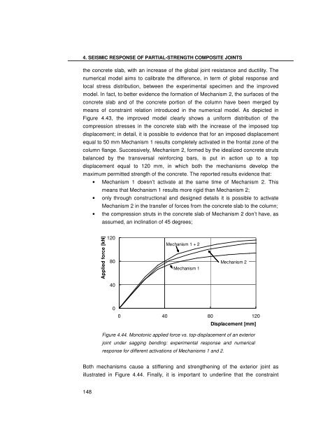
model. In fact, to better evidence <strong>the</strong> formation <strong>of</strong> Mechanism 2, <strong>the</strong> surfaces <strong>of</strong> <strong>the</strong><br />
concrete slab <strong>and</strong> <strong>of</strong> <strong>the</strong> concrete portion <strong>of</strong> <strong>the</strong> column have been merged by<br />
means <strong>of</strong> constraint relation introduced in <strong>the</strong> numerical model. As depicted in<br />
Figure 4.43, <strong>the</strong> improved model clearly shows a uniform distribution <strong>of</strong> <strong>the</strong><br />
compression stresses in <strong>the</strong> concrete slab with <strong>the</strong> increase <strong>of</strong> <strong>the</strong> imposed top<br />
displacement; in detail, it is possible to evidence that for an imposed displacement<br />
equal to 50 mm Mechanism 1 results completely activated in <strong>the</strong> frontal zone <strong>of</strong> <strong>the</strong><br />
column flange. Successively, Mechanism 2, formed by <strong>the</strong> idealized concrete struts<br />
balanced by <strong>the</strong> transversal reinforcing bars, is put in action up to a top<br />
displacement equal to 120 mm, in which both <strong>the</strong> mechanisms develop <strong>the</strong><br />
maximum permitted strength <strong>of</strong> <strong>the</strong> concrete. The reported results evidence that:<br />
148<br />
• Mechanism 1 doesn’t activate at <strong>the</strong> same time <strong>of</strong> Mechanism 2. This<br />
means that Mechanism 1 results more rigid than Mechanism 2;<br />
• only through constructional <strong>and</strong> designed details it is possible to activate<br />
Mechanism 2 in <strong>the</strong> transfer <strong>of</strong> forces from <strong>the</strong> concrete slab to <strong>the</strong> column;<br />
• <strong>the</strong> compression struts in <strong>the</strong> concrete slab <strong>of</strong> Mechanism 2 don’t have, as<br />
assumed, an inclination <strong>of</strong> 45 degrees;<br />
Applied force [kN]<br />
120<br />
80<br />
40<br />
0<br />
Mechanism 1 + 2<br />
Mechanism 1<br />
Mechanism 2<br />
0 40 80 120<br />
Displacement [mm]<br />
Figure 4.44. Monotonic applied force vs. top-displacement <strong>of</strong> an exterior<br />
joint under sagging bending: experimental response <strong>and</strong> numerical<br />
response for different activations <strong>of</strong> Mechanisms 1 <strong>and</strong> 2.<br />
Both mechanisms cause a stiffening <strong>and</strong> streng<strong>the</strong>ning <strong>of</strong> <strong>the</strong> exterior joint as<br />
illustrated in Figure 4.44. Finally, it is important to underline that <strong>the</strong> constraint


