Stimulators, Isolators
Stimulators, Isolators
Stimulators, Isolators

You also want an ePaper? Increase the reach of your titles
YUMPU automatically turns print PDFs into web optimized ePapers that Google loves.
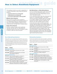
<strong>Stimulators</strong>, <strong>Isolators</strong><br />
DLS100<br />
A320<br />
A360LA<br />
A365<br />
A385<br />
A395<br />
DUO 773<br />
Feature Input Output Compatible Stimulator:<br />
Biphasic,<br />
Digital Analog<br />
Modeling<br />
SIU/built-in<br />
stimulator<br />
Digital from<br />
DS8000<br />
0-100 V<br />
1 A to 10 mA<br />
TTL 0-100 V<br />
1 A to 10 mA<br />
Monopolar TTL 0-100 V<br />
1 A to 10 mA<br />
Mono/Biphasic TTL ±100 V<br />
1 A to 10 mA<br />
High Current TTL ±36 V<br />
10 A to 100 mA<br />
Analog Analog<br />
±10 volts<br />
Intracellular<br />
Amplifier<br />
Analog<br />
0-1 volt<br />
±70 V<br />
1 A to 10 mA<br />
±500 nA<br />
DS8000<br />
DS8000<br />
DS8000<br />
DS8000<br />
DS8000<br />
DS8000<br />
DS8000<br />
Prices shown are in U.S. dollars. Actual charges will vary because of import duty, freight, and currency fluctuations. To obtain an exact quotation, contact your WPI office.<br />
World Precision Instruments Tel: Fax: E-mail: Internet: www.wpiinc.com<br />
A300<br />
A300<br />
A300<br />
A300<br />
A300<br />
A300<br />
A310<br />
A310<br />
A310<br />
A310<br />
A310<br />
A310<br />
23<br />
STIMULATORS, ISOLATORS
STIMULATORS, ISOLATORS<br />
DS8000 8-Channel Digital Stimulator<br />
Single board computer w/ LCD touch screen<br />
Scope mode displays waveforms<br />
8 banks of 3 timers, synchronous / asynchronous<br />
8 internal and 8 external trigger inputs<br />
32 separate outputs ( 24 BNC's front panel )<br />
The DS8000 represents a quantum leap in the performance of the<br />
research stimulator, and is the most advanced stimulator on the<br />
market. With a built-in computer, the entire waveform is generated<br />
digitally with precision timing. The DS8000 can generate stimulating<br />
wave patterns of a complexity unmatched by any other instrument<br />
on the market. A built in digital oscilloscope allows the user to<br />
preview waveforms on the LCD. An Ethernet connection allows the<br />
user to transfer custom waveforms and upgrade the software using<br />
TCP/IP protocol via remote access.<br />
The DS8000 has 8 analog outputs, 8 TTL outputs and 8 combined<br />
analog or TTL outputs. Each combined output can be comprised of<br />
a combination of any of 1 to 8 channels. Eight independent internal<br />
timers and eight independent external triggers are offered. The<br />
built-in waveforms include unipolar, bipolar, and paired pulse, as well<br />
as step, sine, ramp and custom. An external trigger, internal analog<br />
channel, internal TTL channel, or any of the eight built-in timers can<br />
be assigned to control each output channel.<br />
A unique feature of the DS8000 is the capability to stimulate with<br />
a waveform that is identical or similar to real biopotential wave<br />
patterns associated with ECG, EEG or action potentials. A biopotential<br />
waveform captured by a data acquisition system may be transferred<br />
to an Excel spreadsheet for editing or modification, then loaded into<br />
to the DS8000.<br />
One of the main problems of designing a stimulator is that a user<br />
might want very different stimulating patterns for different research<br />
applications. In order to satisfy all of these needs, traditional logical<br />
circuit based stimulators have control panels that use buttons<br />
and knobs to give the user as much control options as possible.<br />
However, even with a full panel of buttons, the selection of the<br />
stimulating pattern is still very limited. These types of stimulators<br />
can not generate complicated waveforms, such as combination<br />
pulses at varying interpulse intervals and amplitudes. Although<br />
microprocessor-based stimulators have made a significant step<br />
in solving these problems, certain complex waveforms are still<br />
Lifetime firmware upgrades via serial / Ethernet<br />
Unipolar, bipolar, paired pulse, sine, ramp, custom<br />
Custom upload of real biopotentials<br />
2 independent full parameter memory banks<br />
GLP / GCP compliant w / password protection<br />
impossible to generate. In fact, this decade old technology has<br />
serious limitations since each control button has been programmed<br />
to perform multiple functions. Moreover, it can only display limited<br />
lines of scrolled text—no graphics! To complicate matters, it is<br />
almost impossible to upgrade the software with new functions once<br />
the instrument has been manufactured; even the programming is<br />
awkward.<br />
The DS8000 overcomes the hardware limitations of other types of<br />
stimulators by being reliant on a flexible software-timing interface.<br />
The user can then apply this dynamically to almost any kind of<br />
stimulation protocol without being restricted by the hardware<br />
limitations of the traditional logical circuit based stimulators. In order<br />
to suit complex custom protocols, the DS8000 is designed to offer a<br />
unique flexibility by simply reprogramming the pattern output using<br />
a few keystrokes under pull-down menus.<br />
Although it may be argued that some functions of the DS8000 can<br />
be implemented on a standard PC, it is important to recognize that<br />
the inherent design of a PC operating system makes the accurate<br />
delivery of precision pulse protocols impossible. Despite the fact that<br />
PCs are very economical, they are simply not designed to generate<br />
highly accurate timing because the microprocessor resources are not<br />
prioritized for this function. In addition, analog waveform generation<br />
is not readily available without adding expensive output boards and<br />
the required programming is non-standard. The DS8000 platform is<br />
based on a powerful single board computer that is fully dedicated<br />
to the temporal accuracy and precision required in current biological<br />
and neurological research. Indeed, the DS8000 Digital Stimulator<br />
offers all of these solutions plus Good Laboratory Practices (GLP)<br />
compliance for research traceability.<br />
DS8000 — there is no competition!<br />
DS8000 8-Channel Digital Stimulator<br />
Prices shown are in U.S. dollars. Actual charges will vary because of import duty, freight, and currency fluctuations. To obtain an exact quotation, contact your WPI office.<br />
24 UK: Tel: Germany: Tel: China: Tel:
A quantum leap in the performance of the research stimulator<br />
Fig. 1<br />
Channel Settings<br />
Paired Pulse Protocol<br />
The DS8000’s Paired Pulse function allows<br />
the user to generate triggered paired<br />
pulses (including refractory period) from a<br />
single channel without the use of a train<br />
function. WPI’s paired pulse algorithm<br />
simplifies the arduous repetitive task normally<br />
associated with manual resetting of interpulse<br />
intervals in refractory studies. Auto-increment<br />
eliminates the need to overlap train functions<br />
from multiple channels to generate a complete<br />
protocol. Thus, there is a significant reduction in<br />
setup time and a minimization of the potential<br />
for human error during interactive protocol<br />
modification.<br />
Fig. 1 shows Channel 1 configured in<br />
the TRIGGERED PAIRED PULSE mode.<br />
In this example, a dual pulse event<br />
occurs synchronously with each trigger pulse<br />
from Channel 8, which is set to trigger every<br />
300 ms. The initial interpulse interval is set<br />
to 20 ms. Subsequent interpulse intervals<br />
are automatically incremented by 35 ms for<br />
each three consecutive paired pulse events.<br />
The resulting paired pulse is displayed in the<br />
lower trace on the DS8000 scope (Fig. 2). The<br />
upper trace shows the master trigger pulse set<br />
up on Channel 8.<br />
TIMING PARAMETERS<br />
PERIOD (TOTAL SIGNAL WIDTH) <br />
PULSE WIDTH <br />
BIPOLAR GAP WIDTH <br />
OPERATING MODES <br />
TRIGGERS <br />
<br />
TRAIN EVENTS 1-199<br />
TRAIN PULSE WIDTH <br />
TRAIN PULSE DELAY <br />
TRAIN PERIOD <br />
<br />
WAVEFORMS <br />
<br />
<br />
<br />
VARIABLE STEP WAVEFORM <br />
Soft Keys and GUI interface<br />
The DS8000 employs “soft keys”, which are<br />
programmable controls widely used in several<br />
menu options to sequentially change the<br />
numerical value of any variable waveform<br />
parameter. The DS8000’s soft keys are easily<br />
recognized as single or double “+” and “-“ signs<br />
located adjacent to a parameter value box (Fig.<br />
1). Soft keys provide quick and easy access to<br />
modify parameter values on the fly during an<br />
experiment. The GUI interface (Fig. 3) enables<br />
the user to assign the incremental value of the<br />
soft key to suit the needs of the experiment.<br />
Alternatively, a pop-up numeric keypad is<br />
accessible for each parameter to program<br />
a precise value that is not a multiple of the<br />
softkey-preset increment.<br />
Fig. 2<br />
Scope Display<br />
Combined Channel Assignment matrices<br />
The CTTL (COMBINED TTL matrix) and CA<br />
(COMBINED ANALOG matrix) screens permit<br />
the assignment of any combination of the<br />
8 available TTL or Analog signals to any<br />
permutation of the respective (8) CTTL or (8)<br />
DS8000 SPECIFICATIONS<br />
Fig. 3<br />
Graphic User Interface<br />
CA BNC outputs. The setup in Fig. 4 indicates<br />
that all TTL channels are assigned to their<br />
respective CTTL outputs with the exception<br />
of the output of CTTL 1, which is assigned a<br />
combination of the TTL signals from channels<br />
4 and 5. Changing assignments is as easy<br />
as checking the associated box. The CA tab<br />
reveals an identical matrix for programming<br />
the COMBINED ANALOG BNC outputs.<br />
Fig. 4<br />
Combined TTL Matrix<br />
OUTPUT NOISE <br />
<br />
OUTPUT VOLTAGE RESOLUTION <br />
<br />
<br />
<br />
<br />
<br />
<br />
MAINS VOLTAGE <br />
DIMENSIONS <br />
<br />
SHIPPING WEIGHT <br />
AMBIENT TEMPERATURE <br />
HUMIDITY <br />
SPECIFICATIONS SUBJECT TO CHANGE WITHOUT NOTICE.<br />
Prices shown are in U.S. dollars. Actual charges will vary because of import duty, freight, and currency fluctuations. To obtain an exact quotation, contact your WPI office.<br />
World Precision Instruments Tel: Fax: E-mail: Internet: www.wpiinc.com<br />
25<br />
STIMULATORS, ISOLATORS
STIMULATORS, ISOLATORS<br />
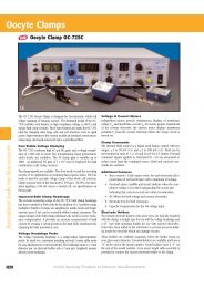
A300 Pulsemaster <br />
Multi-Channel Stimulator<br />
An integrated five-channel pulse generator/stimulator including<br />
one interval generator, five pulse or train channels, two mixer channels and one<br />
very quiet variable voltage output stage<br />
The Pulsemaster (Model A300) is WPI’s third generation,<br />
multichannel, pulse/train generator/stimulator that combines the<br />
superb accuracy of digital electronics with the “you-see-what-you-get”<br />
displays only available on single-channel products. In one compact<br />
rack mountable enclosure, the Pulsemaster contains an event interval<br />
generator, five pulse train channels, two mixing channels and a very<br />
quiet variable voltage output channel. System timing is accurate to<br />
100 ppm; output timing is continuously variable in 0.1% of full scale<br />
increments over a range of eight orders of magnitude. Bright, threedigit<br />
LED displays continuously and simultaneously show all the<br />
variable timing parameters.<br />
The Pulsemaster is designed for ease of use and flexibility. Each<br />
channel can be operated synchronized with the onboard event<br />
interval generator, triggered manually from any other channel<br />
or external source, and as an independent asynchronous pulse<br />
generator. Except for the external source, all channel interconnections<br />
are accomplished on the panel, without the use of cables. The<br />
output from each channel is compatible with standard digital circuitry<br />
and is also designed to drive WPI’s A300 series stimulus isolators.<br />
If desired, any channel’s output may be internally connected to the<br />
variable channel, whose amplitude can be continuously adjusted<br />
from millivolts to ten volts.<br />
The Event Interval<br />
The EVENT INTERVAL is the heartbeat of the Pulsemaster. Based on<br />
a highly accurate and stable crystal oscillator, the EVENT INTERVAL<br />
generates synchronization pulses at regular intervals. The width of<br />
the sync pulses is fixed at approximately 6 μs, but their repetition<br />
interval is panel adjustable from 10 μs to 999 s, using the display<br />
and its associated switches. Sync pulses may also be generated at<br />
random or irregular intervals by using the SINGLE EVENT or the<br />
EXTernal SYNC mode. The sync pulses are internally distributed to<br />
the five PULSE TRAIN channels and are also available externally<br />
through the SYNC OUT connector.<br />
The Pulse Train<br />
There are five PULSE TRAIN channels in the Pulsemaster. Except for<br />
sharing a common power supply, each is an independent instrument.<br />
Each channel has two adjustable timing parameters, DELAY and<br />
WIDTH, which in combination with internal or external signals may<br />
be used to create a variety of pulse and train waveforms. DELAY<br />
and WIDTH parameters can be changed while the instrument is<br />
operating.<br />
The basic difference between PULSE and TRAIN modes is the<br />
number of pulses that can be generated per sync pulse. In PULSE<br />
mode, only one pulse is generated for each sync pulse. As the sync<br />
pulse is received from one of the selected input sources, the leading<br />
rising edge of the pulse is recognized and a DELAY time/pulse<br />
WIDTH pair is generated. In TRAIN mode, multiple pulses can be<br />
generated per sync pulse. As in PULSE mode, as the leading rising<br />
Prices shown are in U.S. dollars. Actual charges will vary because of import duty, freight, and currency fluctuations. To obtain an exact quotation, contact your WPI office.<br />
26 UK: Tel: Germany: Tel: China: Tel:
edge of the sync pulse is recognized, a pulse WIDTH/DELAY pair is<br />
generated. Pulses (WIDTH/DELAY pairs) are continuously produced<br />
as long as the sync pulse is still “high” at the conclusion of the<br />
DELAY time.<br />
By means of the INPUT SELECT switch, sync pulses can be<br />
received from an external source through the EXT SYNC connector,<br />
manually by the SINGLE switch, from any of the other PULSE TRAIN<br />
channels, or one of the MIXER channels. The channel may also be<br />
disabled by switching to one of the OFF positions.<br />
EXT SYNC position: permits control of the PULSE TRAIN channel by<br />
other instruments and computers.<br />
SELF SYNC position: the channel becomes a free running pulse generator.<br />
The symmetry of the waveform can be adjusted by varying<br />
the DELAY and/or the WIDTH times.<br />
SINGLE EVENT position: pulses are generated at your discretion.<br />
Every time the SINGLE button is pressed, one and only one DELAY/<br />
WIDTH sequence is generated.<br />
EI position: connects the output of the EVENT INTERVAL generator<br />
to the input of the PULSE TRAIN channel. For every output sync<br />
pulse from the EVENT INTERVAL generator, one DELAY/WIDTH pair<br />
is generated.<br />
PT positions (4): internally connect the outputs from the respective<br />
PULSE TRAIN channels to the input of this PULSE TRAIN channel. In<br />
the PULSE mode, for every OUTPUT pulse from the other selected<br />
PULSE TRAIN channel, one DELAY/WIDTH pair is generated from this<br />
channel. In the TRAIN mode, pulses are generated from this channel<br />
as long as the pulse from the other channel remains “high.”<br />
MIX positions (2): internally connect the outputs from the respective<br />
MIXER channels to the input of this PULSE TRAIN channel. In the<br />
PULSE mode, for every OUTPUT pulse from the MIXER channel, one<br />
DELAY/WIDTH pair is generated from this channel. In TRAIN mode,<br />
pulses are generated from this channel as long as the pulse from the<br />
MIXER channel remains “high.”<br />
OUTPUT connector: supplies the waveforms generated by the<br />
PULSE TRAIN channel. This OUTPUT is designed to drive WPI’s<br />
A300 series stimulus isolators. It is also useful for synchronizing<br />
other instruments (recorders, oscilloscopes, computers, etc.) with the<br />
pulses generated from the Pulsemaster.<br />
The Mixer<br />
The MIXER does what its name implies, it combines any or all of the<br />
outputs of the PULSE TRAIN channels with external signals into one<br />
waveform. It can also provide a continuous (DC ON) or momentary<br />
(DC MOM) “high” level signal. The Mixer OUTPUT connector supplies<br />
the combination waveforms generated by the MIXER channel<br />
to drive WPI’s A300 series stimulus isolators or to synchronize the<br />
operation of other instruments with the Pulsemaster.<br />
The Variable Channel<br />
The VARIABLE channel can replicate the OUTPUT waveforms from<br />
any of the PULSE TRAIN or MIXER channels at amplitudes that can<br />
be varied from millivolts to ten volts. The channel also provides a<br />
very low noise, adjustable DC voltage source: the DC mode which<br />
converts the VARIABLE channel into a constant voltage source. The<br />
OUTPUT connector supplies the amplitude modified waveform or the<br />
DC voltage level of the VARIABLE channel.<br />
SYS-A300 Pulsemaster Multi-Channel Stimulator<br />
Specify line voltage<br />
A300 PULSEMASTER SPECIFICATIONS<br />
EVENT INTERVAL CHANNEL<br />
Operating Modes EXTernal SYNC, SINGLE EVENT, CONTINUOUS ON<br />
Input EXT SYNC accepts 1μs pulses; TTL, CMOS,<br />
RS232C compatible<br />
Timing EVENT INTERVAL 10 μs to 999 s (100 kHz - 0.001 Hz),<br />
±0.1% of full scale, continuously variable in 0.1% of full<br />
scale increments, through three orders of magnitude, in<br />
six ranges<br />
Output SYNC OUT pulse of 6 μs, TTL, 5 V CMOS compatible<br />
PULSE TRAIN CHANNEL (5 provided)<br />
Operating Modes EXTernal SYNC, SELF SYNC, manual SINGLE event,<br />
sync from Event Interval, sync from any of other four<br />
Pulse Trains, sync from one of the MIXers, off,<br />
TRAIN/PULSE<br />
Input EXT SYNC accepts 1μs pulses; TTL, CMOS,<br />
RS232C compatible<br />
Timing DELAY and WIDTH 10 μs to 999 s, ±0.1% of full scale,<br />
continuously variable in 0.1% of full scale increments,<br />
through three orders of magnitude, in six ranges<br />
(.0005 Hz to 50 kHz in the SELF SYNC mode)<br />
Output OUTPUT PULSE/TRAIN of preset timing, TTL, 5 V<br />
CMOS compatible, 4 mA sink and source<br />
MIXER CHANNEL (2 provided)<br />
Inputs Any combination of an EXTernal pulse, the outputs of<br />
the five Pulse Train channels, and DC continuous ON/<br />
DC MOMentary EXT INPUT accepts 1μs pulses; TTL,<br />
CMOS, RS232C compatible<br />
Output OUTPUT, TTL, 5V CMOS compatible, 4 mA sink and<br />
source<br />
VARIABLE CHANNEL<br />
Inputs Output from any one PULSE TRAIN channel<br />
or one of the two MIXER channels or DC<br />
Output 0 to +1 V low range, 1 mV resolution<br />
0 to +10 V high range, 10 mV resolution<br />
5 mA max sink and source<br />
Output Impedance
STIMULATORS, ISOLATORS<br />
A310<br />
Accupulser <br />
Combining the accuracy of digital<br />
electronics with the convenience of<br />
analog controls<br />
A pulse generator/stimulator combining the reproducibility and accuracy<br />
of digital electronics with the fine resolution and continuous adjustment<br />
possible with analog circuitry. All timing parameters are entered with tenturn<br />
readable potentiometers and six-position range switches. Outputs are<br />
accurate to within 1% of the set value.<br />
Pulses can be created in continuous run, single-shot, or train/burst<br />
modes. Duration of the train/burst is easily controlled using the onboard<br />
envelope generator or by using either of two external gating inputs. Used<br />
in conjunction with the A360, A365, A385, or A395, bipolar pulses or<br />
trains may be easily produced. Output stimulus can be fed through the<br />
Duo 773 for iontophoresis. Footswitch allows hands-free operation.<br />
Three separate outputs are available on the front panel. A Monitor<br />
output provides 10-15 V signals (up to 50 mA) for viewing the output on<br />
an oscilloscope or for controlling other devices. The stimulator’s signal,<br />
simultaneously available at the Isolator output, is sufficient to drive any<br />
WPI A300 Series stimulus isolator (A360, A365, or A385) and is also TTL<br />
and CMOS compatible. The Variable output can provide signals varying<br />
between ±10 V with a resolution of 1 mV. Separate variable outputs are<br />
provided for positive and negative signals.<br />
SYS-A310 Accupulser Signal Generator<br />
Specify line voltage<br />
OPTIONAL ACCESSORIES<br />
3259 Footswitch for A310<br />
2933 Rack Mount Kit, 51 ⁄4 in. high<br />
Optional footswitch #3259<br />
Stimulus Isolator<br />
(A360)<br />
A310 ACCUPULSER SPECIFICATIONS<br />
TIMING PARAMETERS<br />
EVENT INTERVAL 100 μs to1000 s*<br />
EVENT DELAY 10 μs to 100 s *<br />
PULSE WIDTH 10 μs to 100 s *<br />
TRAIN DURATION (ENVELOPE) 100 μs to 1000 s*<br />
PULSE INTERVAL<br />
OUTPUTS<br />
20 μs to 100 s*<br />
SYNC 5 μs, TTL, and 5 V CMOS compatible,<br />
20 mA max.<br />
MONITOR 10-15 V, 50 mA max.<br />
ISOLATOR<br />
VARIABLE (Pos or Neg)<br />
TTL & 5 V CMOS compatible, 20mA max.<br />
PULSED/DC LOW RANGE HIGH RANGE<br />
Range 0 to ±1 V 0 to ±10 V<br />
Resolution<br />
NOISE<br />
1 mV 10 mV<br />
Pulsed at 100 kHz bandwidth
Digital<br />
Linear<br />
Stimulus<br />
Isolator<br />
for use with DS8000<br />
Digital Stimulator<br />
The new DLS100 is preferentially optimized for applications in which the<br />
DS8000 digital stimulator is used.<br />
DLS100 connects to the DS8000 via a flexible cable through which<br />
it receives power and stimulus signals in a digital format. Up to eight<br />
DLS100 isolators can be connected independently to one DS8000. Very<br />
high isolation is achieved through the use of optical coupling of the<br />
digital signal and a galvanically isolated DC power supply within the<br />
DLS100. Unlike some other multi-channel isolators, this digital isolator<br />
can be located at the site of the experiment, allowing the use of short<br />
connecting leads and thereby preserving high isolation and fast signal<br />
rise and fall times.<br />
The DLS100 operates in two modes: current source or voltage source.<br />
In the current source mode, the output current is proportional to the<br />
amplitude and polarity of the signal generated by the DS8000. In the<br />
voltage source mode, the output voltage is proportional to the amplitude<br />
and polarity of the signal generated by the DS8000. The DLS100 has<br />
user-selectable push-button switches that select different current or<br />
voltage ranges (the full-scale current from 1 μA to 10 mA, or the 10V<br />
and 100V full-scale, respectively). Three status indicators on the DLS100<br />
indicate power on, activity (presence of signal from DS8000) as well as<br />
an alarm (over-range condition) indicator. Over-range can occur when<br />
the resistance of the load (the experiment) is too high for the current or<br />
voltage that is demanded from the DLS100.<br />
Top View<br />
DLS100 SPECIFICATIONS<br />
CURENT SOURCE MODE<br />
Full-scale Current 10 mA, 1 mA, 100 μA, 10 μA, 1 μA, bipolar<br />
Compliance Voltage ± 100 volts<br />
Output Impedance Greater than 100 Megohms<br />
Zero-signal Leakage Less than 0.01% of full-scale range setting<br />
10 mV @ 100 V / 10,000 Ohms,<br />
10 mA Scale = < 1 μA Leakage<br />
Linearity Better than 0.05% of full-scale range setting<br />
Bandwidth<br />
VOLTAGE SOURCE MODE<br />
Range and load dependant: 20 kHz with<br />
10K load and 100 μA or above range.<br />
Full-scale Voltage ± 100 volts<br />
Maximum Current 10 mA<br />
Output Impedance Less than 1 ohm<br />
Zero-signal Offset Less than 1 mv<br />
Linearity Better than 0.05% of full-scale range setting<br />
Bandwidth<br />
ISOLATION<br />
50 kHz<br />
Resistance Greater than 1000 Megohms<br />
Capacitance Less than 10 pF, from output terminals to<br />
DS8000 and earth ground<br />
POWER REQUIREMENTS +12 volts and +5 volts, supplied by DS8000<br />
DIMENSIONS 14 x 9 x 3.5 cm (5.5 x 3.5 x 1.5 in.)<br />
OUTPUT TERMINALS Mini-banana jacks<br />
CONNECTING CABLE 150 cm (5 ft)<br />
DLS100 Digital Linear Stimulus Isolator<br />
501670 Adapter, Dual Mini-Banana-to-BNC(F)<br />
83016 Replacement Cable, DLS100-to-DS8000<br />
Prices shown are in U.S. dollars. Actual charges will vary because of import duty, freight, and currency fluctuations. To obtain an exact quotation, contact your WPI office.<br />
World Precision Instruments Tel: Fax: E-mail: Internet: www.wpiinc.com<br />
29<br />
STIMULATORS, ISOLATORS
STIMULATORS, ISOLATORS<br />
Isostim Stimulator/Isolator<br />
Combining the ease of use and accuracy of WPI’s 300 Series stimulators<br />
with the power output of a stimulus isolator<br />
Timing<br />
Pulse interval<br />
and width are set<br />
with single-turn<br />
continuously variable<br />
controls from 5 ms to 5.5 s in three ranges. Pulse width is<br />
continuously variable from 50 μs to 550 ms in four ranges.<br />
Modes of operation<br />
In FREE RUN, Isostim generates continuous square waves. In EXT GATE or<br />
EXT SYNC modes, externally applied pulses can generate trains or single<br />
events. Single pulses of finite duration can be produced using a push-button<br />
on the instrument’s front panel. EXT/DC mode converts Isostim to a passive<br />
stimulus isolator.<br />
Dual tone audible alarm<br />
A tone sounds when an open circuit is detected or when system compliance<br />
is reached. A second tone, which sounds when a signal is applied to the<br />
input, can only be heard if the batteries have sufficient charge to operate the<br />
isolator. A violation light advises when pulse width exceeds the interval.<br />
ISOSTIM SPECIFICATIONS<br />
TIMING PARAMETERS<br />
Interval 5 ms to 5.5 s continuously variable<br />
in three ranges (0.18 to 200 Hz)<br />
Pulse width<br />
INPUT<br />
50 μs to 550 ms continuously<br />
variable in four ranges<br />
External sync Accepts 1 μs minimum pulses<br />
External gate Accepts 1 μs pulse to continuous<br />
Ext. command voltage threshold<br />
OUTPUT<br />
2.5 V at 3.5 mA min., 8.5 V max.<br />
Waveform DC, pulse from internal timing or<br />
externally generated pulse<br />
Current ranges 0-1 mA, 0-10 mA<br />
Load voltage excursion (compliance) 100 V nom., 150 V max.<br />
Output polarity Reversible, manual switch<br />
Current rise time and delay 8 μs, typical (1 K load)<br />
Current fall time and delay 10 μs, typical (1 K load)<br />
Leakage resistance, output to ground 1012 Ohms<br />
Optocoupler<br />
POWER<br />
2500 V rated min. breakdown voltage<br />
Dry Cell (Version D) 16 alkaline 9V batteries included<br />
Rechargeable (Version R) 16 rechargeable NiMH 9V batteries incl<br />
DIMENSIONS 8.5 x 3.5 x 4.9 in (22 x 9 x 12 cm)<br />
SHIPPING WEIGHT 4 lb (1.8 kg)<br />
Current delivery<br />
Stimulus currents up to 10 mA can be set on the front panel with a control<br />
knob and a two-position range switch. Output current is load-independent.<br />
Power<br />
Isostim model A320D is powered by readily obtainable 9-volt alkaline<br />
batteries (included). Under average use these will last several months before<br />
replacement is required. The rechargeable A320R is supplied with a nickel<br />
metal hydride battery stack which provides 10-12 hours of operation before<br />
recharge is required. The A362 Battery Charger must be used with the<br />
A320R.<br />
A362 Battery Charger<br />
Required for A320R, A365R and A395R<br />
Recharges the high-voltage nickel-cadmium or NiMH battery stack in the<br />
A320R, A365R or A395R. LED lamp indicates charging status. Full charge<br />
overnight. Dimensions: 2.8 x 4.1 x 5 in. (7 x 10 x 13 cm). Shipping<br />
weight: 4 lb (1.8 kg).<br />
SYS-A362 Battery Charger for A320R, A365R, A395R<br />
A320RC A320R with Charger (A362)<br />
SYS-A320D Isostim Stimulator/Isolator<br />
SYS-A320R Isostim Stimulator/Isolator (rechargeable)<br />
Specify line voltage<br />
OPTIONAL ACCESSORIES<br />
DRL Dummy Load Resistor Kit (set of 3)<br />
13347 BNC-to-Double Banana Adapter<br />
Prices shown are in U.S. dollars. Actual charges will vary because of import duty, freight, and currency fluctuations. To obtain an exact quotation, contact your WPI office.<br />
30 UK: Tel: Germany: Tel: China: Tel:
Stimulus <strong>Isolators</strong> / Precision Current Sources<br />
A360LA<br />
Activated by conventional logic-level commands, Model A360LA can be<br />
gated by any pulse generator, stimulator, or computer output.<br />
Dual tone audible alarms — A tone sounds when an open electrode<br />
circuit is detected or when system compliance is reached. A second<br />
optional tone sounds when a signal is applied to the input. A test switch<br />
is also provided to check battery charge.<br />
Current delivery — Stimulus currents are set using a three-digit control<br />
knob and a three-position range switch. Output current tracks control<br />
settings to better than 1%. Output current is load independent; voltage<br />
sufficient to push the desired current through the load is automatically<br />
developed, subject only to compliance limits. Model A360LA produces<br />
up to 10 milliampere current, in three ranges, at more than 100 volts<br />
compliance.<br />
Polarity — Output polarity is determined by a three-position switch on<br />
the front panel (+/-/off).<br />
A360LA High Voltage Isolator, charger included<br />
Specify line voltage<br />
OPTIONAL ACCESSORIES<br />
DRL Dummy Load Resistor Kit (set of 3)<br />
13347 BNC-to-Double Banana Adapter<br />
A360LA SPECIFICATIONS<br />
OUTPUT WAVEFORM DC or current pulse<br />
OUTPUT CURRENT RANGES 0.1, 1.0, and 10 mA<br />
CURRENT AMPLITUDE ERROR 0.5% of full scale, max.<br />
CURRENT RESOLUTION<br />
OUTPUT LOAD VOLTAGE<br />
0.1% of full scale, typical<br />
EXCURSION (COMPLIANCE) 100 V minimum, 130 V nominal<br />
EXTERNAL COMMAND THRESHOLD 2.2 V at 2.6 mA, min. 8.5 V, max. (TTL)<br />
OUTPUT POLARITY Reversible, manual switch<br />
CURRENT RISE TIME & DELAY 2 μs, typical (1 K load) 5 μs @ 10 K<br />
CURRENT FALL TIME & DELAY 5 μs, typical (1 K load) 8 μs @ 10 K<br />
OUTPUT TO GROUND RESISTANCE 1012 OPTOCOUPLER 2500 V, rated min. breakdown voltage<br />
NOISE
STIMULATORS, ISOLATORS<br />
Combines optical isolation with a ±100 mA current generator<br />
A385 High<br />
Current Stimulus<br />
Isolator<br />
Delivers positive, negative, or bipolar currents. For bipolar delivery,<br />
polarity of the output is toggled to the opposite state with each pulse<br />
presented to the input. Pulse duration is controlled by an externally<br />
applied voltage. Input connector is a standard BNC, allowing signals from<br />
any source — such as computer D/A or I/O lines — to be used.<br />
Output amplitude is set on a 3-digit, ten-turn dial as a percentage of<br />
the range selected: for example, a setting of 45.6 in the 0-10 mA range<br />
translates to 4.56 mA at the output. Accuracy and repeatability are excellent.<br />
Designed for subcutaneous stimulation, maximum output voltage at<br />
the stimulating electrodes is 36 volts, reducing the possibility of serious<br />
accidental transcutaneous shocks. A compliance/output alarm sounds<br />
A385 SPECIFICATIONS<br />
OUTPUT WAVEFORM DC or current pulse<br />
OUTPUT CURRENT RANGES 1, 10, and 100 mA<br />
CURRENT AMPLITUDE ERROR<br />
CURRENT RESOLUTION<br />
0.5% of full scale, max<br />
REPEATABILITY<br />
OUTPUT LOAD VOLTAGE<br />
0.1% of full scale, typical<br />
EXCURSION (COMPLIANCE)<br />
EXTERNAL COMMAND VOLTAGE<br />
36 V<br />
THRESHOLD 2.2 V, min<br />
OUTPUT POLARITY Reversible, manual switch, or<br />
electronically switched bipolar delivery<br />
CURRENT RISE TIME AND DELAY 6 μs, typical (1 K load)<br />
CURRENT FALL TIME AND DELAY 10 μs, typical (1 Kload)<br />
OUTPUT TO GROUND RESISTANCE 1012 <br />
OPTOCOUPLER 2500 V, rated minimum breakdown<br />
voltage<br />
POWER Six rechargeable lead-acid batteries<br />
(Requires companion charger A382)<br />
DIMENSIONS 8.5 x 3.5 x 5 in. (22 x 9 x 12 cm)<br />
SHIPPING WEIGHT 5 lb (2.3 kg)<br />
when the 36-volt limit is reached. Internal circuitry maintains electrodes<br />
short-circuited during inactive periods (“electrode exhauster” feature).<br />
A385 is not appropriate for transcutaneous stimulation.<br />
The 1.2 amp-hour rating of the six heavy-duty lead-acid rechargeable<br />
batteries ensures that experiments will not be interrupted by dead batteries<br />
— even at peak currents. Indicator lights and audible alarms keep the<br />
user constantly apprised of battery charge status. These batteries must<br />
be recharged by the A382 System Charger designed especially for the<br />
A385.<br />
A385RC A385R with A382 Charger<br />
SYS-A385R High Current Isolator, rechargeable<br />
SYS-A382 Battery Charger for A385 (see below)<br />
Specify line voltage<br />
OPTIONAL ACCESSORIES<br />
3468 Dual Rack Mount Kit<br />
A382<br />
Battery<br />
Charger<br />
An innovative threestep<br />
charger, A382<br />
employs fast, medium, and<br />
trickle charges at a safe, low current, greatly extending battery life. After<br />
a fast initial phase, the charger automatically switches to a constant<br />
voltage mode. When charging is complete, the charger switches to the<br />
trickle-charge mode. LED lamps indicate charging status. (For use only in<br />
charging batteries installed in the A385.)<br />
A382 SPECIFICATIONS<br />
POWER 95-135 V or 220-240 V, 50/60 Hz<br />
DIMENSIONS 8.5 x 3.5 x 5 in (22 x 9 x 12 cm)<br />
SHIPPING WEIGHT 5 lb (2.3 kg)<br />
Prices shown are in U.S. dollars. Actual charges will vary because of import duty, freight, and currency fluctuations. To obtain an exact quotation, contact your WPI office.<br />
32 UK: Tel: Germany: Tel: China: Tel:
A395 Linear Stimulus Isolator<br />
Replicates a programmed waveform of any shape or polarity<br />
All WPI stimulus isolators are designed to supply constant current<br />
because current threshold (not voltage) is the most quantitatively<br />
reproducible parameter for stimulation of nerve and muscle. Model A395<br />
dispenses current reproducibly from its Output terminals; the amplitude<br />
being determined by the selected current RANGE and the input voltage.<br />
Current amplitude is “constant”, that is, load resistance independent,<br />
provided that the I x R (load) product does not exceed the available<br />
battery supply voltage. A visual indicator (the compliance LEDs) displays<br />
if I x R reaches this limit. When the unit is out of compliance, one of the<br />
two LEDs (labeled - and +) illuminate, depending in which direction the<br />
current is flowing. Model A395 D can generate a voltage of 70 volts or<br />
more across its OUTPUT terminals. Thus, the user can be sure that the<br />
amplitude of the current will be as dialed as long as the voltage drop<br />
across the load (stimulus electrode path) does not reach the magnitude<br />
of the supply voltage. The compliance LEDs will then be visible. The user<br />
would then know that (a) too much current was dialed for a given load<br />
or (b) inter-electrode resistance was too high or the electrode circuit path<br />
was open.<br />
Model A395 generates an output current of arbitrary (user-defined)<br />
wave shape; DC, AC, pulse, and combinations thereof. Battery operated,<br />
and photoelectrically-isolated from the input voltage drive, the instrument<br />
regenerates output currents which are linearly proportional to the analog<br />
voltage waveforms provided by your D/A converter or signal generator<br />
(see diagram below).<br />
The A395 is ideally suited for data acquisition and stimulator<br />
generators. It can be easily daisy-chained for mutiple channel<br />
requirements.<br />
INPUT<br />
OUTPUT<br />
Accepts<br />
analog<br />
input<br />
10 V<br />
0V<br />
-10 V<br />
+100 μA, +1 mA, +10 mA<br />
0<br />
-100 μA, -1 mA, -10 mA<br />
Current Delivery —A 10 V input<br />
produces the maximum output<br />
current for the current range<br />
selected, i.e., 100 μA, 1 mA,<br />
or 10 mA. Front panel controls<br />
allow DC current to be generated.<br />
Externally applied signals can be<br />
superimposed simultaneously (DC<br />
offset). Warning lamps indicate<br />
open circuit or excessive current<br />
conditions.<br />
Digital Meter — Measures DC or average output current.<br />
Overload Lamps — Indicate when output voltage has reached positive or<br />
negative compliance voltage limit.<br />
A395RC A395R with Charger (A362)<br />
SYS-A395D Linear Stimulus Isolator<br />
SYS-A395R Linear Stimulus Isolator, Rechargeable<br />
SYS-A362 Battery Charger<br />
Specify line voltage<br />
OPTIONAL ACCESSORIES<br />
3468 Dual Rack Mount Kit<br />
3469 Single Rack Mount Kit<br />
A395 SPECIFICATIONS<br />
OUTPUT CURRENT, Imax 3 ranges: 100μA, 1 mA, and 10 mA<br />
OUTPUT VOLTAGE RANGE ± 70 V<br />
OUTPUT BANDWIDTH 10 kHz (measured across 1K load R)<br />
INPUT RESISTANCE > 20 M<br />
INPUT VOLTAGE @ Imax ± 10 volts<br />
INPUT/OUTPUT LINEARITY ERROR < 0.5%<br />
RISE, FALL TIME<br />
POWER<br />
26 μs @ 10 K<br />
Model A395D 17 alkaline 9 V batteries<br />
Model A395R 17 rechargeable NiMH 9 V batteries<br />
DIMENSIONS 6.5 x 4 x 3.5 in. (16 x 10 x 9 cm)<br />
SHIPPING WEIGHT 4 lb (1.8 kg)<br />
A362 Battery Charger<br />
Required for A320R, A365R and A395R<br />
Recharges the high-voltage nickelcadmium<br />
or NiMH battery stack in<br />
the A320R, A365R or A395R. LED<br />
lamp indicates charging status. Full<br />
charge overnight.<br />
Dimensions: 2.8 x 4.1 x 5 in.<br />
(7 x 10.5 x 12.7 cm).<br />
Shipping weight: 4 lb (1.8 kg).<br />
Prices shown are in U.S. dollars. Actual charges will vary because of import duty, freight, and currency fluctuations. To obtain an exact quotation, contact your WPI office.<br />
World Precision Instruments Tel: Fax: E-mail: Internet: www.wpiinc.com<br />
33<br />
STIMULATORS, ISOLATORS
STIMULATORS, ISOLATORS<br />
Concentric Electrodes*<br />
Item Metal Core Length Imp Probe Outer Tip Core diam. Y dim. X dim. w/ polyimide Price<br />
Diameter (total) Diam. (pkg of 5)<br />
TM33CCNON US$ 265<br />
TM33CCINS US$ 288<br />
TM53CCINS US$ 322<br />
PTM23CC001NON US$ 380<br />
PTM3CC02INS US$ 403<br />
*All have a stainless steel outer shaft<br />
Concentric Bipolar Electrodes<br />
Excellent for shielded macro recording as well as evoked<br />
potentials — especially well suited for bipolar stimulation<br />
The tungsten electrode is sharpened to a point and is 75 microns in<br />
diameter. The outer stainless steel conductor is insulated with Polyimide<br />
tubing to within 0.2 mm of the end of the stainless steel tube. Also<br />
available without the outer Polyimide insulation.<br />
See detailed metal microelectrodes on<br />
pages 18-19<br />
shrink tubing<br />
exposed stainless steel surface<br />
stainless steel tubing Polyimide tubing<br />
L=3" or 5" (2" for PTM)<br />
core conductor<br />
Prices shown are in U.S. dollars. Actual charges will vary because of import duty, freight, and currency fluctuations. To obtain an exact quotation, contact your WPI office.<br />
34 UK: Tel: Germany: Tel: China: Tel: <br />
Y
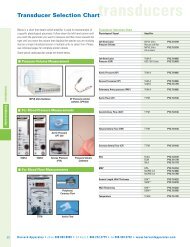
Blood Pressure Monitor and Transducer<br />
BP1 SPECIFICATIONS<br />
AMPLIFICATION x1, x10, x100, variable (x5 to x1000)<br />
BANDWIDTH, SMALL SIGNAL (-3 dB) 300 kHz (x1)<br />
30 kHz (x10)<br />
3 kHz (x100)<br />
0.3 kHz (x1000)<br />
OUTPUT VOLTAGE SWING ± 5 volts<br />
MAXIMUM OUTPUT CURRENT 2 mA<br />
INPUT IMPEDANCE, EACH INPUT 100 k || 0.01 μF<br />
TRANSDUCER APPLIED VOLTS 10 V nominal, varies with load. 25<br />
mA, maximum<br />
DIGITAL PANEL METER 0 to 1999 mV (calibrated in mm of Hg<br />
pressure when supplied with pressure<br />
gauge). Meter reads average value or<br />
± peak (1 to 20 Hz).<br />
POWER 95-135 V or 220-240 V, 50/60 Hz<br />
DIMENSIONS 8.5x5.12x10 in. (21.6x13x25.44 cm)<br />
SHIPPING WEIGHT 11 lb (5 kg)<br />
BLPR2 SPECIFICATIONS<br />
WORKING PRESSURE -50 to + 300 mm Hg<br />
OVERPRESSURE -400 to +4000 mm Hg<br />
EXCITATION VOLTAGE 1-10 VDC or RMS to 5 kHz<br />
INPUT IMPEDANCE 350 ±10%<br />
OUTPUT IMPEDANCE 300 ±10%<br />
ISOLATION < 5 μA leakage at 120 VAC<br />
SENSITIVITY 5 μV/V/mm Hg<br />
DYNAMIC RESPONSE 100 Hz<br />
EIGHT HOUR DRIFT 1 mm Hg after 5 minute warm-up<br />
MAXIMUM ERROR Total combined effects of Sensitivity, Linearity,<br />
Hysteresis (at 25°C and 5 μV/V/mm Hg) do not<br />
exceed ±2% or 1 mm Hg, whichever is greater.<br />
ENVIRONMENTAL<br />
Operating Temp. Range +15°C to +40°C<br />
Storage Temp. Range -30°C to +60°C<br />
Light Sensitivity Not affected by light under 3000 ft/candles<br />
(32,000 lux)<br />
SHIPPING WEIGHT 1 lb<br />
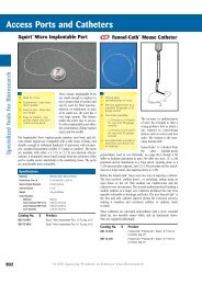
Monitors pressure, force, temperature<br />
Monitors animal arterial or venous blood pressure<br />
Displays systolic, diastolic or average blood pressure<br />
BP1 accepts WPI’s BLPR blood pressure transducer (below) as well as other<br />
blood pressure transducers.<br />
An audio monitor provides a signal with variable pitch and amplitude,<br />
allowing you to hear changes in blood pressure. Digital LCD display provides<br />
average or peak signal values from 0 to 1999 mV. With an optional pressure<br />
gauge (not provided — see PM015D/R, page 235), the user may calibrate the<br />
display to read mm Hg. Recorder output connector allows direct connection to<br />
a pen recorder, oscilloscope or computer via a data acquisition system.<br />
SYS-BP1<br />
ACCESSORIES<br />
Pressure Monitor (transducer & cable not included)<br />
Specify line voltage<br />
BLPR2 NEW Blood Pressure Transducer & Cable<br />
BPCABLE2 NEW Cable (12 ft) with DIN connector for BLPR2<br />
503067 BLPR2 Transducer without cable<br />
13024 Single Rack Mount Kit<br />
13025 Dual Rack Mount Kit<br />
3491 Extension Cable, 5 ft<br />
500184 BNC-to-BNC Cable, 10 ft<br />
14036-15 4-Way Luer Stopcock, Blue Tint (package of 15)<br />
KZ1101 Micro Cannula, 3 inch<br />
Note: BLPR2 is intended for animal research only and may not be<br />
used for human blood pressure measurement.<br />
BLOOD PRESSURE<br />
TRANSDUCER<br />
Stopcock #14036<br />
included with BLPR2<br />
BLPR2 can be used for the direct arterial and venous pressure measurement<br />
in animal blood vessels. Supplied sterile, BLPR2 is accurate,<br />
linear and stable with temperature. May be sterilized cold with Cidex or a<br />
similar bactericide.<br />
BLPR2 is equipped with a twelve-foot cable and connector compatible<br />
with WPI’s four-channel signal conditioning unit, TBM4M Transbridge,<br />
and the single-channel BP1 blood pressure monitor. Cable has moistureresistant<br />
locking connector. A continuous, uniform lumen eliminates<br />
places for bubbles to form and lodge. The clear fluid path is easy to<br />
inspect. Easy to mount — slotted transducer body accepts Velcro strap.<br />
To facilitate setup and operation, a four-way stopcock that allows easy<br />
filling, flushing, and zeroing of the transducer is included. Typically, the<br />
stopcock is located between the transducer and the animal catheter<br />
where it can be used to quickly zero, flush, or de-bubble the transducer.<br />
Prices shown are in U.S. dollars. Actual charges will vary because of import duty, freight, and currency fluctuations. To obtain an exact quotation, contact your WPI office.<br />
World Precision Instruments Tel: Fax: E-mail: Internet: www.wpiinc.com<br />
35<br />
PHYSIOLOGY