ENGINEERING DRAWING
ENGINEERING DRAWING ENGINEERING DRAWING
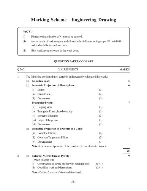
Marking Scheme—Engineering Drawing NOTE : (i) Dimensioning mistakes of ±1 mm to be ignored. (ii) Arrow heads of various types and all methods of dimensioning as per SP : 46-1988 codes should be treated as correct. (iii) Give marks proportionate to the work done. QUESTION PAPER CODE 68/1 Q.NO. VALUE POINTS MARKS 1. The following portions drawn correctly and accurately with good line work : (a) Isometric scale 5 (b) Isometric Projection of Hemisphere : 6 (i) Ellipse (3) (ii) Semi-Circle (2) (iii) Dimensions (1) Triangular Prism : 7 (iv) Helping View (1) (v) Triangular Prism placed centrally (1) (vi) Isometric Triangles (3) (vii) Edges of the prism (1) (viii) Dimensions (1) (c) Isometric Projection of Frustum of a Cone : 7 (ii) Isometric Ellipses (4) (iii) Common Tangents to Ellipes (2) (iv) Dimensioning (1) Note : For incorrect position of the frustum of cone deduct (1) mark. 25 2. (a) External Metric Thread Profile : (Drawn to scale 1:1) 9 (i) Construction of thread profile with hatching lines (5+1) (ii) Good line work and dimensions (2+1) Note : Deduct 2 marks if sketched free-hand. 321
Q.NO. VALUE POINTS MARKS (OR) Hexagonal Nut (Drawn to scale 1:1) (i) Front View (2½) (ii) Top View (2½) (iii) Side View (1) (iv) Good line work and dimensioning (2+1) Note : Deduct 2 marks if sketched free-hand. (b) The following portions sketched free-hand and drawn proportionately : 6 COUNTER SUNK HEAD RIVET : (i) Front view (4) (ii) Top view (1) (iii) Dimensions (1) Note : Deduct 1 mark, if drawn to scale. OR COLLAR-STUD : (i) Front view (4) (ii) Side view (1) (iii) Dimensions (1) Note : Deduct 1 mark, if drawn to scale. 3. SOCKET AND SPIGOT JOINT The following portions drawn correctly and accurately : (a) FRONT VIEW (Upper half in Section) 15 (i) Socket : Upper half in Section. (4) (ii) Socket : Lower half w/o Section. (3) (iii) Spigot: Upper half in Section (4) (iv) Spigot: Lower half w/o Section (2) (v) Cotter: Having one side taper (2) (b) SIDE VIEW (R.H.S.) 8 (i) For Socket and Spigot (6) (ii) Cotter (2) 322 15
- Page 1 and 2: ENGINEERING DRAWING Time allowed :
- Page 3 and 4: QUESTION PAPER CODE 68 1. (a) Const
- Page 5: OR Fig. 2 shows the details of the
- Page 9 and 10: 324
- Page 11 and 12: 326
- Page 13 and 14: 328
- Page 15 and 16: Q.NO. VALUE POINTS MARKS (b) The fo
- Page 17 and 18: 332
- Page 19 and 20: 334
- Page 21: 336
Marking Scheme—Engineering Drawing<br />
NOTE :<br />
(i) Dimensioning mistakes of ±1 mm to be ignored.<br />
(ii) Arrow heads of various types and all methods of dimensioning as per SP : 46-1988<br />
codes should be treated as correct.<br />
(iii) Give marks proportionate to the work done.<br />
QUESTION PAPER CODE 68/1<br />
Q.NO. VALUE POINTS MARKS<br />
1. The following portions drawn correctly and accurately with good line work :<br />
(a) Isometric scale 5<br />
(b) Isometric Projection of Hemisphere : 6<br />
(i) Ellipse (3)<br />
(ii) Semi-Circle (2)<br />
(iii) Dimensions (1)<br />
Triangular Prism : 7<br />
(iv) Helping View (1)<br />
(v) Triangular Prism placed centrally (1)<br />
(vi) Isometric Triangles (3)<br />
(vii) Edges of the prism (1)<br />
(viii) Dimensions (1)<br />
(c) Isometric Projection of Frustum of a Cone : 7<br />
(ii) Isometric Ellipses (4)<br />
(iii) Common Tangents to Ellipes (2)<br />
(iv) Dimensioning (1)<br />
Note : For incorrect position of the frustum of cone deduct (1) mark.<br />
25<br />
2. (a) External Metric Thread Profile :<br />
(Drawn to scale 1:1)<br />
9<br />
(i) Construction of thread profile with hatching lines (5+1)<br />
(ii) Good line work and dimensions (2+1)<br />
Note : Deduct 2 marks if sketched free-hand.<br />
321


