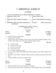
ENGINEERING DRAWING
ENGINEERING DRAWING
ENGINEERING DRAWING

Create successful ePaper yourself
Turn your PDF publications into a flip-book with our unique Google optimized e-Paper software.
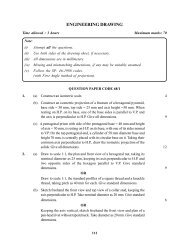
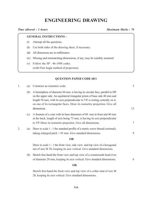
<strong>ENGINEERING</strong> <strong>DRAWING</strong><br />
Time allowed : 3 hours Maximum Marks : 70<br />
GENERAL INSTRUCTIONS :<br />
(i) Attempt all the questions.<br />
(ii) Use both sides of the drawing sheet, if necessary.<br />
(iii) All dimensons are in millimeters.<br />
(iv) Missing and mismatching dimensions, if any, may be suitably assumed.<br />
(v) Follow the SP : 46-1988 codes.<br />
(with First Angle method of projection).<br />
QUESTION PAPER CODE 68/1<br />
1. (a) Construct an isometric scale. 5<br />
(b) A hemisphere of diameter 84 mm, is having its circular face, parallel to HP<br />
on the upper side. An equilateral triangular prism of base side 40 mm and<br />
length 50 mm, with its axis perpendicular to VP, is resting centrally on it,<br />
on one of its rectangular faces. Draw its isometric projection. Give all<br />
dimensions. 13<br />
(c) A frustum of a cone with its base diameters of 60 mm in front and 40 mm<br />
at the back, length of axis being 75 mm, is having its axis perpendicular<br />
to VP. Draw its isometric projection. Give all dimensions. 7<br />
2. (a) Draw to scale 1 : 1 the standard profile of a metric screw thread (external),<br />
taking enlarged pitch = 45 mm. Give standard dimensions. 9<br />
OR<br />
Draw to scale 1 : 1 the front view, side view and top view of a hexagonal<br />
nut of size M 30, keeping its axis vertical. Give standard dimensions.<br />
(b) Sketch free-hand the front view and top view of a countersunk head rivet<br />
of diameter 20 mm, keeping its axis vertical. Give standard dimensions. 6<br />
OR<br />
Sketch free-hand the front view and top view of a collar stud of size M<br />
20, keeping its axis vertical. Give standard dimensions.<br />
316
3. Fig. 1 shows the details of the parts of a Socket and Spigot Joint. Assemble<br />
these parts correctly and then draw its following views to scale 1 : 1 :<br />
(a) Front view upper-half in section. 16<br />
(b) Side view, as viewed from right. 10<br />
Write heading and scale used. Draw projection symbol. Give six important<br />
dimensions. 4<br />
OR<br />
Fig. 2 shows the details of the parts of a Bush Bearing. Assemble these parts<br />
correctly and then draw its following views to scale 1 : 1 :<br />
(a) Front view, right-half in section. 16<br />
(b) Top view 10<br />
Write heading and scale used. Draw projection symol. Give six important dimensions. 4<br />
317
QUESTION PAPER CODE 68<br />
1. (a) Construct an isometric scale. 5<br />
(b) A hemisphere of diameter 84 mm is having its circular face parallel to HP<br />
on the upper side. A regular pentagonal prism of base side 24 mm and<br />
height 55 mm, is resting centrally on it, with a base side, away from the<br />
observer, parallel to VP and their common axis perpendicular to HP. Draw<br />
its isometric projection. Give all dimensions. 13<br />
(c) A frustum of a regular hexagonal pyramid, base side 28 mm, top side 16<br />
mm and height of frustum 60 mm, is having a base side parallel to VP and<br />
axis perpendicular to HP. Draw its isometric projection and give all<br />
dimensions. 7<br />
318
2. (a) Draw to scale 1 : 1 the standard profile of a metric screw thread (external),<br />
taking enlarged pitch = 50 mm. Give standard dimensions.<br />
OR<br />
Draw to scale 1 : 1 the front view and side view of a square headed bolt<br />
of size M24×3×110 mm long, fitted with a hexagonal nut. Keep their<br />
common axis parallel to HP and VP. Give standard dimensions.<br />
9<br />
(b) Sketch free-hand the front view of a round head machine screw of size<br />
M12, keeping its axis vertical. Give standard dimensions. 6<br />
OR<br />
Sketch free-hand the front view and top view of a flat head rivet of<br />
diameter 20 mm, keeping its axis vertical. Give standard dimensions.<br />
3. Fig. 1 shows the details of the parts of an Open Bearing. Assemble these parts<br />
correctly and then draw its following view to scale 1 : 1 :<br />
(a) Front view, right-half in section. 16<br />
(b) Top view 10<br />
(c) Side view as viewed from left. 6<br />
Write heading and scale used. Draw projection symbol. Give 6 important dimensions. 4<br />
319
OR<br />
Fig. 2 shows the details of the parts of a socket and spigot joint. Assemble<br />
these parts correctly and then draw its following views to scale 1 : 1 :<br />
(a) Front view full in section. 16<br />
(b) Side view, as viewed from right. 10<br />
Write heading and scale used. Draw projection symbol. Give 6 important dimensions. 4<br />
320
Marking Scheme—Engineering Drawing<br />
NOTE :<br />
(i) Dimensioning mistakes of ±1 mm to be ignored.<br />
(ii) Arrow heads of various types and all methods of dimensioning as per SP : 46-1988<br />
codes should be treated as correct.<br />
(iii) Give marks proportionate to the work done.<br />
QUESTION PAPER CODE 68/1<br />
Q.NO. VALUE POINTS MARKS<br />
1. The following portions drawn correctly and accurately with good line work :<br />
(a) Isometric scale 5<br />
(b) Isometric Projection of Hemisphere : 6<br />
(i) Ellipse (3)<br />
(ii) Semi-Circle (2)<br />
(iii) Dimensions (1)<br />
Triangular Prism : 7<br />
(iv) Helping View (1)<br />
(v) Triangular Prism placed centrally (1)<br />
(vi) Isometric Triangles (3)<br />
(vii) Edges of the prism (1)<br />
(viii) Dimensions (1)<br />
(c) Isometric Projection of Frustum of a Cone : 7<br />
(ii) Isometric Ellipses (4)<br />
(iii) Common Tangents to Ellipes (2)<br />
(iv) Dimensioning (1)<br />
Note : For incorrect position of the frustum of cone deduct (1) mark.<br />
25<br />
2. (a) External Metric Thread Profile :<br />
(Drawn to scale 1:1)<br />
9<br />
(i) Construction of thread profile with hatching lines (5+1)<br />
(ii) Good line work and dimensions (2+1)<br />
Note : Deduct 2 marks if sketched free-hand.<br />
321
Q.NO. VALUE POINTS MARKS<br />
(OR)<br />
Hexagonal Nut<br />
(Drawn to scale 1:1)<br />
(i) Front View (2½)<br />
(ii) Top View (2½)<br />
(iii) Side View (1)<br />
(iv) Good line work and dimensioning (2+1)<br />
Note : Deduct 2 marks if sketched free-hand.<br />
(b) The following portions sketched free-hand and drawn proportionately : 6<br />
COUNTER SUNK HEAD RIVET :<br />
(i) Front view (4)<br />
(ii) Top view (1)<br />
(iii) Dimensions (1)<br />
Note : Deduct 1 mark, if drawn to scale.<br />
OR<br />
COLLAR-STUD :<br />
(i) Front view (4)<br />
(ii) Side view (1)<br />
(iii) Dimensions (1)<br />
Note : Deduct 1 mark, if drawn to scale.<br />
3. SOCKET AND SPIGOT JOINT<br />
The following portions drawn correctly and accurately :<br />
(a) FRONT VIEW (Upper half in Section) 15<br />
(i) Socket : Upper half in Section. (4)<br />
(ii) Socket : Lower half w/o Section. (3)<br />
(iii) Spigot: Upper half in Section (4)<br />
(iv) Spigot: Lower half w/o Section (2)<br />
(v) Cotter: Having one side taper (2)<br />
(b) SIDE VIEW (R.H.S.) 8<br />
(i) For Socket and Spigot (6)<br />
(ii) Cotter (2)<br />
322<br />
15
Q.NO. VALUE POINTS MARKS<br />
(c) Heading (1), Scale used (1), Projection symbol (1), Dimensions (2)<br />
Line work in front view and side view (2) 7<br />
Note : (a) If front view is drawn full in section, then deduct 2 marks.<br />
(b) If side view is not drawn as per instruction deduct 1 mark.<br />
BUSHED BEARING :<br />
OR<br />
The following portions drawn correctly and accurately :<br />
(a) Front View Block /Body (with Oil Hole) 15<br />
(i) Right Half in Section (7)<br />
(ii) Left Half without Section (4)<br />
Bush (With Hole)<br />
(iii) Right — Half in Section (2)<br />
(iv) Left Half without Section (2)<br />
(b) TOP VIEW 8<br />
(i) Body (2+2)<br />
(ii) 2 Bolt Holes (2)<br />
(iii) Oil Hole (1)<br />
(iv) Bush (1)<br />
(c) Heading (1), Scale used (1), Projection symbol (1), Dimensions (2)<br />
Line work in front view and side view (2)<br />
Note : If front view is drawn full in section, then deduct 2 marks.<br />
323<br />
30<br />
30
324
325
326
327<br />
R
328
QUESTION PAPER CODE 68<br />
Q.NO. VALUE POINTS MARKS<br />
1. The following portions drawn correctly and accurately with good line work :<br />
(a) Isometric scale 5<br />
(b) Isometric projection of Pentagonal Prism on Hemisphere :<br />
Hemi Sphere :<br />
6<br />
(i) Ellipse (3)<br />
(ii) Semi-Circle (2)<br />
(iii) Dimensions (1)<br />
Note : For incorrect position of the hemi-sphere deduct (1) mark.<br />
Pentagonal Prism : 7<br />
(vi) Helping View (1)<br />
(v) Placed Centrally (1)<br />
(vi) Two Pentagons (3)<br />
(vii) Face Edges (1)<br />
(viii) Dimensions (1)<br />
(c) Isometric Projection of Frustum of Hexagonal Pyramid : 7<br />
(i) Helping View for 2 Hexagons (2)<br />
(ii) Isometric hexagons (3)<br />
(iii) Slant edges (1)<br />
(iv) Dimensions (1)<br />
Note : For incorrect positon of each solid deduct (1) mark.<br />
25<br />
2. (a) External Metric Thread Profile 9<br />
(Drawn to scale 1:1)<br />
(i) Construction of thread profile with hatching lines (5+1)<br />
(ii) Good line work and dimensioning (2+1)<br />
Note : Deduct 2 marks if sketched free-hand.<br />
OR<br />
Square Headed Bolt With Hexagonal Nut<br />
(Drawn to scale 1:1)<br />
(i) Front View<br />
(a) Square Head Bolt (2)<br />
(b) Hexagonal Nut (2)<br />
(ii) Side View (2)<br />
(iii) Good line work and dimensioning (2+1)<br />
Note : Deduct 2 marks if sketched free-hand.<br />
329
Q.NO. VALUE POINTS MARKS<br />
(b) The following portions sketched free-hand and drawn proportionately :<br />
Round Head Machine Screw : 6<br />
(i) Front view (5)<br />
(ii) Dimensions (1)<br />
Note : Deduct 1 mark, if drawn to scale.<br />
OR<br />
Flat Head Rivet :<br />
(i) Front view (4)<br />
(ii) Top view (1)<br />
(iii) dimensions (1)<br />
Note : Deduct 1 mark, if drawn to scale.<br />
3. OPEN BUSH BEARING :<br />
The following portions drawn correctly and accurately :<br />
(a) FRONT VIEW<br />
Body<br />
15<br />
(i) Right Half in Section (6)<br />
(ii) Left Half w/o Section (4)<br />
Open Bush<br />
(iii) Right — Half in Section (3)<br />
(iv) Left Half w/o Section (2)<br />
(b) TOP VIEW 8<br />
(i) Body (5)<br />
(ii) Bush (3)<br />
(d) Heading (1), Scale used (1), Projection Symbol (1), Diamension (2),<br />
Line work in F.V and S.V. (2) 7<br />
Note : If front view is drawn full in section, then deduct 2 marks.<br />
OR<br />
330<br />
15<br />
30
Q.NO. VALUE POINTS MARKS<br />
Socket and Spigot Joint :<br />
The following portions drawn correctly and accurately :<br />
(a) Front View (Full Section) 15<br />
(i) Socket: Full Section (7)<br />
(ii) Spigot: Full Section (6)<br />
(iii) Cotter: Having one side taper (2)<br />
(b) SIDE VIEW (R.H.S.) 8<br />
(i) For Socket and Spigot (6)<br />
(ii) Cotter (2)<br />
(c) Heading (1), Scale used (1), Projection Symbol (1), Dimension (2),<br />
Line work in F.V. and S.V. (2) 7<br />
Note:<br />
(a) If front view is drawn full in section, then deduct 2 marks.<br />
(b) If side view is not drawn as per instruction, deduct 1 mark.<br />
331<br />
30
332
333
334
335
336