pluton
pluton
pluton

You also want an ePaper? Increase the reach of your titles
YUMPU automatically turns print PDFs into web optimized ePapers that Google loves.
8.3 PLUTON - Graphics Menu WinGX v1.64<br />
Chapter 8.3 PLUTON<br />
Chapter 8.3<br />
P L U T O N<br />
This is a preliminary Introduction to<br />
the program. See the Platon website<br />
at<br />
http://www.cryst.chem.uu.nl/platon<br />
for up-to-date program information.<br />
A.L.SPEK,<br />
BIJVOET CENTER FOR BIOMOLECULAR RESEARCH,<br />
VAKGROEP KRISTAL- EN STRUCTUURCHEMIE,<br />
UNIVERSITY OF UTRECHT,<br />
PADUALAAN 8, 3584 CH UTRECHT,<br />
THE NETHERLANDS.<br />
1
8.3 PLUTON - Graphics Menu WinGX v1.64<br />
1-INTRODUCTION TO PLUTON..................................................................................................................... 3<br />
2-INTRODUCTORY EXAMPLE....................................................................................................................... 4<br />
3-HOW PLUTON WORKS ................................................................................................................................. 9<br />
3.1 TERMS AND NOTIONS. ................................................................................................................................. 10<br />
4-INSTRUCTION SUMMARY......................................................................................................................... 11<br />
APPENDIX - I : THE INPUT PARAMETER FILE....................................................................................... 27<br />
A1.1 CARD TYPES RELEVANT TO PLUTON ............................................................................................ 27<br />
A1.2 - THE SHELX STYLE FORMAT........................................................................................................... 28<br />
A1.3 - ANGSTROM DATA FORMAT ........................................................................................................... 28<br />
A1.4 - CIF-DATA FORMAT........................................................................................................................... 29<br />
APPENDIX - II : SPACE GROUP SYMMETRY.......................................................................................... 29<br />
Chapter 8.3 PLUTON<br />
2
8.3 PLUTON - Graphics Menu WinGX v1.64<br />
1-INTRODUCTION TO PLUTON<br />
PLUTON is an easy-to-use interactive graphics program. It can be used as a tool for viewing,<br />
analysis and presentation of molecular structures. Drawings of either individual molecules or<br />
assemblies of molecules in a crystalline arrangement can be produced. Coordinate input data<br />
can be either Carthesian or fractional, originating from crystal structure determination<br />
programs such as SHELXS-86 or refinement programs such as SHELXL-93.<br />
PLUTON may be considered as a completely redesigned and considerably expanded variety<br />
of the popular program PLUTO78 by Motherwell and Clegg. Drawings are produced either<br />
on a display surface (graphics terminal or workstation) called DISPLAY or as a meta-file<br />
saving graphics instructions (called META) for later use such inclusion in word processors<br />
(e.g. Word) or laser printer hardcopy, suitable for publication.<br />
A drawing of a molecular structure as generated by PLUTON may be thought of in three<br />
principle aspects: the content, the style and the viewpoint. The content of the drawing requires<br />
the definition of items such as ARU's (= asymmetric residue units, vide infra) making up the<br />
list of molecules and anions to be displayed, atoms within ARU's, connections between atoms<br />
(= bonds), labels, and unit cell representation. By default, connected and possibly symmetry<br />
expanded sets of atoms constituting molecules or ions will be assembled. The style of the<br />
drawing may be like a STICK model (atoms are points and bonds are single lines joining<br />
them), a SOLID ball-and-spoke, ball-and-STRAW or ball-and-ROD model, mainly differing<br />
in the default settings of the variable radii for atoms and bonds, or a space filling model with<br />
van der Waals radii assigned to each atom (also called CPK model). The atom types may be<br />
distinguished with various patterns in the black-and-white mode or colored to differentiate<br />
between the atom types. Drawings may be made in parallel projection, perspective, or stereopair<br />
perspective. By default, a STICK-style drawing will be generated. The view direction<br />
may be chosen with reference to molecular features such as lines and planes defined by<br />
atoms, or with reference to the unit cell or orthogonal axial systems. The view direction may<br />
be further modified by rotations, giving flexible control of the viewpoint. By default a<br />
minimum overlap view is choosen.<br />
All input to the program is free-format, using (sub)keywords and numerical data. The input to<br />
PLUTON is normally provided in two parts: a disk file, in general produced by a program or<br />
prepared with a text editor and containing the pertinent data on the structure at hand such as<br />
atomic coordinates, followed by interactive input of the instructions via the keyboard. In<br />
general, a small set of instructions in terms of global keywords with associated default<br />
parameter settings will suffice to produce a drawing for the set of supplied atomic<br />
coordinates. Alternatively, all input may be given on the disk file or interactively from the<br />
keyboard.<br />
More than one data set, separated by an ENDS card may be present on the disk file. This is a<br />
convenient feature for browsing the structures retrieved from the Cambridge Structural<br />
Database. In that case, an interactively supplied END statement will not stop program<br />
execution but load the next data set (use the instruction STOP for premature abortion).<br />
Facilities are available (the SAVE instruction) to run the same set of instructions on a file that<br />
contains more than one data set (e.g. a series of structures extracted from the Cambridge<br />
Structural Database).<br />
Chapter 8.3 PLUTON<br />
3
8.3 PLUTON - Graphics Menu WinGX v1.64<br />
Note: PLUTON is not a finished program. It is extended and improved constantly on the basis<br />
of the needs that arise as part of our research work, including many hundreds of crystal<br />
structure determinations (organic, organometallic and inorganic) carried out as part of a<br />
national crystallographic service. New features are planned. Therefore there may be some<br />
discrepancies between the actual program and this manual. It is advised to consult the on-line<br />
manual (available with the HELP ALL feature of the program)<br />
for the most current list of instructions. A more up-to-date reference manual is at the<br />
following Web-site<br />
Chapter 8.3 PLUTON<br />
http://www.cryst.chem.uu.nl/platon/pl010000.html<br />
2-INTRODUCTORY EXAMPLE<br />
The following example of the structure of CYTOSINE should provide a simple introduction<br />
to the use of the program and its potential. The structural parameters are assumed to reside on<br />
a disk file, named CYTO.SPF in this example, for which the contents are listed below (free<br />
format). This particular input format is convenient for viewing structures with parameters<br />
taken from a publication:<br />
TITL CYTOSINE (ANHYDROUS) ACTA CRYST. B29, 1234, 1973.<br />
CELL 13.044 9.495 3.814 90 90 90<br />
SPGR P212121<br />
N1 0.0222 0.0285 0.4410<br />
C2 -.0164 0.1561 0.3276<br />
O2 -.0998 0.1595 0.1710<br />
N3 0.0402 0.2745 0.3877<br />
C4 0.1308 0.2635 0.5492<br />
N4 0.1842 0.3828 0.5967<br />
C5 0.1705 0.1337 0.6674<br />
C6 0.1134 0.0187 0.6084<br />
H1 -.013 -.057 0.363<br />
H3 0.154 0.463 0.541<br />
H4 0.248 0.378 0.652<br />
H5 0.237 0.128 0.796<br />
H6 0.132 -.078 0.692<br />
PLUTON may be invoked for this data set with the command: PLUTON CYTO<br />
4
8.3 PLUTON - Graphics Menu WinGX v1.64<br />
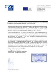
Figure 1<br />
As a result the data set CYTO is loaded and, since this file does not contain an END<br />
instruction at the end of the file, the program comes, after that the end-of-file has been<br />
reached on this file, with the prompt >>, ready to receive additional data and/or instructions<br />
interactively. When we now type in response to the prompt the instruction PLOT, the<br />
program will automatically assemble a unique molecule (i.e. symmetry operations will be<br />
applied when necessary to find connected sets of atoms), find all bonds and generate a<br />
minimum overlap stick-style plot of the structure (Fig. 1), optionally followed by a bell signal<br />
on completion of the plot. The program now waits for the user to press the RETURN (or<br />
ENTER) key to present the prompt >> again and to accept new instructions. Alternatively, a<br />
new instruction may be typed directly without waiting for the prompt. At this point the<br />
minimum overlap view direction may be modified with any of the available VIEW<br />
instructions. As an example we can rotate the structure clockwise by 45 degrees about the<br />
horizontal X-axis with the instruction VIEW CURRENT XROT 45 and see the effect with a<br />
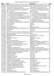
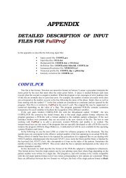
new PLOT instruction. The style of the plot may be changed into the SOLID, STRAW, ROD<br />
or CPK style with corresponding instructions:<br />
e.g. ROD SHADE followed by PLOT (Fig. 2) or CPK NET followed by PLOT (Fig. 3).<br />
Chapter 8.3 PLUTON<br />
5
8.3 PLUTON - Graphics Menu WinGX v1.64<br />
Chapter 8.3 PLUTON<br />
Figure 2<br />
A PLUTON session thus involves a series of cycles, each of which consisting of contents,<br />
style and viewpoint modification instructions, if any, followed by a PLOT instruction. As an<br />
aid, it is possible to inspect the contents of the various internal tables with instructions such as<br />
LIST ATOMS, LIST BONDS or LIST ARU. On-line information on the available<br />
instructions is available by typing HELP. A status line reports the current values on some of<br />
the more relevant settings. Use HELP GRAPHICS for instructions to<br />
change the default graphics settings.<br />
6
8.3 PLUTON - Graphics Menu WinGX v1.64<br />
Chapter 8.3 PLUTON<br />
Figure 3<br />
The input set of fractional coordinates is not required to form a connected set or even a<br />
complete molecule in case of molecules sitting on a crystallographic symmetry element.<br />
Unless instructed explicitly by the user, the necessarily calculations are carried out<br />
automatically as communicated to the user by the expression<br />
AEX:: JOIN RADII UNIQUE EXPAND.<br />
This will automatically generate a connected set based on standard covalent radii and<br />
symmetry expanded when applicable. Where appropriate the user is informed about problems,<br />
new parameter values and the current status of relevant parameters.<br />
Intermolecular hydrogen bonds of the type Donor-H...Acceptor may now be generated with<br />
the instruction:<br />
JOIN HBONDS<br />
An alternative would be<br />
JOIN RADII INTER H 1.2 O 1.5 N 1.5<br />
but this will generate many unwanted additional contacts that will have to be deleted<br />
subsequently from the bond list). The list options (e.g. LIST ATOM, LIST BONDS or LIST<br />
ARU) may be used following this instruction to verify that several items were added to the<br />
atom, bond and aru lists.<br />
7
8.3 PLUTON - Graphics Menu WinGX v1.64<br />
A SOLID type packing diagram with the unit cell outline and viewed down the c-axis of the<br />
structure is generated with a few additional instructions (Fig. 4):<br />
SOLID<br />
PACK RANGE -0.5 1.5 -0.5 1.5 0 1<br />
UNITCELL<br />
VIEW ZO<br />
PLOT<br />
Chapter 8.3 PLUTON<br />
Figure 4<br />
To finish the program the instruction END should be issued. The trailer listing file provides a<br />
detailed log of the current session. All instructions are saved on a journal file to reconstruct<br />
previous style and orientation settings. In addition the name of the generated meta file (if any)<br />
is given.<br />
8
8.3 PLUTON - Graphics Menu WinGX v1.64<br />
3-HOW PLUTON WORKS<br />
This section on program internals should provide a framework to understand most of the<br />
effects of the available instructions.<br />
The input atomic coordinates (x, y, z) are with reference to user-defined axes (a, b, c), which<br />
will usually be either crystallographic unit cell axes or an arbitrary orthogonal set; these<br />
coordinates are input as fractions of the unit cell edges or as Å units (in the latter case they are<br />
converted to and stored internally as fractions of dummy cell edges). A second, orthogonal<br />
system (A, B, C) (see J.D. Dunitz, X-Ray analysis and the Structure of Organic Molecules,<br />
Cornell University Press, p235) with coordinates (XO,YO,ZO) in Å is set up internally: The<br />
unit vector A is choosen along a, B as unit vector normal to a in the ab plane, and C normal to<br />
A and B. This orthogonal system is coincident with the first system when the input axes are<br />
orthogonal. The third system is the plotting coordinate system in cm: XP across the picture<br />
from left to right, YP up the picture from bottom to top and ZP out of the paper. All these<br />
axial sets are right-handed and absolute configuration is preserved in all rotations.<br />
As atoms are input to the program, they are stored both in the X, Y, Z and the XO, YO, ZO<br />
coordinate system. The XP, YP, ZP system is used only when plotting is actually being<br />
performed. Each atom has additional information stored for it including the atom name (the<br />
embedded element name is used by default to set various radii) and various flags such as for<br />
inclusion in the plot and labelling. This data structure is known as the atom list. Duplicate<br />
entries with the same coordinates are skipped from the input stream.<br />
The JOIN instructions (either by default or as specified) set up a list of connections (known as<br />
bond list) between atoms. Each connection is simply a pair of atom serial numbers referring<br />
to the input atom list. Some JOIN instructions also find connections between input atoms and<br />
other atoms related to the original list by crystallographic symmetry. This may include both<br />
connections to a symmetry related part of a molecule sitting on a special position or<br />
intermolecular connections. In order to store these connections for plotting, the program<br />
appends dummy symmetry-generated atoms to the atom list and marks them with a special<br />
flag.<br />
If the final picture is to contain several molecules, as in a packing diagram, or a complete<br />
molecule for which the input atoms represent only the symmetry-independent portion of it<br />
when a molecule lies in a crystallographically special position in the unit cell, the program<br />
will have to generate XP, YP, ZP coordinates for the atoms in each of these molecules or<br />
symmetry-related molecular fragments. This is controlled by two further lists: a list of<br />
symmetry operations pertaining to the structure, input directly using the SPGR or LATT and<br />
SYMM instructions; and a list of 'molecules and ions' (known as ARU list) to be drawn (see<br />
discussion on ARU & ASU below).<br />
The program works as follows. Instructions (free format) are read and interpreted. Various<br />
instructions add to the list of atoms and symmetry operators. The JOIN instructions set up the<br />
connections list and may also add to the atom and ARU-lists if connections between ARU's<br />
are to be generated. Plotting parameters are then set by user instructions or left at default<br />
settings. No plotting is actually done until the PLOT instruction is read. This first sets up the<br />
XP, YP, ZP plotting list of all atoms to be plotted. The information in the ARU list and the<br />
Chapter 8.3 PLUTON<br />
9
8.3 PLUTON - Graphics Menu WinGX v1.64<br />
current view matrix together tell the program how to convert X, Y, Z into XP, YP, ZP. The<br />
plotting coordinates and atom radii are scaled from Å to cm. and corrected for perspective if<br />
requested. In the non-stick mode, all atoms in the plotting list are drawn, allowing for<br />
obscuring of some by others and bonds, and intersection of spheres in space-filling models<br />
and bonds in the ROD mode, except that dummy atoms are not usually drawn - they are<br />
required only so that connections between molecules are possible, and will generally be<br />
duplicated by other non-dummy atoms generated in the XP, YP, ZP list by symmetry from the<br />
original input atoms. Following the atoms, all the bonds are drawn, omitting portions<br />
obscured by atoms or bonds. Atoms are labelled by a routine which minimises overlap of the<br />
labels by atoms, bonds and other labels. When the picture is complete, the next instruction<br />
may be read.<br />
Most data are stacked in a large array, either bottom-up or top down, so that the stack size is<br />
the limiting factor for the size of the problem that the program can handle. The program<br />
reports on the maximum memory usage in the current run. The stack size is a program<br />
implementation parameter. The input list of atoms is checked on redundancy.<br />
3.1 Terms and Notions.<br />
Connected sets of atoms are assembled in the following way. The procedure is started by first<br />
fixing a suitable atom. Next symmetry operations are performed on all atoms in the input set<br />
to find atoms that are connected to it. Atoms that are found to be connected are fixed as well<br />
and used to fix yet other, possibly symmetry transformed, atoms bonded to them as well. This<br />
procedure continues until no new bonded atoms are found. In the simple case of one chemical<br />
unit per asymmetric unit this constitutes an object named a molecule and is denoted with the<br />
identity code 1555. Symmetry related molecules are denoted by the general code sklm, where<br />
s is the number of the symmetry operation of the space group and k,l and m translation<br />
components. Chemical units may extend over more than one asymmetric unit. They may have<br />
a symmetry element that coincides with the space group symmetry such as an inversion centre<br />
or a screw axis. In such cases we will find atoms in the above search for a connected set of<br />
atoms that are bonded to the connected set at a position different from the one that was fixed<br />
in view of an earlier connection. Those atoms are added to the connected set and marked as<br />
symmetry related. The symmetry operation of this atom with respect to the primary one is<br />
coded and added to the molecule (aru) list. A chemical unit around an inversion centre thus<br />
consists in the PLUTO78 terminology of two molecules: 1555 and 2555. A further<br />
complication may be the presence of more than one crystallographically independent<br />
chemical unit in the unit cell (including solvent molecules and anions). In that case not all<br />
atoms will be fixed when the above procedure comes to an end when no more connected<br />
atoms are found. In that case a new residue is started by again arbitrarily fixing a suitable<br />
atom and expanding it to a connected set. A particular residue r within a molecule is indicated<br />
with the code sklm.r (e.g. 3564.03). It is understood that the code without a fraction stands for<br />
the full collection of residues. Thus in the case of two residues the molecule code 2562 is<br />
equivalent with the two residue codes 2562.01 and 2562.02. In order to be more precise two<br />
new terms have been introduced in PLUTON and PLATON. The basic structural unit is the<br />
asymmetric residue unit ( = aru ) coded as sklm.r. A molecule (ion) will will be an assembly<br />
of at least one aru. The set of aru's making up the asymmetric structural unit are called asu<br />
and encoded as sklm.<br />
Chapter 8.3 PLUTON<br />
10
8.3 PLUTON - Graphics Menu WinGX v1.64<br />
Disorder. Based on the supplied population parameters attemps are made to suppress bonds<br />
between disorder parts with unequal population parameter values.<br />
4-INSTRUCTION SUMMARY<br />
The order of data input and instructions is fairly flexible. However, CELL, SPGR (or LATT<br />
and SYMM) or ANGSTROM data, if any, and atomic coordinate data should preceed any<br />
PLOT or qualifier instruction. CELL and SPGR (or LATT and SYMM) must come before<br />
ATOM. The order and number of content, style and viewpoint instructions is completely<br />
flexible, except for that all desired parameter values must be set before the next PLOT<br />
instruction. An interactive graphics session will consist of a repeated cycle of qualifier and<br />
PLOT instructions. The END line is the last instruction and may be used to finish the plot<br />
session in an orderly fashion (see also STOP and QUIT).<br />
By using the default settings associated with the choosen plot style (e.g. ROD) only a few of<br />
the available instruction types are absolutely required to produce a preliminary drawing of a<br />
structure. The absolute minimum input is a set of Angstrom coordinates, a PLOT instruction<br />
and END to stop the program.<br />
In the description of individual instructions below the following applies:<br />
- (Sub)keywords are in uppercase and user data in lower case.<br />
- Data in parentheses are optional.<br />
- Choices are separated by a slash.<br />
- Values in [] are default settings<br />
Note: parentheses in atom names (on input) are ignored except for that Ag denotes the atom<br />
type and Ag() the individual atom.<br />
Lowercase input is automatically converted into uppercase characters except for the content<br />
of the TITL line that is left as is.<br />
ANGLE atom-name1 atom-name2 atom-name3<br />
The angle between the three specified atoms with atom-name2 as apex is calculated. The<br />
three atoms are not necessarily bonded atoms, but should be present in the current atom list.<br />
This list can be inspected with a LIST ATOMS instruction. An individual angle may be<br />
calculated as an aid in the analysis of the geometry of the structure. Exhaustive geometry<br />
listings may be obtained with the companion program PLATON. (See olso the GEOM<br />
instruction)<br />
Example: ANGLE C(2) O2 N(2)<br />
ARU (aru1 (aru2 ..)<br />
This instruction adds in a cumulative fashion asymmetric residue units (aru's) to the list of<br />
aru's to be drawn. It allows the user to have direct control over the list of residues to be<br />
drawn. This instruction is needed only when the automatic maintenance of this list with the<br />
JOIN RADII and/or PACK instructions is found to be not adequate. The ARU list may be<br />
Chapter 8.3 PLUTON<br />
11
8.3 PLUTON - Graphics Menu WinGX v1.64<br />
inspected with the LIST ARU instruction. ARU's (e.g. aru1) are designated by a composite<br />
number (ARU) that may be split up into five parts:<br />
ARU = S*1000 + TX*100 + TY*10 + TZ + 555 + R*0.01<br />
where S is the serial number of the symmetry operator (from the complete list to be inspected<br />
with a LIST SYMM instruction) to be applied to the input list of coordinates; TX, TY, TZ are<br />
the unit cell translations and R is the residue number. A negative sign of ARU means that the<br />
specified residue should not be drawn in the following plots, and may be used to eliminate<br />
residues temporarily from the list of residues to be plotted. This may useful in conjunction<br />
with the pack instruction.<br />
Often residue numbers are not explicitly indicated and the fractional part of ARU effectively<br />
set to zero. In this form the complete asymmetric structure unit (ASU) is meant.<br />
Examples: ARU 3555 7564 -1555<br />
ARU 3564.01<br />
Note: for packing reasons, the number of residues that can be coded is restricted to 9 with<br />
corresponding change in aru coding.<br />
ARU NONE/UNIQUE/INTER/RESTORE<br />
The effective ARU list is emptied with the NONE sub-keyword. (A LIST ARU will show that<br />
all ARU's now have negative values). The list is reset to what it was after a previous JOIN<br />
RADII UNIQUE or INTER instruction with the UNIQUE or INTER keywords respectively.<br />
A RESTORE sub-keyword resets all negative entries in the molecule list to their absolute<br />
value, so that they are active again.<br />
If the effective ARU list is empty when the PLOT instruction is read, a ARU 1555 instruction<br />
will be executed automatically.<br />
Example: ARU NONE<br />
BOX (ON/OFF[ON]) (SHRINK shr[90]) (RATIO ratio[1.333])<br />
By default the drawing will be surrounded with a rectangular box outline. This setting may be<br />
changed with the ON and OFF sub-keywords. The structure is drawn with a shrinkage factor<br />
of 90 percent relative to the automatic scale factor that fits the drawing within the BOXoutline<br />
to provide a margin. This default percentage may be changed with the SHRINK shr<br />
option. This option may be also of use when a drawing which a non-default scale is required.<br />
The three numbers shown in the bottom right, top left and bottom left corner of the box are<br />
the cumulative rotation angles xr, yr and zr respectively. These numbers may be used to<br />
reconstruct this particular orientation in a later session directly from the default UNIT<br />
orientation via a VIEW UNIT XR xr YR yr ZR zr instruction. The default horizontal to<br />
vertical size ratio of the box is 4/3. A ratio of 1.0 results in a square box.<br />
Example: BOX RATIO 2 SHRINK 80<br />
Chapter 8.3 PLUTON<br />
12
8.3 PLUTON - Graphics Menu WinGX v1.64<br />
BWC TYPE atom-type bwc (atom-type bwc ...)<br />
An alternative to color coding of atom types is a distinction of atom types with different<br />
patterns drawn on the spheres representing the atoms. This is useful for black-and-white<br />
hardcopy and publication drawings. The current (default) settings may be inspected with the<br />
LIST TYPES instruction. Available options for bwc are contour, net, shade, segment, dots,<br />
black, cross, parallel, globe, meridian, horizontal, vertical, mesh, diagonal, slant, textile and<br />
void.<br />
Example: BWC Pd GLOBE<br />
COLOR black/red/green/blue/yellow/orange/violet/brown<br />
This instruction may be used to change the default colour (normally BLACK for plotters and<br />
WHITE for terminal screens) of the plot into the one chosen (subject to the availability of<br />
colour with the actual graphics facility). This colour is used for bonds, atom circumference<br />
and text.<br />
Example: COLOUR RED<br />
COLOR TYPE atom-type col (atom-type col (...)<br />
The color setting of an atom-type, as shown with a LIST TYPES instruction, may be modified<br />
with the COLOR TYPE instruction. The color code is a two-digit number, one digit for the<br />
color to be used for the odd-numbered lines and one digit for the even-numbered lines. 0 =<br />
blanc, 1 = black(white), 2 = red, 3 = green and 4 =blue. E.g. a red oxygen atom has code 22.<br />
By default the lines are drawn horizontally. The general color format is nnmmeo with e and o<br />
the colour numbers for the even and odd lines respectively, mm the clockwise rotation angle<br />
for the odd lines and nn the anti-clockwise rotation angle for the even lines relative to the odd<br />
lines:e.g. 904522.<br />
Example: COLOR TYPE C 01 O 22<br />
CPK (SHADE (a1 a2 (d))/COLOR (a1 a2 (d))<br />
/NET (nh nv)/CONTOUR/SEGMENT/BLACK/BWCOL/DOTS/GLOBE<br />
/CROSS/PARAL/MERID) (STICK)(SPOT)<br />
This sets parameters for a space-filling model (Corey-Pauling-Koltum) with atomic radii that<br />
are taken by default from internal tables and optionally with RADII ATOMS instructions.<br />
The surface may be either globally Shaded, Coloured, Dotted, drawn with Contours,<br />
segments, a Net structure etc. or with a pattern dependent on the atom type (BWCOL). The<br />
keyword SHADE causes the drawing of shade lines representing shadow from a light source<br />
whose position is given by the two angles a1 and a2. The setting of both angles to zero<br />
models a light source coming directly towards the viewer along the ZP axis, so that the whole<br />
atom is shaded. The angles a1 and a2 are rotations of the light source about YP and ZP<br />
respectively and in that order, and d is the spacing in cm between shading lines. Default<br />
settings are 120, -45, 0.15.<br />
Chapter 8.3 PLUTON<br />
13
8.3 PLUTON - Graphics Menu WinGX v1.64<br />
The atoms may be coloured as a function of their atom type. This feature is implemented as<br />
the SHADE option with a1=a2=0 and d = 0.05 in the absence of other sub-keywords with the<br />
COLOR sub-keyword.<br />
The NET sub-keyword produces a NET with two sets of perpendicular great-circles drawn on<br />
the surface (colored in combination with the COLOR sub-keyword). the number of horizontal<br />
and vertical circles may be modified with nh and nv.<br />
The GLOBE sub-keyword produces a polar grid surface, combined with shading.<br />
The CONTOUR sub-keyword produces a set of parallel circles on the surface.<br />
The BWCOL sub-keyword may be used to differentiate between atom types in a black-andwhite<br />
plot.<br />
The SPOT sub-keyword asks for a light reflexion spot on the surface.<br />
The STICK keyword produces a CPK plot combined with a STICK frame to show the<br />
chemistry of the molecule.<br />
Example: CPK NET COLOR SPOT<br />
Note: CPK COLOUR DOTS will generate white dots on the colored atomic spheres.<br />
CROT(X/Y/Z)(M) (COLOR [off]) (step [3.0] (nstep [100000]))<br />
CROTX will produce a stick model rotating about the horizontal X-axis. CROTYM gives a<br />
model rotation about y, anti-clockwise). Bonds may be colored as a functions of the<br />
atomtypes at their end-points with the COLOR sub-keyword.<br />
Example: CROTX COLOR<br />
DETACH atom-name/atom-type (TO) atom-name/atom-type<br />
This instruction allows the elimination of bonds from the bond list, such as those resulting<br />
from intermolecular contact searches or between non-bonded metals.<br />
Example: DETACH CA C<br />
DEFINE Me# TO atom-name1 atom-name2 (...)<br />
Replace set of bonds by one bond to the centre of gravity of the specified atoms. This is<br />
particularly useful to represent the eta-5 bond of a metal to a cyclopentadienyl ring:<br />
Example: DEFINE Ti TO C1 C2 C3 C4 C5<br />
Chapter 8.3 PLUTON<br />
14
8.3 PLUTON - Graphics Menu WinGX v1.64<br />
DIST atom-name1 atom-name2 (aru)<br />
The distance between the specified and not necessarily bonded atoms is calculated. Both<br />
atoms should be in the current atom list (to be checked with a LIST ATOMS instruction) or<br />
explicitly generated using the optional ARU designator.<br />
Example: DIST C1 C3<br />
DIST C1 C3 2555.01<br />
END/ENDS<br />
End of plot instructions for this data set. The next data set following an ENDS card is loaded<br />
when the SPF-file contains multiple data sets. The program terminates when no data are left;<br />
information on the produced files will be shown. Direct termination is achieved with QUIT or<br />
STOP instructions.<br />
EXCLUDE atom-names/atom-types/ALL/NONE/ORIG/UNIQUE/INTER<br />
Exclude the specified atoms from the atom list. ORIG means all the atoms originally input;<br />
UNIQUE means atoms generated by JOIN RADII UNIQUE; INTER means atoms generated<br />
by JOIN RADII INTER. Bonds are only drawn between included atoms, except that bonds to<br />
UNIQUE and INTER atoms are drawn even if these atoms are omitted. Usually, generated<br />
atoms need not be specifically included because they duplicate original atoms in generated<br />
molecules. The effect of successive INCLUDE and EXCLUDE instructions is cumulative.<br />
INCLUDE ALL and EXCLUDE NONE are synonymous; so are INCLUDE NONE and<br />
EXCLUDE ALL. The default is INCLUDE ALL.<br />
Example: EXCLUDE H<br />
GEOM atom-name<br />
Interactive calculation of geometry around atom, i.e bond distances and bond angles.<br />
HELP (ALL/BOX/BWC/COLOUR/DATA/GEOMETRY/GRAPHICS/INCLUDE/<br />
JOIN/LABEL/LIMITS/LIST/MOLES/PLOT/RADII/SEGMENT/SIZE/<br />
STYLE/SPGR/VIEW)<br />
This gives on-line help on the specified type of instructions. In particular HELP GRAPHICS<br />
will inform on the way the graphics is implemented. HELP SPGR gives a listing of all the<br />
space group names known to the program. HELP ALL gives the full list of available<br />
instructions.<br />
Example: HELP STYLE<br />
INCLUDE atom-names/atom-types/ALL/NONE/ORIG/*/&<br />
Include the specified atoms in the atom list. See EXCLUDE.<br />
Chapter 8.3 PLUTON<br />
15
8.3 PLUTON - Graphics Menu WinGX v1.64<br />
INORG<br />
Instruction modifies defaults to suitable values for inorganic compounds.<br />
JOIN (RADII (UNIQUE (EXPAND)) (NOMOVE) (TOLE tole[0.7])<br />
(TOL tol[0.2])/(atom-type1 r1 atom-type2 r2 ...))<br />
A PLOT instruction that, since the start of the program or after a RESET, was not preceded<br />
by any JOIN instruction will automatically invoke the execution of a JOIN RADII UNIQUE<br />
EXPAND instruction. This automatically produces a list of connections, an ARU-list and an<br />
atom list for the possibly symmetrical molecule(s) in the structure, based on internal covalent<br />
atomic radii. All distances between two, possibly symmetry transformed, atoms less than the<br />
sum of the covalent radii for the two atoms plus a tolerance (by<br />
default tol = 0.2 Å per atom) will be entered in the connection list and related changes or<br />
additions are made to the molecule and atom lists. Atoms are moved (unless NOMOVE<br />
disables it to do so) to symmetry-equivalent positions in order to form connected fragments. If<br />
the molecule has symmetry coincident with space group symmetry operators and only the<br />
asymmetric coordinate set supplied, the program will look for connections between the<br />
symmetry-related portions of the molecule. This involves the generation of dummy atoms and<br />
modification of the molecule list as well so that the PLOT instruction will show the complete<br />
molecule. The radii used for the automatic JOIN instruction can be inspected with the LIST<br />
TYPES instruction. The user may override this automatic feature by explicitly specifying the<br />
required JOIN instruction(s) before the first PLOT instruction. When the EXPAND subkeyword<br />
is left out the molecules will not be fully symmetry expanded as is needed for<br />
molecules exceeding threefold site<br />
symmetry. Symmetry is not taken into account when in addition to this the UNIQUE subkeyword<br />
is left out so that the user is held responsible to provide the correct set of atomic<br />
coordinates assumed to be already in bonding distance. Also the atomic radii used may be<br />
changed by their explicit specification:<br />
JOIN RADII C 0.85 BR 1.35 H 0.4<br />
This will find all C-C bonds less than 1.7, C-H less than 1.25 and C-Br less than 2.2 Å.<br />
Tolerance values are not added to explicitly specified radii.<br />
The ARU list is reset to the input set before entering the connection search routine when a<br />
JOIN RADII instruction is read and the connection list is also emptied.<br />
The TOL sub-keyword may be used to change the value of tol to be used along with the radii<br />
drawn from the internal tables. The single keyword instruction JOIN is equivalent with the<br />
expanded form JOIN RADII UNIQUE EXPAND.<br />
When appropriate an additional 0.7 Å is added to the tolerance value in the automatic radii<br />
mode to catch (earth-) alkali to non-metal contacts.<br />
JOIN RADII INTER (HBONDS) (EXPAND) (TOL tol)/<br />
(atom-type1 r1 atom-type2 r2 ..)<br />
Chapter 8.3 PLUTON<br />
16
8.3 PLUTON - Graphics Menu WinGX v1.64<br />
To generate intermolecular connections (e.g. Hydrogen bonds), the keyword INTER must<br />
follow RADII. This also involves generating dummy atoms and modifying the molecule list<br />
so that a subsequent plot will show several molecules unless the list is changed by a MOLES<br />
or PACK instruction.<br />
Example: JOIN RADII INTER N 1.5<br />
would form the unique molecule first and then find all potential hydrogen bonding<br />
interactions between nitrogen atoms less than 3 Å. Alternatively, the sub-keyword HBONDS<br />
may be used for which only H to acceptor contacts are generated:<br />
JOIN RADII INTER HBONDS<br />
For JOIN RADII INTER, the molecule list is reset to the list generated by a previous JOIN<br />
RADII UNIQUE; the connection list remains at the current setting and the intermolecular<br />
connections are added to the list as they are found.<br />
When no explicit radii are given on a JOIN RADII INTER card the program will use radii<br />
equal to the covalent radii + 0.8 + tol. When only part of the inter radii is specified it is<br />
implied that the radii for the remaining atom types is to be set to zero. The instruction JOIN<br />
HBONDS is equivalent to the expanded form JOIN RADII INTER HBONDS.<br />
JOIN atom-name TO atom-names (aru)<br />
The first atom on the JOIN card is joined to each of the others.<br />
Example: JOIN Mn1 TO C1 C2 C3 C4<br />
JOIN atom-names/atom-types<br />
This instruction sets up connections explicitly, adding them to those already existing. Each<br />
atom is to be joined to the one preceding it and the one following it in the list. Thus to draw a<br />
benzene ring with atoms C1, C2, C3, C4, C5 and C6:<br />
JOIN C1 C2 C3 C4 C5 C6 C1<br />
JOIN NONE/INTRA<br />
A JOIN INTRA instruction deletes intermolecular connections (those generated by JOIN<br />
RADII INTER), leaving only intramolecular bonds, including those between symmetryrelated<br />
parts of a molecule (generated by JOIN RADII UNIQUE).<br />
JOIN NONE empties the connection list.<br />
LABEL atom-name1 (aru) (atom-name2 (aru) (...))/atom-type1 (aru)..<br />
The specified atoms are added to the current list of atoms to be labelled. The program tries to<br />
find a suitable position for the label close to the atom giving minimum overlap by other plot<br />
items. The sub-keyword MOLES causes the symmetry code of the molecules to be plotted<br />
against the first atom of each molecule.<br />
Chapter 8.3 PLUTON<br />
17
8.3 PLUTON - Graphics Menu WinGX v1.64<br />
Examples:<br />
LABEL Cu N O<br />
LABEL C1 C2 C3 N4 C5<br />
LABEL ARU<br />
LABEL ALL<br />
UNLABEL *<br />
The effect of successive LABEL instructions is cumulative.<br />
LABEL(ON/OFF) (ALL/NONE) (ATOMS) (ARU) (UNITCELL)<br />
((NO)PARENTHESES) (FULL/NUM)<br />
These label instructions are global. The ALL sub-keyword gives labelling of all atoms and is<br />
undone with UNLABEL ALL. ON and OFF have the same effect. Atom labels may be plotted<br />
with or without (default) parentheses.<br />
LIST/INFO (ATOMS) (BONDS) (LINES) (MATR) (ARU) (STATUS)<br />
(TYPES)(GRAPHICS)<br />
This causes some of the lists held by the program to be displayed for inspection. The same<br />
lists are sent automatically to the trailer output file when a PLOT instruction is executed.<br />
The ATOMS option gives a list of the input atoms together with any dummy atoms generated<br />
by a JOIN instruction. For each atom, the coordinates and atom radius are shown, together<br />
with flags to show whether the atoms are currently included and/or to be labelled.<br />
BONDS list all the (active) connections currently held with their distance and plot style<br />
parameters.<br />
LINES lists the information set up by RADII BONDS instructions.<br />
MATR gives the current orientation matrix and the three decomposition angles to reconstruct<br />
this orientation with a VIEW UNIT XROT xr YROT yr ZROT zr instruction.<br />
ARU gives the list of molecules.<br />
STATUS list various parameter settings and other relevant data.<br />
SYMM gives a list of all equivalent positions, preceded by their internal sequence number<br />
that is used in conjunction with the ARU instruction.<br />
TYPES gives a listing of all atom-type dependent setting such as radii and colours.<br />
If none of the above keywords is given, all the information is shown.<br />
Example: LIST ATOMS BONDS<br />
Chapter 8.3 PLUTON<br />
18
8.3 PLUTON - Graphics Menu WinGX v1.64<br />
LIST ATOM (atom-name/atom-type/INTER)/(RESD resdnr)<br />
This lists atom data from the atom list for the specified atom or atom-type.<br />
Example: LIST ATOM O<br />
LIST BOND(atom-name1/atom-type atom-name2/atom-type/ INTER)/(RESD resdnr)<br />
This lists bond data for the specified bond from the bond list.<br />
Example: LIST BOND C3 C4<br />
LIST CELL<br />
This displays the current cell parameters for inspection.<br />
LIST SYMM<br />
List symmetry operations and related data.<br />
LIST PAR (nr1 (nr2))<br />
Option to list an internal parameter value held in the PAR list. A range is listed when two<br />
numbers have been specified or the full list is case that none was specified. New values may<br />
be assigned with the SET PAR instruction.<br />
Example: LIST PAR 5<br />
LIST IPR (nr1 (nr2))<br />
Option to list an internal parameter value held in the IPR list. A range is listed when two<br />
numbers have been specified, or the whole list is case of no range specification. New values<br />
may be assigned with the SET IPR instruction.<br />
Example: LIST IPR 3 5<br />
MONO (PERSP d)<br />
A single perspective drawing is to be produced as seen from a point at d cm. along the ZP<br />
axis, above the centre of the drawing. The default setting is 10000 cm. (effectively infinity)<br />
but may be set to 60 cm. for convenient perspective viewing. The actual value is plotted in the<br />
top right corner of the plot (zero for infinite perspective) to avoid confusion.<br />
Chapter 8.3 PLUTON<br />
19
8.3 PLUTON - Graphics Menu WinGX v1.64<br />
OMIT OUTSIDE (xmin xmax ymin ymax zmin zmax/atom-name r/0)<br />
All atoms with their centres outside the box defined by the fractional coordinates<br />
xmin,...,zmax are omitted from the drawing, together with any bonds to them. This is useful<br />
as a 'window' on a packing diagram. The window may be reset by another OMIT OUTSIDE<br />
instruction, or cancelled alltogether by OMIT OUTSIDE 0. Note that molecules lying across<br />
the edge of the window will be drawn incomplete. An alternative option is the exclusion of all<br />
atoms with their centres outside a sphere with radius r around a specified atom.<br />
Example: OMIT OUTSIDE C(1) 5<br />
OMIT OUTSIDE 0.5 1 0.5 1 -.25 .25<br />
ORGA<br />
Set default parameters for type organic structure.<br />
OVERLAP (MARGIN mrg[0.10]) (SHADOW shad[0.10])(ON/OFF)<br />
/BA/BB[ON]<br />
The overlap margin (non-bonded bond-bond, atom-atom, atom-bond overlap) is set by default<br />
to the value mrg = 0.1 cm and the incoming bond shadow margin to shad = 0 cm. Overlap<br />
calculations (by default) may be turned off for fast testruns. This should be specified before<br />
plotting and after the specification of the plot-style.<br />
Example: OVERLAP OFF<br />
PACK (RANGE xmin xmax ymin ymax zmin zmax (atom-name))<br />
This causes a search for all ARU's having their centres inside the box defined by the<br />
fractional coordinates given. By default PACK RANGE displays the contents of a unit cell.<br />
However, this will not show the complete packing arrangement of the crystal; it is necessary<br />
to supply a range that will ensure that a pair of translated molecules will be found in each<br />
axial direction. This is achieved by giving a range of cell translations. In most structures, the<br />
result of a range of two in each axis is usually too congested to be of any use, so that it is best<br />
to restrict the range to one on the axis closest to the view direction.<br />
e.g. PACK RANGE -0.5 1.5 -.5 1.5 0 1<br />
might be appropriate for a z-axis projection. The instruction PACK generates by default all<br />
ARU's with their centre within the unit cell.<br />
The ARU's that obey the conditions are added to the ARU list. The ARU list is reset to ARU<br />
UNIQUE at the beginning of the search. No other lists are affected. The ARU list may be<br />
displayed by the LIST ARU instruction.<br />
PACK PLAN h k l d1 d2 RANGE xmin .. zmax (atom_name)<br />
ARU's are put in the moles list that satisfy the condition of lying within the range<br />
xmin,...,zmax and in the neighborhood of the specified hkl-plane (d1 and d2 are in Å).<br />
Chapter 8.3 PLUTON<br />
20
8.3 PLUTON - Graphics Menu WinGX v1.64<br />
Example: PACK PLAN 1 1 1 -.5 .5 RANGE -1 2 -1 2 -1 2<br />
PLOT (DISPLAY/PLOTTER/META) (LIST) (MOGLI) (3/2)<br />
This produces a drawing using the information set up by the previous instructions on either<br />
the current graphics medium (default) or on the specified medium (Display, Plotter or Metafile).<br />
The default medium is either the one previously set or the display by default. An<br />
automatic JOIN RADII UNIQUE EXPAND instruction is executed when no previous JOIN<br />
instruction was given and a VIEW MIN instruction is case of no previously given VIEW<br />
instruction. The MOGLI option may be used to generate DGE and OBY files to be used to<br />
view the molecule in 3D with the PSSHOW program of the MOGLI package on a PS300<br />
display (use PLOT CAL MOGLI to generate the files without display or plotter output).<br />
The special instruction PLOT CAL 3 will generate a file with full 3D vector information for a<br />
ROD-style plot, independent of previous parameter settings.<br />
PUT atom-name/atom-type/OR/OA/OB/OC position<br />
(atom-name/atom-type/OR/OA/OB/OC position .. )<br />
position:N, NE, E, SE, S, SW, W, NW, NUCL, AUTO<br />
The automatic label positioning routine considers eight (or nine in the case of SOLID NUCL)<br />
possible positions for each label. These are conveniently designated by the compass<br />
directions N, NE, E, SE, S, SW, W, NW (or NU). The PUT instruction forces particular atom<br />
labels into positions chosen explicitly by the user. Atoms named here are positioned first, then<br />
the automatic routine places the rest. A position may also be given as AUTO, so that all atoms<br />
of a given type can be fixed and then specific exceptions made:<br />
Example: PUT C SE C12 W C14 AUTO<br />
PUT instructions must follow LABEL. They will be ignored if they precede it. This routine is<br />
now redundant as new versions of PLUTON support mouse-positioning of labels.<br />
QUIT<br />
This gives immediate exit from the program.<br />
RADII ATOMS COVALENT/CPK/AUTO/ALL r<br />
This globally sets the atomic radii (Å) for the plotting of the spheres in the SOLID, ROD and<br />
CPK style. The appropriate instruction is normally executed automatically. In the SOLID and<br />
ROD mode spheres are drawn at 0.5 times their covalent radius and in the CPK mode at the<br />
covalent radius + 0.8.<br />
RADII ATOMS atom-type1 r1 (atom-type2 r2 (...) )<br />
This instruction may be used to input user defined radii for the spheres to be drawn. The<br />
actual values may be listed with a LIST TYPES instruction.<br />
Chapter 8.3 PLUTON<br />
21
8.3 PLUTON - Graphics Menu WinGX v1.64<br />
RADII BONDS (DASH) ALL r n<br />
Bonds in SOLID or ROD drawings have cylindrical radius r Å (default 0.04 and 0.2 resp.)<br />
and are drawn with n (default n = 8) lines along the circumference of the cylinder, spaces<br />
(180/(n+1)) degrees apart on the visible side of the cylinder. This instruction resets r and n for<br />
all bonds.<br />
RADII BONDS (DASH) TO atom-name/atom-type r n<br />
This sets r and n for all bonds to a particular atom or atom type. This may be useful to<br />
emphasize coordination of a particular atom. To produce single-line bonds, set r - 0 and n = 1.<br />
Bonds with n = 0 are omitted.<br />
RADII BONDS (DASH) atom-name1 atom-name2 r n<br />
This sets r and n for a particular bond already in the connection list.<br />
RADII BONDS (DASH) INTER/NORMAL r n<br />
This sets r and n for all intermolecular bonds created by a JOIN RADII INTER instruction.<br />
This is useful, for example, in distinguishing hydrogen bonds.<br />
RADII BONDS ALL not only resets r and n for all bonds, but also cancels all other RADII<br />
BONDS instructions which have already been given, i.e. 'all' really means all. To reset r and n<br />
for all bonds EXCEPT special ones, use this instruction instead.<br />
When the program is drawing the bonds, it looks though the list of the RADII BONDS<br />
instructions and assigns the r and n values of the last instruction given which is relevant to the<br />
bond being drawn.<br />
In this way the result of conflicting instructions can be controlled by the order in which the<br />
data card are given. An example of such a list of instructions:<br />
RADII BONDS ALL 0.05 5<br />
RADII BONDS INTER 0.02 2<br />
RADII BONDS TO CU1 0 1<br />
RADII BONDS TO NA 0.03 2<br />
RADII BONDS CU1 O4 0.06 10<br />
Note, however, that if a particular RADII BONDS instruction is given a second time with<br />
different values of r and n, this resets r and n without altering the order of the RADII BONDS<br />
instructions. E.g., the sequence<br />
RADII BONDS TO H 0.02 4<br />
RADII BONDS INTER 0 1<br />
RADII BONDS TO H 0.03 7<br />
is equivalent to<br />
RADII BONDS TO H 0.03 7<br />
Chapter 8.3 PLUTON<br />
22
8.3 PLUTON - Graphics Menu WinGX v1.64<br />
RADII BONDS INTER 0 1<br />
i.e. the second RADII BONDS TO H instruction directly replaces the first.<br />
RADII BONDS TAPER t<br />
In order to enhance the perspective effect of drawings (see MONO and STEREO options),<br />
bonds are drawn with an exaggerated taper, the degree of exaggeration being set by the<br />
parameter t. t = 1 gives maximum exaggeration. The default setting is 0.375. Tapering is<br />
applied even if the viewing distance is effectively infinite, unless t = 0.<br />
RENAME at1 at2 (at3 at4 (...))<br />
RESET<br />
Before any plotting instructions are read, various default parameters for plotting must be set.<br />
This is automatically done at the beginning of the program, but can also be done at any time<br />
by use of RESET.<br />
RETRACE LABELS (n (d))<br />
Labels are retraced n times.<br />
ROD (NUCL/SHADE (a1 a2 (d))/GLOBE/NET (nh nv)/CONTOUR/<br />
SEGMENT/DOTS/BWCOL/BLACK/CROSS/PARAL/MERID)/(COLOR<br />
(a1 a2 (d)))(SPOT)<br />
This prepares for a ROD-style plot with atoms optionally shaded, coloured, drawn with a net<br />
or contoured surface or individually characterized (see CPK for further information).<br />
SAVE (AUTO)<br />
This instruction may be used to save instructions to be used on other data sets as well. This<br />
feature is useful when examining a series of structures taken from the crystallographic data<br />
base. All instructions following a SAVE instruction until an END are saved.<br />
SEGMENT (plotstep (substep))<br />
Plotstep and substep are parameters that determine the accuracy of the plot, the speed and the<br />
computing time needed for the plot. Testing for overlap is done in steps of size plotstep.<br />
When a problem is encountered the testing will be redone in steps of size plotstep/substep.<br />
The default values are 0.1 cm and 4 steps respectively. For accurate plots, in particular on<br />
either the plotter or the meta-file, values of 0.01 cm and 1 are recommended for the above<br />
parameters.<br />
SET (IPR/PAR) nr val<br />
This instruction is not meant for general use. It provides a facility to modify internal<br />
parameters, in particular those with no equivalent (sub)keyword.<br />
Chapter 8.3 PLUTON<br />
23
8.3 PLUTON - Graphics Menu WinGX v1.64<br />
SIZE sz (SCALE sc) (CHAR ch) (TITLE ti)<br />
The default character size (ch = 0.4 cm) may be changed with a SIZE 0 CHAR ch instruction.<br />
Similarly, the default character size of the title (ti = 0.5 cm) may be changed with the TITLE<br />
sub-keyword: SIZE 0 TITL ti.<br />
The other options are not effective as yet.<br />
SOLID (NUCL/SHADE (a1 a2 (d))/COLOR (a1 a2 (d))/NET (nh nv)<br />
/GLOBE/SEGMENT/CONTOUR/SEGM/DOTS/BWCOL/CROSS/PARAL/<br />
MERID)(SPOT)<br />
This gives a PLUTO-type bond and stick plot. See the CPK instruction for other keywords.<br />
STEREO (SMALL) (RG/GR/RB/BR/CROSSED) (PERSP d)<br />
This produces a stereo pair, as seen by an observer with eye-separation of 6 cm. at a distance<br />
d ( default 60) cm along the ZP axis. If the keywords RG or GR are present, the left-eye and<br />
right- eye views are superimposed instead of being placed side-by-side, but are drawn in<br />
different colors, so that the stereo effect can be observed using appropriate red/green or<br />
green/red filters. The sub-keyword CROSSED allows for crossed eye vision.<br />
STICK (COLOR)<br />
This asks for a stick model drawing, i.e. one in which the atoms are points and the bonds<br />
single lines. A succession of such drawings requires very little computing and plotting time,<br />
and is useful as a preliminary run for checkout and to find a good view direction.<br />
Note: since atoms are represented by points in this presentation, as are bonds when viewed<br />
along their direction, non-bonded atoms and some linear molecules viewed from the end are<br />
not shown in STICK plots.<br />
STOP<br />
This gives an immediate EXIT from the program.<br />
TITL text<br />
The title of the plot is normally taken from the TITL card that preceded the coordinate data. It<br />
can be overruled with a new TITL instruction.<br />
TORSION atom-name1 atom-name2 atom-name3 atom-name4<br />
The dihedral angle (not necessarily involving bonded atoms) for the specified atoms is<br />
calculated as an aid to analyze the geometry of the structure (exhaustive geometry listings<br />
may be obtained with the companion program PLATON).<br />
Example: TORSION C(2) O2 N(2) C(4)<br />
Chapter 8.3 PLUTON<br />
24
8.3 PLUTON - Graphics Menu WinGX v1.64<br />
UNITCELL (OFF/ON) (rbo nli)<br />
This allows a unit cell outline to be drawn. The outlines are treated as bonds. Their default<br />
setting is: rbo = 0.01 and nli = 2<br />
UNLABEL (atom-names/atom-types/ALL/(UNITCELL) (ATOMS) (ARU))<br />
This instruction may be used to unlabel. see LABEL.<br />
5-VIEW INSTRUCTIONS<br />
A great variety of instructions is available for the specification of the viewpoint. By default a<br />
minimum overlap instruction is executed. Other instructions allow the view direction to be<br />
chosen by the user in terms of crystal or orthogonal axes, in terms of molecular features, by<br />
rotation about the plotting axes from a previously defined view, by rotation about any other<br />
line or bond from a previously defined view.<br />
VIEW MIN (rotations)<br />
This produces a minimum overlap view. The view is perpendicular to the least-squares plane<br />
through the included atom set as generated for the current molecule list. A VIEW MIN<br />
instruction is executed automatically with a PLOT instruction when no previous VIEW<br />
instruction was given.<br />
Example: VIEW MIN XR 45<br />
VIEW UNIT (rotations)<br />
This produces a view with XO along XP (horizontal) and YO along YP (vertical), possibly<br />
modified with a sequence of rotations. A given orientation may be reconstructed, independent<br />
from its history, using the three rotation values that are shown in the lower right corner (xr),<br />
the upper left corner (yr) and the lower left corner (zr) with the instruction:<br />
VIEW UNIT XROT xr YROT yr ZROT zr<br />
VIEW is equivalent to VIEW UNIT.<br />
VIEW CURRENT (rotations)<br />
This instruction updates the current view matrix. VIEW rotations is equivalent with VIEW<br />
CURRENT rotations.<br />
VIEW XO/YO/ZO (rotations)<br />
View along one of the orthogonal axes towards the origin.<br />
VIEW AFACE/BFACE/CFACE (rotations)<br />
For a view along the line from the point (1.0, 0.5, 0.5), (0.5, 1.0, 0.5) or (0.5, 0.5, 1.0) towards<br />
the origin (crystal coordinates).<br />
Chapter 8.3 PLUTON<br />
25
8.3 PLUTON - Graphics Menu WinGX v1.64<br />
VIEW ALIGN atom-name1 atom-name2 (aru) WITH XP/YP rotations<br />
This causes an automatic ZROT sufficient to bring the projection of the line between the two<br />
atoms parallel to the plotting XP (YP) axis. A warning message is issued when the two atoms<br />
are superimposed in the current view, so that this instruction is not uniquely defined.<br />
Example: VIEW ALIGN C1 C2 WITH YP<br />
Note: to bring the vector between the atoms atom_name1 and atom_name2 parallel to XP use<br />
the instruction VIEW LINE atom_name1 atom_name2 YROT 90<br />
VIEW DIRECTION x y z (rotations)<br />
This defines a view along the line from the point (x,y,z) towards the origin (crystal<br />
coordinates). This may be useful for views down the crystal axes for non-orthogonal crystal<br />
systems.<br />
VIEW LINE atom-name1 atom-name2 (rotations)<br />
The direction of view is from the first atom to the second.<br />
VIEW BISECT atom-name1 atom-name2 atom-name3 (rotations)<br />
The view is into the angle n1-n2-n3 with n2 deepest in the plot.<br />
VIEW PERP atom-name1 atom-name2 atom-name3 (rotations)<br />
The view is perpendicular to the plane containing the three atoms, seen from the side which<br />
makes a clockwise order of the atoms in the plot n1-n2-n3.<br />
VIEW INVERT (rotations)<br />
An inverted image with respect to the current image is obtained with this instruction.<br />
VIEW MATRIX r11,r12, .. ,r33 (rotations)<br />
This option allows direct input of the view rotation matrix (by row), if it has been previously<br />
calculated by another program. An error message will be produced by a matrix for which the<br />
determinant is not within reasonable rounding errors of +/-1.<br />
rotations:<br />
Chapter 8.3 PLUTON<br />
(XROT xr)(YROT yr)(ZROT zr)(LROT lr x y z)<br />
(OROT or x y z)(PROT pr x y z)<br />
(BROT atom_name1 atom_name2 br)<br />
Examples of VIEW instructions:<br />
VIEW MIN<br />
VIEW YO<br />
26
8.3 PLUTON - Graphics Menu WinGX v1.64<br />
VIEW AFACE ZROT 15<br />
VIEW DIRECTION 0.25 0.25 1<br />
VIEW LINE PT1 BR1<br />
VIEW BISECT C1 C2 C3<br />
VIEW PERP N1 CU1 N2<br />
VIEW LINE C1 C2 ZROT 90 YROT -30<br />
VIEW CURRENT BROT C1 C2 -45<br />
APPENDIX - I : THE INPUT PARAMETER FILE<br />
The atomic parameters (including unit cell parameters, symmetry and coordinates) for a given<br />
structure may be entered in one of the following ways:<br />
1. The STANDARD PARAMETER FILE Format (SPF).<br />
2. SHELX- type Format<br />
3. Simple Coordinate Format and Angstrom data (XYZ)<br />
4. CIF-style (Restricted)<br />
5. CSD-FDAT format<br />
The SPF-file is card image oriented. The first four characters on a card specify the nature of<br />
the data that follow on that card. Data that are not needed for the current program are simply<br />
skipped. All data are read free format. All input data are transformed to upper case except the<br />
text on the TITL card.<br />
Note: A card image may be continued on the next one by putting an '=' sign on the one to be<br />
continued. This does not apply for a TITL card.<br />
A1.1 CARD TYPES RELEVANT TO PLUTON<br />
TITL text<br />
This text is used for various titleing purposes. It may be overridden at any time by another<br />
TITL instruction. This card is optional.<br />
CELL (wavelength) a b c alpha beta gamma<br />
Optional wavelength and cell parameters in Å and degrees respectively. No CELL card<br />
should be given when Angstrom data input is intended (see ANGSTROM instruction). This<br />
card should preceed any fractional coordinate data.<br />
SPGR space-group-name<br />
Space group symbol. See Appendix-II for more details. Space group P1 is assumed when no<br />
symmetry is specified.<br />
Chapter 8.3 PLUTON<br />
27
8.3 PLUTON - Graphics Menu WinGX v1.64<br />
LATT (P/A/B/C/I/F/R (A/C))<br />
First parameter specifies the Bravais lattice type and the second whether the lattice is acentric<br />
or centric. See Appendix-II for details.<br />
SYMM symmetry-operation<br />
See Appendix-II for details.<br />
ATOM atom_name x y z (pop) (sig(x) sig(y) sig(z)) (spop)<br />
This specifies the positional parameters, the population and their estimated standard<br />
deviations. The atom_name should conform some rules in order to be acceptable since it is<br />
interpreted. The first one or two characters should correspond to an element name known to<br />
the program. The number of characters of the element type and that of the attached digital<br />
number cannot exceed 4.<br />
Acceptable labels are: Ag Zn(2) C(2A) Fe1b<br />
Note: QW is equivalent to O and Q1 is equivalent to C1.<br />
TRNS (t11,t12,t13,t21,t22,t23,t31,t32,t33) (sh1,sh2,sh3)<br />
This optional instruction may be used to transform the data to a new unit cell. The first nine<br />
data items are the elements of the matrix that describes the transformation of the cell axes ( =<br />
new axis in terms of old ones). The origin may be shifted over the vector (sh1,sh2,sh3).<br />
Related matrices are used to transform the atomic coordinates. The TRNS instruction should<br />
be given before any ATOM card is read and before the CELL card when it is to be<br />
transformed as well. The space group symmetry is not transformed and should apply to the<br />
transformed data.<br />
A1.2 - THE SHELX STYLE FORMAT<br />
Most SHELX type files (possibly edited with TITL, CELL, LATT, SYMM information will<br />
be acceptable as well. In any case the atomic parameters should be preceded with an FVAR<br />
card since this triggers the program to expect SHELX format input. An END card on a<br />
SHELX file will be ignored. Possibly some simple file editing may be necessary.<br />
A1.3 - ANGSTROM DATA FORMAT<br />
Files with just positional parameters, not preceded by CELL and symmetry cards are<br />
understood to be Å data in a Cartesian system. Coordinate data may be preceded by an<br />
ANGSTROM card with optionally a multiplication factor to transform the data to Å units.<br />
Chapter 8.3 PLUTON<br />
28
8.3 PLUTON - Graphics Menu WinGX v1.64<br />
This can be convenient when data originate from quantum-chemistry programs. Scaling the<br />
data to Angstrom scale will be necessary to obtain connected sets with a PLOT instruction.<br />
ATOM cards may be as: C1 1.123 1.456 1.789<br />
A1.4 - CIF-DATA FORMAT<br />
A restricted format CIF-DATA file (such as produced by SHELXL) is acceptable.<br />
APPENDIX - II : SPACE GROUP SYMMETRY<br />
Space group symmetry is handled in PLUTON with a general space group symmetry<br />
management routine that permits the specification of the symmetry either explicitly in terms<br />
of the general equivalent positions as presented in the International Tables or implicitly in<br />
terms of space group generators. The generators for all space groups in their standard setting<br />
and some commonly used non-standard settings are also implicitly retrievable by the program<br />
from internal tables on the basis of the specified name of the space group (e.g. R-3m)<br />
EXAMPLE: The symmetry for space group number 19 P212121 may be specified either as:<br />
LATT P A<br />
SYMM X,Y,Z<br />
SYMM 1/2 + X, 1/2 - Y, -Z<br />
SYMM -X, 1/2 + Y, 1/2 - Z<br />
SYMM 1/2 - X, - Y, 1/2 + Z<br />
or<br />
LATT P A<br />
SYMM 1/2 + X, 1/2 - Y, -Z<br />
SYMM -X, 1/2 + Y, 1/2 - Z<br />
or<br />
SPGR P212121<br />
or<br />
SPGR P21 21 21<br />
A LATT card should precede any SYMM card in order that the symmetry arrays are<br />
initialized to either, by default, a primitive non- centrosymmetric lattice or to the specified<br />
lattice type: (P/A/B/C/I/F/R) and (A)Centric type (A/C).<br />
The general equivalent positions should be given as specified in International Tables and<br />
should have the centre of symmetry at the origin, in the case that the space group is<br />
centrosymmetric. The symmetry operation SYMM X,Y,Z is always implicitly assumed as the<br />
first symmetry operation and needs not be given although any redundancy in the symmetry<br />
input will be ignored.<br />
Chapter 8.3 PLUTON<br />
29
8.3 PLUTON - Graphics Menu WinGX v1.64<br />
Note: Rhombohedral lattice types (in hexagonal setting) can be specified in two ways: Thus<br />
space group R3 may be generated with:<br />
or<br />
LATT P A<br />
SYMM -Y, X-Y, Z<br />
SYMM 1/3+X, 2/3+Y, 2/3+Z<br />
LATT R A<br />
SYMM -Y, X-Y, Z<br />
The same space group on rhombohedral axes should be specified as R3r.<br />
or<br />
LATT P A<br />
SYMM Y,Z,X<br />
The translation part may be specified either as a ratio or as a real (e.g. 1/4 or 0.25).<br />
Monoclinic-b is taken as the standard setting for monoclinic space groups. Other settings are<br />
to be specified by the full space group name: e.g. P112 for the monoclinic-c setting of P2.<br />
Non-standard orthorhombic settings such as space group A2aa may be handled by specifying<br />
Ccc2.-cba on the SPGR card (see International Tables Vol A). In fact the program<br />
automatically modifies the input line accordingly for non-standard settings. The standard<br />
setting symmetry is than transformed accordingly.<br />
Note: Symmetry may also be presented in the SHELX style. However a LATT card should<br />
always be supplied since the default symmetry of PLUTON is always P1 whereas SHELX<br />
defaults to P-1. For compatibility reasons with other programs, a space group name such as<br />
P41212 may also be specified as P 41 21 2.<br />
Chapter 8.3 PLUTON<br />
30