Modbus TCP/IP Master Driver - Mynah Technologies
Modbus TCP/IP Master Driver - Mynah Technologies
Modbus TCP/IP Master Driver - Mynah Technologies

You also want an ePaper? Increase the reach of your titles
YUMPU automatically turns print PDFs into web optimized ePapers that Google loves.
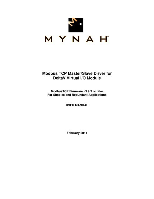
<strong>Modbus</strong> <strong>TCP</strong> <strong>Master</strong>/Slave <strong>Driver</strong> for<br />
DeltaV Virtual I/O Module<br />
<strong>Modbus</strong><strong>TCP</strong> Firmware v3.9.3 or later<br />
For Simplex and Redundant Applications<br />
USER MANUAL<br />
February 2011
Disclaimers<br />
©MYNAH <strong>Technologies</strong> 20069. All rights reserved.<br />
Designs are marks of MYNAH <strong>Technologies</strong>; Emerson Process Management, DeltaV, and the DeltaV<br />
design are marks of Emerson Process Management. All other marks are property of their respective<br />
owners.<br />
While this information is presented in good faith and believed to be accurate, <strong>Mynah</strong> <strong>Technologies</strong> does<br />
not guarantee satisfactory results from reliance upon such information. Nothing contained herein is to be<br />
construed as a warranty or guarantee, express or implied, regarding the performance, merchantability,<br />
fitness or any other matter with respect to the products, nor as a recommendation to use any product or<br />
process in conflict with any patent. <strong>Mynah</strong> <strong>Technologies</strong> reserves the right, without notice, to alter or<br />
improve the designs or specifications of the products described herein. All sales are governed by <strong>Mynah</strong><br />
<strong>Technologies</strong>’ terms and conditions, which are available on request.
Table of Contents<br />
1.0 Introduction .................................................................................................................................................... 2<br />
1.1 Scope ............................................................................................................................................................ 2<br />
1.2 Document Format ........................................................................................................................................ 2<br />
1.3 System Specifications .................................................................................................................................. 3<br />
2.0 Theory of Operation ....................................................................................................................................... 4<br />
2.1 DeltaV Native I/O ........................................................................................................................................ 5<br />
2.2 <strong>Modbus</strong> Devices ........................................................................................................................................... 6<br />
2.3 Messaging Options ....................................................................................................................................... 6<br />
2.4 <strong>Master</strong>/Slave Communications .................................................................................................................... 7<br />
3.0 VIMNet Explorer ............................................................................................................................................ 8<br />
3.1 Installation of Simplex Virtual I/O Module (VIM) Hardware ..................................................................... 8<br />
3.2 Installation of Redundant Virtual I/O Module (VIM) Hardware ................................................................. 9<br />
3.3 Installation of Software .............................................................................................................................. 10<br />
3.4 Configuring Simplex VIM ......................................................................................................................... 13<br />
3.5 Configuring Redundant VIM ..................................................................................................................... 19<br />
3.6 Uploading a VIM Configuration ................................................................................................................ 31<br />
3.7 Saving the VIM Configuration ................................................................................................................... 33<br />
3.8 Flash Upgrade of the VIM ......................................................................................................................... 39<br />
4.0 VIMNet Diagnostics ..................................................................................................................................... 42<br />
4.1 VIM Level Diagnostics & Statistics ........................................................................................................... 43<br />
4.2 Network Statistics ...................................................................................................................................... 45<br />
4.3 Redundancy Statistics ................................................................................................................................ 47<br />
4.4 Slave Statistics ........................................................................................................................................... 49<br />
4.5 Port Level Diagnostics ............................................................................................................................... 50<br />
4.6 Device Level Diagnostics .......................................................................................................................... 51<br />
4.7 Dataset Level Diagnostics .......................................................................................................................... 52<br />
4.8 Diagnostics Datasets .................................................................................................................................. 53<br />
5.0 Configuring DeltaV ...................................................................................................................................... 55<br />
5.1 Configure Datasets ..................................................................................................................................... 58<br />
5.2 Configuring a 16-bit dataset for Input/Holding Registers .......................................................................... 66<br />
5.3 Configuring a 16-bit dataset for Coils/Input Status bits ............................................................................. 68<br />
5.4 Configuring a Floating Point or 32-bit dataset ........................................................................................... 71<br />
5.5 Configuring a Boolean/Discrete dataset for Coils/Input Status data .......................................................... 73<br />
5.6 Configuring a dataset for VIM Diagnostics ............................................................................................... 75<br />
5.7 Customization ............................................................................................................................................ 78<br />
5.8 Dataset Scan Control .................................................................................................................................... 82<br />
5.9 Configuring <strong>Master</strong>/Slave Functionality .................................................................................................... 85<br />
6.0 Redundant I/O Communications .............................................................................................................. 104<br />
6.1 Redundancy Theory of Operations .......................................................................................................... 104<br />
6.2 The Ping ................................................................................................................................................... 110<br />
6.3 Simplex External Device .......................................................................................................................... 111<br />
6.4 Redundant External Device - Single Chassis with 2 NICs ....................................................................... 112<br />
6.5 Redundant External Device – 2 HSBY Chassis with 1 NIC Each ........................................................... 114<br />
6.6 Redundant External Device – 2 HSBY Chassis with 2 NICs Each .......................................................... 116<br />
6.7 User Application Initiated Redundant Switchover ................................................................................... 118<br />
6.8 Hot Replacement of faulty Redundant VIM ............................................................................................ 119<br />
7.0 Operational Check ...................................................................................................................................... 122<br />
7.1 Scope ........................................................................................................................................................ 122<br />
7.2 Verify Hardware and Software Version Number ..................................................................................... 122<br />
7.3 Verify Configuring ................................................................................................................................... 122<br />
7.4 Verify I/O Communication with Control Studio ...................................................................................... 122<br />
7.5 Using DeltaV Diagnostics ........................................................................................................................ 122<br />
7.6 LED Indication ......................................................................................................................................... 123<br />
8.0 Technical Support ...................................................................................................................................... 125
9.0 Example Use Cases ..................................................................................................................................... 126<br />
9.1 Schneider Quantum PLC HSBY – 2 NICs ............................................................................................... 126<br />
9.2 Schneider Quantum PLC HSBY – 4 NICs ............................................................................................... 128<br />
9.3 Invensys Triconex .................................................................................................................................... 129<br />
9.4 Bently Nevada .......................................................................................................................................... 133<br />
9.5 ControlLogix via ProSoft Card ................................................................................................................ 134<br />
9.6 Emerson S600 Flow Computer ................................................................................................................ 135
Table of Figures and Tables<br />
Table 1: <strong>Modbus</strong> <strong>TCP</strong> <strong>Driver</strong> System Specifications .................................................................................................... 3<br />
Figure 1: Simplex <strong>Modbus</strong> <strong>TCP</strong> Network ..................................................................................................................... 4<br />
Figure 2: Redundant <strong>Modbus</strong> <strong>TCP</strong> Network ................................................................................................................. 5<br />
Figure 3: Simplex VIM Assembly ................................................................................................................................. 8<br />
Figure 4: Redundant VIM Assembly ............................................................................................................................. 9<br />
Table 2: VIMNet Diagnostics ...................................................................................................................................... 44<br />
Table 3: VIMNet Diagnostics Dataset – Page 1 .......................................................................................................... 53<br />
Table 3: VIMNet Diagnostics Dataset – Page 1 (continued) ....................................................................................... 54<br />
Table 4: VIMNet Diagnostics Dataset – Page 2 .......................................................................................................... 54<br />
Table 4: PLC Data Type Values and Registers ........................................................................................................... 60<br />
Table 5: PLC Registers, Start Addresses, and Descriptions ........................................................................................ 60<br />
Table 6: DeltaV and PLC Registers ............................................................................................................................. 60<br />
Table 7a: Dataset Specification ................................................................................................................................... 61<br />
Table 7b: <strong>Modbus</strong> Read Function Codes ..................................................................................................................... 61<br />
Table 7c: <strong>Modbus</strong> Write Function Codes .................................................................................................................... 61<br />
Table 8: Ping Customization ..................................................................................................................................... 110<br />
Figure 5: Redundant VIMs with Simplex <strong>Modbus</strong> Devices ...................................................................................... 111<br />
Figure 6: Redundant VIMs with Redundant PLC Network Connections .................................................................. 112<br />
Table 9: Non-switching <strong>IP</strong>, VIM A Active ................................................................................................................ 113<br />
Table 10: Non-switching <strong>IP</strong>, VIM B Active .............................................................................................................. 113<br />
Figure 7: Redundant VIMs with PLC configured as Hot Backup, 2 NICs ................................................................ 114<br />
Table 11: Switching <strong>IP</strong>, VIM A Active ..................................................................................................................... 115<br />
Table 12: Switching <strong>IP</strong>, VIM B Active ..................................................................................................................... 115<br />
Figure 8: Redundant VIMs with PLC configured as Hot Backup, 4 NICs ................................................................ 116<br />
Figure 9: Redundant VIM Network ........................................................................................................................... 119<br />
Table 13: Verifying Hardware and Software Version Numbers ................................................................................ 122<br />
Table 14: LED Indication .......................................................................................................................................... 123<br />
Table 15: Simplex VIM LED State Specifications .................................................................................................... 123<br />
Table 16: Redundant VIM LED State Specifications ................................................................................................ 124
1.0 Introduction<br />
1.1 Scope<br />
<strong>Modbus</strong> <strong>TCP</strong> User Manual<br />
This document is the User Manual for the Virtual I/O Module (VIM) with the <strong>Modbus</strong><strong>TCP</strong> master driver<br />
firmware for the Emerson Process Management (EPM) DeltaV Control System. It provides the information<br />
required to install, configure, and maintain the driver firmware on the VIM. The reader should be familiar<br />
with EPM’s DeltaV Programmable Serial Interface Cards (PSIC), <strong>Modbus</strong> protocol, and connected external<br />
devices (supporting the <strong>Modbus</strong><strong>TCP</strong> protocol).<br />
The section Document Format briefly describes the contents of each section of this manual. System<br />
Specifications outlines hardware and software requirements for the <strong>Modbus</strong><strong>TCP</strong> <strong>Driver</strong> firmware.<br />
1.2 Document Format<br />
This document is organized as follows:<br />
Introduction Describes the scope and purpose of this document.<br />
Theory of Operation Provides a general functional overview of the<br />
<strong>Modbus</strong> <strong>TCP</strong> <strong>Driver</strong>.<br />
Firmware Flash Upgrade Describes procedures to upgrade the <strong>Modbus</strong> <strong>TCP</strong><br />
driver firmware in the VIM.<br />
DeltaV serial card Configuration Describes procedures and guidelines for configuring<br />
the DeltaV serial cards residing in the VIM.<br />
VIM network configuration Describes <strong>Modbus</strong> <strong>TCP</strong> network device<br />
configuration.<br />
Operational Check Provides tips and assistance to ensure the VIM is<br />
properly setup and configured.<br />
Technical Support Describes who to call if you need assistance.<br />
_____________________________________________________________________________________________________<br />
504 Trade Center Blvd. • Chesterfield, MO 63005 • Telephone (636) 681-1555 • Fax (636) 681-1660 • www.mynah.com<br />
2
1.3 System Specifications<br />
The following table lists the minimum system requirements for the <strong>Modbus</strong> <strong>TCP</strong> <strong>Driver</strong>:<br />
<strong>Modbus</strong> <strong>TCP</strong> User Manual<br />
Firmware <strong>Modbus</strong> <strong>TCP</strong> <strong>Driver</strong> Firmware, IOD-4101<br />
VIMNet Utility Windows PC resident VIMNet Explorer Utility.<br />
Protocol Compatibility <strong>Modbus</strong><strong>TCP</strong> protocol conforming to “MODBUS<br />
Messaging on <strong>TCP</strong>/<strong>IP</strong>, Implementation Guide”, Rev<br />
1.0, May 2002. This document is available from<br />
MODBUS.ORG<br />
Software Requirements DeltaV System Software (Release 6.3 or later)<br />
installed on a hardware-appropriate Windows<br />
workstation configured as a ProfessionalPlus for<br />
DeltaV<br />
Minimum DeltaV Hardware<br />
Requirements<br />
Serial Interface Port License (VE4102).<br />
For DeltaV 8.4 or earlier: One license is required for<br />
each serial port used. The VIM has a maximum of 8<br />
available serial ports.<br />
For DeltaV 9.3 or later: No serial port licenses are<br />
required. For DeltaV licenses, the VIM's datasets<br />
are counted based on DST usage.<br />
MYNAH VIM driver firmware IOD-4101<br />
DeltaV MD, MD Plus, MX and SX Controllers<br />
1 standard 2 wide controller carrier<br />
1 standard Power Supply<br />
VIM Hardware Requirements MYNAH VIM part no. MIM-4207 or VIM-4201<br />
Network Hardware<br />
Requirements<br />
Table 1: <strong>Modbus</strong> <strong>TCP</strong> <strong>Driver</strong> System Specifications<br />
For Simplex installation: 1 standard 2-wide controller<br />
carrier (Model Number VE3051C0) and 1 standard<br />
Power Supply (Model Number VE5008)<br />
For Redundant installation: 2 standard 2-wide<br />
controller carrier (Model Number VE3051C0) and 2<br />
standard Power Supply (Model Number VE5008).<br />
Use of VIM-4201 is recommended for redundant<br />
applications.<br />
Multiport 10/100BaseT Switch not shared with<br />
DeltaV Control Network. A single network switch or<br />
two network switches may be used for redundant<br />
communication.<br />
_____________________________________________________________________________________________________<br />
504 Trade Center Blvd. • Chesterfield, MO 63005 • Telephone (636) 681-1555 • Fax (636) 681-1660 • www.mynah.com<br />
3
2.0 Theory of Operation<br />
<strong>Modbus</strong> <strong>TCP</strong> User Manual<br />
The DeltaV Virtual I/O Module (VIM) provides a native DeltaV I/O interface to open plant Ethernet<br />
networks and devices that use <strong>Modbus</strong><strong>TCP</strong> (RTU <strong>TCP</strong>, RTU via <strong>TCP</strong> and RTU via UDP) protocol.<br />
DeltaV controllers can read and write signals from the plant floor devices that use these Ethernet<br />
networks such as PLCs, Motor Control Centers, and Weigh Scales. As such, the VIM is a Network<br />
Gateway between DeltaV controllers and external devices supporting network communications. This<br />
connectivity is illustrated below:<br />
Figure 1: Simplex <strong>Modbus</strong> <strong>TCP</strong> Network<br />
_____________________________________________________________________________________________________<br />
504 Trade Center Blvd. • Chesterfield, MO 63005 • Telephone (636) 681-1555 • Fax (636) 681-1660 • www.mynah.com<br />
4
2.1 DeltaV Native I/O<br />
Figure 2: Redundant <strong>Modbus</strong> <strong>TCP</strong> Network<br />
<strong>Modbus</strong> <strong>TCP</strong> User Manual<br />
The VIM provides a native DeltaV I/O interface by emulating four Programmable Serial Interface Cards<br />
(PSIC). By design, the VIM acquires the last 8-wide I/O carrier of a DeltaV system, emulating cards 57-60<br />
or 61-64 as a single, simplex unit. Installing 2 simplex VIMs side-by-side provides emulation of all 8 serial<br />
I/O cards 57-64. The configuration of card group 57-60 or 61-64, and network properties of connected<br />
external devices is done in the VIMNet Explorer described in Section 3.<br />
For redundancy support, the appropriate firmware (v 3.6.0 or later) must be flashed into the VIM. Four<br />
redundant PSICs are emulated when 2 VIMs are installed side-by-side and configured as a redundant<br />
pair. One VIM emulates all odd numbered serial cards, while the other VIM emulates all even numbered<br />
serial cards. The emulated serial cards behave as redundant pairs, i.e., 57/58, 59/60, etc. However, when<br />
redundancy switchover occurs, all cards behave as a bank and switch in unison. For example, if there is a<br />
_____________________________________________________________________________________________________<br />
504 Trade Center Blvd. • Chesterfield, MO 63005 • Telephone (636) 681-1555 • Fax (636) 681-1660 • www.mynah.com<br />
5
<strong>Modbus</strong> <strong>TCP</strong> User Manual<br />
communication error on card 57 that requires a switchover, the VIM will switch to its partner and cards 58,<br />
60, 62 and 64 will become active.<br />
The emulated serial cards appear to DeltaV as real serial I/O. The configuration of data tables to be read<br />
and written is done at the DeltaV Explorer level, in the same manner as required for a serial PLC device.<br />
This allows communications with any PLC or non-PLC device that supports the <strong>Modbus</strong> <strong>TCP</strong> messaging.<br />
Each PSIC has 2 ports configured under it. There are 16 datasets under each port. Consequently, the<br />
VIM has the capacity of 128 datasets. One dataset is equivalent to 100 16-bit registers, or 50 floating<br />
point (32 bit) registers. These 128 datasets are user mapped to PLC devices as required for your<br />
application.<br />
2.2 <strong>Modbus</strong> Devices<br />
The <strong>Modbus</strong> device address is considered unique in the serial cards port domain. Specifically, within a<br />
serial port, all configured <strong>Modbus</strong> devices are unique. You can, however, configure the same device with<br />
the same address under another port. For a device address configured more than once under more than<br />
one port, the <strong>IP</strong> address always remains unique.<br />
The VIMNet Explorer configuration correlates each unique <strong>Modbus</strong> address with an <strong>IP</strong> address. At the<br />
simplest level, each <strong>Modbus</strong> device equates to an <strong>IP</strong> address. In some cases, a single <strong>IP</strong> address may<br />
also be mapped to more than one <strong>Modbus</strong> device, as is typically required when interfacing with Motor<br />
Control Centers. In this case, the <strong>IP</strong> address mapped belongs to a bridge or gateway device, which in<br />
turn acts as a data concentrator communicating with multiple actual <strong>Modbus</strong> devices, each with a unique<br />
address.<br />
The bridge or gateway device typically communicates serially with its slaves. For example, <strong>Modbus</strong><br />
Ethernet Bridges manufactured by Schneider Electric (part # 174CEV30020 or TSX ETG 100) are such<br />
devices. These are network devices that communicate via <strong>Modbus</strong><strong>TCP</strong> with the VIM. The message<br />
packets are converted to standard <strong>Modbus</strong> and serially transmitted over RS-232 or RS-485 to slave<br />
devices. The subsequent responses are converted and transmitted to the VIM via <strong>Modbus</strong><strong>TCP</strong>. Because<br />
of the serial communications (maximum baud rate of 19.2k), you can expect message times of 1-2<br />
seconds.<br />
In Simplex mode, the VIM has the capacity to communicate with up to 32 network devices<br />
simultaneously. The communications tasks in the VIM are all active concurrently, each handling the<br />
messaging for the configured device (with its unique <strong>IP</strong> address). Of the 32 network devices, any mix of<br />
<strong>TCP</strong> and UDP devices can be configured. In Redundant mode, the VIM pair has the capacity to<br />
communicate with up to 16 network devices.<br />
In general each <strong>Modbus</strong> device is sent read/write requests for one dataset at a time. Depending on CPU<br />
load on the <strong>Modbus</strong> device the turn around can be as low as 10 msec. or as high as 200 msec. per<br />
dataset.<br />
To increase throughput some <strong>Modbus</strong> devices, e.g. Schnieider’s 140 NOE 77101 allow multiple<br />
connections, with each connection handling 16 messages simultaneously. The rules of Modicon CPU<br />
loading still apply, however, this mechanism allows for higher throughput. The VIM makes use of this by<br />
allowing you to configure the maximum messages per device. See section 3.4 for details.<br />
2.3 Messaging Options<br />
_____________________________________________________________________________________________________<br />
504 Trade Center Blvd. • Chesterfield, MO 63005 • Telephone (636) 681-1555 • Fax (636) 681-1660 • www.mynah.com<br />
6
<strong>Modbus</strong> <strong>TCP</strong> User Manual<br />
Devices configured in the VIM are configured to communicate using RTU <strong>TCP</strong>, RTU via <strong>TCP</strong> or RTU via<br />
UDP.<br />
• RTU <strong>TCP</strong> comprises the Open <strong>Modbus</strong><strong>TCP</strong> message structure. Message packets contain a 6byte<br />
header as defined by the <strong>Modbus</strong><strong>TCP</strong> standard. Messages are received and transmitted<br />
using <strong>TCP</strong>.<br />
• RTU via <strong>TCP</strong> is simply <strong>Modbus</strong> messaging encapsulated and transmitted over the network using<br />
<strong>TCP</strong>. Messages are received and transmitted using <strong>TCP</strong>.<br />
• RTU via UDP is similar to RTU via <strong>TCP</strong>. It is simply <strong>Modbus</strong> messaging transmitted over the<br />
network using UDP.<br />
2.4 <strong>Master</strong>/Slave Communications<br />
In Simplex mode, the VIM can simultaneously behave as a <strong>Master</strong> to external <strong>Modbus</strong> <strong>TCP</strong> slaves and as<br />
a Slave to external <strong>Modbus</strong> <strong>TCP</strong> masters. Slave functionality is not available in Redundant mode. In<br />
Redundant mode, the VIM can only behave as a <strong>Master</strong>.<br />
<strong>Master</strong>/Slave functionality is configured in DeltaV at the Serial cards port level. If a port is of <strong>Master</strong> type,<br />
then all underlying devices are considered to be external slaves to whom the VIM will actively connect as<br />
the master. If a port is of Slave type, then all underlying devices passively wait to be connected to by an<br />
external master.<br />
Because a simplex VIM can be both a <strong>Master</strong> and a Slave, it can be deployed in conjunction with other<br />
similarly configured VIMs for fast, VIM to VIM data exchange.<br />
The slave functionality is only available for RTU <strong>TCP</strong> type communications, i.e., communications using<br />
the Open <strong>Modbus</strong> <strong>TCP</strong> standard. Other communications using the RTU VIA <strong>TCP</strong> or RTU VIA UDP do not<br />
have slave support.<br />
The Slave device handler allows connections from 16 external <strong>Master</strong>s. Each open connection is handled<br />
by an independent task running in the VIM which maintains a 3 second timeout for received messages. If<br />
no request is received from the external <strong>Master</strong> in 3 seconds, the network connection is closed, and the<br />
connection task terminates. Other connection tasks continue to run, independently handling requests<br />
received from their respective <strong>Master</strong>s.<br />
In <strong>Master</strong> only mode, a Simplex VIM can communicate with a maximum of 32 external slave devices. By<br />
adding a slave port, the number of supported external slaves is reduced to 16. This allows 16 external<br />
<strong>Master</strong>s to connect to the VIM at the same time. Furthermore, in <strong>Master</strong> only mode, VIMs can be<br />
deployed as redundant pairs. For redundant VIMs, the maximum external slave’s is also 16.<br />
_____________________________________________________________________________________________________<br />
504 Trade Center Blvd. • Chesterfield, MO 63005 • Telephone (636) 681-1555 • Fax (636) 681-1660 • www.mynah.com<br />
7
3.0 VIMNet Explorer<br />
3.1 Installation of Simplex Virtual I/O Module (VIM) Hardware<br />
<strong>Modbus</strong> <strong>TCP</strong> User Manual<br />
Step 1 – You will need two 2-wide carriers, 2 power supplies, one DeltaV controller and one VIM. Mount<br />
a power supply on the left side and the DeltaV controller on the right side of one 2-wide carrier. The VIM<br />
can also be installed on the right side of the controller, but before any 8-wide is connected. Mount a<br />
power supply on the left side and the VIM on the right side of the second 2-wide carrier. Connect the<br />
second 2-wide carrier to the left edge of the Controller 2-wide carrier. Repeat this step for all simplex VIM<br />
installations. The final assembly should be as follows:<br />
Figure 3: Simplex VIM Assembly<br />
Step 2 – Connect a network cable from the VIM bottom port to a single isolated switch.<br />
Note<br />
Do not use the DeltaV Primary or Secondary switches for<br />
VIM external communications.<br />
Step 3 – Connect the PC with the VIMNet software to isolated switch connected to the VIM. The DeltaV<br />
ProPlus PC may be used to host the VIMNet Explorer. However, a separate network card must be used<br />
for VIMNet communications.<br />
_____________________________________________________________________________________________________<br />
504 Trade Center Blvd. • Chesterfield, MO 63005 • Telephone (636) 681-1555 • Fax (636) 681-1660 • www.mynah.com<br />
8
3.2 Installation of Redundant Virtual I/O Module (VIM) Hardware<br />
<strong>Modbus</strong> <strong>TCP</strong> User Manual<br />
Step 1 – You will need three 2-wide carriers, 3 power supplies, one DeltaV controller and two VIMs.<br />
Mount a power supply on the left side and the DeltaV controller on the right side of one 2-wide carrier.<br />
Mount a power supply on the left side and the VIM on the right side of the other two 2-wide carriers.<br />
Connect the two 2-wide VIM carriers together and to the left edge of the Controller 2-wide carrier. Repeat<br />
this step for all redundant VIM installations. The final assembly should be as follows:<br />
Figure 4: Redundant VIM Assembly<br />
Step 2 – Connect a network cable from each VIM Ethernet port to a separate dedicated isolated switch.<br />
Note<br />
Do not use the DeltaV Primary or Secondary<br />
switches for VIM external communications.<br />
Step 3 – Connect the PC with the VIMNet software to either one of the isolated switches connected to the<br />
VIMs. The DeltaV ProPlus PC may be used to host the VIMNet Explorer. However, a separate network<br />
card must be used for VIMNet communications.<br />
Step 4 – Connect the two switches together with a straight network cable. This is required so that the<br />
VIMs can communicate with each other. Configuration and status information is passed between the<br />
VIMs using this connection. If this cable is not installed, VIMs will not be visible to each other and DeltaV<br />
Diagnostics will show a Standby unavailable error message.<br />
Step 5 – If the VIM-4201 VIM hardware is used, the redundancy link port must also be connected<br />
between the VIM’s. The redundancy link cable (supplied by <strong>Mynah</strong>) has RJ11 connectors on both ends.<br />
The VIM’s use this connection to send/receive redundancy data to each other. The cable pinout is as<br />
follows:<br />
_____________________________________________________________________________________________________<br />
504 Trade Center Blvd. • Chesterfield, MO 63005 • Telephone (636) 681-1555 • Fax (636) 681-1660 • www.mynah.com<br />
9
3.3 Installation of Software<br />
<strong>Modbus</strong> <strong>TCP</strong> User Manual<br />
Software distribution is a single MSI file called VimNet.MSI as shown below. Double Click on VimNet.MSI<br />
to install VIMNet.<br />
Step 1 – Launch the VIM Plug & Play Server by going to Start –> Programs –> VIMNet Explorer -><br />
VIMNet Explorer.<br />
_____________________________________________________________________________________________________<br />
504 Trade Center Blvd. • Chesterfield, MO 63005 • Telephone (636) 681-1555 • Fax (636) 681-1660 • www.mynah.com<br />
10
The following main VIMNet Explorer screen will be displayed:<br />
<strong>Modbus</strong> <strong>TCP</strong> User Manual<br />
Step 2 - Right click on Physical Network go to Properties. You will be prompted to enter the <strong>IP</strong> Address<br />
of the network communicating with the VIM. The <strong>IP</strong> address shown is a default. Change this to the <strong>IP</strong><br />
address you are using, and then click OK.<br />
_____________________________________________________________________________________________________<br />
504 Trade Center Blvd. • Chesterfield, MO 63005 • Telephone (636) 681-1555 • Fax (636) 681-1660 • www.mynah.com<br />
11
<strong>Modbus</strong> <strong>TCP</strong> User Manual<br />
Step 3 – Right click on I/O Net and select New Controller menu option. This will create a controller object<br />
underneath I/O Net. The controller will have a default name, e.g., Node1. Rename the created controller<br />
to match the controller name in DeltaV.<br />
_____________________________________________________________________________________________________<br />
504 Trade Center Blvd. • Chesterfield, MO 63005 • Telephone (636) 681-1555 • Fax (636) 681-1660 • www.mynah.com<br />
12
3.4 Configuring Simplex VIM<br />
Step 1 – Right click on the Controller to Add Virtual I/O Module (VIM) placeholder.<br />
A dialog box will appear to Add Virtual IO Module:<br />
<strong>Modbus</strong> <strong>TCP</strong> User Manual<br />
Fill in the parameters as follows:<br />
a. Name – Unique 32 character VIM name<br />
b. <strong>IP</strong> Address – an <strong>IP</strong> address in your network which is not currently being used<br />
c. Subnet Mask – remains as default<br />
d. Gateway – Specify the <strong>IP</strong> address of the network router so the VIM can access devices on<br />
another network. Configure as 0.0.0.0 if a Gateway is not used.<br />
_____________________________________________________________________________________________________<br />
504 Trade Center Blvd. • Chesterfield, MO 63005 • Telephone (636) 681-1555 • Fax (636) 681-1660 • www.mynah.com<br />
13
<strong>Modbus</strong> <strong>TCP</strong> User Manual<br />
e. Virtual Cards – select card group to be emulated by VIM, i.e., cards 57-60, or 61-64<br />
f. Type – This is the VIM firmware type. Select <strong>Modbus</strong> <strong>TCP</strong>.<br />
g. Redundancy – Leave the “VIM is Redundant” checkbox unchecked.<br />
h. DeltaV version 10.x – click this checkbox if the DeltaV system is v10.3 or earlier, or v11.3<br />
with M-Series I/O. For v11.3 with S-Series I/O, this field is unchecked.<br />
Note that if the Gateway field is disabled; enable it via the Windows Registry.<br />
The key is EnableDefaultGateway, DWORD, with a value of 1.<br />
The key path is My Computer\HKEY_CURRENT_USER\Software\<strong>Mynah</strong> <strong>Technologies</strong>\PPV\Settings<br />
After filling out the parameters, select OK.<br />
The Virtual I/O placeholder module has been added (note that the Virtual Cards appear and you are<br />
ready to commission.<br />
Step 2 – Click on Decommissioned VIMs to display all available decommissioned VIMs. This list is<br />
dynamically populated as VIMs are detected on the network. Click the Decommissioned VIMs object in<br />
the left pane and verify the VIMs appear in the list in the right pane.<br />
_____________________________________________________________________________________________________<br />
504 Trade Center Blvd. • Chesterfield, MO 63005 • Telephone (636) 681-1555 • Fax (636) 681-1660 • www.mynah.com<br />
14
<strong>Modbus</strong> <strong>TCP</strong> User Manual<br />
Step 3 – Right click on the VIM placeholder under I/O Net and select the Commission menu option.<br />
a. Select the VIM to be commissioned from the List of Decommissioned VIMs. This will enable<br />
the OK button.<br />
b. Click the Ping button to ensure the <strong>IP</strong> address to be assigned is not already used. The result<br />
is shown as Address Available or unavailable.<br />
c. Select “Start Flashing” to identify the VIM you are commissioning. Once the correct VIM has<br />
been located, select Stop Flashing and then select OK.<br />
_____________________________________________________________________________________________________<br />
504 Trade Center Blvd. • Chesterfield, MO 63005 • Telephone (636) 681-1555 • Fax (636) 681-1660 • www.mynah.com<br />
15
<strong>Modbus</strong> <strong>TCP</strong> User Manual<br />
When commissioned, the Active LED will stay steady green and your state on the VIMNet Explorer will<br />
indicate that the VIM is Commissioned - Good. The Standby LED will remain off.<br />
Step 4 – Repeat Steps 1, 2 and 3 for all VIMs.<br />
Step 5 - To complete VIM configuration, network devices must be added to the virtual cards. Right click<br />
on the Serial Port and select Add Device.<br />
_____________________________________________________________________________________________________<br />
504 Trade Center Blvd. • Chesterfield, MO 63005 • Telephone (636) 681-1555 • Fax (636) 681-1660 • www.mynah.com<br />
16
<strong>Modbus</strong> <strong>TCP</strong> User Manual<br />
Fill in the Device parameters as follows:<br />
a. Device Address – 1-254. This is the PLC address of the device, which must be the same as the<br />
device address configured in the DeltaV Explorer for the device. Device address 255 is reserved.<br />
b. Description – up to 32 characters<br />
c. Click Add to add a new <strong>IP</strong> address and specify its properties. The following dialog will appear.<br />
Note that unused <strong>IP</strong> addresses are automatically discarded from the list. All configured and<br />
available <strong>IP</strong> addresses are shown in the list. You can map a device to any available <strong>IP</strong> address.<br />
Furthermore, more than one device can be mapped to a single <strong>IP</strong> address.<br />
Fill in the Device Communications parameters as follows:<br />
a. Specify the <strong>IP</strong> address of the <strong>Modbus</strong> <strong>TCP</strong> PLC device.<br />
b. Select the communication protocol to be used with the Device.<br />
c. Enter 502 for the standard <strong>Modbus</strong> <strong>TCP</strong> Port Number. This can be modified as needed for the<br />
external device.<br />
d. Adjust the Number of Simultaneous Messages (read requests) as needed. For example,<br />
Quantum PLCs allow a maximum of 16 requests. Write requests are always one at a time.<br />
e. Check the Gateway Device checkbox if this device is a Bridge which supports multiple<br />
simultaneous connections. For example, the Schneider <strong>Modbus</strong> Plus to Ethernet Bridge, part<br />
_____________________________________________________________________________________________________<br />
504 Trade Center Blvd. • Chesterfield, MO 63005 • Telephone (636) 681-1555 • Fax (636) 681-1660 • www.mynah.com<br />
17
<strong>Modbus</strong> <strong>TCP</strong> User Manual<br />
number 174 CEV 200 40, is one such gateway. Similarly, the Schneider <strong>Modbus</strong> <strong>TCP</strong> to Serial<br />
Bridge, part number TSX ETG 100, is also a gateway. When checked, the Max Sessions field will<br />
become enabled. Specify the maximum number of simultaneous sessions the VIM should open<br />
when connecting with the gateway. Messages on each session are handled independently.<br />
Click OK after filling the parameters. The following window shows multiple non-gateway devices<br />
configured.<br />
Note<br />
The mapping of device address to <strong>IP</strong> address is<br />
the most critical part of the VIM configuration.<br />
Care must be exercised to ensure correctness.<br />
When you are finished configuring VIMs, continue to Section 3.6. To configure Redundant VIMs,<br />
continue to Section 3.5.<br />
_____________________________________________________________________________________________________<br />
504 Trade Center Blvd. • Chesterfield, MO 63005 • Telephone (636) 681-1555 • Fax (636) 681-1660 • www.mynah.com<br />
18
3.5 Configuring Redundant VIM<br />
Step 1 – Right click on the Controller to Add Virtual I/O Module (VIM) placeholder.<br />
A dialog box will appear to Add <strong>Modbus</strong> <strong>TCP</strong> Virtual I/O Module<br />
<strong>Modbus</strong> <strong>TCP</strong> User Manual<br />
Fill in the parameters as follows:<br />
a. Name – Unique 32 character VIM name.<br />
b. <strong>IP</strong> Address – <strong>IP</strong> addresses in your network that are not currently being used. Click<br />
the Ping button to ensure that assigned <strong>IP</strong> addresses are unused.<br />
c. Subnet Mask – as required by your network architecture.<br />
_____________________________________________________________________________________________________<br />
504 Trade Center Blvd. • Chesterfield, MO 63005 • Telephone (636) 681-1555 • Fax (636) 681-1660 • www.mynah.com<br />
19
<strong>Modbus</strong> <strong>TCP</strong> User Manual<br />
d. Gateway – Specify the <strong>IP</strong> address of the network routers so the VIMs can access<br />
devices on another network. Configure as 0.0.0.0 if a Gateway is not used.<br />
e. Select the “VIM is Redundant” checkbox.<br />
f. Virtual Cards – All eight serial cards will be allocated as four redundant pairs.<br />
g. Type – This is the VIM firmware type. Select <strong>Modbus</strong> <strong>TCP</strong>.<br />
h. Check the VIM is Redundant checkbox.<br />
i. DeltaV version 10.x – click this checkbox if the DeltaV system is v10.3 or earlier, or<br />
v11.3 with M-Series I/O. For v11.3 with S-Series I/O, this field is unchecked.<br />
Note that if the Gateway field is disabled; enable it via the Windows Registry.<br />
The key is EnableDefaultGateway, DWORD, with a value of 1.<br />
The key path is My Computer\HKEY_CURRENT_USER\Software\<strong>Mynah</strong> <strong>Technologies</strong>\PPV\Settings<br />
After filling out the parameters, select OK. The Virtual I/O placeholder module has been added. (Note that<br />
the Virtual Cards appear and you are ready to commission.)<br />
Step 2 – Click on Decommissioned VIMs to display all available decommissioned VIMs. This list is<br />
dynamically populated as VIMs are detected on the network. Click the Decommissioned VIMs object in<br />
the left pane and verify the VIMs appear in the list in the right pane.<br />
_____________________________________________________________________________________________________<br />
504 Trade Center Blvd. • Chesterfield, MO 63005 • Telephone (636) 681-1555 • Fax (636) 681-1660 • www.mynah.com<br />
20
<strong>Modbus</strong> <strong>TCP</strong> User Manual<br />
Step 3 – Right click on the VIM placeholder under I/O Net and select the Commission menu option. You<br />
must commission both VIMs separately as VIM A and VIM B.<br />
Select the VIM to be commissioned from the list of Decommissioned VIMs.<br />
Select the Start Flashing Radio Button to identify the VIM you are commissioning. Once the<br />
correct VIM has been located, select Stop Flashing and then select OK.<br />
If the VIM cannot be located, check the network connection and power supply. Cancel the dialog<br />
and repeat Step 3.<br />
When commissioned, the Active LED will stay steady green for VIM A and your state on the VIMNet<br />
Explorer will indicate commission good. VIM B will indicate that it is commissioned by changing the<br />
Standby LED to steady green and it will turn off the Active LED. The Active and Standby LEDs state on<br />
both VIMs will change based on redundancy role. Only one LED will be active on a VIM at a time, i.e., the<br />
Active and Standby LED cannot both be lit at the same time on one VIM.<br />
_____________________________________________________________________________________________________<br />
504 Trade Center Blvd. • Chesterfield, MO 63005 • Telephone (636) 681-1555 • Fax (636) 681-1660 • www.mynah.com<br />
21
Step 4 – Repeat Step 3 for the partner VIM.<br />
<strong>Modbus</strong> <strong>TCP</strong> User Manual<br />
Step 5 - To complete VIM configuration, Network devices must be added to the Virtual Cards. Right Click<br />
on the Serial Port and select the Add Device menu option.<br />
Adding a Non-Gateway Device<br />
Right click on the port and select Add Device as follows:<br />
Fill in the parameters as follows:<br />
a. Device Address – 1-254. This is the PLC address of the device, which must be the same<br />
as the device address configured in the DeltaV explorer for the serial card. Address 255<br />
is reserved.<br />
b. Description – up to 32 characters<br />
c. Click Add to add a new <strong>IP</strong> address and specify its properties. The following dialog will<br />
appear. Note that unused <strong>IP</strong> addresses are automatically discarded from the list. All<br />
configured and available <strong>IP</strong> addresses are shown in the list. You can map a device to any<br />
_____________________________________________________________________________________________________<br />
504 Trade Center Blvd. • Chesterfield, MO 63005 • Telephone (636) 681-1555 • Fax (636) 681-1660 • www.mynah.com<br />
22
In this dialog:<br />
<strong>Modbus</strong> <strong>TCP</strong> User Manual<br />
available <strong>IP</strong> address. Furthermore, more than one device can be mapped to a single <strong>IP</strong><br />
address.<br />
a. Specify the <strong>IP</strong> address of the <strong>Modbus</strong> <strong>TCP</strong> PLC device.<br />
b. If redundant, select the type of device redundancy being used. Device redundancy is described in<br />
Section 7.<br />
c. Enter 502 for the standard <strong>Modbus</strong> <strong>TCP</strong> Port Number. This can be modified as needed for the<br />
external device.<br />
d. Adjust the Number of Simultaneous Messages (read requests) as needed. For example,<br />
Quantum PLCs allow a maximum of 16 requests. Write requests are always one at a time.<br />
e. The Gateway Device checkbox should remain unchecked.<br />
Click OK after filling the parameters. The following window shows one non-gateway redundant device<br />
configured.<br />
_____________________________________________________________________________________________________<br />
504 Trade Center Blvd. • Chesterfield, MO 63005 • Telephone (636) 681-1555 • Fax (636) 681-1660 • www.mynah.com<br />
23
Adding a Gateway Device<br />
<strong>Modbus</strong> <strong>TCP</strong> User Manual<br />
A Gateway device is one which supports multiple simultaneous network connections. Each connection<br />
opens a path to one of the underlying sub-devices as illustrated below with <strong>Modbus</strong> Plus Gateway.<br />
Right click on the port and select Add Device as follows:<br />
_____________________________________________________________________________________________________<br />
504 Trade Center Blvd. • Chesterfield, MO 63005 • Telephone (636) 681-1555 • Fax (636) 681-1660 • www.mynah.com<br />
24
<strong>Modbus</strong> <strong>TCP</strong> User Manual<br />
Fill in the parameters as follows:<br />
a. Device Address – 1-254. This is the PLC address of the device, which must be the same<br />
as the device address configured in the DeltaV explorer for the serial card. Address 255<br />
is reserved.<br />
b. Description – up to 32 characters<br />
c. Click Add to add a new <strong>IP</strong> address and specify its properties. The following dialog will<br />
appear. Note that unused <strong>IP</strong> addresses are automatically discarded from the list. All<br />
configured and available <strong>IP</strong> addresses are shown in the list. You can map a device to any<br />
available <strong>IP</strong> address. Furthermore, more than one device can be mapped to a single <strong>IP</strong><br />
address.<br />
_____________________________________________________________________________________________________<br />
504 Trade Center Blvd. • Chesterfield, MO 63005 • Telephone (636) 681-1555 • Fax (636) 681-1660 • www.mynah.com<br />
25
In this dialog:<br />
<strong>Modbus</strong> <strong>TCP</strong> User Manual<br />
a. Specify the <strong>IP</strong> address of the <strong>Modbus</strong> <strong>TCP</strong> PLC device.<br />
b. Select the type of device redundancy being used. Device redundancy is described in Section<br />
7. In this case, two <strong>Modbus</strong> Plus Gateways would be required.<br />
c. Enter 502 for the standard <strong>Modbus</strong> <strong>TCP</strong> Port Number. This can be modified as needed for<br />
the external device.<br />
d. Adjust the Number of Simultaneous Messages (read requests) as needed. For example,<br />
Quantum PLCs allow a maximum of 16 requests. Write requests are always one at a time.<br />
e. Check the Gateway Device checkbox. The device being configured must be a Gateway<br />
which supports multiple simultaneous connections. For example, the Schneider <strong>Modbus</strong> Plus<br />
to Ethernet Bridge, part number 174 CEV 200 40, is one such gateway shown in above<br />
illustration. Similarly, the Schneider <strong>Modbus</strong> <strong>TCP</strong> to serial converter, part number TSX ETG<br />
100, is also a gateway. When checked, the Max Sessions field will become enabled. Specify<br />
the maximum number of simultaneous sessions the VIM should open when connecting with<br />
the gateway. Messages on each session are handled independently. In this example, we<br />
have selected 4 simultaneous sessions.<br />
Click OK after filling the parameters. Repeat the above steps to add additional devices, selecting the<br />
existing <strong>IP</strong> address pair, and the same or different session number. The following window shows one<br />
gateway redundant device configured. This device exists in 4 sessions. Based on this, the VIM will open 4<br />
independent, simultaneous connections to the device. Note that each device uses the same <strong>IP</strong> address<br />
pair.<br />
_____________________________________________________________________________________________________<br />
504 Trade Center Blvd. • Chesterfield, MO 63005 • Telephone (636) 681-1555 • Fax (636) 681-1660 • www.mynah.com<br />
26
<strong>Modbus</strong> <strong>TCP</strong> User Manual<br />
_____________________________________________________________________________________________________<br />
504 Trade Center Blvd. • Chesterfield, MO 63005 • Telephone (636) 681-1555 • Fax (636) 681-1660 • www.mynah.com<br />
27
Adding a Bridge Device<br />
<strong>Modbus</strong> <strong>TCP</strong> User Manual<br />
A Bridge device is different from a Gateway device in that it only supports one network session. The<br />
underlying devices are usually connected to the Bridge via RS485 in a multi-drop architecture as shown<br />
below. The open connection multiplexes between the connected sub-devices. However this architecture<br />
delivers limited throughput. Loss of one sub-device can severely disrupt communications with the<br />
remaining sub-devices. Such architectures are not recommended, unless one bridge/one device is used.<br />
Right click on the port and select Add Device as follows:<br />
_____________________________________________________________________________________________________<br />
504 Trade Center Blvd. • Chesterfield, MO 63005 • Telephone (636) 681-1555 • Fax (636) 681-1660 • www.mynah.com<br />
28
<strong>Modbus</strong> <strong>TCP</strong> User Manual<br />
Fill in the parameters as follows:<br />
a. Device Address – 1-254. This is the PLC address of the device, which must be the same<br />
as the device address configured in the DeltaV explorer for the serial card. Address 255<br />
is reserved.<br />
b. Description – up to 32 characters<br />
c. Click Add to add a new <strong>IP</strong> address and specify its properties. The following dialog will<br />
appear. Note that unused <strong>IP</strong> addresses are automatically discarded from the list. All<br />
configured and available <strong>IP</strong> addresses are shown in the list. You can map a device to any<br />
available <strong>IP</strong> address. Furthermore, more than one device can be mapped to a single <strong>IP</strong><br />
address.<br />
In this dialog:<br />
a. Specify the <strong>IP</strong> address of the <strong>Modbus</strong> <strong>TCP</strong> PLC device.<br />
b. A bridge is usually deployed as a simplex device.<br />
_____________________________________________________________________________________________________<br />
504 Trade Center Blvd. • Chesterfield, MO 63005 • Telephone (636) 681-1555 • Fax (636) 681-1660 • www.mynah.com<br />
29
<strong>Modbus</strong> <strong>TCP</strong> User Manual<br />
c. Enter 502 for the standard <strong>Modbus</strong> <strong>TCP</strong> Port Number. This can be modified as needed for<br />
the external device.<br />
d. Simultaneous Messages (read requests) must be set to 1.<br />
e. Leave the Gateway Device checkbox unchecked.<br />
Click OK after filling the parameters. Repeat the above steps to add additional devices, specifying the<br />
same existing <strong>IP</strong> address. The following window shows one bridge device configured. This bridge has 3<br />
underlying sub-devices, all sharing the same <strong>IP</strong> address but the device address is different. See Section<br />
5.7 for additional dataset level flags required for bridged device communications.<br />
_____________________________________________________________________________________________________<br />
504 Trade Center Blvd. • Chesterfield, MO 63005 • Telephone (636) 681-1555 • Fax (636) 681-1660 • www.mynah.com<br />
30
3.6 Uploading a VIM Configuration<br />
<strong>Modbus</strong> <strong>TCP</strong> User Manual<br />
VIMNet configuration creates a mapping between PLC device addresses and <strong>IP</strong> addresses. This<br />
mapping must be uploaded into the VIM for proper communications. A configuration that has not been<br />
uploaded to the VIM is indicated with a blue triangle next to the VIM icon. To upload a configuration, the<br />
VIM must first be commissioned.<br />
Right click on the VIM and select VIM Configuration Upload.<br />
Uploading a new configuration into the VIM will cause all external<br />
communications to terminate. After upload completion, the VIM<br />
will automatically reboot and reconnect to the external devices.<br />
VIM upload must be done with the process in safe mode.<br />
For simplex VIMs, the upload is direct. For redundant VIMs, the upload can be one VIM at a time, or both<br />
VIMs together. Note that if the VIMs are online, then uploading one at a time is recommended. Only the<br />
uploaded VIM will lose connections with the field. In this case, the Standby VIM should be uploaded first.<br />
Then from DeltaV Diagnostics, a VIM switchover should be executed, followed by an upload to the new<br />
Standby VIM. The upload procedure is as follows. When selected, the following warning is displayed:<br />
Click Yes to continue. The uploading VIM Configuration progress bar will indicate the status of the upload:<br />
_____________________________________________________________________________________________________<br />
504 Trade Center Blvd. • Chesterfield, MO 63005 • Telephone (636) 681-1555 • Fax (636) 681-1660 • www.mynah.com<br />
31
Upon successful completion of the VIM Configuration Upload, click OK.<br />
<strong>Modbus</strong> <strong>TCP</strong> User Manual<br />
The upload process terminates all communications with DeltaV over the railbus. Upon upload completion,<br />
the VIM automatically reboots and goes online. Click OK to terminate the dialog.<br />
If your upload is unsuccessful, try again. Contact MYNAH Support if you are not successful in uploading.<br />
_____________________________________________________________________________________________________<br />
504 Trade Center Blvd. • Chesterfield, MO 63005 • Telephone (636) 681-1555 • Fax (636) 681-1660 • www.mynah.com<br />
32
3.7 Saving the VIM Configuration<br />
<strong>Modbus</strong> <strong>TCP</strong> User Manual<br />
VIMNet configuration is saved in a file with a .VIO extension. This file can be located anywhere in the PC<br />
local or network folder. The current state of commissioned VIMs, as well as VIM network device<br />
configurations is contained in this file.<br />
Note<br />
The VIO configuration file is very important, and<br />
must be saved in a safe location for future<br />
access to the VIM network for modification and<br />
troubleshooting.<br />
Failure to do so results in unnecessary loss of<br />
network information, which must then be<br />
recreated.<br />
The VIMNet Explorer does not have to be online all the time. However, if it is restarted, this file should be<br />
reopened so that the current state of VIMs does not show as error.<br />
When the VIMNet Explorer is restarted, it will start scanning for VIMs on the network, and display what is<br />
found. Commissioned VIMs found on the network will be compared with configured placeholders and<br />
there current state displayed. Mismatched VIMs, i.e., those which do not exist as placeholders, or<br />
mismatches in MAC address or <strong>IP</strong> address will be displayed in the Decommissioned list as errors. The<br />
following shows VIMs in error.<br />
If the original configuration file is not available, the VIMs in error must be manually cleared. The options<br />
are to either Reset the VIM in the Decommissioned list, Reconcile or Recover the contained configuration<br />
as described below.<br />
_____________________________________________________________________________________________________<br />
504 Trade Center Blvd. • Chesterfield, MO 63005 • Telephone (636) 681-1555 • Fax (636) 681-1660 • www.mynah.com<br />
33
Reset VIM<br />
<strong>Modbus</strong> <strong>TCP</strong> User Manual<br />
To Reset a VIM, right click on the VIM in the Decommissioned list to get the context menu. Then select<br />
Reset as shown below. The VIMNet Explorer will send a Decommission command over the network, and<br />
clear the VIM from its list. It is anticipated that the Decommission command will be accepted by the VIM<br />
resulting in a decommissioned VIM. The VIM will then appear as an unconfigured, decommissioned VIM<br />
in the VIMNet Explorer list.<br />
Performing a Reset will decommission a VIM. This will terminate<br />
all external communications.<br />
_____________________________________________________________________________________________________<br />
504 Trade Center Blvd. • Chesterfield, MO 63005 • Telephone (636) 681-1555 • Fax (636) 681-1660 • www.mynah.com<br />
34
Recover Configuration<br />
<strong>Modbus</strong> <strong>TCP</strong> User Manual<br />
The configuration contained in a VIM can be read back and saved in the VIMNet Explorer.To Recover<br />
Configuration, right click on the VIM in the Decommissioned list to get the context menu. Then select<br />
Recover Configuration as shown below. In this example, we have a redundant pair of VIMs. The simplex<br />
VIM process is identical.<br />
The progress bar will show configuration read back progress.<br />
Once the configuration has been retrieved, the following dialog will prompt for the controller name where<br />
it will be saved.<br />
Click New to get a new name or select a name from the list, then click OK. In the following prompt, select<br />
Yes.<br />
_____________________________________________________________________________________________________<br />
504 Trade Center Blvd. • Chesterfield, MO 63005 • Telephone (636) 681-1555 • Fax (636) 681-1660 • www.mynah.com<br />
35
<strong>Modbus</strong> <strong>TCP</strong> User Manual<br />
The configuration retrieved will be saved under Node1 and VIM01 as Odd cards. Repeat the same<br />
process for the partner card. In the following dialog, select OK.<br />
The following dialog will be displayed. Click Yes.<br />
This completes the configuration recovery process.<br />
_____________________________________________________________________________________________________<br />
504 Trade Center Blvd. • Chesterfield, MO 63005 • Telephone (636) 681-1555 • Fax (636) 681-1660 • www.mynah.com<br />
36
Reconcile VIM<br />
<strong>Modbus</strong> <strong>TCP</strong> User Manual<br />
The process of reconciling a detected, commissioned VIM, with an unassigned placeholder allows you to<br />
reconstruct a configuration file without decommissioning and then recommissioning the VIM. Detected<br />
VIMs are displayed in the Decommissioned VIMs list with a status of Commissioned – Unknown.<br />
To Reconcile a VIM, first create a new placeholder with the same <strong>IP</strong> address as the VIMs in the<br />
decommissioned list. Next, right click on the VIM in the I/O Net to get the context menu, then select<br />
Reconcile VIM menu option as shown below.<br />
This will launch a dialog as follows, showing all the detected, commissioned, and unattached VIMS.<br />
Select a VIM in the list and click OK. If the VIM placeholder is redundant and both VIMs are unattached, a<br />
dialog will be displayed as follows where you can select VIM A or VIM B.<br />
_____________________________________________________________________________________________________<br />
504 Trade Center Blvd. • Chesterfield, MO 63005 • Telephone (636) 681-1555 • Fax (636) 681-1660 • www.mynah.com<br />
37
<strong>Modbus</strong> <strong>TCP</strong> User Manual<br />
If the VIM placeholder is simplex or if only one VIM out of a redundant pair is unattached, the reconcile<br />
process with immediately create the link without further prompts.<br />
The reconciled VIM will appear as normal and commissioned, and the decommissioned list will be<br />
cleared. Note that if you are creating a new configuration file, you must recreate the external device<br />
network definitions and then upload to the VIM.<br />
_____________________________________________________________________________________________________<br />
504 Trade Center Blvd. • Chesterfield, MO 63005 • Telephone (636) 681-1555 • Fax (636) 681-1660 • www.mynah.com<br />
38
3.8 Flash Upgrade of the VIM<br />
<strong>Modbus</strong> <strong>TCP</strong> User Manual<br />
For VIM functionality changes, MYNAH <strong>Technologies</strong> will issue firmware upgrade files as required. The<br />
new firmware files must be flashed into the VIM.<br />
If your current operating firmware version is v3.5.7 or earlier, please contact <strong>Mynah</strong> technical support for<br />
instructions on how to upgrade to the latest system.<br />
Flashing a Simplex VIM with new firmware will<br />
cause all external communications to terminate.<br />
Upon flash completion, the VIM will automatically<br />
reboot.<br />
Flashing a Redundant VIM pair must begin with the<br />
standby unit. Upon flash completion, the VIM will<br />
automatically reboot and go back to standby state.<br />
Use DeltaV Diagnostics to initiate a switchover such<br />
that the standby unit becomes active. Next flash the<br />
new standby unit.<br />
VIM flash must be done with the process in safe<br />
mode.<br />
To do this, right click on the target VIM object and select Properties. The following dialog box will appear:<br />
_____________________________________________________________________________________________________<br />
504 Trade Center Blvd. • Chesterfield, MO 63005 • Telephone (636) 681-1555 • Fax (636) 681-1660 • www.mynah.com<br />
39
Click Flash Upgrade. A warning will appear as follows:<br />
<strong>Modbus</strong> <strong>TCP</strong> User Manual<br />
Click Yes to start the flash process. Note that while flashing the VIM, all communications with DeltaV<br />
Controller are terminated.<br />
Browse to select the firmware file. Firmware files have a .HEX extension. Please contact <strong>Mynah</strong><br />
Technical Support for the correct file to use.<br />
_____________________________________________________________________________________________________<br />
504 Trade Center Blvd. • Chesterfield, MO 63005 • Telephone (636) 681-1555 • Fax (636) 681-1660 • www.mynah.com<br />
40
Using an incorrect firmware file may<br />
render the VIM inoperable.<br />
Select the file to continue the flash upgrade process.<br />
<strong>Modbus</strong> <strong>TCP</strong> User Manual<br />
Note that the file format for the VIM should be:<br />
vim-modbustcp-vmajor version.minor version.maintenance build.full.hex. For example, see the file<br />
name in above dialog.<br />
Once the file has been selected, a connection is opened to the VIM and the flash system is downloaded.<br />
During the download, a progress bar will display as follows:<br />
Upon completion, the VIM will reboot and go online.<br />
In case of redundant VIMs, both must be flashed separately to the same firmware revision.<br />
_____________________________________________________________________________________________________<br />
504 Trade Center Blvd. • Chesterfield, MO 63005 • Telephone (636) 681-1555 • Fax (636) 681-1660 • www.mynah.com<br />
41
4.0 VIMNet Diagnostics<br />
<strong>Modbus</strong> <strong>TCP</strong> User Manual<br />
VIMNet Diagnostics are provided to assist you in troubleshooting abnormal situations, and to view<br />
network communications statistics. VIMNet Diagnostics can be launched multiple times, once for each<br />
active VIM in the network. Or a single instance of Diagnostics can be used to view all active VIMs.<br />
Launch the Diagnostics application by right clicking on the commissioned VIM in the VIMNet Explorer as<br />
follows:<br />
Note that in general diagnostics for simplex and redundant VIMs are identical. Some differences exist,<br />
however.<br />
When the diagnostics application is launched, it opens a network connection with the VIM specifically to<br />
read diagnostic information. The information is continuously scanned and displayed in the window. You<br />
can select the scan rate. However, the default rate is 1 second.<br />
Diagnostic information is displayed at each level of the VIM architecture. You can drill down to the dataset<br />
level, which is the lowest level. The following screens show diagnostic information at each level, starting<br />
with the VIM level.<br />
_____________________________________________________________________________________________________<br />
504 Trade Center Blvd. • Chesterfield, MO 63005 • Telephone (636) 681-1555 • Fax (636) 681-1660 • www.mynah.com<br />
42
4.1 VIM Level Diagnostics & Statistics<br />
<strong>Modbus</strong> <strong>TCP</strong> User Manual<br />
The first screen after launch is as follows if the VIM is redundant. If the VIM is simplex, the VIM B column<br />
is not displayed:<br />
_____________________________________________________________________________________________________<br />
504 Trade Center Blvd. • Chesterfield, MO 63005 • Telephone (636) 681-1555 • Fax (636) 681-1660 • www.mynah.com<br />
43
<strong>Modbus</strong> <strong>TCP</strong> User Manual<br />
The information displayed in this window is explained in Table 2 below. Users can configure diagnostics<br />
datasets in DeltaV to read this information into the controller. This is discussed further in Section 4.8.<br />
Diagnostic Item Description<br />
VIM Mode Shows current mode: Commissioned, Failsafe, etc.0 – Normal Online, 1 – FailSafe<br />
Data Poll Queue Number of messages waiting to be sent to DeltaV<br />
Pending Message Queue Number of waiting diagnostics message responses to be sent to DeltaV<br />
Railbus Message Queue Number of waiting Railbus messages received from DeltaV to be processed<br />
Serial Bus Poll Counter of poll requests received from Controller<br />
Dataset Value Reads Counter of dataset value read requests received from Controller<br />
Dataset Value Writes Counter of dataset value write requests received from Controller<br />
Default Reads Counter of default read requests received from Controller<br />
Pending Data Reads Counter of DeltaV Diagnostics data read requests received from Controller<br />
Pending Data Writes Counter of DeltaV Diagnostics data write requests received from Controller<br />
Railbus Ticker Ticker of process handling Railbus messages<br />
Plug and Play Ticker Ticker of process handling Plug/Play messages<br />
Dataset Handler Ticker Ticker of process handling dataset updates<br />
<strong>IP</strong> Address <strong>IP</strong> address of VIM<br />
DeltaV Devices Number of DeltaV devices in configuration received from Controller<br />
Network Devices Number of actual network devices configured/found<br />
Application Application type: <strong>Modbus</strong> <strong>TCP</strong><br />
Flash I/O Step Reserved for Flash evaluation<br />
Flash I/O Connected Reserved for Flash evaluation<br />
Flash I/O Error Reserved for Flash evaluation<br />
Logging to <strong>IP</strong> address of PC if message logging is turned on<br />
Total # DS Total number of datasets in this configuration<br />
Maximum DS Scan (ms) Maximum scan time (ms) for single dataset based on 16 simultaneous messages<br />
Minimum DS Scan (ms) Minimum scan time (ms) for single dataset based on 16 simultaneous messages<br />
Average DS Scan (ms) Average scan time (ms) for single dataset based on 16 simultaneous messages<br />
Maximum Scan (ms) Maximum scan time (ms) for all datasets<br />
Minimum Scan (ms) Minimum scan time (ms) for all datasets<br />
Average Scan (ms) Average scan time (ms) for all datasets<br />
Maximum Msgs(/s) Maximum messages per second<br />
Minimum Msgs (/s) Minimum messages per second<br />
Average Msgs (/s) Average messages per second<br />
Generation Rate (/s) Rate of DS changes detected in field data<br />
Poll Rate (/s) Rate of DS Polls received from DeltaV controller<br />
Number of buffers Total number of available buffers for Railbus message handling (max 255)<br />
% Available Buffers Percent of available buffers<br />
Buffer Resets Count of buffer resets (internal VIM memory management)<br />
Table 2: VIMNet Diagnostics<br />
_____________________________________________________________________________________________________<br />
504 Trade Center Blvd. • Chesterfield, MO 63005 • Telephone (636) 681-1555 • Fax (636) 681-1660 • www.mynah.com<br />
44
<strong>Modbus</strong> <strong>TCP</strong> User Manual<br />
You can right click on the VIM to get a context menu. From this menu, you can clear all statistics by<br />
selecting Reset All Statistics.<br />
4.2 Network Statistics<br />
Right click on the VIM to get a context menu. From this menu, low level Ethernet Network Statistics can<br />
be displayed for simplex or redundant VIMs. The screenshot below shows statistics for VIM A in a<br />
redundant pair.<br />
_____________________________________________________________________________________________________<br />
504 Trade Center Blvd. • Chesterfield, MO 63005 • Telephone (636) 681-1555 • Fax (636) 681-1660 • www.mynah.com<br />
45
<strong>Modbus</strong> <strong>TCP</strong> User Manual<br />
_____________________________________________________________________________________________________<br />
504 Trade Center Blvd. • Chesterfield, MO 63005 • Telephone (636) 681-1555 • Fax (636) 681-1660 • www.mynah.com<br />
46
4.3 Redundancy Statistics<br />
<strong>Modbus</strong> <strong>TCP</strong> User Manual<br />
Right click on the VIM to get a context menu. From this menu, Redundancy Statistics can be displayed.<br />
The screenshot below shows statistics for Active VIM A in a redundant pair.<br />
_____________________________________________________________________________________________________<br />
504 Trade Center Blvd. • Chesterfield, MO 63005 • Telephone (636) 681-1555 • Fax (636) 681-1660 • www.mynah.com<br />
47
<strong>Modbus</strong> <strong>TCP</strong> User Manual<br />
_____________________________________________________________________________________________________<br />
504 Trade Center Blvd. • Chesterfield, MO 63005 • Telephone (636) 681-1555 • Fax (636) 681-1660 • www.mynah.com<br />
48
4.4 Slave Statistics<br />
<strong>Modbus</strong> <strong>TCP</strong> User Manual<br />
Right click on the Simplex VIM to get a context menu. From this menu, Slave Statistics can be displayed,<br />
which will show all connected external master devices.<br />
_____________________________________________________________________________________________________<br />
504 Trade Center Blvd. • Chesterfield, MO 63005 • Telephone (636) 681-1555 • Fax (636) 681-1660 • www.mynah.com<br />
49
4.5 Port Level Diagnostics<br />
<strong>Modbus</strong> <strong>TCP</strong> User Manual<br />
Port level diagnostics show the port status, as well as status of datasets. Dataset status is shown as a<br />
character string corresponding to any error which might exist. This same error string is also displayed in<br />
DeltaV Diagnostics.<br />
Note that if the serial card is redundant, only the odd numbered card is shown in the left pane. In the right<br />
pane, the actual active card is shown depending on Active VIM.<br />
The Link Status and Channel Status are shown as hexadecimal error codes. The Error Message column<br />
contains any error that might exist. If no error exists, then the status shown is Good.<br />
_____________________________________________________________________________________________________<br />
504 Trade Center Blvd. • Chesterfield, MO 63005 • Telephone (636) 681-1555 • Fax (636) 681-1660 • www.mynah.com<br />
50
4.6 Device Level Diagnostics<br />
Device level diagnostics show the statistics for selected device as follows:<br />
<strong>Modbus</strong> <strong>TCP</strong> User Manual<br />
You can right click on the device to get a context menu as follows. This menu allows you to reset the<br />
statistics and also to search for configured datasets in this device.<br />
_____________________________________________________________________________________________________<br />
504 Trade Center Blvd. • Chesterfield, MO 63005 • Telephone (636) 681-1555 • Fax (636) 681-1660 • www.mynah.com<br />
51
4.7 Dataset Level Diagnostics<br />
<strong>Modbus</strong> <strong>TCP</strong> User Manual<br />
By clicking on the individual dataset under Device diagnostics, you will get the dataset specific diagnostic<br />
information as follows:<br />
Items of specific interest at this level are the Dataset Scan and the Time Between Scans. These pieces of<br />
information tell us what the scan time for this dataset is, and how much time elapses between two<br />
consecutive scans.<br />
_____________________________________________________________________________________________________<br />
504 Trade Center Blvd. • Chesterfield, MO 63005 • Telephone (636) 681-1555 • Fax (636) 681-1660 • www.mynah.com<br />
52
4.8 Diagnostics Datasets<br />
<strong>Modbus</strong> <strong>TCP</strong> User Manual<br />
This VIMNet diagnostics information can also sent to DeltaV if diagnostics datasets are configured. There<br />
are two diagnostics dataset pages. Please refer to Section 5 for dataset configuration. The data<br />
transmitted to DeltaV datasets is as follows:<br />
Register Diagnostics Value<br />
R1 VIM Mode<br />
O – Normal Online<br />
1 – FailSafe Mode<br />
R2 Number of Network devices<br />
R3 Data Poll Queue<br />
R4 Pending Message Queue<br />
R5 Railbus Message Queue<br />
R6 Counter - Serial Bus Poll<br />
R7 Counter – Dataset Value Reads<br />
R8 Counter – Dataset Value Writes<br />
R9 Counter – Default Reads<br />
R10 Counter – Pending Data Reads<br />
R11 Counter – Pending Data Writes<br />
R12 Total number of Datasets<br />
R13 Maximum DS Scan<br />
R14 Minimum DS Scan<br />
R15 Average DS Scan<br />
R16 Maximum Messages<br />
R17 Minimum Messages<br />
R18 Average Messages<br />
R19 Maximum Scan Time<br />
R20 Minimum Scan Time<br />
R21 Average Scan Time<br />
R22 Ticker - Railbus message handler<br />
R23 Ticker – Plug and Play message handler<br />
R24 Ticker – Dataset handler<br />
R25 Rate of DS changes detected<br />
R26 Rate of DS Polls received<br />
R27 Logger <strong>IP</strong> address<br />
R28 VIM Application type as configured<br />
1 = <strong>Modbus</strong><strong>TCP</strong> – cards 57-60<br />
3 = <strong>Modbus</strong><strong>TCP</strong> – cards 61-64<br />
5 = <strong>Modbus</strong><strong>TCP</strong> – Odd cards 57, 59, 61, 63 – if Odd cards Active<br />
7 = <strong>Modbus</strong><strong>TCP</strong> – Even cards 58, 60, 62, 64 – if Even cards Active<br />
R29 Current redundancy State<br />
Bits 0-3 are the VIM State as follows:<br />
0000 – Decommissioned<br />
0001 – Commissioned<br />
0010 – Flash Mode<br />
0011 – Configuration Mode<br />
Bits 4-5 are the Redundancy state as follows:<br />
00 – Simplex<br />
01 – Redundant Active<br />
02 – Redundant Backup<br />
Note that DeltaV always reads the Active VIM. Consequently this value should always be 0x11.<br />
R30 VIM Revision number<br />
R31 Free Buffers available<br />
R32 Percent of free buffer available<br />
R33 Buffer Resets<br />
Table 3: VIMNet Diagnostics Dataset – Page 1<br />
_____________________________________________________________________________________________________<br />
504 Trade Center Blvd. • Chesterfield, MO 63005 • Telephone (636) 681-1555 • Fax (636) 681-1660 • www.mynah.com<br />
53
R34 Simplex VIM – Card 57 or 61 – Number of received message errors<br />
R35 Simplex VIM – Card 58 or 62 – Number of received message errors<br />
R36 Simplex VIM – Card 59 or 63 – Number of received message errors<br />
R37 Simplex VIM – Card 60 or 64 – Number of received message errors<br />
R38 Simplex VIM – Card 57 or 61 – Number of received message timeouts<br />
R39 Simplex VIM – Card 58 or 62 – Number of received message timeouts<br />
R40 Simplex VIM – Card 59 or 63 – Number of received message timeouts<br />
R41 Simplex VIM – Card 60 or 64 – Number of received message timeouts<br />
R42 Simplex VIM – Card 57 or 61 – Number of received message retries<br />
R43 Simplex VIM – Card 58 or 62 – Number of received message retries<br />
R44 Simplex VIM – Card 59 or 63 – Number of received message retries<br />
R45 Simplex VIM – Card 60 or 64 – Number of received message retries<br />
R46-R5 Simplex VIM – Reserved<br />
R34 Redundant VIM – Card 57/58 – Number of received message errors<br />
R35 Redundant VIM – Card 59/60 – Number of received message errors<br />
R36 Redundant VIM – Card 61/62 – Number of received message errors<br />
R37 Redundant VIM – Card 63/64 – Number of received message errors<br />
R38 Redundant VIM – Card 57/58 – Number of received message timeouts<br />
R39 Redundant VIM – Card 59/60 – Number of received message timeouts<br />
R40 Redundant VIM – Card 61/62 – Number of received message timeouts<br />
R41 Redundant VIM – Card 63/64 – Number of received message timeouts<br />
R42 Redundant VIM – Card 57/58 – Number of received message retries<br />
R43 Redundant VIM – Card 59/60 – Number of received message retries<br />
R44 Redundant VIM – Card 61/62 – Number of received message retries<br />
R45 Redundant VIM – Card 63/64 – Number of received message retries<br />
R46 Redundant VIM – Reserved<br />
R47 Redundant VIM – Primary external device connection status bit mask for main <strong>IP</strong><br />
R48 Redundant VIM – Secondary external device connection status bit mask for secondary <strong>IP</strong><br />
R49 Redundant VIM – VIM external device status bit mask<br />
R50 Redundant VIM – Reserved<br />
R1-R32 – Simplex <strong>IP</strong> Address of<br />
R1-R16 - Redundant external device<br />
R33 Connected device<br />
mask<br />
Table 3: VIMNet Diagnostics Dataset – Page 1 (continued)<br />
<strong>Modbus</strong> <strong>TCP</strong> User Manual<br />
Notes:<br />
Register contains <strong>IP</strong> address in use for communications with external device. User<br />
must check R33 to determine if device is connected. If register is 0, then no device<br />
exists at this index.<br />
A bit set indicates the above reported <strong>IP</strong> address is connected. A bit clear indicates<br />
no connection or a failed connection. Bit 0 corresponds to <strong>IP</strong> address in register<br />
R1, Bit 1 corresponds to <strong>IP</strong> address in register R2, etc.<br />
R34 Active VIM Odd cards=5; Even cards=7<br />
R35 Primary Status Bit mask status of primary device connections. A bit value of 1 indicates connected,<br />
and a value of 0 indicated a disconnected device.<br />
R36 Secondary Status Bit mask status of secondary device connections. A bit value of 1 indicates<br />
connected, and a value of 0 indicated a disconnected device.<br />
R37-R50 Reserved<br />
Table 4: VIMNet Diagnostics Dataset – Page 2<br />
Note: Registers 34, 35 and 36 are available in VIM firmware version 3.9.2 and later.<br />
_____________________________________________________________________________________________________<br />
504 Trade Center Blvd. • Chesterfield, MO 63005 • Telephone (636) 681-1555 • Fax (636) 681-1660 • www.mynah.com<br />
54
5.0 Configuring DeltaV<br />
<strong>Modbus</strong> <strong>TCP</strong> User Manual<br />
For each VIM module used, four Programmable Serial Cards must be configured in the DeltaV Explorer.<br />
A maximum of 2 VIM modules can be used with each DeltaV controller. The simplex serial cards required<br />
must be configured in slots 57-60, or 61-64. Redundant serial cards must be configured in pairs in slots<br />
57/58, 59/60, 61/62, and 63/64. To add these cards, follow the steps below. Note that cards can also be<br />
added via the DeltaV Explorer, using the Auto-sense I/O cards menu option. All four cards must be<br />
configured, even if you are not using all of them. In addition, disable all unused serial card ports.<br />
In DeltaV, configure the serial card. This will create a Programmable Serial Card and define 2 ports under<br />
it, P01 and P02. Select the Card is redundant Checkbox if you are creating a redundant serial card.<br />
_____________________________________________________________________________________________________<br />
504 Trade Center Blvd. • Chesterfield, MO 63005 • Telephone (636) 681-1555 • Fax (636) 681-1660 • www.mynah.com<br />
55
1. Right mouse click on Port 1. The following dialog will appear.<br />
Note<br />
Make sure that you Enable the Port by clicking on the<br />
Enabled box. Unused ports should be left disabled.<br />
<strong>Modbus</strong> <strong>TCP</strong> User Manual<br />
Next, select the Advanced tab. In this dialog, select <strong>Master</strong> or Slave. Also select the message time<br />
parameters. All PLC devices configured under a given port will use the same time parameters. If the<br />
Mode is <strong>Master</strong>, all underlying devices in this port will be considered as external slaves to whom the VIM<br />
will connect. If Mode is Slave, then the underlying devices will be slaves to which one or more external<br />
masters will connect. Details of Send Outputs on Startup are discussed in Section 5.1.<br />
_____________________________________________________________________________________________________<br />
504 Trade Center Blvd. • Chesterfield, MO 63005 • Telephone (636) 681-1555 • Fax (636) 681-1660 • www.mynah.com<br />
56
<strong>Modbus</strong> <strong>TCP</strong> User Manual<br />
Next, click the Communications tab. The following dialog will appear. These parameters are not used.<br />
Simply select the defaults and click OK.<br />
2. Configure a Serial Device under the Port by doing a Right Mouse click and selecting New Serial<br />
Device. The following dialog will appear:<br />
Specify the device address and description. Valid device addresses are 1-254. Address 255 is reserved.<br />
Then click OK. This will add the serial device. The Device Address corresponds to the PLC device<br />
address, and must match the corresponding device configured in the VIMNet Explorer.<br />
_____________________________________________________________________________________________________<br />
504 Trade Center Blvd. • Chesterfield, MO 63005 • Telephone (636) 681-1555 • Fax (636) 681-1660 • www.mynah.com<br />
57
5.1 Configure Datasets<br />
<strong>Modbus</strong> <strong>TCP</strong> User Manual<br />
Next, configure datasets in the Serial Device. Each Serial Device can have 16 datasets under it. Or you<br />
can have 16 devices with 1 dataset each. A dataset can be input or output. To add a new dataset, right<br />
mouse click on the Serial Device and select New Dataset. The following dialog will appear.<br />
Configure the data direction to be input or output. In the above example, we are configuring an input<br />
dataset.<br />
_____________________________________________________________________________________________________<br />
504 Trade Center Blvd. • Chesterfield, MO 63005 • Telephone (636) 681-1555 • Fax (636) 681-1660 • www.mynah.com<br />
58
Next, click the DeltaV tab. The following dialog will appear:<br />
<strong>Modbus</strong> <strong>TCP</strong> User Manual<br />
In this dialog, configure the data type needed for DeltaV. You can see the available types by clicking on<br />
the drop down list. In the above example, we are configuring the input data type to be floating point.<br />
Please see Section 4.1 for additional details for this parameter.<br />
Next click the PLC tab. The following dialog will appear.<br />
_____________________________________________________________________________________________________<br />
504 Trade Center Blvd. • Chesterfield, MO 63005 • Telephone (636) 681-1555 • Fax (636) 681-1660 • www.mynah.com<br />
59
<strong>Modbus</strong> <strong>TCP</strong> User Manual<br />
In this dialog, we will map DeltaV data types to PLC (or external Device) data types. PLC data type<br />
values and corresponding PLC registers are:<br />
Device Data Type Device Register<br />
0 COILS<br />
1 INPUT STATUS<br />
2 INPUT REGISTERS<br />
3 HOLDING REGISTERS<br />
6 VIM STATISTICS – Page 1<br />
7 VIM STATISTICS – Page 2<br />
8 Dataset Scan Control<br />
All other values Reserved<br />
Table 4: PLC Data Type Values and Registers<br />
The Start Address specifies where in the PLC to read the data. In this example, the starting address is 0.<br />
This can be any PLC specific address. The starting address is specified as the offset, without the leading<br />
1X, 3X or 4X. Maximum offset is 65535. The following table describes examples of PLC registers and<br />
corresponding start addresses in the dataset. The start address specified is actual offset address – 1.<br />
PLC address Start Address Description<br />
1 0 First coil in PLC. Start address is specified as 0.<br />
1<br />
501 500 Coil 501. Start address is specified as 500.<br />
501<br />
10123 123 Input Status 10123 or 100123. Offset 123 is the specified Start address.<br />
100123<br />
31000 999 Input Register 31000 or 31000. Offset 999 is the specified Start address.<br />
301000<br />
40001 0 First Holding Register. Start address is specified as 0.<br />
400001<br />
40950 949 Holding Register 40950 or 400950. Start address specified as offset 949.<br />
400950<br />
Table 5: PLC Registers, Start Addresses, and Descriptions<br />
For floating point and 32-bit DeltaV datasets reading PLC tables holding data in 16-bit registers, two 16bit<br />
registers comprise a single value. The specified dataset Start address must be calculated accordingly.<br />
In this example, the starting address is 0, the PLC data type is 3 and the maximum number of values is<br />
50. This would result in the following DeltaV registers.<br />
DeltaV Register PLC or External Device Registers<br />
R1 0<br />
1<br />
R2 2<br />
3<br />
R3 4<br />
5<br />
R50 98<br />
99<br />
Table 6: DeltaV and PLC Registers<br />
_____________________________________________________________________________________________________<br />
504 Trade Center Blvd. • Chesterfield, MO 63005 • Telephone (636) 681-1555 • Fax (636) 681-1660 • www.mynah.com<br />
60
<strong>Modbus</strong> <strong>TCP</strong> User Manual<br />
In general, each dataset has a maximum of 100 16-bit values of DeltaV data type (as configured in the<br />
previous dialog). Each DeltaV value is mapped to one or more PLC registers. If two registers are<br />
required, as is the case for floating point values, the registers must be consecutive. The following table<br />
describes the mapping:<br />
DeltaV Data Type PLC Register Type PLC Registers Required Max Number of<br />
Values<br />
Boolean Coils<br />
Input Status<br />
1 – Bit 100<br />
Discrete Coils<br />
Input Status<br />
1 – Bit 100<br />
Signed 8 bit Integer Coils<br />
Input Status<br />
1 – Bit or Byte 100<br />
Signed 16 bit Integer Coils<br />
Input Status<br />
Input Registers<br />
Holding Registers<br />
1 - 16 bit word 100<br />
Signed 32 bit Integer Input Registers<br />
Holding Registers<br />
2 - 16 bit words 50<br />
Unsigned 8 bit Integer Coils<br />
Input Status<br />
1 - 16 bit word 100<br />
Unsigned 16 bit Integer Coils<br />
Input Status<br />
Input Registers<br />
Holding Registers<br />
1 - 16 bit word 100<br />
Unsigned 32 bit Integer Input Registers<br />
Holding Registers<br />
2 - 16 bit word 50<br />
Floating Point Input Registers<br />
Holding Registers<br />
String Holding Registers<br />
Table 7a: Dataset Specification<br />
2 - 16 bit word 50<br />
1 byte 100<br />
PLC Register Type <strong>Modbus</strong> Function Code<br />
Coils FC 1<br />
Input Status FC 2<br />
Input Registers FC 4<br />
Holding Registers FC 3<br />
Table 7b: <strong>Modbus</strong> Read Function Codes<br />
PLC Register Type Output Dataset with<br />
Output Mode Value<br />
<strong>Modbus</strong> Function Code<br />
Coils 0 FC 15<br />
1 FC 5<br />
Holding Registers 0 FC 16<br />
1 FC 6<br />
Table 7c: <strong>Modbus</strong> Write Function Codes<br />
_____________________________________________________________________________________________________<br />
504 Trade Center Blvd. • Chesterfield, MO 63005 • Telephone (636) 681-1555 • Fax (636) 681-1660 • www.mynah.com<br />
61
<strong>Modbus</strong> <strong>TCP</strong> User Manual<br />
Lastly, for each dataset click on the Special data tab. The following dialog will appear:<br />
Special data 1 value is used when transferring data for Floating point, signed 32-bit integer and unsigned<br />
32-bit integer registers. Special data 2 is used to indicate the number of registers used for Floating point<br />
and 32-bit integer values. Details of Special data usage are provided in the Customization section 5.7.<br />
Next, configure an output dataset in the Serial Device. The following dialog will appear.<br />
_____________________________________________________________________________________________________<br />
504 Trade Center Blvd. • Chesterfield, MO 63005 • Telephone (636) 681-1555 • Fax (636) 681-1660 • www.mynah.com<br />
62
<strong>Modbus</strong> <strong>TCP</strong> User Manual<br />
Configure the data direction to be output. Select the Output mode. Output mode of 0 indicates Block<br />
outputs, i.e., the entire dataset is written out to the PLC if any dataset register changes. An Output mode<br />
of 1 indicates Single value output, i.e., only the value that has changed will be written out. See Table 7c<br />
above for <strong>Modbus</strong> function codes used.<br />
Output datasets can also be read back from the PLC by selecting the Output readback checkbox. Note<br />
that for Output datasets with readback, pending output changes always have precedence over field<br />
reads. However, after serial card download from the controller, the VIM provides a special data flag to<br />
force a field read prior to allowing the DeltaV controller to send a write. By using this flag, the controller<br />
will first receive the data contained in the field device, followed by any subsequent DeltaV control actions.<br />
Refer to Section 5.7 for additional details regarding this Read Before Write functionality.<br />
The port level Send Outputs on Startup parameter affects writes to external devices as described below.<br />
Simplex VIM – Send Outputs on Startup checkbox is Checked:<br />
1. After VIM reboot (the controller automatically downloads the VIM serial cards), the default dataset<br />
values are written into the runtime database, and also written to the external device.<br />
2. On card download, if dataset parameter changes are detected, i.e., number of values, start<br />
address, etc., have changed, the default dataset values are written into the runtime database,<br />
and the VIM also writes these values to the external device. Thereafter, all writes are on change<br />
of state driven by the DeltaV controller.<br />
3. On card download, if no dataset parameter change is detected, the default dataset/register values<br />
are ignored. Instead, the VIM writes the current dataset values for all output datasets to the<br />
external device. All other writes are driven by the DeltaV controller on change of state.<br />
Simplex VIM – Send Outputs on Startup checkbox is Unchecked:<br />
1. After VIM reboot (the controller automatically downloads the VIM serial cards), the default dataset<br />
values are written into the runtime database, but are not written to the external device.<br />
2. On card download, if dataset parameter changes are detected, i.e., number of values, start<br />
address, etc., have changed, the default dataset values are written into the runtime database. If<br />
no dataset parameter changes are detected, the default data values are ignored.<br />
3. All other writes are driven by the DeltaV controller on change of state.<br />
Redundant VIM – Send Outputs on Startup checkbox is Checked:<br />
1. After VIM reboot (the controller automatically downloads the VIM serial cards), the default dataset<br />
values are written into the runtime database, and also written to the external device.<br />
2. On card download, if dataset parameter changes are detected, i.e., number of values, start<br />
address, etc., have changed, the default dataset values are written into the runtime database,<br />
and the VIM also writes these values to the external device. Thereafter, all writes are on change<br />
of state driven by the DeltaV controller.<br />
3. On card download, if no dataset parameter change is detected, the default dataset values are<br />
ignored. Instead, the VIM writes the current dataset values to the external device.<br />
_____________________________________________________________________________________________________<br />
504 Trade Center Blvd. • Chesterfield, MO 63005 • Telephone (636) 681-1555 • Fax (636) 681-1660 • www.mynah.com<br />
63
4. On VIM switchover, the current values are written to the external device.<br />
<strong>Modbus</strong> <strong>TCP</strong> User Manual<br />
5. All other writes to the external device are driven by DeltaV controller on change of state.<br />
Redundant VIM – Send Outputs on Startup checkbox is Unchecked:<br />
1. After VIM reboot (the controller automatically downloads the VIM serial cards), the default dataset<br />
values are written into the runtime database, but are not written to the external device.<br />
2. On card download, if dataset parameter changes are detected, i.e., number of values, start<br />
address, etc., have changed, the default dataset values are written into the runtime database. If<br />
no dataset parameter change is detected, the default data values are ignored.<br />
3. On VIM switchover, the current values are written to the external device.<br />
4. All other writes to the external device are driven by DeltaV controller on change of state.<br />
Next, click the DeltaV tab and select DeltaV data type as floating point.<br />
_____________________________________________________________________________________________________<br />
504 Trade Center Blvd. • Chesterfield, MO 63005 • Telephone (636) 681-1555 • Fax (636) 681-1660 • www.mynah.com<br />
64
Next, click the PLC tab. The following dialog will appear.<br />
<strong>Modbus</strong> <strong>TCP</strong> User Manual<br />
Note that the Data start address is now 100. This is because in our example, the first dataset has 50<br />
floating-point values. Consequently, this dataset starts at R101.<br />
_____________________________________________________________________________________________________<br />
504 Trade Center Blvd. • Chesterfield, MO 63005 • Telephone (636) 681-1555 • Fax (636) 681-1660 • www.mynah.com<br />
65
5.2 Configuring a 16-bit dataset for Input/Holding Registers<br />
<strong>Modbus</strong> <strong>TCP</strong> User Manual<br />
Here we discuss configuration of a 16-bit dataset to read 16-bit data. Follow steps one through four as<br />
above. You will be back to the dialog below:<br />
Configure the data direction to be input or output. Click on the DeltaV tab as show below. View the drop<br />
down menu and choose 16-bit Unit with status. Click OK.<br />
_____________________________________________________________________________________________________<br />
504 Trade Center Blvd. • Chesterfield, MO 63005 • Telephone (636) 681-1555 • Fax (636) 681-1660 • www.mynah.com<br />
66
<strong>Modbus</strong> <strong>TCP</strong> User Manual<br />
Click the PLC tab and configure Device data type. To read Input Registers or Holding Registers, the<br />
Device data type would be 2 or 3, respectively. The maximum number of values will be 100.<br />
For each dataset, click on Special data and the following dialog will appear. If the byte order of 16-bit<br />
values read from the external device must be swapped, then configure Special data 1 = 1. If byte<br />
swapping is not required, configure a 0 in the registers. Click OK to close the dialog.<br />
_____________________________________________________________________________________________________<br />
504 Trade Center Blvd. • Chesterfield, MO 63005 • Telephone (636) 681-1555 • Fax (636) 681-1660 • www.mynah.com<br />
67
5.3 Configuring a 16-bit dataset for Coils/Input Status bits<br />
<strong>Modbus</strong> <strong>TCP</strong> User Manual<br />
Here we discuss configuration of a 16-bit dataset to read coils or input status bits. Follow steps one<br />
through four as above. You will be back to the dialog below:<br />
Configure the data direction to be input or output. Click on the DeltaV tab as show below. View the drop<br />
down menu and choose 16-bit Unit with status. Click OK.<br />
_____________________________________________________________________________________________________<br />
504 Trade Center Blvd. • Chesterfield, MO 63005 • Telephone (636) 681-1555 • Fax (636) 681-1660 • www.mynah.com<br />
68
<strong>Modbus</strong> <strong>TCP</strong> User Manual<br />
Click the PLC tab and configure Device data type. To read Coils or Input Status bits, the Device data type<br />
would be 0 or 1, respectively. The maximum number of values will be 100.<br />
For each dataset, click on Special data and the following dialog will appear.<br />
Special Data 1 value and Special Data 5 bit 1 are used to control how the coil and input status bits are<br />
represented in the dataset registers. See Section 5.7 for additional details.<br />
_____________________________________________________________________________________________________<br />
504 Trade Center Blvd. • Chesterfield, MO 63005 • Telephone (636) 681-1555 • Fax (636) 681-1660 • www.mynah.com<br />
69
Special Data 5 (Bit 1) Special Data 1 value Description<br />
0 0 The data read is stored as 1 bit per 8 or 16 bit register<br />
<strong>Modbus</strong> <strong>TCP</strong> User Manual<br />
1 0 For 8-bit Datasets – Each byte of received data is stored directly into the dataset<br />
registers in the order received.<br />
For 16-bit Datasets – Each pair of received data bytes are stored in the 16-bit<br />
registers in the order received. This is typically device dependent and is<br />
MSB,LSB.<br />
1 1 or 4 For 8-bit Datasets – Each byte of received data is stored directly into the dataset<br />
registers in the order received.<br />
For 16-bit Datasets – Each pair of received data bytes are first swapped and<br />
then stored in the 16-bit registers.<br />
If byte swapping is not required, configure a 0 in the registers. Click OK to close the dialog.<br />
_____________________________________________________________________________________________________<br />
504 Trade Center Blvd. • Chesterfield, MO 63005 • Telephone (636) 681-1555 • Fax (636) 681-1660 • www.mynah.com<br />
70
5.4 Configuring a Floating Point or 32-bit dataset<br />
<strong>Modbus</strong> <strong>TCP</strong> User Manual<br />
Here we discuss configuration of a Floating Point or 32-bit dataset to read a device which represents<br />
each value as a single register (instead of 2 16-bit registers). Follow steps one through four as above.<br />
You will be back to the dialog below:<br />
Configure the data direction to be input or output. Click on the DeltaV tab as show below. View the drop<br />
down menu and choose Floating Point with status. Select 32-bit with Status if this is a 32-bit dataset.<br />
Click OK.<br />
_____________________________________________________________________________________________________<br />
504 Trade Center Blvd. • Chesterfield, MO 63005 • Telephone (636) 681-1555 • Fax (636) 681-1660 • www.mynah.com<br />
71
<strong>Modbus</strong> <strong>TCP</strong> User Manual<br />
Click the PLC tab and configure Device data type. To Device data type will always be 3 for Floating Point<br />
or 32-bit data. The maximum number of values will be 50.<br />
For each dataset, click on Special data and the following dialog will appear.<br />
Special Data 1 value and Special Data 2 bit 1 are used to customize representation of the floating point<br />
and 32-bit data. See Section 5.7 for additional details. If customization is not required, configure a 0 in the<br />
registers. Click OK to close the dialog.<br />
_____________________________________________________________________________________________________<br />
504 Trade Center Blvd. • Chesterfield, MO 63005 • Telephone (636) 681-1555 • Fax (636) 681-1660 • www.mynah.com<br />
72
<strong>Modbus</strong> <strong>TCP</strong> User Manual<br />
5.5 Configuring a Boolean/Discrete dataset for Coils/Input Status data<br />
Follow steps one through four as above. You will be back to the dialog below:<br />
Configure the data direction to be input or output. Click on the DeltaV tab as show below. View the drop<br />
down menu and choose Boolean with status (or Discrete with status). Click OK.<br />
_____________________________________________________________________________________________________<br />
504 Trade Center Blvd. • Chesterfield, MO 63005 • Telephone (636) 681-1555 • Fax (636) 681-1660 • www.mynah.com<br />
73
<strong>Modbus</strong> <strong>TCP</strong> User Manual<br />
Click the PLC tab and configure Device data type. To read Coils or Input Status Registers, the Device<br />
data type would be 0 or 1, respectively. The maximum number of values will be 100.<br />
Special data values are not used for Boolean and Discrete datasets. Click OK to close the dialog.<br />
_____________________________________________________________________________________________________<br />
504 Trade Center Blvd. • Chesterfield, MO 63005 • Telephone (636) 681-1555 • Fax (636) 681-1660 • www.mynah.com<br />
74
5.6 Configuring a dataset for VIM Diagnostics<br />
<strong>Modbus</strong> <strong>TCP</strong> User Manual<br />
There are two diagnostic datasets available, Page 1 and Page 2. These are described below. First, add a<br />
new dataset. Select the Data direction as Input. Please see Section 4, Table 3 for diagnostic data<br />
available in these datasets.<br />
A special case of this dataset is to allow user control of redundancy switching at the DeltaV Control<br />
Module level. This capability is enabled only if the VIM is configured as redundant. In this case, this<br />
dataset should be configured with Data direction as Output, and the Output read back checkbox should<br />
be checked as follows:<br />
_____________________________________________________________________________________________________<br />
504 Trade Center Blvd. • Chesterfield, MO 63005 • Telephone (636) 681-1555 • Fax (636) 681-1660 • www.mynah.com<br />
75
Configure the data direction to be input or output, as required for your application.<br />
<strong>Modbus</strong> <strong>TCP</strong> User Manual<br />
Next, click on the DeltaV tab as show below. View the drop down menu and choose 32 bit unit w/Status.<br />
Click OK.<br />
_____________________________________________________________________________________________________<br />
504 Trade Center Blvd. • Chesterfield, MO 63005 • Telephone (636) 681-1555 • Fax (636) 681-1660 • www.mynah.com<br />
76
<strong>Modbus</strong> <strong>TCP</strong> User Manual<br />
Click the PLC tab and configure Device data type. For Page 1 VIM Diagnostics, enter the Device data<br />
type as 6. For Page 2 VIM Diagnostics, enter the Device data type as 7. The Data start address will<br />
always be 0, and the Number of values will be 50.<br />
Special data values are not used for this dataset. Click OK to close the dialog.<br />
_____________________________________________________________________________________________________<br />
504 Trade Center Blvd. • Chesterfield, MO 63005 • Telephone (636) 681-1555 • Fax (636) 681-1660 • www.mynah.com<br />
77
5.7 Customization<br />
<strong>Modbus</strong> <strong>TCP</strong> User Manual<br />
The VIM firmware allows you to customize <strong>Modbus</strong><strong>TCP</strong> communications and representation of data.<br />
Modification of data representation is typically only required when reading/writing Floating Point, or<br />
Signed/Unsigned 32-bit Integer registers. However, in some cases, you may need to use Special data 1<br />
for 16-bit byte swapping as well.<br />
To customize data representation in a data set, you can use the Special data 1 and 2 registers as flags.<br />
Assume a Floating-point number 123.45, and its representation in IEEE 754 format as follows:<br />
Floating Point Number Representation as 2 16-bit words Representation as 4 bytes<br />
123.45 58982, 17142 230, 102, 66, 246<br />
Special Data 1 Value and Description<br />
DeltaV Data Type is Floating point representation described above.<br />
Floating Point or 32bit<br />
0 – Default is no customization – Floating Point and 32-bit data is represented as<br />
received. The transmitted byte order is 230, 102, 66, 246<br />
DeltaV Data Type is<br />
16-Bit<br />
1 – The transmitted byte order is 66, 246, 230, 102<br />
2 – The transmitted byte order is 246, 66, 102, 230<br />
3 – The transmitted byte order is 102, 230, 246, 66<br />
0 – Default order is MSB-LSB<br />
1 or 4 – Bytes are swapped to LSB-MSB<br />
Special Data 2 Bit Mask Value and Description<br />
DeltaV Data Type is<br />
Floating Point or 32bit;<br />
PLC Data Type is<br />
16-bit or Floating<br />
Point/32-bit<br />
DeltaV Data Type is<br />
8-Bit or String; PLC<br />
Data Type is 16-bit<br />
0 – Default setting where 2 <strong>Modbus</strong> 16-bit registers are equivalent to 1 Floating Point or<br />
32-bit value in DeltaV. There is a 1-2 correspondence between DeltaV value and read<br />
values.<br />
1 – Data is not read as 2 MODBUS 16-bit registers but as individual Floating Point or 32bit<br />
values. There is a 1-1 correspondence between DeltaV value and read value.<br />
0 – Low byte of 16-bit register data is stored per 8-bit or character. High byte is discarded.<br />
1 – Low byte of 16-bit register data is stored per 8-bit or character. High byte is stored in<br />
the next 8-bit or character.<br />
2 – When writing to the PLC, two characters are used to make 1 16-bit register. If this flag<br />
is set, the string bytes are swapped.<br />
Read before Write 256 – Used only for datasets configured as Output with Readback. If this flag is set,<br />
following a VIM restart/reboot or download from DeltaV with a configuration change, the<br />
VIM will first read the external device and report the dataset to the DeltaV Controller<br />
before allowing any writes from the Controller out to the device.<br />
This flag is not used upon redundancy switchover. When a switchover occurs, the current<br />
output data is written to the newly active VIM by the Controller, and the VIM sends this<br />
data to the external device.<br />
Discard Write 32768 – By default, when a switchover occurs, the current output data is written to the<br />
newly active VIM by the Controller, and the VIM sends this data to the external device.<br />
For Output datasets, if this flag is set, the pending output is discarded after VIM<br />
restart/reboot or switchover.<br />
_____________________________________________________________________________________________________<br />
504 Trade Center Blvd. • Chesterfield, MO 63005 • Telephone (636) 681-1555 • Fax (636) 681-1660 • www.mynah.com<br />
78
<strong>Modbus</strong> <strong>TCP</strong> User Manual<br />
To customize communications for a specific data set, the Special data 3 and 4 registers are used as<br />
described below.<br />
Special Data 3 Value and Description<br />
This is a delay parameter specified in 5ms units. When specified, it overrides the port<br />
Transmit delay for this dataset. The driver will delay for this amount of time before<br />
reading/writing the dataset.<br />
1 = 5ms, 2 = 10ms, etc<br />
Special Data 4 Value and Description<br />
This is a delay parameter specified in 5ms units. It applies only to datasets configured as<br />
Output, and Output mode 0 (block output). When specified, it provides a cyclic write of<br />
current dataset values from the VIM database to external devices. Note that normal<br />
functionality is for the VIM to write output data only when a change of state is detected.<br />
1 = 5ms, 2 = 10ms, etc<br />
_____________________________________________________________________________________________________<br />
504 Trade Center Blvd. • Chesterfield, MO 63005 • Telephone (636) 681-1555 • Fax (636) 681-1660 • www.mynah.com<br />
79
<strong>Modbus</strong> <strong>TCP</strong> User Manual<br />
To customize special case communications, the Special data 5 register is used as a bit mask described<br />
below. See Section 6.1 for additional description.<br />
Special Data 5 - Low Byte<br />
Description Bit Mask Value<br />
Data Fan In/Out Flag – If set, this flag forces data fan in/out storage based in Special Data 1 and 2 flags as 1<br />
described below. This flag only affects input datasets reading coils or input status bits, and the dataset type is 8bit,<br />
16-bit or 32-bit.<br />
For Dataset Data Type = 8-bit, 16-bit, or 32-bit, and PLC data type is Coil or Input Status:<br />
If flag is 0, each bit value is stored in a separate dataset register. If flag is 1, the received bytes are stored<br />
without being fanned out. Special Data 1 value of 1 or 4 determines byte order.<br />
For Dataset Data Type = 8-bit, 16-bit, or String, and PLC data type is 16-bit:<br />
Special Data 2 value determines byte order and storage.<br />
Ping Flag - Configure this flag only on the first dataset of the device. If this flag is set, the VIM uses Network<br />
ICMP ping. Otherwise, the VIM uses <strong>Modbus</strong> Function 8 message as ping. This flag is used in Redundant mode<br />
only. See section 6.2 for additional details.<br />
Bridge Device - Configure this flag only on the first dataset of the device. If this flag is set, the VIM considers the<br />
device as Bridge Device (with underlying serial devices). Bridge devices and Gateway devices are mutually<br />
exclusive.<br />
One Connection only - Configure this flag only on the first dataset of the device. If this flag is set, the VIM<br />
opens only one network connection to the device (by default, the VIM opens 2 connections). This is used in<br />
cases where the device does not support multiple simultaneous connections. This flag is used in Redundant<br />
mode only when communicating with a simplex device which only allows 1 connection. In this case, the standby<br />
VIM does not open any connections to the device. It is recommended that the standby VIM use an ICMP ping to<br />
ensure the device is present.<br />
Device ID 0 - Configure this flag on all device datasets. For external slaves, the VIM driver always sends the<br />
configured device ID as part of the <strong>Modbus</strong><strong>TCP</strong> packet. However, some devices do not support this and expect<br />
the device ID to be specified as 0.<br />
If the flag is set for a dataset, then the VIM will send a device ID of 0 when reading/writing the data for that<br />
dataset. All other datasets are governed by their own Special Data 5 registers.<br />
1 Note: This device ID override functionality is only available for RTU <strong>TCP</strong> type communications, i.e.,<br />
communications using the Open <strong>Modbus</strong><strong>TCP</strong> standard. Other communications using the RTU VIA <strong>TCP</strong> or RTU<br />
VIA UDP do not have this support.<br />
If both flags (16 + 32) are specified, then the device ID used is 255.<br />
Device ID 1 - Configure this flag on all device datasets. For external slaves, the VIM driver always sends the<br />
configured device ID as part of the <strong>Modbus</strong><strong>TCP</strong> packet. However, some devices do not support this and expect<br />
the device ID to be specified as 1.<br />
If the flag is set for a dataset, then the VIM will send a device ID of 1 when reading/writing the data for that<br />
dataset. All other datasets are governed by their own Special Data 5 registers.<br />
See 1 Note above.<br />
If both flags (16 + 32) are specified, then the device ID used is 255.<br />
_____________________________________________________________________________________________________<br />
504 Trade Center Blvd. • Chesterfield, MO 63005 • Telephone (636) 681-1555 • Fax (636) 681-1660 • www.mynah.com<br />
80<br />
2<br />
4<br />
8<br />
16<br />
32
<strong>Modbus</strong> <strong>TCP</strong> User Manual<br />
Use Primary <strong>IP</strong> only. Configure this flag only on the first dataset of the device. This flag is used in Redundant<br />
mode only. By default, VIM A and VIM B both open two connections each to each <strong>IP</strong> of the external device. The<br />
external device is expected to have two <strong>IP</strong> addresses, <strong>IP</strong> A and <strong>IP</strong> B. Hence, 4 connections are opened, two on<br />
<strong>IP</strong> A and two on <strong>IP</strong> B. For example, if VIM A is Active, then on loss of communication with device <strong>IP</strong> A, the VIM<br />
starts using device <strong>IP</strong> B without requesting a switchover.<br />
This flag is used in cases where the device has two chassis (e.g., primary and hot standby) with two available <strong>IP</strong><br />
addresses. Upon loss of communications on the active chassis, the hot standby takes over and also assumes<br />
the <strong>IP</strong> address of the down chassis.<br />
If this flag is set, then VIM A opens only one network connection to primary chassis <strong>IP</strong> A, and VIM B also opens<br />
only one connection to hot standby chassis <strong>IP</strong> B. From the VIM perspective, regardless of which VIM is active, it<br />
is always communicating only with the designated primary <strong>IP</strong> address (<strong>IP</strong> A).<br />
Use consecutive ports. Configure this flag only on the first dataset of the device. This flag is used in Redundant<br />
mode only. By default, VIM A and VIM B both use the same configured network port number for<br />
communications, e.g., 502. Both <strong>IP</strong> addresses of the external device are expected to respond on the given port<br />
number.<br />
If this flag is set, the VIM A opens only one network connection to device <strong>IP</strong> A using the configured port number,<br />
and VIM B also opens only one connection to device <strong>IP</strong> B, using the configured port number + 1.<br />
This flag is used in cases where the device does not support: (1) multiple simultaneous connections; (2) device<br />
<strong>IP</strong> A and device <strong>IP</strong> B must use different port numbers; or (3) device <strong>IP</strong> A and device <strong>IP</strong> B are on different<br />
networks.<br />
One-on-one communications. Configure this flag only on the first dataset of the device. This flag is used in<br />
Redundant mode only. By default, VIM A and VIM B both open two connections each to the external device. The<br />
external device is expected to have two <strong>IP</strong> addresses, <strong>IP</strong> A and <strong>IP</strong> B. On loss of communication with device <strong>IP</strong> A,<br />
the VIM A starts using device <strong>IP</strong> B without requesting a switchover.<br />
If this flag is set, VIM A opens only one network connection to device <strong>IP</strong> A, and VIM B also opens only one<br />
connection to device <strong>IP</strong> B. VIM A always communicates only with <strong>IP</strong> A, and VIM B always communicates only<br />
with <strong>IP</strong> B. If VIM A is active and losses communications with device <strong>IP</strong> A, a switchover will occur and VIM B will<br />
become active, communicating with device <strong>IP</strong> B.<br />
This flag is used in cases where the device has fixed <strong>IP</strong> addresses (non switching) and does not support: (1)<br />
multiple simultaneous connections; (2) device <strong>IP</strong> A and device <strong>IP</strong> B must use different port numbers; or (3)<br />
device <strong>IP</strong> A and device <strong>IP</strong> B are on different networks.<br />
Special Data 5 - High Byte (Most Significant 7 bits)<br />
Use to specify Ping Delay.<br />
Configure this value only on the first dataset of the device. This value is used in Redundant mode only to specify<br />
the ping delay in 100ms units used by the standby VIM.<br />
There are two types of pings. A Function 8 ping (default) and a network ICMP ping. If the value is 0 and the<br />
network ICMP has been configured, then the ping is issued every 5 seconds. If the VIM uses Function 8 ping,<br />
then the default ping delay is 1500ms. If this value is specified, then both Function 8 or ICMP pings are issued<br />
based on this ping delay. Also refer to Section 6.2.<br />
_____________________________________________________________________________________________________<br />
504 Trade Center Blvd. • Chesterfield, MO 63005 • Telephone (636) 681-1555 • Fax (636) 681-1660 • www.mynah.com<br />
81<br />
64<br />
128<br />
256<br />
1=100ms
5.8 Dataset Scan Control<br />
<strong>Modbus</strong> <strong>TCP</strong> User Manual<br />
By default, the VIM performs dataset scans as fast as the network request/response allows. All datasets<br />
of each device are continuously scanned in a cycle. All devices are scanned simultaneously.<br />
The port level Message Timeout value, in milliseconds, is configured to discard outstanding data requests<br />
to non-response devices. However, the maximum time value can be 25500ms. In some cases, this time<br />
value is insufficient. Consequently, an extended timeout time is required.<br />
An alternate scan control mechanism is built into the VIM to allow a DeltaV Control Module to trigger<br />
dataset scans, on demand, by writing to a special scan control dataset. The scan control dataset is not<br />
part of the VIM scan. It affects Input and Output with Readback datasets only. That is, only the reading of<br />
field data is controlled by this dataset. If not configured, all VIM scans work by default, as described<br />
above. If the dataset is configured, then field reads may be controlled as described below. This dataset<br />
may be configured only once for the entire VIM, and may reside under any configured device.<br />
Write requests from DeltaV to the external devices are always handled by exception, and are not a part of<br />
the above scan mechanism. Writes have priority over reads. For Output with Readback datasets, only the<br />
field read part is controlled by the above mechanism.<br />
Any one dataset out of the 128 available may be configured to be the scan control dataset. Excluding the<br />
scan control dataset, all remaining 127 datasets are controlled.<br />
The scan control dataset is configured as follows:<br />
Data Direction Output with Readback<br />
DeltaV Data Type 16-Bit Unsigned Integer<br />
Device Data Type 8<br />
Start Address 0<br />
Number of Values 32<br />
Special Data Values (1 to 5) 0, 0, 0, 0, 0<br />
The dataset is divided into 4 sections:<br />
1. Registers 1-8 are designated for scan control trigger bits;<br />
2. Registers 9-16 are designated to specify if a dataset is to be scanned based on scan control;<br />
3. Registers 17-24 are designated to hold the extended timeout value; and<br />
4. Registers 25-32 are designated to completely disable the scan of selected dataset.<br />
_____________________________________________________________________________________________________<br />
504 Trade Center Blvd. • Chesterfield, MO 63005 • Telephone (636) 681-1555 • Fax (636) 681-1660 • www.mynah.com<br />
82
Dataset Scan Trigger Registers<br />
<strong>Modbus</strong> <strong>TCP</strong> User Manual<br />
R1-R8 are used as a bit mask. A bit set to 1 by the DeltaV Control Module triggers scan of the<br />
corresponding dataset. By default, all bits are 0. On normal scan completion or a timeout, the bit is reset<br />
to 0. Bit 1 of the register corresponds to Dataset 1, and bit 16 corresponds to Dataset 16. Bits<br />
corresponding to unconfigured datasets are ignored.<br />
R1 Controls all 16 datasets in Simplex C57 Port 1 or C61 Port 1, and Redundant C57/58 Port 1.<br />
R2 Controls all 16 datasets in Simplex C57 Port 2 or C61 Port 2, and Redundant C57/58 Port 2.<br />
R3 Controls all 16 datasets in Simplex C58 Port1 or C62 Port 1, and Redundant C59/60 Port 1.<br />
R4 Controls all 16 datasets in Simplex C58 Port 2 or C62 Port 2, and Redundant C59/60 Port 2.<br />
R5 Controls all 16 datasets in Simplex C59 Port 1 or C63 Port 1, and Redundant C61/62 Port 1.<br />
R6 Controls all 16 datasets in Simplex C59 Port 2 or C63 Port 2, and Redundant C61/62 Port 2.<br />
R7 Controls all 16 datasets in Simplex C60 Port 1 or C64 Port 1, and Redundant C63/64 Port 1.<br />
R8 Controls all 16 datasets in Simplex C60 Port 2 or C64 Port 2, and Redundant C63/64 Port 2.<br />
Controlled Dataset Registers<br />
R9-R16 are a bit mask specifying if a dataset is part of the scan control mechanism. A bit value of 0<br />
implies that the corresponding dataset is not part of scan control (0 by default). Such a dataset will be<br />
scanned continuously. If a bit is set to 1, then the dataset will be scanned only if the corresponding bit in<br />
registers R1-8 is also set. The VIM does not change the value of registers R9-R16.<br />
R9 Enables/Disables scan control of all 16 datasets in Simplex C57 Port 1 or C61 Port 1, and<br />
Redundant C57/58 Port 1.<br />
R10 Enables/Disables scan control of all 16 datasets in Simplex C57 Port 2 or C61 Port 2, and<br />
Redundant C57/58 Port 2.<br />
R11 Enables/Disables scan control of all 16 datasets in Simplex C58 Port1 or C62 Port 1, and<br />
Redundant C59/60 Port 1.<br />
R12 Enables/Disables scan control of all 16 datasets in Simplex C58 Port 2 or C62 Port 2, and<br />
Redundant C59/60 Port 2.<br />
R13 Enables/Disables scan control of all 16 datasets in Simplex C59 Port 1 or C63 Port 1, and<br />
Redundant C61/62 Port 1.<br />
R14 Enables/Disables scan control of all 16 datasets in Simplex C59 Port 2 or C63 Port 2, and<br />
Redundant C61/62 Port 2.<br />
R15 Enables/Disables scan control of all 16 datasets in Simplex C60 Port 1 or C64 Port 1, and<br />
Redundant C63/64 Port 1.<br />
R16 Enables/Disables scan control of all 16 datasets in Simplex C60 Port 2 or C64 Port 2, and<br />
Redundant C63/64 Port 2.<br />
_____________________________________________________________________________________________________<br />
504 Trade Center Blvd. • Chesterfield, MO 63005 • Telephone (636) 681-1555 • Fax (636) 681-1660 • www.mynah.com<br />
83
Extended Timeout Time<br />
<strong>Modbus</strong> <strong>TCP</strong> User Manual<br />
For R17-R24, a non-zero number specifies the message timeout time value to be used, instead of the<br />
default port level timeout. The time units are 5 seconds per count. If the register contains a 2, then all<br />
datasets under the corresponding port will timeout after 10 seconds. The maximum value can be 65535,<br />
which amounts to a timeout of 91 hours.<br />
R17 Timeout value for Simplex C57 Port 1 or C61 Port 1, and Redundant C57/58 Port 1.<br />
R18 Timeout value for Simplex C57 Port 2 or C61 Port 2, and Redundant C57/58 Port 2.<br />
R19 Timeout value for Simplex C58 Port1 or C62 Port 1, and Redundant C59/60 Port 1.<br />
R20 Timeout value for Simplex C58 Port 2 or C62 Port 2, and Redundant C59/60 Port 2.<br />
R21 Timeout value for Simplex C59 Port 1 or C63 Port 1, and Redundant C61/62 Port 1.<br />
R22 Timeout value for Simplex C59 Port 2 or C63 Port 2, and Redundant C61/62 Port 2.<br />
R23 Timeout value for Simplex C60 Port 1 or C64 Port 1, and Redundant C63/64 Port 1.<br />
R24 Timeout value for Simplex C60 Port 2 or C64 Port 2, and Redundant C63/64 Port 2.<br />
Dataset Scan Disable<br />
R25-R32 are a bit mask specifying if the scan of a dataset has been completely disabled. A bit value of 0<br />
implies that the corresponding dataset is part of the scan, either controller or continuous. Note that the<br />
values are 0 by default. If a bit is set to 1, then the dataset will not be scanned. Instead, an error will be<br />
reported to DeltaV Diagnostics indicating the dataset state (“Disabled Dataset via Scan<br />
Control”). In this way the datasets of one or more devices may be removed from the scan if the<br />
devices are down for maintenance. Scan of all other devices will continue to function normally. The VIM<br />
does not change the value of registers R25-R32.<br />
R25 Enables/Disables scan of all 16 datasets in Simplex C57 Port 1 or C61 Port 1, and Redundant<br />
C57/58 Port 1.<br />
R26 Enables/Disables scan of all 16 datasets in Simplex C57 Port 2 or C61 Port 2, and Redundant<br />
C57/58 Port 2.<br />
R27 Enables/Disables scan of all 16 datasets in Simplex C58 Port1 or C62 Port 1, and Redundant<br />
C59/60 Port 1.<br />
R28 Enables/Disables scan of all 16 datasets in Simplex C58 Port 2 or C62 Port 2, and Redundant<br />
C59/60 Port 2.<br />
R29 Enables/Disables scan of all 16 datasets in Simplex C59 Port 1 or C63 Port 1, and Redundant<br />
C61/62 Port 1.<br />
R30 Enables/Disables scan of all 16 datasets in Simplex C59 Port 2 or C63 Port 2, and Redundant<br />
C61/62 Port 2.<br />
R31 Enables/Disables scan of all 16 datasets in Simplex C60 Port 1 or C64 Port 1, and Redundant<br />
C63/64 Port 1.<br />
R32 Enables/Disables scan of all 16 datasets in Simplex C60 Port 2 or C64 Port 2, and Redundant<br />
C63/64 Port 2.<br />
_____________________________________________________________________________________________________<br />
504 Trade Center Blvd. • Chesterfield, MO 63005 • Telephone (636) 681-1555 • Fax (636) 681-1660 • www.mynah.com<br />
84
5.9 Configuring <strong>Master</strong>/Slave Functionality<br />
<strong>Modbus</strong> <strong>TCP</strong> User Manual<br />
A Simplex VIM can behave as a <strong>Master</strong> to external slave devices, and as a slave to external <strong>Master</strong>s. A<br />
pair of VIMs on a network can also exchange data with each other. Both VIMs can simultaneously be<br />
<strong>Master</strong> and Slave. The following is an example, explaining how to configure one <strong>Modbus</strong><strong>TCP</strong> VIM as<br />
master and another one as slave. It shows the configuration parameters for both master and slave VIM.<br />
In addition it demonstrates how to configure one of VIM’s ports as slave and the other as master.<br />
VIMNet Explorer Configuration of VIM01<br />
In the VIMNet Explorer, add a <strong>Modbus</strong> <strong>TCP</strong> VIM placeholder. Specify an <strong>IP</strong> address and subnet mask as<br />
required. Next, commission the VIM.<br />
Add an external slave device with device address 1 and <strong>IP</strong> address 10.22.6.2 to serial card C57, port<br />
P01.<br />
_____________________________________________________________________________________________________<br />
504 Trade Center Blvd. • Chesterfield, MO 63005 • Telephone (636) 681-1555 • Fax (636) 681-1660 • www.mynah.com<br />
85
<strong>Modbus</strong> <strong>TCP</strong> User Manual<br />
Add a second device which will represent this VIM as slave to the external VIM master. Note that it shares<br />
the VIMs <strong>IP</strong> address.<br />
Upload the configuration to the master VIM. Right click on the VIM placeholder and select VIM<br />
Configuration Upload as shown below.<br />
_____________________________________________________________________________________________________<br />
504 Trade Center Blvd. • Chesterfield, MO 63005 • Telephone (636) 681-1555 • Fax (636) 681-1660 • www.mynah.com<br />
86
VIMNet Explorer Configuration of VIM02<br />
<strong>Modbus</strong> <strong>TCP</strong> User Manual<br />
In the VIMNet Explorer, add a <strong>Modbus</strong> <strong>TCP</strong> VIM placeholder. Specify an <strong>IP</strong> address and subnet mask as<br />
required. Next, commission the VIM.<br />
Add an external slave device with device address 1 and <strong>IP</strong> address 10.22.6.1.<br />
Also add a second device which will represent this VIM as slave to the external VIM master. Note that it<br />
shares the VIMs <strong>IP</strong> address.<br />
_____________________________________________________________________________________________________<br />
504 Trade Center Blvd. • Chesterfield, MO 63005 • Telephone (636) 681-1555 • Fax (636) 681-1660 • www.mynah.com<br />
87
<strong>Modbus</strong> <strong>TCP</strong> User Manual<br />
Next, upload the configuration to the VIM. Right click on the VIM placeholder and select VIM<br />
Configuration Upload as shown below.<br />
With both VIMs configured, we now have VIM01 reading from VIM02, and VIM02 reading from VIM01.<br />
Next we configure the DeltaV Controllers and datasets.<br />
_____________________________________________________________________________________________________<br />
504 Trade Center Blvd. • Chesterfield, MO 63005 • Telephone (636) 681-1555 • Fax (636) 681-1660 • www.mynah.com<br />
88
DeltaV Configuration of VIM01<br />
<strong>Modbus</strong> <strong>TCP</strong> User Manual<br />
The DeltaV configuration of datasets is very simple. It starts by Auto-sensing for new IO cards.<br />
Once the 4 Programmable Serial cards are inserted into the Controller I/O tree, we can configure the<br />
Ports, Devices and Datasets. VIM01 will be configured with a <strong>Master</strong> and a Slave Port. As <strong>Master</strong>, the<br />
VIM will read data from the Slave port/device in VIM02. As Slave, the VIM will accept a connection from<br />
the <strong>Master</strong> port/device in VIM02.<br />
Configure VIM01 <strong>Master</strong> Port<br />
In order to start configuring devices, first choose the serial card and expand it to see the ports. Right<br />
mouse click on port P01 and go to Properties. Check the checkbox to enable this port as shown below.<br />
This port will be configured as <strong>Master</strong>. Click on Advanced tab and select <strong>Master</strong> (default selection).<br />
_____________________________________________________________________________________________________<br />
504 Trade Center Blvd. • Chesterfield, MO 63005 • Telephone (636) 681-1555 • Fax (636) 681-1660 • www.mynah.com<br />
89
<strong>Modbus</strong> <strong>TCP</strong> User Manual<br />
Configure retry count, message timeout and transmit delay according to your application. The serial<br />
parameters on Communications tab are not used for VIM communications.<br />
Next step is to right mouse click on port P01 and select New Serial Device. It opens the following dialog<br />
box where the device address and description are specified. Then click OK.<br />
Lastly, configure datasets in the Serial Device. To add a new dataset, right mouse click on the Serial<br />
Device and select New Dataset. The following dialog will appear:<br />
The Data direction can be changed for Datasets belonging to devices configured under a <strong>Master</strong> mode<br />
port. Select Input (default value) in the drop down list.<br />
_____________________________________________________________________________________________________<br />
504 Trade Center Blvd. • Chesterfield, MO 63005 • Telephone (636) 681-1555 • Fax (636) 681-1660 • www.mynah.com<br />
90
Click the DeltaV tab and select the DeltaV data type.<br />
<strong>Modbus</strong> <strong>TCP</strong> User Manual<br />
On the PLC tab, select the Device data type, starting address (offset), and number of values. In example<br />
below, the Device data type is 3 or Holding Registers.<br />
_____________________________________________________________________________________________________<br />
504 Trade Center Blvd. • Chesterfield, MO 63005 • Telephone (636) 681-1555 • Fax (636) 681-1660 • www.mynah.com<br />
91
<strong>Modbus</strong> <strong>TCP</strong> User Manual<br />
In this example, the special data registers are not used. Click OK to accept the default 0 values. Special<br />
data values are used for data and communication customization. See Section 5.7 for additional details.<br />
Configure VIM01 Slave Port<br />
Choose the serial card and expand it to see the ports. In this example we select the same serial card as<br />
above, but port P02. Right mouse click on port P02 and go to Properties. Check the checkbox to enable<br />
this port as shown below.<br />
This port will be configured as Slave. Click on Advanced tab and select Slave.<br />
_____________________________________________________________________________________________________<br />
504 Trade Center Blvd. • Chesterfield, MO 63005 • Telephone (636) 681-1555 • Fax (636) 681-1660 • www.mynah.com<br />
92
The serial parameters under Communications tab are not used for VIM communications.<br />
<strong>Modbus</strong> <strong>TCP</strong> User Manual<br />
Next step is to right mouse click on port P02 and select New Serial Device. It opens the following dialog<br />
box where the device address and description are specified. Then click OK.<br />
Lastly, configure datasets in the Serial Device. To add a new dataset, right mouse click on the Serial<br />
Device and select New Dataset. The following dialog will appear:<br />
_____________________________________________________________________________________________________<br />
504 Trade Center Blvd. • Chesterfield, MO 63005 • Telephone (636) 681-1555 • Fax (636) 681-1660 • www.mynah.com<br />
93
<strong>Modbus</strong> <strong>TCP</strong> User Manual<br />
The Data direction cannot be changed for Datasets belonging to devices configured under a Slave mode<br />
port.<br />
Click the DeltaV tab and select the DeltaV data type.<br />
On the PLC tab, select the Device data type, starting address (offset), and number of values. In example<br />
below, the Device data type is 3 or Holding Registers.<br />
_____________________________________________________________________________________________________<br />
504 Trade Center Blvd. • Chesterfield, MO 63005 • Telephone (636) 681-1555 • Fax (636) 681-1660 • www.mynah.com<br />
94
<strong>Modbus</strong> <strong>TCP</strong> User Manual<br />
In this example, the special data registers are not used. Click OK to accept the default 0 values. Special<br />
data values are used for data and communication customization. See Section 5.7 for additional details.<br />
_____________________________________________________________________________________________________<br />
504 Trade Center Blvd. • Chesterfield, MO 63005 • Telephone (636) 681-1555 • Fax (636) 681-1660 • www.mynah.com<br />
95
DeltaV Configuration of VIM02<br />
<strong>Modbus</strong> <strong>TCP</strong> User Manual<br />
VIM02 will be configured with a <strong>Master</strong> and a Slave Port. As <strong>Master</strong>, the VIM will read data from the Slave<br />
port/device in VIM01. As Slave, the VIM will accept a connection from the <strong>Master</strong> port/device in VIM01.<br />
Configure VIM01 <strong>Master</strong> Port<br />
In order to start configuring devices, first choose the serial card and expand it to see the ports. Right<br />
mouse click on port P01 and go to Properties. Check the checkbox to enable this port as shown below.<br />
This port will be configured as <strong>Master</strong>. Click on Advanced tab and select <strong>Master</strong> (default selection).<br />
_____________________________________________________________________________________________________<br />
504 Trade Center Blvd. • Chesterfield, MO 63005 • Telephone (636) 681-1555 • Fax (636) 681-1660 • www.mynah.com<br />
96
<strong>Modbus</strong> <strong>TCP</strong> User Manual<br />
Configure retry count, message timeout and transmit delay according to your application. The serial<br />
parameters on Communications tab are not used for VIM communications.<br />
Next step is to right mouse click on port P01 and select New Serial Device. It opens the following dialog<br />
box where the device address and description are specified. Then click OK.<br />
Lastly, configure datasets in the Serial Device. To add a new dataset, right mouse click on the Serial<br />
Device and select New Dataset. The following dialog will appear:<br />
The Data direction can be changed for Datasets belonging to devices configured under a <strong>Master</strong> mode<br />
port. Select Input (default value) in the drop down list.<br />
_____________________________________________________________________________________________________<br />
504 Trade Center Blvd. • Chesterfield, MO 63005 • Telephone (636) 681-1555 • Fax (636) 681-1660 • www.mynah.com<br />
97
Click the DeltaV tab and select the DeltaV data type.<br />
<strong>Modbus</strong> <strong>TCP</strong> User Manual<br />
On the PLC tab, select the Device data type, starting address (offset), and number of values. In example<br />
below, the Device data type is 3 or Holding Registers.<br />
_____________________________________________________________________________________________________<br />
504 Trade Center Blvd. • Chesterfield, MO 63005 • Telephone (636) 681-1555 • Fax (636) 681-1660 • www.mynah.com<br />
98
<strong>Modbus</strong> <strong>TCP</strong> User Manual<br />
In this example, the special data registers are not used. Click OK to accept the default 0 values. Special<br />
data values are used for data and communication customization. See Section 5.7 for additional details.<br />
Configure VIM01 Slave Port<br />
Choose the serial card and expand it to see the ports. In this example we select the same serial card as<br />
above, but port P02. Right mouse click on port P02 and go to Properties. Check the checkbox to enable<br />
this port as shown below.<br />
This port will be configured as Slave. Click on Advanced tab and select Slave.<br />
_____________________________________________________________________________________________________<br />
504 Trade Center Blvd. • Chesterfield, MO 63005 • Telephone (636) 681-1555 • Fax (636) 681-1660 • www.mynah.com<br />
99
The serial parameters under Communications tab are not used for VIM communications.<br />
<strong>Modbus</strong> <strong>TCP</strong> User Manual<br />
Next step is to right mouse click on port P02 and select New Serial Device. It opens the following dialog<br />
box where the device address and description are specified. Then click OK.<br />
Lastly, configure datasets in the Serial Device. To add a new dataset, right mouse click on the Serial<br />
Device and select New Dataset. The following dialog will appear:<br />
_____________________________________________________________________________________________________<br />
504 Trade Center Blvd. • Chesterfield, MO 63005 • Telephone (636) 681-1555 • Fax (636) 681-1660 • www.mynah.com<br />
100
<strong>Modbus</strong> <strong>TCP</strong> User Manual<br />
The Data direction cannot be changed for Datasets belonging to devices configured under a Slave mode<br />
port.<br />
Click the DeltaV tab and select the DeltaV data type.<br />
On the PLC tab, select the Device data type, starting address (offset), and number of values. In example<br />
below, the Device data type is 3 or Holding Registers.<br />
_____________________________________________________________________________________________________<br />
504 Trade Center Blvd. • Chesterfield, MO 63005 • Telephone (636) 681-1555 • Fax (636) 681-1660 • www.mynah.com<br />
101
<strong>Modbus</strong> <strong>TCP</strong> User Manual<br />
In this example, the special data registers are not used. Click OK to accept the default 0 values. Special<br />
data values are used for data and communication customization. See Section 5.7 for additional details.<br />
_____________________________________________________________________________________________________<br />
504 Trade Center Blvd. • Chesterfield, MO 63005 • Telephone (636) 681-1555 • Fax (636) 681-1660 • www.mynah.com<br />
102
<strong>Modbus</strong> <strong>TCP</strong> User Manual<br />
Following screen capture shows the Slave statistics in VIMNet Diagnostics. Note for VIM01, the external<br />
master <strong>IP</strong> address is 10.22.6.2 which is VIM02. And for VIM02, the external master <strong>IP</strong> address is<br />
10.22.6.1 which is VIM01.<br />
_____________________________________________________________________________________________________<br />
504 Trade Center Blvd. • Chesterfield, MO 63005 • Telephone (636) 681-1555 • Fax (636) 681-1660 • www.mynah.com<br />
103
6.0 Redundant I/O Communications<br />
<strong>Modbus</strong> <strong>TCP</strong> User Manual<br />
Four types of communications connections are supported for redundant VIMs. These are described<br />
below. For each external device connected to the VIMs, the corresponding redundancy type must be<br />
configured in the VIMNet Explorer. See Section 3.5. Current firmware release supports 32 external<br />
devices in simplex mode and 16 in redundant mode.<br />
6.1 Redundancy Theory of Operations<br />
The redundant VIM pair can connect to three types of external devices:<br />
1. Simplex devices: Such devices have only one <strong>IP</strong> address. Both Active and Standby VIMs must<br />
connect to the same <strong>IP</strong> address. Hence the device is expected to have available 2 network<br />
connections on the same <strong>IP</strong> address.<br />
2. Devices which switch <strong>IP</strong> addresses, depending on Active state: Quantum PLC deployed in the<br />
HSBY (hot standby) architecture is an example. Two <strong>IP</strong> addresses (primary and secondary) are<br />
configured for such devices.<br />
3. Devices with fixed <strong>IP</strong> addresses, regardless of Active state. Non HSBY Quantum PLC’s,<br />
Triconex, Triplex, Bently Nevada, etc, are examples of such devices. Two <strong>IP</strong> addresses (primary<br />
and secondary) are configured for such devices.<br />
In some cases, connectivity to external devices presents unique challenges. These are described below.<br />
In general, the Active VIM opens two connections to each configured external device, one with the<br />
primary <strong>IP</strong> address and one with the secondary <strong>IP</strong> address. Similarly, the Standby VIM also opens two<br />
connections, one with the primary <strong>IP</strong> address and one with the secondary <strong>IP</strong> address. All connections,<br />
taken together, determine if a external device is available or not. Device availability is represented as a bit<br />
mask. A bit set indicates a present device. The mask of available devices is visible under VimNet<br />
Diagnostics. For proper functionality, it is expected that the external device supports multiple connections<br />
on each configured <strong>IP</strong> address.<br />
Because some devices do not support more than one network connection per <strong>IP</strong> address, the above VIM<br />
mechanism causes connectivity issues. Various flags and options have been built into the VIM firmware<br />
to allow users to customize communications as required. See Section 5.7. For example, if the external<br />
device only supports one network connection, the user can configure the VIM to open only one<br />
connection. Consequently, the Active VIM opens one connection to the primary <strong>IP</strong>, and the backup VIM<br />
opens one connection to the secondary <strong>IP</strong>.<br />
Under normal communication state with two open connections on each <strong>IP</strong>, the connection to the primary<br />
address is used for data exchange. The connection to the secondary <strong>IP</strong> address is serviced with a<br />
<strong>Modbus</strong> Function 8 Diagnostic message, i.e., a ping. Upon loss of communications on the primary<br />
connection, the Active VIM does not request switchover. Instead, it starts using the secondary connection<br />
for the data exchange. Subsequently, if the secondary connection also fails, then a switchover is<br />
requested. The final switchover decision is based on which VIM has the best external device availability<br />
mask. If the primary connection has failed, the VIM periodically tries reconnecting it. Upon success, the<br />
VIM switches back to using the primary connection for data exchange, and starts sending Diagnostic<br />
messages (pings) to the secondary connection. Note that loss of a single connection does not constitute<br />
loss of the external device.<br />
_____________________________________________________________________________________________________<br />
504 Trade Center Blvd. • Chesterfield, MO 63005 • Telephone (636) 681-1555 • Fax (636) 681-1660 • www.mynah.com<br />
104
<strong>Modbus</strong> <strong>TCP</strong> User Manual<br />
The Secondary VIM also opens two connections to the configured external devices, one with the primary<br />
<strong>IP</strong> address and one with the secondary <strong>IP</strong> address. Both connections are serviced with a <strong>Modbus</strong><br />
Function 8 Diagnostic message, i.e., a ping. If either connection fails, the VIM reports the error to DeltaV<br />
Diagnostics, and adjusts its device availability mask.<br />
For this capability to function correctly, the external device must allow two or more connections on each<br />
available network interface card. If an external device does not have this capability, a Special Data 5 flag<br />
must be used as described below.<br />
Note that the Special Data 5 flags are configured only once, on the first dataset belonging to the device.<br />
The flags are a bit mask. Add the flag values to specify more than one flag. For example, configure 384<br />
(128 + 256) to specify Consecutive Ports and One-on-One communications.<br />
Bridge Device Handling – Special Data 5 – Value 4<br />
Bridge devices allow communications via Ethernet on one side, and serial, typically RS-232, or RS-<br />
422/485 on the other side. Such devices require special handling, because even though the bridge may<br />
be actively communicating, an underlying device may not be. Such a non-communicating device impacts<br />
throughput for the remaining system. For this reason, it is recommended that a single bridge be used for<br />
each serial device, instead of a single bridge and multiple serial devices. If a one-to-one connection is<br />
used, then this flag is not required.<br />
If a one-to-many connection is used, then use this flag for each configured device. When configuring<br />
datasets for each device, set Special Data 5 of the first configured dataset to a value of 4. This indicates<br />
to the VIM that this device is a bridged device. When a connection to a bridged serial device fails, the VIM<br />
does not close the <strong>TCP</strong> connection, because other devices are still using the bridge. Instead, the VIM<br />
marks the underlying device as bad and starts retrying to reconnect after 5 seconds. With each<br />
subsequent failure to reconnect, the retry time is doubled until it reaches 5 minutes. This mechanism<br />
allows the VIM to continue communicating with all other underlying serial devices with minimal throughput<br />
impact.<br />
_____________________________________________________________________________________________________<br />
504 Trade Center Blvd. • Chesterfield, MO 63005 • Telephone (636) 681-1555 • Fax (636) 681-1660 • www.mynah.com<br />
105
Devices that Allow Only One Connection – Special Data 5 – Value 8<br />
<strong>Modbus</strong> <strong>TCP</strong> User Manual<br />
Some external devices do not support multiple network connections on a given network <strong>IP</strong> address.<br />
Therefore, the VIM cannot use its default dual connection for redundant communications. For such<br />
devices, the VIM must open only one connection. When configuring datasets for such a device, set<br />
Special Data 5 of the first configured dataset to a value of 8. This indicates to the VIM that this device<br />
allows only one connection. Upon loss of this one connection, the device is unavailable and the VIM may<br />
request a switchover.<br />
This flag can also be used when a device does support multiple network connections, but multiple VIMs<br />
are required to connect to it. For example, one type of HIMA PLC supports four network connections on<br />
each <strong>IP</strong> address. By using this flag, four VIMs can simultaneously connect to the same PLC <strong>IP</strong> address<br />
as extern masters.<br />
Use Primary <strong>IP</strong> Only – Special Data 5 – Value 64<br />
Some devices use a single <strong>IP</strong> address which is always used for communications. Such devices have an<br />
active and a hot standby chassis. Quantum PLC deployed with HSBY architecture is an example of such<br />
devices, and is configured in the VIMNet Explorer as shown below, i.e., option Redundancy with<br />
Switching <strong>IP</strong> is selected:<br />
In this architecture, each chassis of the external device contains a network interface card with its own <strong>IP</strong>.<br />
If the active chassis fails (i.e., the network interface card losses communications), the hot standby chassis<br />
takes over. The newly active network interface also assumes the designated active <strong>IP</strong> address for<br />
communications. This is referred to as <strong>IP</strong> switching. Use this Special Data 5 flag to designate such a<br />
device.<br />
The active VIM (VIM A or VIM B) will always use <strong>IP</strong> 10.22.6.95, while the standby VIM will always use <strong>IP</strong><br />
10.22.6.96.<br />
Use Consecutive Ports – Special Data 5 – Value 128<br />
Some devices with two network <strong>IP</strong> addresses require the use of different communication port numbers on<br />
each <strong>IP</strong> address. The Emerson FloBoss S600 Flow Computer is such a device. By default (<strong>Modbus</strong> <strong>TCP</strong><br />
standard), the communications port number is 502. The VIM supports this functionality by using two<br />
_____________________________________________________________________________________________________<br />
504 Trade Center Blvd. • Chesterfield, MO 63005 • Telephone (636) 681-1555 • Fax (636) 681-1660 • www.mynah.com<br />
106
<strong>Modbus</strong> <strong>TCP</strong> User Manual<br />
consecutive port numbers. For example, when configuring such a device in the VIMNet Explorer, specify<br />
the parameters as follows:<br />
Port 501 is used as the base port number. By using this special data 5 flag, the user directs the active<br />
VIM to use port 501 when opening a connection with <strong>IP</strong> 10.22.6.95, and the standby VIM to use port 502<br />
when opening a connection with <strong>IP</strong> 10.22.6.96. This satisfies the requirements of the S600.<br />
Note that Redundancy with No switching <strong>IP</strong> is selected. This is because the <strong>IP</strong> addresses are fixed to the<br />
S600 network interface cards.<br />
Note that the consecutive communication port flag is always used in conjunction with the following Oneon-One<br />
communications flag.<br />
Use One-on-One Communications – Special Data 5 – Value 256<br />
This flag is configured to control how the active and standby VIMs connect to the external device. If this<br />
flag is not used, the normal dual connections are opened with each <strong>IP</strong> address of the external device as<br />
described above.<br />
This flag is generally used under two scenarios. First, when external devices are configured with option<br />
Redundancy with Switching <strong>IP</strong>, and second, when devices are configured with option Redundancy with<br />
No Switching <strong>IP</strong>.<br />
If this flag is set and Redundancy with No Switching <strong>IP</strong> is selected, VIM A opens only one network<br />
connection to external device <strong>IP</strong> A, and VIM B also opens only one connection to external device <strong>IP</strong> B.<br />
VIM A always communicates only with <strong>IP</strong> A, and VIM B always communicates only with <strong>IP</strong> B. If VIM A is<br />
active and losses communications with device <strong>IP</strong> A, a switchover will occur and VIM B will become active,<br />
communicating with device <strong>IP</strong> B.<br />
If this flag is set and Redundancy with Switching <strong>IP</strong> is selected, the VIM/VIM network communications<br />
crosslink is not required. All other functionality is the same as described above, i.e., VIM A opens only<br />
one network connection to external device <strong>IP</strong> A, and VIM B also opens only one connection to external<br />
device <strong>IP</strong> B. VIM A always communicates only with <strong>IP</strong> A, and VIM B always communicates only with <strong>IP</strong><br />
B. If VIM A is active and losses communications with device <strong>IP</strong> A, a switchover will occur and VIM B will<br />
become active, communicating with device <strong>IP</strong> B. This option is used with HIMA PLC’s which do not switch<br />
<strong>IP</strong> addresses the way a Quantum HSBY PLC does. This flag is not be used for Quantum HSBY PLCs.<br />
_____________________________________________________________________________________________________<br />
504 Trade Center Blvd. • Chesterfield, MO 63005 • Telephone (636) 681-1555 • Fax (636) 681-1660 • www.mynah.com<br />
107
Normal Communications<br />
<strong>Modbus</strong> <strong>TCP</strong> User Manual<br />
Both VIMs in a redundant pair maintain a valid device mask comprising all good devices. The valid device<br />
mask is continuously communicated to the partner VIM. If the Active VIM determines that the partner VIM<br />
has a better device mask, i.e., the partner VIM can access more devices, then the DeltaV controller is<br />
requested to perform a switchover. The redundancy scenario is as follows:<br />
For example, consider the following diagram illustrating a redundant network:<br />
_____________________________________________________________________________________________________<br />
504 Trade Center Blvd. • Chesterfield, MO 63005 • Telephone (636) 681-1555 • Fax (636) 681-1660 • www.mynah.com<br />
108
If VIM A is Active, then:<br />
<strong>Modbus</strong> <strong>TCP</strong> User Manual<br />
(a) VIM will communicate with the external device using links (1) and (4). VIM will ping the external<br />
device using links (1), (3), and (5).<br />
(b) If (4) is lost, VIM will use the backup link (1), (3) and (5) for communications. Loss of link (4) will<br />
be reported to DeltaV Diagnostics.<br />
(c) VIM A will stay Active.<br />
(d) If the backup link is also lost, VIM A will have lost the external device. If VIM B can still access<br />
the device, its valid device mask is better. VIM A will request a switchover, so VIM B can go Active.<br />
If VIM B is Active, then:<br />
(a) VIM will communicate with the external device using links (2) and (5). VIM will ping the external<br />
device using links (2), (3), and (4).<br />
(b) If (5) is lost, VIM will use the backup link (2), (3) and (4) for communications. Loss of link (5) will<br />
be reported to DeltaV Diagnostics.<br />
(c) VIM B will stay Active.<br />
(d) If the backup link is also lost, VIM B will have lost the external device. If VIM A can still access<br />
the device, its valid device mask is better. VIM B will request a switchover, so VIM A can go Active.<br />
If VIM A is Active, then:<br />
(a) VIM will communicate with the external device using links (1) and (4). VIM will ping the external<br />
device using links (1), (3), and (5).<br />
(b) If Switch S1 is lost, the backup link is also lost. VIM A will have lost the external device. If VIM B<br />
can still access the device, its valid device mask is better. VIM A will request a switchover, so VIM<br />
B can go Active.<br />
If VIM B is Active, then:<br />
(a) VIM will communicate with the external device using links (2) and (5). VIM will ping the external<br />
device using links (2), (3), and (4).<br />
(b) If Switch S2 is lost, the backup link is also lost. VIM B will have lost the external device. If VIM A<br />
can still access the device, its valid device mask is better. VIM B will request a switchover, so VIM<br />
A can go Active.<br />
_____________________________________________________________________________________________________<br />
504 Trade Center Blvd. • Chesterfield, MO 63005 • Telephone (636) 681-1555 • Fax (636) 681-1660 • www.mynah.com<br />
109
6.2 The Ping<br />
<strong>Modbus</strong> <strong>TCP</strong> User Manual<br />
Both Active and Standby VIM’s use a “ping” to determine presence of external devices. Note that by<br />
default the “ping” comprises the <strong>Modbus</strong> Diagnostics command. This command uses Function 8, Sub-<br />
Function Hi=0, Sub-Function Lo=0, and 2 bytes of data. The normal response to this command is to loop<br />
back the same data.<br />
Users can configure the standby VIMs “ping” mechanism. The options are as follows:<br />
Ping Type Description<br />
Default Ping The default ping employs <strong>Modbus</strong> Function 8. The command is sent every 1500ms.<br />
The external device is expected to process and echo back the received command.<br />
This allows the standby VIM to know that the network link to the external device is<br />
available, and that the device is alive.<br />
Note: In previous versions of firmware, this ping command was sent every 10-20ms.<br />
This caused needless network loading. Consequently, the 1500ms default time was<br />
added, which is suitable for most applications.<br />
Custom Ping Some external devices do not support <strong>Modbus</strong> Function 8. The VIM firmware allows<br />
users to select any input dataset (one that uses Device Data Type of 0, 1, 2 or 3), and<br />
use it as the ping. By adding a 10 to the Device Data Type of an input dataset<br />
indicates to the standby VIM that this dataset should be used as the ping. Instead of<br />
sending Function 8 command, the standby VIM will send the read command<br />
associated with the dataset. For example, if there is a dataset that reads Holding<br />
Registers, it will be configured with a Device Data Type of 3. By changing the Device<br />
Data Type to 13 allows the standby VIM to use this dataset as a ping. Note that the<br />
data read from the external device is discarded. The active VIM, of course, continues<br />
its normal read of Holding Registers.<br />
The ping command will be sent every 1500ms. However, user can configure a custom<br />
delay. The custom delay is configured in the datasets Special Data 5, most significant<br />
7 bits, in units of 100ms. For example, if the most significant byte of Special Data 5 is<br />
512, the ping is delayed 100ms. Refer to Section 5.7 for details.<br />
ICMP Ping If the default ping or custom ping is not desirable, user can configure the VIM to use<br />
an ICMP ping. To do this, configure a dataset for a custom ping as described above.<br />
In addition, write a 2 into the least significant byte of Special Data 5. Note that when<br />
using the ICMP ping, the standby VIM does not actually communicate with the<br />
external device. It only knows that there is a response from an <strong>IP</strong> address on the<br />
network. User must decide if this is adequate.<br />
For example, for the ICMP ping to be sent once a second (every 2000ms), the least<br />
significant byte will be a 2, and the most significant 7 bits will be a 20. User will write a<br />
10242 into Special Data 5 of the dataset, i.e., (20 * 512) + 2<br />
Table 8: Ping Customization<br />
_____________________________________________________________________________________________________<br />
504 Trade Center Blvd. • Chesterfield, MO 63005 • Telephone (636) 681-1555 • Fax (636) 681-1660 • www.mynah.com<br />
110
6.3 Simplex External Device<br />
<strong>Modbus</strong> <strong>TCP</strong> User Manual<br />
In this case the external device is non-redundant. It only has a single <strong>IP</strong> address available, but multiple<br />
network connections can be opened on this single <strong>IP</strong> address. Both the Active and Standby VIMs will<br />
communicate with the same <strong>IP</strong> address.<br />
Connect the external device to either one of the isolated switches. The Active VIM will perform actual data<br />
I/O communications. The standby VIM will send a periodic “ping” to the same <strong>IP</strong> address. The ping allows<br />
the standby VIM to ensure that the communication path is valid. If the standby VIM cannot verify network<br />
path validity, an error message will be generated back to DeltaV indicating Standby problems and<br />
switchover will not be available. If the standby path is valid, you can command VIM switchover using<br />
DeltaV Diagnostics.<br />
If the device <strong>IP</strong> address only allows one network connection, then the Standby VIM must use the network<br />
ICMP ping. This is described above in Section 6.2. Additionally, there are special considerations for<br />
devices which allow only one network connection, particularly in redundant mode. Refer to Special Data<br />
5, Bit mask value 8 – One Connection Only, described above.<br />
Figure 5: Redundant VIMs with Simplex <strong>Modbus</strong> Devices<br />
_____________________________________________________________________________________________________<br />
504 Trade Center Blvd. • Chesterfield, MO 63005 • Telephone (636) 681-1555 • Fax (636) 681-1660 • www.mynah.com<br />
111
6.4 Redundant External Device - Single Chassis with 2 NICs<br />
<strong>Modbus</strong> <strong>TCP</strong> User Manual<br />
In this case the external device has a single chassis but uses two network interface cards for<br />
communications with the VIMs. Connect each network card to a separate isolated switch corresponding<br />
to the VIM. The <strong>IP</strong> address of these network cards can be consecutive, e.g., 10.22.6.50 and 10.22.6.51.<br />
VIM A opens connections with both <strong>IP</strong> addresses 10.22.6.50 and 10.22.6.51. VIM B also opens<br />
connections with both <strong>IP</strong> addresses 10.22.6.50 and 10.22.6.51. The Active VIM communicates with the<br />
first <strong>IP</strong> address, while continuing to ping the second <strong>IP</strong>. The Standby VIM sends a periodic “ping” to its<br />
connected <strong>IP</strong> addresses. The ping allows the Standby VIM to ensure that the communication paths are<br />
valid. If the Standby VIM cannot verify network path validity, an error message will be generated back to<br />
DeltaV. The error message will indicate the Standby problems, and switchover will not be available. If the<br />
standby path is valid, you can command VIM switchover using DeltaV Diagnostics.<br />
If the Active VIM loses communications with the first <strong>IP</strong> address, it starts using the second <strong>IP</strong> address and<br />
does not request a switchover. Only if both <strong>IP</strong> address connections are lost will the Active VIM request a<br />
switchover. The DeltaV controller verifies that the switchover is possible and then commands the currently<br />
Active VIM to go Standby, and at the same time commands the currently Standby VIM to go Active. Both<br />
VIMs maintain current DeltaV outputs. On switchover, the new Active VIM immediately starts scanning<br />
the external inputs to update its internal database. The following illustrates the network for this level of<br />
redundancy:<br />
Figure 6: Redundant VIMs with Redundant PLC Network Connections<br />
_____________________________________________________________________________________________________<br />
504 Trade Center Blvd. • Chesterfield, MO 63005 • Telephone (636) 681-1555 • Fax (636) 681-1660 • www.mynah.com<br />
112
The operational states in this level of redundancy are as follows:<br />
Scenario 1 Operating Conditions:<br />
• VIM A is active<br />
• VIM A is scanning 10.22.6.50 and Pinging 10.22.6.51<br />
• VIM B is pinging 10.22.6.50 and 10.22.6.51<br />
<strong>Modbus</strong> <strong>TCP</strong> User Manual<br />
VIM A State VIM B State Redundancy State<br />
Good Good VIM A stays active if 10.22.6.50 or 10.22.6.51 are good<br />
Good Bad VIM A reports standby problems – switchover unavailable<br />
Bad Good VIM A requests a switchover to VIM B if both 10.22.6.50<br />
and 10.22.6.51 are bad, and VIM B reports these<br />
connections as good.<br />
Scenario 2 Operating Conditions:<br />
Table 9: Non-switching <strong>IP</strong>, VIM A Active<br />
• VIM B is active<br />
• VIM B is scanning 10.22.6.50 and Pinging 10.22.6.51<br />
• VIM A is pinging 10.22.6.50 and 10.22.6.51<br />
VIM A State VIM B State Redundancy State<br />
Good Good VIM B stays active if 10.22.6.50 or 10.22.6.51 are good<br />
Bad Good VIM B reports standby problems – switchover unavailable<br />
Good Bad VIM B requests a switchover to VIM A if both 10.22.6.50<br />
and 10.22.6.51 are bad, and VIM A reports these<br />
connections as good.<br />
Table 10: Non-switching <strong>IP</strong>, VIM B Active<br />
_____________________________________________________________________________________________________<br />
504 Trade Center Blvd. • Chesterfield, MO 63005 • Telephone (636) 681-1555 • Fax (636) 681-1660 • www.mynah.com<br />
113
6.5 Redundant External Device – 2 HSBY Chassis with 1 NIC Each<br />
<strong>Modbus</strong> <strong>TCP</strong> User Manual<br />
In this case the external device has two chassis that behave as a redundant pair. There is one network<br />
card in each chassis for communications with the VIMs. Connect each network card to a separate<br />
isolated switch corresponding to the VIM. The <strong>IP</strong> address of these network cards can be consecutive,<br />
e.g., 10.22.6.50 and 10.22.6.51. It is expected that the <strong>IP</strong> address will switch between both chassis when<br />
a chassis switchover occurs. For example, if 10.22.6.50 is used, it will always be the ACTIVE <strong>IP</strong> address<br />
regardless of which chassis is active. This is also known as Hot Standby (HSBY).<br />
The Active VIM communicates with the <strong>IP</strong> address in the Active chassis. This is expected to be the first <strong>IP</strong><br />
address. The Standby VIM sends a periodic “ping” to the <strong>IP</strong> address in the Standby chassis (second <strong>IP</strong><br />
address). The ping allows the standby VIM to ensure that the communication path is valid. If the standby<br />
VIM cannot verify network path validity, an error message will be generated back to DeltaV indicating<br />
Standby problems and switchover will not be available. If the standby path is valid, you can command<br />
VIM switchover using DeltaV Diagnostics. Note that the “ping” comprises the <strong>Modbus</strong> Diagnostics<br />
loopback data command.<br />
If the Active VIM loses communications and the Standby path is valid, the VIM will automatically request a<br />
switchover to its partner. The DeltaV controller verifies that the switchover is possible and then<br />
commands the currently Active VIM to go Standby, and at the same time commands the currently<br />
Standby VIM to go Active. Both VIMs maintain current DeltaV outputs. On switchover, the new Active VIM<br />
immediately starts scanning the external inputs to update its internal database. If the external device<br />
chassis switches from Active to Standby, it will assume the <strong>IP</strong> address of the previous Standby.<br />
Simultaneously, the current Active will assume the <strong>IP</strong> address of the previous Active. Note that this<br />
switchover will not result in VIM switchover. This is because the VIM is still communicating with the same<br />
Active <strong>IP</strong>. The VIM will switch only if it loses communications with the Active chassis and the standby path<br />
is valid.<br />
Figure 7: Redundant VIMs with PLC configured as Hot Backup, 2 NICs<br />
_____________________________________________________________________________________________________<br />
504 Trade Center Blvd. • Chesterfield, MO 63005 • Telephone (636) 681-1555 • Fax (636) 681-1660 • www.mynah.com<br />
114
The operational states in this level of redundancy are as follows:<br />
Scenario 1 Operating Conditions:<br />
• VIM A is active<br />
• VIM A is scanning 10.22.6.50<br />
• VIM B is pinging 10.22.6.51<br />
<strong>Modbus</strong> <strong>TCP</strong> User Manual<br />
VIM A State VIM B State Redundancy State<br />
Good Good VIM A stays active<br />
Good Bad VIM A reports standby problems – switchover unavailable<br />
Bad Good VIM A requests a switchover to VIM B<br />
Scenario 2 Operating Conditions:<br />
• VIM B is active<br />
• VIM B is scanning 10.22.6.50<br />
• VIM A is pinging 10.22.6.51<br />
Table 11: Switching <strong>IP</strong>, VIM A Active<br />
VIM A State VIM B State Redundancy State<br />
Good Good VIM B stays active<br />
Bad Good VIM B reports standby problems – switchover unavailable<br />
Good Bad VIM B requests a switchover to VIM A<br />
Table 12: Switching <strong>IP</strong>, VIM B Active<br />
_____________________________________________________________________________________________________<br />
504 Trade Center Blvd. • Chesterfield, MO 63005 • Telephone (636) 681-1555 • Fax (636) 681-1660 • www.mynah.com<br />
115
<strong>Modbus</strong> <strong>TCP</strong> User Manual<br />
6.6 Redundant External Device – 2 HSBY Chassis with 2 NICs Each<br />
In this option, each chassis contains two NIC’s. The assigned <strong>IP</strong> addresses are <strong>IP</strong> and <strong>IP</strong>+2 for NIC’s in<br />
primary chassis, while the secondary chassis uses <strong>IP</strong>+1 and <strong>IP</strong>+3. In both options, the <strong>IP</strong> addresses<br />
assigned to the NIC’s are fixed based on which chassis is Primary. When chassis role switchover occurs,<br />
<strong>IP</strong> addresses also switch and the new primary chassis resumes with <strong>IP</strong> and <strong>IP</strong>+2, and the new secondary<br />
resumes with <strong>IP</strong>+1 and <strong>IP</strong>+3. Schneider Quantum PLC’s is an example of this option. It is important to<br />
note that as a factory default, the chassis switchover occurs only on loss of the primary chassis, e.g., loss<br />
of CPU or chassis power. Loss of network communications does not cause chassis switchover. Users<br />
must add special logic to the PLC to monitor the NIC’s and initiate chassis switchover on loss of<br />
communications. For the single NIC option, the logic must initiate switchover when communications are<br />
lost on the primary NIC. For the double NIC option, the logic must initiate chassis switchover on loss of<br />
communications on both NIC’s.<br />
Figure 8: Redundant VIMs with PLC configured as Hot Backup, 4 NICs<br />
_____________________________________________________________________________________________________<br />
504 Trade Center Blvd. • Chesterfield, MO 63005 • Telephone (636) 681-1555 • Fax (636) 681-1660 • www.mynah.com<br />
116
<strong>Modbus</strong> <strong>TCP</strong> User Manual<br />
The Active VIM opens connections with the primary chassis NIC addresses, <strong>IP</strong> and <strong>IP</strong>+2. The Standby<br />
VIM also opens connections with the secondary chassis NIC addresses, <strong>IP</strong>+1 and <strong>IP</strong>+3. The Active VIM<br />
communicates with the first <strong>IP</strong> address, while continuing to ping the second <strong>IP</strong>. The Standby VIM sends a<br />
periodic “ping” to its connected <strong>IP</strong> addresses. The ping allows the Standby VIM to ensure that the<br />
communication paths are valid. If the Standby VIM cannot verify network path validity, an error message<br />
is generated and sent to DeltaV Diagnostics. The error message is displayed in the standby serial cards<br />
dataset level. The active and standby serial cards, card level, will both indicate the standby problems, and<br />
switchover will not be available. All errors are cleared if the standby paths are valid.<br />
If the Active VIM loses communications with the first connected <strong>IP</strong> address, it immediately starts using the<br />
second <strong>IP</strong> address and does not request a switchover. Only if both <strong>IP</strong> address connections are lost will<br />
the Active VIM request a switchover. The DeltaV controller verifies that the switchover is possible and<br />
then commands the currently Active VIM to go Standby, and at the same time commands the currently<br />
Standby VIM to go Active. Both VIMs maintain current DeltaV outputs. On switchover, the new Active VIM<br />
immediately starts scanning the field inputs to update its internal database.<br />
On loss of communications or loss of the physical, electrical cable connections on both NIC’s Ethernet<br />
ports, it is expected that the primary PLC chassis will perform a switchover. If the PLC chassis switchover<br />
occurs, the Active VIM may or may not switch. This depends on whether a loss of communication is<br />
detected while the chassis switchover is in progress. If a VIM switchover is required, communications will<br />
resume after a successful connection with the primary chassis addresses, <strong>IP</strong> or <strong>IP</strong>+2 is established.<br />
_____________________________________________________________________________________________________<br />
504 Trade Center Blvd. • Chesterfield, MO 63005 • Telephone (636) 681-1555 • Fax (636) 681-1660 • www.mynah.com<br />
117
6.7 User Application Initiated Redundant Switchover<br />
<strong>Modbus</strong> <strong>TCP</strong> User Manual<br />
As described above, under normal operations, the Active VIM scans the primary <strong>IP</strong> address, while the<br />
Standby VIM “pings” the backup <strong>IP</strong> address. If the Active VIM loses communications and the Standby<br />
path is valid, the VIM will automatically request a switchover to its partner. This request for switchover is<br />
sent to the DeltaV controller. The DeltaV controller verifies that the switchover is possible. Then, it<br />
commands the currently Active VIM to go Standby and commands the currently Standby VIM to go<br />
Active. Consequently, the redundancy switchover is strictly driven by external communications.<br />
In some cases, it is desirable to allow the user application to force a VIM switchover. This firmware<br />
supports this capability by using the VIM Diagnostics dataset. Please see Section 5.4 on how to configure<br />
the Diagnostics dataset, which can also be used for the switchover command.<br />
If the VIM Diagnostics dataset is configured as Output with Output read back, all VIM Diagnostics will be<br />
sent up normally. In addition, a DeltaV Control Module can be configured to write a value (any value) to<br />
any register in this dataset. The VIM will interpret this write command as a user-triggered request for<br />
switchover and take the appropriate action. As in the normal operating case, the request will be sent to<br />
the DeltaV controller, and the controller will initiate the switch.<br />
_____________________________________________________________________________________________________<br />
504 Trade Center Blvd. • Chesterfield, MO 63005 • Telephone (636) 681-1555 • Fax (636) 681-1660 • www.mynah.com<br />
118
6.8 Hot Replacement of faulty Redundant VIM<br />
<strong>Modbus</strong> <strong>TCP</strong> User Manual<br />
During normal operation, a redundant VIM pair is in continuous communication with each other. This link<br />
is achieved over the network using an interconnecting cable between two switches as shown below in<br />
red.<br />
Figure 9: Redundant VIM Network<br />
This link is crucial to the health of the redundant VIM network. Without it, each VIM is blind to its partner’s<br />
state. If there is a VIM failure, the redundant partner will detect that there is a standby problem.<br />
Furthermore, this network link is used by the Active VIM to commission and configure a replacement VIM<br />
as described below.<br />
If a VIM fails, the DeltaV Controller will immediately send a Go Active command to the partner VIM. The<br />
dead VIM will appear in one or more of the following ways:<br />
1. The red Fault LED will be ON. The state of other LEDs is not significant if the fault LED is on.<br />
2. The emulated serial cards will not be present in DeltaV Diagnostics. All Odd or Even number<br />
cards will appear as Configured but not present, depending on which VIM failed. By convention,<br />
VIM A handles all odd cards, and VIM B handles all even cards.<br />
3. The active VIM will show that the standby is not communicating, and rebooting the dead VIM<br />
does not clear the problem.<br />
4. One or more of the 4 tickers displayed in the VIMNet Diagnostics application are not counting,<br />
even after restarting the diagnostics application.<br />
_____________________________________________________________________________________________________<br />
504 Trade Center Blvd. • Chesterfield, MO 63005 • Telephone (636) 681-1555 • Fax (636) 681-1660 • www.mynah.com<br />
119
<strong>Modbus</strong> <strong>TCP</strong> User Manual<br />
In these cases, the redundant VIM firmware allows for automated recovery from failed VIM hardware. The<br />
steps to recover are as follows:<br />
1. Replace the dead VIM with a decommissioned VIM. The replacement VIM must already be<br />
flashed to the same firmware revision number and application type.<br />
Never replace a dead VIM with an already commissioned<br />
VIM. The replacement must be decommissioned.<br />
Furthermore, the replacement VIM must be of the same<br />
firmware revision and application type.<br />
Failure to follow these rules will cause disruption in<br />
external communications and on the Railbus.<br />
For assistance or more information regarding these<br />
rules, please contact <strong>Mynah</strong> Technical Support.<br />
2. Verify that the VIM network inter-communication link is in place.<br />
3. Confirm that there is going to be only one decommissioned VIM on this sub-net. If the Active VIM<br />
detects more than one decommissioned VIM, the auto recovery will be aborted. The Active VIM<br />
will reset its list of detected VIMs and restart the detection process.<br />
4. If during a 30-40 second period, one and only one decommissioned VIM is detected that matches<br />
the revision number and application type, the Active VIM will send a commissioning command to<br />
it. The <strong>IP</strong> address used will be the same as the removed dead VIM.<br />
5. After the commissioning command is processed by the new VIM, it will reboot. After reboot,<br />
normal communications will begin between the redundant pair. The new VIM will report to the<br />
Active VIM that it does not have any configuration. The Active VIM will then upload the network<br />
devices configuration to the new VIM, after which the new VIM will reboot again. The new VIM will<br />
restart and now will be completely online, but in the Standby state. This entire process will<br />
complete in approximately one minute.<br />
After the new VIM is online and operational, it will appear in the VIMNet Explorer as a mismatched device<br />
under the Decommissioned list. Furthermore, the placeholder will have an error asserted as shown<br />
below:<br />
_____________________________________________________________________________________________________<br />
504 Trade Center Blvd. • Chesterfield, MO 63005 • Telephone (636) 681-1555 • Fax (636) 681-1660 • www.mynah.com<br />
120
<strong>Modbus</strong> <strong>TCP</strong> User Manual<br />
The following steps must be performed to reconcile the VIMNet configuration with the online network<br />
device states:<br />
1. Right click on the VIM placeholder and decommission the VIM that was removed. This will clear<br />
the red X and clear the placeholder.<br />
2. Right click on the VIM placeholder and select Reconcile VIM. Then select the VIM from the<br />
presented list. The selected VIM will be assigned to the empty placeholder.<br />
_____________________________________________________________________________________________________<br />
504 Trade Center Blvd. • Chesterfield, MO 63005 • Telephone (636) 681-1555 • Fax (636) 681-1660 • www.mynah.com<br />
121
7.0 Operational Check<br />
7.1 Scope<br />
<strong>Modbus</strong> <strong>TCP</strong> User Manual<br />
The following sections provide some assistance to ensure the interface is working properly.<br />
7.2 Verify Hardware and Software Version Number<br />
You can verify that the <strong>Modbus</strong> <strong>TCP</strong> driver has been installed using the DeltaV Diagnostics tool. The<br />
Diagnostics tool will show the Hardware Revision No. (HwRev) and the Software Revision No. (SwRev).<br />
To begin the DeltaV Diagnostic tool select Start-> DeltaV-> Operator-> Diagnostics. In the Diagnostics<br />
tool, expand the Controller, I/O, and then double click on the Programmable Serial Interface Card that<br />
has the driver installed.<br />
The following information will be displayed:<br />
7.3 Verify Configuring<br />
HwRev Hardware Revision 1.1 or later<br />
SwRev Software Revision 3.8 or later<br />
Table 13: Verifying Hardware and Software Version Numbers<br />
Verify the port configuration. The serial port must be enabled. Verify dataset configuration: The datasets<br />
configured must be as shown above.<br />
7.4 Verify I/O Communication with Control Studio<br />
You can create I/O modules in the control studio to verify correct values are read from the VIM. For AI<br />
and DI data, the values should be changed in the external devices and verified that the new data are<br />
correctly reported in DeltaV. Similarly, verify that the AO and DO data is being written correctly from<br />
DeltaV to the external devices.<br />
7.5 Using DeltaV Diagnostics<br />
Verify VIM communication: Select the emulated PSIC in Diagnostics and press the right mouse button.<br />
Select Display Real -Time Statistics from the drop down menu. If the PSIC is functioning, then you will<br />
see the Valid Responses counter and the Async and/or Sync Transactions counters incrementing.<br />
There will not be any errors counting up.<br />
Verify port statistics: Select the Port on the emulated PSIC and press the right mouse button. Then<br />
select Display Port Statistics from the drop down menu. Verify that the port communications statistics<br />
are being displayed properly and are counting as expected for the protocol’s functionality.<br />
Verify dataset values: Select a dataset and press the right mouse button. Select View Dataset Registers<br />
from the Drop down window. Verify that the dataset values are displayed as expected.<br />
The DeltaV diagnostics and port level statistics show VIM internal memory and loading information.<br />
_____________________________________________________________________________________________________<br />
504 Trade Center Blvd. • Chesterfield, MO 63005 • Telephone (636) 681-1555 • Fax (636) 681-1660 • www.mynah.com<br />
122
7.6 LED Indication<br />
The VIM has six LEDs in front. Top to bottom, these are as follows:<br />
Green Power<br />
Red Fault<br />
Green Active<br />
Green Standby<br />
Amber Network Communications<br />
Amber Railbus Communications<br />
Table 14: LED Indication<br />
The following table describes the VIM operational state as indicated by the LEDs:<br />
<strong>Modbus</strong> <strong>TCP</strong> User Manual<br />
LED State Description<br />
Green ON<br />
The VIM is Decommissioned. It does not have an assigned <strong>IP</strong> address.<br />
Red OFF<br />
Green OFF<br />
Use the VIMNet Explorer to configure a VIM placeholder. The VIM placeholder contains the <strong>IP</strong><br />
Green OFF<br />
address for your network. Then commission the VIM as described in Section 3.<br />
Amber Blink<br />
Amber Off<br />
Green<br />
Red<br />
Green<br />
Green<br />
Amber<br />
Amber<br />
Green<br />
Red<br />
Green<br />
Green<br />
Amber<br />
Amber<br />
Green<br />
Red<br />
Green<br />
Green<br />
Amber<br />
Amber<br />
Green<br />
Red<br />
Green<br />
Green<br />
Amber<br />
Amber<br />
Green<br />
Red<br />
Green<br />
Green<br />
Amber<br />
Amber<br />
ON<br />
OFF<br />
ON<br />
OFF<br />
Blink<br />
OFF<br />
ON<br />
OFF<br />
ON<br />
OFF<br />
ON<br />
ON<br />
ON<br />
OFF<br />
ON<br />
OFF<br />
Blink<br />
ON<br />
ON<br />
OFF<br />
ON<br />
OFF<br />
Blink<br />
OFF<br />
ON<br />
ON<br />
X<br />
X<br />
X<br />
X<br />
The VIM is Commissioned. It is not communicating on the Railbus. Verify that the DeltaV<br />
controller has been downloaded. Also, verify that the external device configuration has been<br />
uploaded into the VIM from the VIMNet Explorer.<br />
The VIM is Commissioned, and communicating with the external devices, as well as with the<br />
DeltaV controller.<br />
The VIM is Commissioned, and communicating with the DeltaV controller. The<br />
external device communications have errors.<br />
The VIM is Commissioned, but communications with the DeltaV controller are not active. The<br />
external device communications have errors.<br />
The VIM is in fault. All other LED states (marked with X) are not significant.<br />
Table 15: Simplex VIM LED State Specifications<br />
_____________________________________________________________________________________________________<br />
504 Trade Center Blvd. • Chesterfield, MO 63005 • Telephone (636) 681-1555 • Fax (636) 681-1660 • www.mynah.com<br />
123
<strong>Modbus</strong> <strong>TCP</strong> User Manual<br />
LED State Description<br />
Green ON<br />
The VIM is Decommissioned. It does not have an assigned <strong>IP</strong> address.<br />
Red OFF<br />
Green OFF<br />
Use the VIMNet Explorer to configure a VIM placeholder. The VIM placeholder contains the <strong>IP</strong><br />
Green OFF<br />
address for your network. Then commission the VIM as described in Section 3.<br />
Amber Blink<br />
Amber Off<br />
Green<br />
Red<br />
Green<br />
Green<br />
Amber<br />
Amber<br />
Green<br />
Red<br />
Green<br />
Green<br />
Amber<br />
Amber<br />
Green<br />
Red<br />
Green<br />
Green<br />
Amber<br />
Amber<br />
Green<br />
Red<br />
Green<br />
Green<br />
Amber<br />
Amber<br />
Green<br />
Red<br />
Green<br />
Green<br />
Amber<br />
Amber<br />
Green<br />
Red<br />
Green<br />
Green<br />
Amber<br />
Amber<br />
ON<br />
OFF<br />
ON<br />
OFF<br />
Blink<br />
OFF<br />
ON<br />
OFF<br />
OFF<br />
ON<br />
Blink<br />
OFF<br />
ON<br />
OFF<br />
ON<br />
OFF<br />
ON<br />
ON<br />
ON<br />
OFF<br />
ON<br />
OFF<br />
Blink<br />
ON<br />
ON<br />
OFF<br />
ON<br />
OFF<br />
Blink<br />
OFF<br />
ON<br />
ON<br />
X<br />
X<br />
X<br />
X<br />
The VIM is Commissioned. The current redundancy role is ACTIVE. It is not communicating on<br />
the Railbus. Verify that the DeltaV controller has been downloaded. Also, verify that the<br />
external device configuration has been uploaded into the VIM from the VIMNet Explorer.<br />
The VIM is Commissioned. The current redundancy role is STANDBY. It is not communicating<br />
on the Railbus. Verify that the DeltaV controller has been downloaded. Also, verify that the<br />
external device configuration has been uploaded into the VIM from the VIMNet Explorer.<br />
The VIM is Commissioned, and communicating with the external devices, as well as with the<br />
DeltaV controller. The current redundancy role is ACTIVE.<br />
Note that if the Active LED is OFF and the Standby LED is ON, the current role is Standby.<br />
The VIM is Commissioned, and communicating with the DeltaV controller. The external device<br />
communications have errors. The current redundancy role is ACTIVE.<br />
Note that if the Active LED is OFF and the Standby LED is ON, the current role is Standby.<br />
The VIM is Commissioned, but communications with the DeltaV controller are not active. The<br />
external device communications have errors. The current redundancy role is ACTIVE.<br />
Note that if the Active LED is OFF and the Standby LED is ON, the current role is Standby.<br />
The VIM is in fault. All other LED states (marked with X) are not significant.<br />
Table 16: Redundant VIM LED State Specifications<br />
_____________________________________________________________________________________________________<br />
504 Trade Center Blvd. • Chesterfield, MO 63005 • Telephone (636) 681-1555 • Fax (636) 681-1660 • www.mynah.com<br />
124
8.0 Technical Support<br />
<strong>Modbus</strong> <strong>TCP</strong> User Manual<br />
For technical support or to report a defect, please give MYNAH <strong>Technologies</strong> a call at (636) 681-1555. If<br />
a defect is discovered, please document it in as much detail as possible and then fax your report to us at<br />
(636) 681-1660.<br />
You can also send us your questions via e-mail. Our address is:<br />
support@mynah.com<br />
_____________________________________________________________________________________________________<br />
504 Trade Center Blvd. • Chesterfield, MO 63005 • Telephone (636) 681-1555 • Fax (636) 681-1660 • www.mynah.com<br />
125
9.0 Example Use Cases<br />
The following example use cases are described:<br />
PLC System Description<br />
Schneider Quantum PLC HSBY – 2 NICs Uses 140 NOE 771-11 cards<br />
Schnedier Quantum HSBY – 4 NICs Uses 140 NOE 771-11 cards<br />
Invensys Triconex Uses TCM 4351B or 4352A cards<br />
Bently Nevada Uses the 3500/92 Communication card<br />
ControlLogix Uses the ProSoft <strong>Modbus</strong> <strong>TCP</strong> card<br />
Emerson S600 Flow Computer Two network cards<br />
9.1 Schneider Quantum PLC HSBY – 2 NICs<br />
The architecture is as follows. Each chassis contains one NIC (140 NOE 771-11) card:<br />
<strong>Modbus</strong> <strong>TCP</strong> User Manual<br />
The PLC configuration provides <strong>IP</strong> address switching. Specifically, a single <strong>IP</strong> address is configured in the<br />
NOE card. The Primary chassis uses this <strong>IP</strong> address, while the Standby chassis uses <strong>IP</strong>+1. Special<br />
Quantum function blocks are configured into the PLC to trigger chassis switchover based on loss of<br />
communications on the Primary chassis <strong>IP</strong> address. The active VIM always connects to the configured <strong>IP</strong><br />
for communication, while the backup VIM connects to <strong>IP</strong>+1. Configure the external device in the VIMNet<br />
Explorer as follows:<br />
_____________________________________________________________________________________________________<br />
504 Trade Center Blvd. • Chesterfield, MO 63005 • Telephone (636) 681-1555 • Fax (636) 681-1660 • www.mynah.com<br />
126
<strong>Modbus</strong> <strong>TCP</strong> User Manual<br />
_____________________________________________________________________________________________________<br />
504 Trade Center Blvd. • Chesterfield, MO 63005 • Telephone (636) 681-1555 • Fax (636) 681-1660 • www.mynah.com<br />
127
9.2 Schneider Quantum PLC HSBY – 4 NICs<br />
The architecture is as follows. Each chassis contains two NIC (140 NOE 771-11) cards:<br />
<strong>Modbus</strong> <strong>TCP</strong> User Manual<br />
The PLC configuration provides <strong>IP</strong> address switching. The Primary chassis uses <strong>IP</strong> address for first card<br />
and <strong>IP</strong>+2 on the second card, while the Standby chassis uses <strong>IP</strong>+1 on the first card and <strong>IP</strong>+3 on the<br />
second. Special Quantum function blocks are configured into the PLC to trigger chassis switchover based<br />
on loss of communications on both cards of Primary chassis. The VIM is configured with no <strong>IP</strong>-Switching<br />
connectivity. The active VIM always connects to the configured <strong>IP</strong>, and <strong>IP</strong>+2 for communications.<br />
_____________________________________________________________________________________________________<br />
504 Trade Center Blvd. • Chesterfield, MO 63005 • Telephone (636) 681-1555 • Fax (636) 681-1660 • www.mynah.com<br />
128
9.3 Invensys Triconex<br />
The architecture is as follows.<br />
<strong>Modbus</strong> <strong>TCP</strong> User Manual<br />
There are two TCM (Ethernet network communication) cards in the Triconex chassis. Each<br />
communication card has one Ethernet port, with a specific <strong>IP</strong> address. Both <strong>IP</strong> addresses work<br />
independently and the data available at each port is synchronized inside the Triconex.<br />
The VIM is configured with no <strong>IP</strong>-Switching connectivity as follows, where 169.254.28.23 and<br />
169.254.28.24 are the <strong>IP</strong> addresses assigned to the two TCM cards.<br />
_____________________________________________________________________________________________________<br />
504 Trade Center Blvd. • Chesterfield, MO 63005 • Telephone (636) 681-1555 • Fax (636) 681-1660 • www.mynah.com<br />
129
<strong>Modbus</strong> <strong>TCP</strong> User Manual<br />
For communication effectiveness, configure the TCM as follows. The TCM cards are configured via the<br />
TriStation application.<br />
Click on the TCM module to display its properties.<br />
_____________________________________________________________________________________________________<br />
504 Trade Center Blvd. • Chesterfield, MO 63005 • Telephone (636) 681-1555 • Fax (636) 681-1660 • www.mynah.com<br />
130
<strong>Modbus</strong> <strong>TCP</strong> User Manual<br />
On the Network tab select 10 Mbps Half Duplex or Auto-Negotiate for both Left and Right TCM cards.<br />
Note that the VIM’s communicate at 10Mbps Half Duplex. Alternatively, an Auto-Negotiate switch can be<br />
used between the VIM’s and the TCM network ports. Specify the <strong>IP</strong> address for both Left and Right TCM<br />
cards. In the following display, we are using NET 1 for VIM communications.<br />
_____________________________________________________________________________________________________<br />
504 Trade Center Blvd. • Chesterfield, MO 63005 • Telephone (636) 681-1555 • Fax (636) 681-1660 • www.mynah.com<br />
131
<strong>Modbus</strong> <strong>TCP</strong> User Manual<br />
Select the <strong>Modbus</strong> <strong>TCP</strong> tab and configure the Port Selection and Port Settings as shown below. In the<br />
Port Selection list, 16 ports can be configured. It is recommended that all 16 ports be configured. For<br />
each Port number, specify the <strong>IP</strong> address of the VIM as shown in the Port Settings group below.<br />
Configure the first 8 Port numbers (1-8) for VIM-A, and the remaining 8 Port numbers (9-16) for VIM-B.<br />
By specifying an <strong>IP</strong> address, only the VIM with the given <strong>IP</strong> address will be able to communicate with this<br />
TCM port. Either configure this field with blanks, which means any external master can connect to the<br />
TCM. Or alternatively, configure ports 1-8 with the <strong>IP</strong> address of VIM-A, and ports 9-16 with the <strong>IP</strong><br />
address of VIM-B. In the screenshot below, the 169.254.28.3 is the <strong>IP</strong> address of VIM-A.<br />
Configuring multiple ports is a VIM requirement. As described above, VIMs open multiple network<br />
connections with each TCM. With 8 ports configured with the <strong>IP</strong> address of VIM-A, and 8 ports configured<br />
with <strong>IP</strong> address of VIM-B, both VIMs will be able to communicate with each TCM card as required in a<br />
redundant setup.<br />
Lastly, duplicate this configuration for Right TCM card. Both Left and Right TCM cards must have the<br />
same configuration.<br />
_____________________________________________________________________________________________________<br />
504 Trade Center Blvd. • Chesterfield, MO 63005 • Telephone (636) 681-1555 • Fax (636) 681-1660 • www.mynah.com<br />
132
9.4 Bently Nevada<br />
The architecture is as follows.<br />
<strong>Modbus</strong> <strong>TCP</strong> User Manual<br />
There are two Ethernet network communication cards in each Bently-Nevada chassis. Each<br />
communication card has one Ethernet port, with a specific <strong>IP</strong> address. Both <strong>IP</strong> addresses work<br />
independently and the data available at each port is synchronized inside the Bently-Nevada.<br />
The VIM is configured with no <strong>IP</strong>-Switching connectivity as follows, where 10.22.6.10 and 10.22.6.11 are<br />
the <strong>IP</strong> addresses assigned to the two Bently Nevada communication cards.<br />
Note that the Bently-Nevada PLC does not support <strong>Modbus</strong> Function 8. Consequently, an alternate ping<br />
mechanism must be selected and used as described in Section 6.2.<br />
_____________________________________________________________________________________________________<br />
504 Trade Center Blvd. • Chesterfield, MO 63005 • Telephone (636) 681-1555 • Fax (636) 681-1660 • www.mynah.com<br />
133
9.5 ControlLogix via ProSoft Card<br />
The Rockwell ControlLogix connectivity architecture is as follows:<br />
<strong>Modbus</strong> <strong>TCP</strong> User Manual<br />
There are two ProSoft <strong>Modbus</strong><strong>TCP</strong> network communication cards in the ControlLogix chassis. Each<br />
communication card has one Ethernet port, with a specific <strong>IP</strong> address. Both <strong>IP</strong> addresses work<br />
independently and the data available at each port is synchronized inside the ControlLogix.<br />
The VIM is configured with no <strong>IP</strong>-Switching connectivity as follows, where 10.22.6.10 and 10.22.6.11 are<br />
the <strong>IP</strong> addresses assigned to the two ProSoft cards.<br />
Note that user must configure data block transfers in the ControlLogix ladder logic to move data to/from<br />
the ProSoft communications cards.<br />
_____________________________________________________________________________________________________<br />
504 Trade Center Blvd. • Chesterfield, MO 63005 • Telephone (636) 681-1555 • Fax (636) 681-1660 • www.mynah.com<br />
134
9.6 Emerson S600 Flow Computer<br />
The architecture for redundant FloBoss S600 is as follows:<br />
The Configuration for Redundant FloBoss S600<br />
<strong>Modbus</strong> <strong>TCP</strong> User Manual<br />
It is important to note that FloBoss S600 requires both network interfaces to be configured with<br />
different subnets and use different port numbers. For example, S600 network A can be<br />
configured with <strong>IP</strong> address 10.12.1.100 and subnet mask 255.255.255.0., while S600 network B<br />
must be configured with <strong>IP</strong> address such as 10.12.2.100 and same subnet mask. Furthermore,<br />
the port numbers for Network A and Network B must be unique.<br />
However, the VIM architecture requires that both S600 network interfaces be simultaneously<br />
available on a single network. For this reason, the subnet mask is changed to 255.255.0.0. Using<br />
this subnet mask, the VIMs can connect to both Network A and Network B. For compatibility with<br />
VIM configuration, the port numbers must be consecutive and the special data 5 flags used to<br />
designate this fact.<br />
In the VIMNet Explorer, configure a redundant device with <strong>IP</strong> addresses as specified above and<br />
set the redundancy type to “Redundancy with No <strong>IP</strong> Switching”. The port number must be<br />
configured to the lowest of two configured in the FloBoss.<br />
_____________________________________________________________________________________________________<br />
504 Trade Center Blvd. • Chesterfield, MO 63005 • Telephone (636) 681-1555 • Fax (636) 681-1660 • www.mynah.com<br />
135
<strong>Modbus</strong> <strong>TCP</strong> User Manual<br />
The VIM cards must be configured similarly with <strong>IP</strong> addresses and subnet mask 255.255.0.0. For<br />
example, VIM A is configured with <strong>IP</strong> address 10.12.1.1, while VIM B is configured with <strong>IP</strong><br />
address 10.12.2.1. The subnet mask is set to 255.255.0.0 as shown below.<br />
_____________________________________________________________________________________________________<br />
504 Trade Center Blvd. • Chesterfield, MO 63005 • Telephone (636) 681-1555 • Fax (636) 681-1660 • www.mynah.com<br />
136
Configure Special Data 5 of the first dataset with the following two flags.<br />
<strong>Modbus</strong> <strong>TCP</strong> User Manual<br />
The first flag is a value 128, which allows the Active VIM A to connect to S600 Network A <strong>IP</strong><br />
address and its port only. In our example, the VIM A would connect to <strong>IP</strong> address 10.12.1.100<br />
and port number 501. The Standby VIM B would connect to remaining <strong>IP</strong> address 10.12.2.100<br />
and port + 1 = 502.<br />
The second flag is a value of 256, which allows the Active VIM A to connect to S600 Network A<br />
only, while the Standby VIM B connects to S600 Network B only.<br />
_____________________________________________________________________________________________________<br />
504 Trade Center Blvd. • Chesterfield, MO 63005 • Telephone (636) 681-1555 • Fax (636) 681-1660 • www.mynah.com<br />
137