TraceTek Leak Detection and Location Module - California ...
TraceTek Leak Detection and Location Module - California ...
TraceTek Leak Detection and Location Module - California ...

Create successful ePaper yourself
Turn your PDF publications into a flip-book with our unique Google optimized e-Paper software.
Installation Instructions for TTDM Alarm <strong>and</strong> Locating <strong>Module</strong><br />
Installing the TTDM<br />
Note: To avoid damage to the unit, store the TTDM module in its<br />
cardboard box until construction is complete.<br />
Select the mounting position.<br />
Choose a location indoors where the module will be protected from<br />
the elements <strong>and</strong> temperature extremes.<br />
WARNING: Ignition hazard. Do not mount the TTDM unit in<br />
a hazardous location. Sensing cable connected to the TTDM<br />
may (subject to approvals restrictions) be located in hazardous<br />
locations, but the module itself must be in an ordinary area.<br />
Prepare the module for mounting.<br />
Important: The TTDM is an electronic unit. During installation,<br />
take the following precautions to avoid damage to its electronic<br />
components:<br />
• H<strong>and</strong>le with care, avoid mechanical damage.<br />
• Keep the electronics dry.<br />
• If h<strong>and</strong>ling circuit boards, hold them by their edges to avoid<br />
physical contact with electronic components.<br />
• Avoid exposure to static electricity.<br />
• Avoid contamination with metal filings, liquids, or other<br />
foreign matter.<br />
• Remove the module from its carton. Do not remove the<br />
protective film from the membrane on the front of the unit.<br />
• Open the enclosure door using a flat-blade screwdriver or a coin.<br />
• Carefully disconnect the ribbon cable from the motherboard.<br />
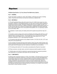
• To allow access to the fourth motherboard mounting screw,<br />
remove the 4–20 mA board by pulling up from the motherboard<br />
(see Figure 1), <strong>and</strong> put it out of harm’s way.<br />
• Unscrew the four Phillips (cross-head) screws holding the<br />
motherboard to the enclosure (see Figure 1). Remove the<br />
motherboard, <strong>and</strong> put it out of harm’s way.<br />
• Taking care to protect the User Interface board on the<br />
enclosure door, drill/punch entries as required (see Figure 2).<br />
Note: The <strong>TraceTek</strong> sensing circuit is power limited, so the<br />
<strong>TraceTek</strong> leader or jumper cable <strong>and</strong> the power supply cable<br />
must not run in the same conduit.<br />
• Fit conduit bushings/adapters.<br />
• Remove all traces of metal filings <strong>and</strong> dust from inside the<br />
module enclosure.<br />
Mount the module.<br />
The module mounts with four screws with mounting centers as<br />
noted in Figure 3. If plastic plugs are in the mounting holes, remove<br />
them. To seal around the mounting screw (necessary to maintain<br />
the NEMA 12 rating), use a rubber or elastomeric washer.<br />
Reassemble the module.<br />
Note: before replacing the motherboard, ensure that the interior<br />
of the enclosure is clean.<br />
• Replace the motherboard <strong>and</strong> secure it in place with the<br />
Phillips (cross-head) screws.<br />
• Replace the 4–20 mA board, taking care to align the<br />
connectors properly before applying pressure to seat the<br />
board. Markings on board should be right side up.<br />
• Reconnect the ribbon cable (taking care not to bend any pins<br />
in the connection).<br />
• To seal the bottom of the enclosure, put plastic plug (supplied in<br />
plastic bag with other small parts) into hole in bottom of enclosure.<br />
• Close <strong>and</strong> latch the door of the enclosure.<br />
2<br />
Figure 1<br />
Figure 2<br />
Figure 3<br />
9.45 in.<br />
(240 mm)<br />
0.79 in.<br />
(20 mm)<br />
7.87 in.<br />
(200 mm)<br />
Remove 4–20 mA board<br />
to gain access to fourth screw<br />
Remove screws attaching<br />
motherboard (four places)<br />
Area available for<br />
cable entries<br />
11.81 in.<br />
(300 mm)<br />
10.28 in.<br />
(261 mm)<br />
5⁄16 in. (7 mm) mounting hole<br />
(four places)<br />
Attachment point<br />
for motherboard<br />
(four places)<br />
Area<br />
available<br />
for cable<br />
entries<br />
0.79 in.<br />
(20 mm)