TraceTek Leak Detection and Location Module - California ...
TraceTek Leak Detection and Location Module - California ...
TraceTek Leak Detection and Location Module - California ...

Create successful ePaper yourself
Turn your PDF publications into a flip-book with our unique Google optimized e-Paper software.
R<br />
Product Information<br />
TTDM-1 115 Vac +15%, –20%; 50/60 Hz<br />
TTDM-2 230 Vac ±10%; 50/60 Hz<br />
TTDM-24 24 Vac +5%, –35% 24 Vdc ±20%<br />
Power consumption 6 VA (5 W) for TTDM-1 <strong>and</strong> TTDM-2<br />
12 VA (10 W) for TTDM-24<br />
Installation categories Overvoltage Category II<br />
(per IEC 664) Pollution Degree 2<br />
Relays Number: Three (Service, <strong>Leak</strong>, Fault)<br />
Type: DPDT<br />
Rating: 5 A at 250 Vac/24 Vdc<br />
Temperature Storage: 0°F to 140°F (–18°C to 60°C)<br />
Operating: 32°F to 122°F (0°C to 50°C)<br />
Enclosure NEMA 12; IP 54<br />
Approvals <strong>and</strong> Certifications<br />
LISTED<br />
76LJ<br />
SIGNAL SYSTEM UNIT<br />
The TTDM is approved for use in ordinary areas. The module must be<br />
located in an Ordinary Area, but may monitor intrinsically safe <strong>TraceTek</strong><br />
sensing cables located in Hazardous <strong>Location</strong>s:<br />
• <strong>TraceTek</strong> sensing cable in Class I, Division 2, Groups A, B, C, D<br />
Hazardous <strong>Location</strong>s<br />
• If protected by agency-approved zener barrier <strong>TraceTek</strong> sensing cable in<br />
Class I, Division 1, Groups A, B, C, D Hazardous <strong>Location</strong>s (Zone 0 or<br />
Zone 1 in Europe). Contact Raychem to select proper zener barrier.<br />
UL based their evaluation of the unit on UL St<strong>and</strong>ard 864. Since UL 864<br />
is intended for the evaluation of fire alarm control units, only certain<br />
requirements particular to the subject product’s use <strong>and</strong> construction were<br />
applicable. The system was evaluated for its inherent risk of fire <strong>and</strong> electric<br />
shock only. Its intended purpose is to detect <strong>and</strong> locate liquid leaks,<br />
not to serve as the primary means to prevent a critical process from<br />
becoming a risk of electric shock or creating a fire or other hazard.<br />
The module is compliant with IEC-801-2, 3, 4, 5.<br />
It meets the requirements of FCC, Part 15, Class B, <strong>and</strong> EN 55011-2 Class B.<br />
Additional items<br />
An agency-approved zener barrier must be used for cases where<br />
sensing cable connected to the TTDM will be located in a Class I,<br />
Division 1 (or Zone 0 or Zone 1 in Europe) Hazardous <strong>Location</strong>. A<br />
zener barrier also may be selected to provide lightning protection.<br />
1<br />
2<br />
4<br />
3<br />
5<br />
6<br />
F M<br />
APPROVED<br />
PRODUCT SERVICE<br />
geprüfte<br />
Sicherheit<br />
EUR • USA • JPN<br />
R <strong>TraceTek</strong><br />
TTDM<br />
Test<br />
Esc<br />
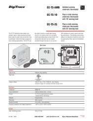
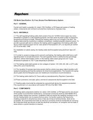
1 LCD display<br />
2 LEDs with icons<br />
3 Test key<br />
4 Silence key<br />
5 Reset key<br />
6 Menu keys<br />
Menu<br />
PL indicates power limited circuits<br />
Reset<br />
Enter<br />
WARNING: Shock hazard. Shut off power<br />
before opening enclosure door.<br />
24<br />
23<br />
7 User Interface board<br />
8 4–20 mA board<br />
9 Sensor Interface board<br />
10 Motherboard<br />
11 Power supply board<br />
12 Fuse (200 mA, 250 V)<br />
22<br />
1<br />
TTDM<br />
<strong>TraceTek</strong> <strong>Leak</strong> <strong>Detection</strong> <strong>and</strong><br />
<strong>Location</strong> <strong>Module</strong><br />
General Information<br />
Please read these instructions carefully <strong>and</strong> keep them in a safe<br />
place (preferably close to the module) for future reference.<br />
These instructions must be followed carefully to ensure proper<br />
operation.<br />
The TTDM Alarm <strong>and</strong> Locating <strong>Module</strong> has been designed<br />
specifically for use with <strong>TraceTek</strong> sensing cables (TT1000,<br />
TT3000, <strong>and</strong> TT5000 sensing cables <strong>and</strong> TT100, TT300, <strong>and</strong><br />
TT500 long-line sensing cables). The TTDM can monitor up to<br />
5000 ft (1500 m) of sensing cable, or 100 zones.<br />
The TTDM is designed for use in ordinary areas with temperatures<br />
of 32°F to 122°F (0°C to 50°C). The TTDM should be provided<br />
with branch circuit protection (no more than 20 A rating). A<br />
disconnect device should be included as part of the installation<br />
<strong>and</strong> marked as such; when a circuit breaker is used as a disconnect<br />
device, it should meet the relevant requirements of IEC<br />
947-1 <strong>and</strong> IEC 947-2. Follow all national <strong>and</strong> local codes applicable<br />
to the installation.<br />
Installation items (not supplied)<br />
• Wall fasteners for surface mounting (four screws)<br />
• Rubber or elastomeric washers to seal at mounting points<br />
Tools required<br />
• Drill or hole punch for electrical conduit entries<br />
• Phillips (cross-head) screwdriver<br />
• Small flat-head screwdriver<br />
Storage<br />
Keep the module in a dry place prior to installation to avoid possible<br />
damage to internal components.<br />
21<br />
7 8 9<br />
10<br />
PL PL PL<br />
20<br />
19<br />
PL<br />
18<br />
17<br />
13 Power cable terminal block<br />
14 Ground/earth stud<br />
15 Fault relay cable plug <strong>and</strong> socket<br />
16 <strong>Leak</strong> relay cable plug <strong>and</strong> socket<br />
17 Service relay cable plug <strong>and</strong> socket<br />
18 4–20 mA port plug <strong>and</strong> socket<br />
Installation Instructions<br />
16<br />
15<br />
11<br />
12<br />
13<br />
14<br />
19 RS-232/485 port plug <strong>and</strong> socket<br />
20 Sensing cable plug <strong>and</strong> socket<br />
21 Reserved for future use<br />
22 Ribbon cable<br />
23 Volume adjustment<br />
24 LCD contrast adjustment
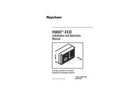
Installation Instructions for TTDM Alarm <strong>and</strong> Locating <strong>Module</strong><br />
Installing the TTDM<br />
Note: To avoid damage to the unit, store the TTDM module in its<br />
cardboard box until construction is complete.<br />
Select the mounting position.<br />
Choose a location indoors where the module will be protected from<br />
the elements <strong>and</strong> temperature extremes.<br />
WARNING: Ignition hazard. Do not mount the TTDM unit in<br />
a hazardous location. Sensing cable connected to the TTDM<br />
may (subject to approvals restrictions) be located in hazardous<br />
locations, but the module itself must be in an ordinary area.<br />
Prepare the module for mounting.<br />
Important: The TTDM is an electronic unit. During installation,<br />
take the following precautions to avoid damage to its electronic<br />
components:<br />
• H<strong>and</strong>le with care, avoid mechanical damage.<br />
• Keep the electronics dry.<br />
• If h<strong>and</strong>ling circuit boards, hold them by their edges to avoid<br />
physical contact with electronic components.<br />
• Avoid exposure to static electricity.<br />
• Avoid contamination with metal filings, liquids, or other<br />
foreign matter.<br />
• Remove the module from its carton. Do not remove the<br />
protective film from the membrane on the front of the unit.<br />
• Open the enclosure door using a flat-blade screwdriver or a coin.<br />
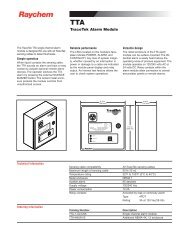
• Carefully disconnect the ribbon cable from the motherboard.<br />
• To allow access to the fourth motherboard mounting screw,<br />
remove the 4–20 mA board by pulling up from the motherboard<br />
(see Figure 1), <strong>and</strong> put it out of harm’s way.<br />
• Unscrew the four Phillips (cross-head) screws holding the<br />
motherboard to the enclosure (see Figure 1). Remove the<br />
motherboard, <strong>and</strong> put it out of harm’s way.<br />
• Taking care to protect the User Interface board on the<br />
enclosure door, drill/punch entries as required (see Figure 2).<br />
Note: The <strong>TraceTek</strong> sensing circuit is power limited, so the<br />
<strong>TraceTek</strong> leader or jumper cable <strong>and</strong> the power supply cable<br />
must not run in the same conduit.<br />
• Fit conduit bushings/adapters.<br />
• Remove all traces of metal filings <strong>and</strong> dust from inside the<br />
module enclosure.<br />
Mount the module.<br />
The module mounts with four screws with mounting centers as<br />
noted in Figure 3. If plastic plugs are in the mounting holes, remove<br />
them. To seal around the mounting screw (necessary to maintain<br />
the NEMA 12 rating), use a rubber or elastomeric washer.<br />
Reassemble the module.<br />
Note: before replacing the motherboard, ensure that the interior<br />
of the enclosure is clean.<br />
• Replace the motherboard <strong>and</strong> secure it in place with the<br />
Phillips (cross-head) screws.<br />
• Replace the 4–20 mA board, taking care to align the<br />
connectors properly before applying pressure to seat the<br />
board. Markings on board should be right side up.<br />
• Reconnect the ribbon cable (taking care not to bend any pins<br />
in the connection).<br />
• To seal the bottom of the enclosure, put plastic plug (supplied in<br />
plastic bag with other small parts) into hole in bottom of enclosure.<br />
• Close <strong>and</strong> latch the door of the enclosure.<br />
2<br />
Figure 1<br />
Figure 2<br />
Figure 3<br />
9.45 in.<br />
(240 mm)<br />
0.79 in.<br />
(20 mm)<br />
7.87 in.<br />
(200 mm)<br />
Remove 4–20 mA board<br />
to gain access to fourth screw<br />
Remove screws attaching<br />
motherboard (four places)<br />
Area available for<br />
cable entries<br />
11.81 in.<br />
(300 mm)<br />
10.28 in.<br />
(261 mm)<br />
5⁄16 in. (7 mm) mounting hole<br />
(four places)<br />
Attachment point<br />
for motherboard<br />
(four places)<br />
Area<br />
available<br />
for cable<br />
entries<br />
0.79 in.<br />
(20 mm)
Installation Instructions for TTDM Alarm <strong>and</strong> Locating <strong>Module</strong><br />
Connecting the Power Cable <strong>and</strong> Relays Testing the <strong>Module</strong><br />
Connect the power wiring.<br />
• Open door of TTDM enclosure.<br />
• Pass the power cable through the adapter/bushing.<br />
• Connect the ground/earth wire to the ground/earth stud.<br />
The ground/earth stud is marked with this symbol:<br />
Note: Proper grounding/earthing is important to avoid<br />
the possibility of electromagnetic interference.<br />
Note: Ground/earth wire must be longer than the other two<br />
conductors for strain relief.<br />
• Connect the power supply wires to the two-pin terminal block on<br />
the power supply board. Use L2 for neutral, if present.<br />
Note: The terminals can accept wires 10 AWG (4.7 sq. mm) or<br />
smaller. We recommend 12 AWG (3.0 sq. mm) wires, with branch<br />
circuit protection sized accordingly. Cable should have a<br />
temperature rating of 65°C.<br />
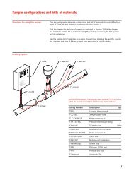
Connect the alarm relays.<br />
The TTDM has three relays, for service, leak, <strong>and</strong> fault. Each relay<br />
provides two Form-C relay contacts, <strong>and</strong> normally open <strong>and</strong> normally<br />
closed contacts are both provided. The relays are de-energized<br />
to indicate an alarm condition. The illustration below shows the<br />
relay status when in the alarm (de-energized) state.<br />
The illustrations that follow show how relays can be jumpered<br />
together to allow remote monitoring of the TTDM status with only a<br />
single pair of wires. The TTDM de-energizes its relays to signal an<br />
alarm condition. Therefore, loss of power, as well as any other type<br />
of alarm, would trip the remote alarm.<br />
SERVICE RELAY<br />
LEAK RELAY<br />
5A 250V<br />
5A 250V<br />
1 J6<br />
1 J25<br />
1<br />
NC NO COM NC NO COM<br />
15<br />
16<br />
17<br />
18<br />
19<br />
20<br />
Alarm on closed circuit<br />
SERVICE RELAY<br />
LEAK RELAY<br />
5A 250V<br />
5A 250V<br />
1 J6<br />
1 J25<br />
1<br />
NC NO COM NC NO COM<br />
15<br />
16<br />
17<br />
18<br />
19<br />
20<br />
Do not exceed<br />
maximum voltage<br />
rating.<br />
SERVICE RELAY LEAK RELAY FAULT RELAY<br />
15 16 17 18 19 20 21 22 23 24 25 26 27 28 29 30 31 32<br />
Alarm on open circuit<br />
NC NO COM NC NO COM<br />
21<br />
22<br />
23<br />
24<br />
25<br />
26<br />
NC NO COM NC NO COM<br />
21<br />
22<br />
23<br />
24<br />
25<br />
26<br />
FAULT RELAY<br />
5A 250V<br />
J9<br />
NC NO COM NC NO COM<br />
27<br />
28<br />
29<br />
30<br />
31<br />
32<br />
FAULT RELAY<br />
5A 250V<br />
J9<br />
NC NO COM NC NO COM<br />
27<br />
28<br />
29<br />
30<br />
31<br />
32<br />
L1<br />
L2<br />
38<br />
39<br />
Use for neutral,<br />
if present.<br />
VAC IN<br />
Relays wired<br />
in series<br />
Monitoring circuit<br />
(alarm on open circuit)<br />
Relays wired<br />
in parallel<br />
Monitoring circuit<br />
(alarm on closed circuit)<br />
Note: The relay plugs can accept wires 10 AWG (4.7 sq. mm) or<br />
smaller. We recommend 18 AWG (1.0 sq. mm) wires. Cable should<br />
have a temperature rating of 65°C.<br />
Note: Maximum load for relays is 5 A.<br />
3<br />
Test after supplying power.<br />
• Close <strong>and</strong> latch the enclosure door.<br />
• Supply power to the unit. When power is supplied, the green LED<br />
illuminates, <strong>and</strong> the unit goes through a series of self-tests. After<br />
the start-up sequence is complete, the module should report a fault<br />
alarm (this is normal; there is no sensing cable attached). Press<br />
the red Silence key to silence the audible alarm. Verify that the display<br />
appears as shown below (but with different time <strong>and</strong> date):<br />
Cable Break<br />
14:23 02-Jan-96<br />
If anything other than the above occurs, check all connections.<br />
If unit still does not appear to operate properly, contact a<br />
Raychem <strong>TraceTek</strong> representative for assistance.<br />
• Press the Test button. The module conducts a number of<br />
self-tests.<br />
• If the tests are successfully completed, record this on the<br />
installation record.<br />
• Interrupt the power supply to the unit.<br />
Test with TTDM test plug.<br />
• To conduct a more complete test, use the <strong>TraceTek</strong> TTDM-CTP<br />
test plug (packed in a plastic bag in the TTDM packaging). Insert<br />
the plug into the sensing cable socket; align it with the four color<br />
coded pins.<br />
• Close <strong>and</strong> latch the enclosure door.<br />
• Supply power to the unit. When power is supplied, the unit will<br />
again go through a series of self-tests. If the test plug is in the<br />
sensing cable socket, after the module completes the start-up<br />
sequence it should sound <strong>and</strong> display a leak alarm. Press the<br />
Silence key to silence the audible alarm. The red <strong>Leak</strong> LED <strong>and</strong><br />
green Monitoring LED should both be illuminated, <strong>and</strong> the screen<br />
display should appear as shown below (depending on the setting):<br />
<strong>Leak</strong> 538 ft<br />
14:37 02-Jan-96<br />
If ft: 538 ± 11<br />
If m: 164 ± 4<br />
If zones: 11<br />
• If anything other than the above occurs, check all connections. If<br />
unit still does not appear to operate properly, contact a Raychem<br />
<strong>TraceTek</strong> representative for assistance.<br />
• If the test is successfully completed, record this on the<br />
installation record.<br />
• Interrupt the power supply to the unit.<br />
• Remove the TTDM test plug <strong>and</strong> store it in a secure place for<br />
future use.<br />
• If not immediately connecting the sensing cable, close <strong>and</strong> latch<br />
the enclosure.
Installation Instructions for TTDM Alarm <strong>and</strong> Locating <strong>Module</strong><br />
Connecting the Sensing Cable Start-Up <strong>and</strong> System Testing<br />
Prepare sensing cable.<br />
Ensure that the sensing cable has been installed <strong>and</strong> tested in<br />
accordance with the instructions provided with the cable.<br />
Make connections.<br />
• Confirm that power to the unit has been shut off.<br />
• Open the enclosure door.<br />
• Feed the end of the <strong>TraceTek</strong> Modular Leader Cable (or Jumper<br />
Cable) through the adapter/bushing.<br />
• Connect the four color-coded wires to the Sensor Interface plug.<br />
Important: Observe the color coding. If wires are not connected<br />
to the proper terminals, the leak detection system cannot operate<br />
properly.<br />
• Insert the sensing cable (SI) plug into the SI socket (item 20 on<br />
the product illustration on the first page).<br />
Install zener barrier, if applicable.<br />
When sensing cable will be located in Class I, Division 1 locations,<br />
approval agencies require that the sensing cable be protected<br />
with a zener barrier between the sensing cable <strong>and</strong> the<br />
TTDM module. A zener barrier may also be used to provide<br />
lightning protection for the module when the sensing cable may<br />
be exposed to electrical discharges. Contact Raychem to select<br />
the proper zener barrier.<br />
When installing a zener barrier, wire it in accordance with the<br />
instructions provided with the kit.<br />
TTDM<br />
Ordinary Area<br />
Zener<br />
barrier<br />
Leader or jumper cable<br />
RED GRN YEL BLK AGND<br />
33<br />
34<br />
35<br />
36<br />
37<br />
SENSOR CABLE<br />
PL<br />
Class I, Division 1<br />
(Zone 0 or Zone 1 in Europe)<br />
Hazardous <strong>Location</strong><br />
//// / / / / / / / / / / / / / / / / / / / / / / / / / ///////////// / / / / / / / / / / / / / / / ///////////// / / / / / / / / / / / / / / / / //////////// / / / /<br />
Jumper cable<br />
No connection<br />
to terminal 37<br />
Sensing cable<br />
Connecting the Interfaces<br />
If connecting the 4–20 mA port or the RS-232/RS-485 serial<br />
port, refer to the <strong>TraceTek</strong> TTDM Operation <strong>and</strong> Maintenance<br />
Manual for details.<br />
R<br />
Belgium<br />
NV Raychem SA<br />
Diestsesteenweg 692<br />
3010 Kessel-Lo<br />
Tel (32) 16/351-800<br />
Fax (32) 16/351-797<br />
Korea<br />
Raychem Korea Limited<br />
831-45 Yeuksam-Dong<br />
Kangnam-Ku<br />
Seoul 135<br />
Tel (82) 2/557-7752<br />
Fax (82) 2/558-5765<br />
4<br />
Power up the system.<br />
After connections are complete, supply power to the unit. The<br />
unit will go through a series of self-tests, <strong>and</strong> then display the<br />
system status. If the sensing circuit is complete <strong>and</strong> free of leaks<br />
or other problems, the green Monitoring LED only will illuminate,<br />
<strong>and</strong> the LCD display will appear as follows:<br />
System Normal<br />
16:23 02-Jan-96<br />
If this is not the case, you can find additional information in the<br />
TTDM Operation <strong>and</strong> Maintenance Manual supplied with the<br />
module.<br />
Commissioning<br />
Your system should be commissioned by an authorized<br />
<strong>TraceTek</strong> representative. The system map is a crucial part of a<br />
<strong>TraceTek</strong> locating system. The TTDM will give the point along<br />
the sensing cable at which liquid has been detected; the map is<br />
essential to show its physical location.<br />
Important: Store hardware <strong>and</strong> documentation supplied with<br />
the TTDM in a secure place for later use (commissioning,<br />
connecting interfaces, operating).<br />
United Kingdom<br />
Raychem Ltd.<br />
Faraday Road<br />
Dorcan, Wiltshire SN3 5HH<br />
Tel (44) 1793/572-663<br />
Fax (44) 1793/572-629<br />
United States<br />
Raychem Corporation<br />
Commercial & Industrial<br />
Infrastructure Division<br />
300 Constitution Drive<br />
Menlo Park, CA 94025-1164<br />
Tel (800) 545-6258<br />
Fax (800) 611-2323<br />
© 1996 Raychem Corporation Printed in USA H55471 P/N 261985 4/96 <strong>TraceTek</strong> is a trademark of Raychem Corporation.