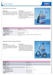
“QD” BUSHING
“QD” BUSHING
“QD” BUSHING

Create successful ePaper yourself
Turn your PDF publications into a flip-book with our unique Google optimized e-Paper software.
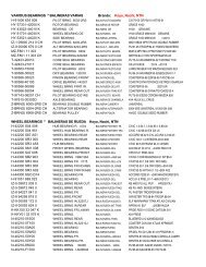
<strong>BUSHING</strong>S & HUBS<br />
TAPER-LOCK <strong>BUSHING</strong>S<br />
DIMENSIONS FOR 1008 THRU 5050<br />
Bushing<br />
Size<br />
19<br />
Rating •<br />
Torque<br />
Capacity<br />
(lb - in.)<br />
Hub Diam. Ref. Installation Screw +<br />
A B C D Qty Size<br />
Gray Iron<br />
G<br />
Std<br />
Hex<br />
Key<br />
L * M *<br />
Short<br />
Key<br />
€<br />
Std<br />
Hex<br />
Key<br />
Short<br />
Key<br />
€<br />
Approx.<br />
Wt.<br />
(lbs)<br />
1008 1,200 1 3/8 7/8 2 3/16 1 21/64 2 1/4 x1/2 1 1/8 5/8 1 1/4 3/4 0.2<br />
1108 1,300 1 1/2 7/8 2 5/16 1 29/64 2 1/4 x1/2 1 1/8 5/8 1 1/4 3/4 0.2<br />
1210 3,600 1 7/8 1 3 1/4 1 3/4 2 3/8 x 5/8 1 3/8 13/16 1 5/8 1 1/16 0.5<br />
1215 3,550 1 7/8 1 1/2 2 7/8 1 3/4 2 3/8 x 5/8 1 3/8 13/16 1 5/8 1 1/16 0.3<br />
1310 3,850 2 1 3 3/8 1 7/8 2 3/8 x 5/8 1 3/8 13/16 1 5/8 1 1/16 0.6<br />
1610 4,300 2 1/4 1 3 5/8 2 1/8 2 3/8 x 5/8 1 3/8 13/16 1 5/8 1 1/16 0.7<br />
1615 4,300 2 1/4 1 1/2 3 1/4 2 1/8 2 3/8 x 5/8 1 3/8 1 3/16 1 5/8 1 11/16 1.0<br />
2012 7,150 2 3/4 1 1/4 4 3/8 2 5/8 2 7/16 x 7/8 1 9/16 15/16 2 1 3/8 1.4<br />
2517 11,600 3 3/8 1 3/4 4 7/8 3 1/4 2 1/2 x 1 1 5/8 1 2 1/4 1 5/8 3.1<br />
2525 11,300 3 3/8 2 1/2 4 1/2 3 1/4 2 1/2 x 1 1 5/8 1 2 1/4 1 5/8 3.5<br />
3020 24,000 4 1/4 2 6 1/4 4 2 5/8 x 1 1/4 1 13/16 1 3/16 2 11/16 2 1/16 5.0<br />
3030 24,000 4 1/4 3 5 3/4 4 2 5/8 x 1 1/4 1 13/16 1 3/16 2 11/16 2 1/16 7.4<br />
3535 44,800 5 3 1/2 7 4 27/32 3 1/2 x 1 1/2 39 2 1 5/16 3 3/8 2 11/16 9.8<br />
4040 77,300 5 3/4 4 8 1/2 5 35/64 3 5/8 x 1 3/4 40 2 3/8 1 5/8 4 1/8 3 3/8 15.4<br />
4545 110,000 6 3/8 4 1/2 9 1/2 6 1/8 3 3/4 x 2 40 2 5/8 1 15/16 4 3/4 4 1/16 21.0<br />
5050 126,000 7 5 10 1/2 6 23/32 3 7/8 x 2 1/4 37 2 13/16 2 5/16 5 1/4 4 13/16 29.0<br />
+ Use in position shown in drawing above for tightening bushing on shaft. When loosening bushing, remove screws and use<br />
all except one in the other holes.<br />
* Space required to remove bushing using jackscrews - no puller required.<br />
€ Standard hex key cut to minimum useable length.<br />
• Peak torque loads must not exceed torque capacity rating shown. Capacity values shown are for light starting and steady<br />
running conditions. For more severe duty, divide torque capacity by service factor suggested in table below.<br />
Note: Approx. weight in lbs. for an average size bore.<br />
SERVICE FACTOR<br />
Service Factor Type of Loading<br />
1.0 Light starting & steady running<br />
1.5 Light starting & uneven running<br />
2.0 Fairly heavy starting & steady or uneven running<br />
2.5 Light or heavy starting & moderate shock running<br />
3.0 Light or heavy starting & severe shock running, or reversing loads<br />
FOR DEPENDABLE DRIVE COMPONENTS,