
Create successful ePaper yourself
Turn your PDF publications into a flip-book with our unique Google optimized e-Paper software.
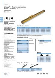
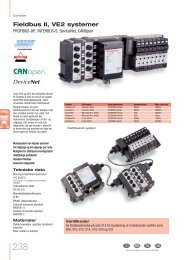
Actuators<br />
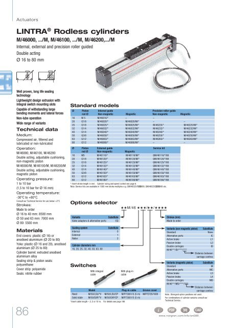
LINTRA ® Rodless cylinders<br />
M/<strong>46000</strong>, .../M, M/46100, .../M, M/46200,.../M<br />
Internal, external and precision roller guided<br />
Double acting<br />
Ø 16 to 80 mm<br />
Well proven, long life sealing<br />
technology<br />
Lightweight design extrusion with<br />
integral switch mounting slots<br />
Capable of withstanding large<br />
bending moments and lateral forces<br />
Non-lube operation<br />
Wide range of variants<br />
Technical data<br />
Medium:<br />
Compressed air, filtered and<br />
lubricated or non-lubricated<br />
Operation:<br />
M/<strong>46000</strong>, M/46100, M/46200<br />
Double acting, adjustable cushioning,<br />
non-magnetic piston<br />
M/<strong>46000</strong>/M, M/46100/M, M/46200/M<br />
Double acting, adjustable cushioning,<br />
magnetic piston<br />
Operating pressure:<br />
1 to 10 bar<br />
(1,5 to 10 bar for Ø 16 mm)<br />
Operating temperature:<br />
-30°C to +80°C.<br />
Consult our Technical Service for use below +2°C<br />
Strokes:<br />
Made to order<br />
Ø 16 to 40 mm: 8500 mm<br />
Ø 50 and 63 mm: 7000 mm<br />
Ø 80: 5500 mm<br />
Materials<br />
End covers: plastic (Ø 16) or<br />
anodised aluminium (Ø 20 to 80)<br />
Yoke: plastic (Ø 16 and 20), anodised<br />
aluminium (Ø 25 to 80)<br />
Cylinder barrel: extruded anodised<br />
aluminium alloy<br />
Sealing strip & piston seals:<br />
polyurethane<br />
Cover strip: polyamide<br />
Seals: nitrile rubber<br />
86<br />
Standard models<br />
Ø Piston Internal guide<br />
Precision roller guide<br />
rod Ø Non-magnetic Magnetic<br />
Non-magnetic Magnetic<br />
16 M 5 M/46016/M/* M/46016/*<br />
– –<br />
20 G1/8 M/46020/*<br />
M/46020/M/* – –<br />
25 G1/8 M/46025/*<br />
M/46025/M/* M/46225/* M/46225/M/*<br />
32 G1/4 M/46032/*<br />
M/46032/M/* M/46232/* M/46232/M/*<br />
40 G1/4 M/46040/*<br />
M/46040/M/* M/46240/* M/46240/M/*<br />
50 G3/8 M/46050/*<br />
M/46050/M/* M/46250/* M/46250/M/*<br />
63 G1/2 M/46063/*<br />
M/46063/M/* M/46263/* M/46263/M/*<br />
80 G1/2 M/46080/*<br />
M/46080/M/* – –<br />
Ø Piston External guide<br />
Service kit<br />
rod Ø Non-magnetic Magnetic<br />
16 M5 M/46116/* M/46116/M/* QM/46116/*/88<br />
20 G1/8 M/46120/* M/46120/M/* QM/46120/*/88<br />
25 G1/8 M/46125/* M/46125/M/* QM/46125/*/88<br />
32 G1/4 M/46132/* M/46132/M/* QM/46132/*/88<br />
40 G1/4 M/46140/* M/46140/M/* QM/46140/*/88<br />
50 G3/8 M/46150/* M/46150/M/* QM/46150/*/88<br />
63 G1/2 M/46163/* M/46163/M/* QM/46163/*/88<br />
80 G1/2 M/46180/* M/46180/M/* QM/46180/*/88<br />
* Insert stroke length in mm. Cylinder sizing and speed control see page 6.<br />
Note: Service kits are available in 1000 mm stroke multiples e.g. QM/46025/1000/88, QM/46025/2000/88 etc.<br />
Options selector ˙˙M/46 ˙˙˙/˙˙/˙˙˙˙<br />
Variants Substitute<br />
Valve adaptors & alternative ports EQ<br />
Guiding system Substitute<br />
Internal 0<br />
External 1<br />
Roller 2<br />
Cylinder diameters mm<br />
16, 20, 25, 32, 40, 50, 63, 80<br />
Switches<br />
With integral<br />
cable<br />
*Insert cable length – 2, 5 or 10 m. For details see page 198<br />
With plug-in<br />
cable<br />
Model Plug-in cable Groove cover<br />
Reed M/50/LSU/*V M/50/LSU/CP M/P73001/5 (5 m) M/P72725/1000<br />
Solid state M/50/EAP/*V M/50/EAP/CP M/P73001/5 (5 m)<br />
Strokes (mm)<br />
Made to order<br />
Variants (non-magnetic piston) Substitute<br />
Standard None<br />
Alternative ports IC<br />
Active brake L1<br />
Passive brake L2<br />
Double carriages ID<br />
M/46***/ID/****/****<br />
Distance between<br />
carriage centres<br />
Variants (magnetic piston) Substitute<br />
Standard M<br />
Alternative ports MC<br />
Active brake L3<br />
Passive brake L4<br />
Double carriages MD<br />
M/46***/MD/****/****<br />
Distance between<br />
carriage centres<br />
Note: Disregard option positions not used.<br />
For combinations of cylinder variants consult our<br />
Technical Service.<br />
www.norgren.com/info/en086
Mountings<br />
Ø C S* UV* V W*** UW ***<br />
16 QM/46016/21 QM/46016/37 QM/46016/34 QM/46016/32 QM/46116/35 – – – M/P72816<br />
20 QM/46020/21 QM/46020/37 QM/46020/34 QM/46020/32 QM/46120/35 QM/46120/36 – – M/P72816<br />
25 QM/46025/21 QM/46025/37 QM/46025/34 QM/46025/32 QM/46125/35 QM/46125/36 QM/46125/67 – M/P72816<br />
32 QM/46032/21 QM/46032/37 QM/46032/34 QM/46032/32 QM/46132/35 QM/46132/36 QM/46132/67 – M/P72816<br />
40 QM/46040/21 QM/46032/37 QM/46040/34 QM/46040/32 QM/46140/35 QM/46140/36 QM/46140/67 M/P41434 M/P72816<br />
50 QM/46050/21 QM/46050/37 QM/46050/34 QM/46050/32 QM/46150/35 QM/46150/36 QM/46150/67 M/P41435 M/P72816<br />
63 QM/46063/21 QM/46050/37 QM/46063/34 QM/46063/32 QM/46163/35 QM/46163/36 QM/46163/67 M/P41436 M/P72816<br />
80 QM/46080/21 QM/46080/37 QM/46080/34 QM/46080/32 QM/46180/35 – QM/46180/67 – M/P72816<br />
Please see page 93 for details of mountings.<br />
* Suitable for internally guided models only, ** Insert stroke length (mm), *** Suitable for external guided models only.<br />
# Suitable for external and precision roller guided models only.<br />
# For use with switches M/50, see page 198<br />
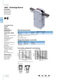
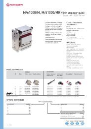
Standard cylinders<br />
M/<strong>46000</strong>, M/<strong>46000</strong>/M – Cylinders with internal guide<br />
*For cylinder Ø 80 mm<br />
2 x A + stroke<br />
stroke<br />
M/46100, M/46100/M – Cylinders with external guide<br />
Cushion screw<br />
LINTRA ® Rodless cylinders<br />
M/<strong>46000</strong>, .../M, M/46100, .../M, M/46200, .../M<br />
Internal, external and precision roller guided<br />
Double acting<br />
Ø 16 to 80 mm<br />
Assembly kit<br />
for shock<br />
absorbers#<br />
Section A - B<br />
for Ø 20 to 80 mm<br />
Plate for<br />
shock<br />
absorbers<br />
Section A - B<br />
for Ø 16 mm<br />
Groove key<br />
Ø A AB AC AE AG AO B C D E F G J K L M N<br />
16 62,5 – 7,0 38 8 (7,5) 17,5 8 M5 80 60 – 2,5 (–) Ø 3 G7 31 18 M3<br />
20 85 – (60) 14 (–) 54 (59) 18 (6,5) 23 8 G1/8 110 80 40 3,5 (7,5) Ø 4,2H9 42 27 (Ø 5,5) M5<br />
25 100 – (70) 12 (–) 60 (67,5) 20 (9,5) 23 14,5 G1/8 130 90 45 – (5) … 4,5 52 32 (Ø 5,5) M5<br />
32 120 – (90) 16 (–) 76 (82) 25 (15,5) 27 10,5 G1/4 160 120 60 – (5) … 6 64 45 (Ø 5,5) M5<br />
40 150 – (120) 15 (–) 90 (97,5) 25 (16,5) 30 11,5 G1/4 215 160 80 – (5) … 6 79 45 (Ø 6,6) M6<br />
50 180 – (160) 20 (–) 110 (117) 25 (24) 35 14 G3/8 250 190 95 – (6,5) … 8 92 50 (Ø 9) M8<br />
63 215 – (190) 20 (–) 125 (137) 25 (25,5) 40 17 G1/2 320 240 120 – (7,5) … 8 110 50 (Ø 9) M8<br />
80 260 240 24 (–) 154 (165) 25 (38) 45 17 G1/2 390 300 150 9 (10) Ø 12G7 130 50 M10<br />
Ø O O1 P P1 R R1 R2 S S1 T Ø U W Y Z kg at 0 mm kg per 100 mm<br />
16 25 32 12 (–) – 27 31 (18,5) 16 5,5 M3x5 deep – – 4 (5) 16,5 0,16 0,10<br />
20 32 38 18,5 (–) – 40 40 (24) 32 4 M5x12 deep – – 12 21,5 0,50 0,15<br />
25 40 45 16 (–) 7,5 48 48 (34) 37 5,5 M5x13 deep – 33 7 (12) 17 0,80 0,20<br />
32 52 52 20 (–) 10 60 60 (42,5) 47 6,5 M6x17 deep – 40 8 (12) 20 1,60 0,35<br />
40 65 65 20 (–) 10 75 75 (49,5) 58 8,5 M8x20 deep – 50 8 (12) 25 2,70 0,50<br />
50 80 80 25 (–) 13 90 90 (58,5) 70 10 M8x18 deep – 60 11 (17) 30 4,80 0,75<br />
63 95 95 25 (–) 14 105 105 (68) 84 10,5 M10x25 deep – 70 11 (20) 35 7,20 1,00<br />
80 120 120 29 (–) – 130 130 (81 ) 100 15 M12x26 deep 11 90 15 (25) 40 13,2 1,50<br />
( ) for external guided<br />
87
Actuators<br />
LINTRA ® Rodless cylinders<br />
M/<strong>46000</strong>, .../M, M/46100, .../M, M/46200, .../M<br />
Internal, external and precision roller guided<br />
Double acting<br />
Ø 16 to 80 mm<br />
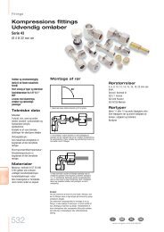
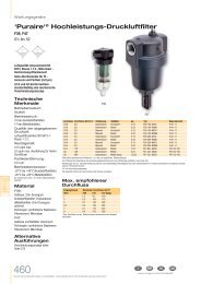
M/46200, M/46200/M – Cylinders with precision roller guide<br />
Ø A1 CA CB CC CD CE CF CG CH E<br />
kg at 0 mm kg per 100 mm<br />
25 100 45 90 M6x14 deep 36 42 66 60 85 150 1,70 0,20<br />
32 120 60 120 M8x16 deep 38 50 80 75 98 180 3,10 0,35<br />
40 150 80 150 M8x16 deep 42 57,5 95 92 118 215 5,00 0,50<br />
50 180 90 180 M10x20 deep 44 67 112 100 132 250 9,10 0,75<br />
63 215 120 240 M10x20 deep 47 74,5 127 110 140 320 13,9 1,00<br />
For full cylinder dimensions refer to page. 87<br />
Cylinder variants<br />
M/<strong>46000</strong>/IC, M/<strong>46000</strong>/MC, M/46100/IC, M/46100/MC, M/46200/IC, M/46200/MC – Cylinders with alternative ports<br />
Ø A B C D W X Z<br />
25 100 23 14,5 G 1/8 33 33 17<br />
32 120 27 10,5 G 1/4 40 34,5 20<br />
40 150 30 11,5 G 1/4 50 43,5 25<br />
50 180 35 14 G 3/8 60 53,5 30<br />
63 215 40 17 G 1/2 70 61,5 35<br />
For full cylinder dimensions refer to page. 87<br />
88<br />
2 x A + stroke<br />
* Alternative ports with inserted plugs.<br />
stroke<br />
2 x A + stroke<br />
stroke
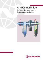
EQM/<strong>46000</strong>, EQM/<strong>46000</strong>/M, EQM/46100, EQM/46100/M, EQM/46200, EQM/46200/M – Cylinders with valve adaptors and alternative ports<br />
(Order the Excel valves, model V05X486M-B63*A, see page 310)<br />
2 x A1 + stroke<br />
Ø A1 D1 … R S S1 T W1<br />
25 132 G 1/8 48 37 5,5 M 5 x 13 deep 33<br />
32 152 G 1/8 60 47 6,5 M 6 x 15 deep 34,5<br />
40 182 G 1/8 75 58 8,5 M 8 x 20 deep 43,5<br />
50 212 G 1/8 90 70 10 M 8 x 25 deep 53,5<br />
63 247 G 1/8 105 84 10,5 M 10 x 25 deep 61,5<br />
For full cylinder dimensions refer to page 87<br />
M/46100/ID, M/46100/MD – Cylinders with external guide and double carriage<br />
+ stroke<br />
Ø A E X min. X max.<br />
16 62,5 80 80 500<br />
20 85 110 110 500<br />
25 100 130 130 500<br />
32 120 160 160 500<br />
40 150 215 215 500<br />
50 180 250 250 500<br />
63 215 320 320 500<br />
80 260 390 390 500<br />
To order an externally guided cylinder with double carriages, Ø 50 mm and 500 mm stroke, non-magnetic, dimension ‘X’ = 200 mm. Quote: M/46150/ID/500/200<br />
For full cylinder dimensions refer to page. 87<br />
stroke<br />
LINTRA ® Rodless cylinders<br />
M/<strong>46000</strong>, .../M, M/46100, .../M, M/46200, .../M<br />
Internal, external and precision roller guided<br />
Double acting<br />
Ø 16 to 80 mm<br />
M 4 x 7 deep<br />
View B<br />
89
Actuators<br />
LINTRA ® Rodless cylinders<br />
M/<strong>46000</strong>, .../M, M/46100, .../M, M/46200, .../M<br />
Internal, external and precision roller guided<br />
Double acting<br />
Ø 16 to 80 mm<br />
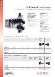
QM/46100/33 and QM/46200/35 – Right angle mounting system<br />
A1 + stroke<br />
For full dimensions see page 87<br />
Load values: For QM/<strong>46000</strong>/*/33 see basic cylinders M/46100, for QM/46200/*/35 see basic cylinders M/46200.<br />
Right angle mounting system externally guided<br />
Ø Model (Non-magnetic) Model (Magnetic) Right angle adaptor A1 + stroke A2 + stroke LA LB LC LD<br />
25 QM/46025/*/33 QM/46025/M/*/33 QM/46125/25/33 100 100 69 117 130 130<br />
25 QM/46025/*/33 QM/46025/M/*/33<br />
32 QM/46032/*/33 QM/46032/M/*/33 QM/46132/32/33 120 120 84 144 160 160<br />
32 QM/46032/*/33 QM/46032/M/*/33<br />
40 QM/46040/*/33 QM/46040/M/*/33 QM/46140/40/33 150 150 97 172 215 215<br />
40 QM/46040/*/33 QM/46040/M/*/33<br />
50 QM/46050/*/33 QM/46050/M/*/33 QM/46150/50/33 180 180 116 206 250 250<br />
50 QM/46050/*/33 QM/46050/M/*/33<br />
* Insert stroke length. To order right angle mounting system for same size cylinders, style ‘X’, order two cylinders of the same bore size together with one right angle adaptor, e.g. 2 off QM/46040/*/33 and 1 off QM/46140/40/33.<br />
Same size cylinder system style ‘X’<br />
Ø Model (Non-magnetic) Model (Magnetic) Right angle adaptor A1 + stroke A2 + stroke LA LB LC LD<br />
25 QM/46025/*/33 QM/46025/M/*/33 QM/46125/20/33 100 85 62 105,5 130 110<br />
20 QM/46020/*/33 QM/46020/M/*/33<br />
32 QM/46032/*/33 QM/46032/M/*/33 QM/46132/25/33 120 100 76,5 130,5 160 130<br />
25 QM/46025/*/33 QM/46025/M/*/33<br />
* Insert stroke length. To order a 1st reduction right angle mounting system for cylinders of the next bore size smaller, style ‘X1’, order two cylinders of successive bore sizes together with one right angle adaptor, e.g. 1 off<br />
QM/46025/*/33, 1 off QM/46020/*/33 and 1 off QM/46125/20/33.<br />
1st Reduction system style ‘X1’<br />
Ø Model (Non-magnetic) Model (Magnetic) Right angle adaptor A1 + stroke A2 + stroke LA LB LC LD<br />
40 QM/46040/*/33 QM/46040/M/*/33 QM/46140/25/33 150 100 77 138,5 215 130<br />
25 QM/46025/*/33 QM/46025/M/*/33<br />
50 QM/46050/*/33 QM/46050/M/*/33 QM/46150/32/33 180 120 94 169 250 160<br />
32 QM/46032/*/33 QM/46032/M/*/33<br />
63 QM/46063/*/33 QM/46063/M/*/33 QM/46163/40/33 215 150 108 198 320 215<br />
40 QM/46040/*/33 QM/46040/M/*/33<br />
* Insert stroke length. To order a 2nd reduction right angle mounting system for cylinders two bore sizes smaller, style ‘X2’, order two cylinders of successive bore sizes together with one right angle adaptor, e.g. 1 off<br />
QM/46040/*/33, 1 off QM/46025/*/33 and 1 off QM/46140/25/33.<br />
Right angle mounting system precision roller guided<br />
2nd Reduction system style ‘X2’<br />
Ø Model (Non-magnetic) Model (Magnetic) Right angle adaptor A1 + stroke A2 + stroke LA LB LC LD<br />
40 QM/46240/*/35 QM/46240/M/*/35 QM/46240/25/35 150 100 80 141,5 215 130<br />
25 QM/46225/*/35 QM/46225/M/*/35<br />
63 QM/46263/*/35 QM/46263/M/*/35 QM/46263/40/35 215 150 108 198 320 215<br />
40 QM/46240/*/35 QM/46240/M/*/35<br />
* Insert stroke length. To order a 2nd reduction right angle mounting system for cylinders two bore sizes smaller, style ‘X2’, order two cylinders of successive bore sizes together with one right angle adaptor, e.g. 1 off<br />
QM/46240/*/35, 1 off QM/46225/*/35 and 1 off QM/46240/25/35.<br />
90<br />
A2 + stroke