85-Ton Power Swivel Instruction Manual - Logan Oil Tools
85-Ton Power Swivel Instruction Manual - Logan Oil Tools
85-Ton Power Swivel Instruction Manual - Logan Oil Tools

Create successful ePaper yourself
Turn your PDF publications into a flip-book with our unique Google optimized e-Paper software.
<strong>85</strong>-<strong>Ton</strong> <strong>Power</strong> <strong>Swivel</strong>
contents<br />
Overview................................................................................2<br />
Uses ......................................................................................2<br />
Important Safety Information .................................................2<br />
Construction ..........................................................................3<br />
<strong>Power</strong> <strong>Swivel</strong> Assembly .....................................................3<br />
Control Units ......................................................................3<br />
Basic <strong>Power</strong> System ..........................................................4<br />
Hydraulic System ...............................................................4<br />
<strong>Power</strong> Unit .........................................................................4<br />
Trailer-Mounted Unit .......................................................4<br />
Skid-Mounted Unit ..........................................................4<br />
Containerized Unit ..........................................................5<br />
Installation .............................................................................5<br />
Rig Up ................................................................................5<br />
Pre-Operation Start-up Procedures ...................................5<br />
Electric Controls .............................................................5<br />
Air Controls.....................................................................5<br />
Operation ...............................................................................6<br />
General Rules ....................................................................6<br />
Air Controls ........................................................................6<br />
Electric Controls .................................................................6<br />
Maintenance ..........................................................................6<br />
<strong>Power</strong> <strong>Swivel</strong> Maintenance ................................................7<br />
Lubrication .........................................................................7<br />
Breaking-In .....................................................................7<br />
Storage ...........................................................................7<br />
Replacing the Floating Washpipe Assembly<br />
and Packing................................................................7<br />
<strong>Power</strong> Unit Maintenance ....................................................7<br />
Engine ............................................................................7<br />
Hydraulic <strong>Oil</strong> and Filters .................................................7<br />
Filters ..............................................................................7<br />
Hoses .............................................................................7<br />
<strong>Power</strong> Unit ......................................................................9<br />
<strong>Power</strong> Units With Air Controls ........................................9<br />
<strong>Power</strong> Units With Electric Controls.................................9<br />
<strong>Power</strong> <strong>Swivel</strong> ..................................................................9<br />
<strong>Swivel</strong> Disassembly ...............................................................9<br />
<strong>Swivel</strong> Reassembly .............................................................16<br />
Troubleshooting ...................................................................18<br />
Specifications ......................................................................19<br />
<strong>Power</strong> <strong>Swivel</strong> Performance Data .........................................20<br />
1 • <strong>Logan</strong> <strong>85</strong>-<strong>Ton</strong> <strong>Power</strong> <strong>Swivel</strong><br />
Drawings and Schematics<br />
Floating Washpipe Assembly ................................................8<br />
<strong>Swivel</strong> Head Assembly:<br />
Front View ........................................................................12<br />
Side View .........................................................................13<br />
Top View ..........................................................................14<br />
Section A-A – Through Gear Train) ..................................15<br />
<strong>Swivel</strong> Head Dimensions .................................................21<br />
Gooseneck Trailer-Mounted <strong>Power</strong> Unit..............................23<br />
Skid-Mounted <strong>Power</strong> Unit ....................................................24<br />
Hydraulic System and Controls ...........................................25<br />
Torque Controller (for Air and Electric Controls) ..................26<br />
Assembly and Replacement Parts Lists<br />
Floating Washpipe Assembly ................................................8<br />
<strong>Swivel</strong> Head.........................................................................11<br />
Torque Reins and Components ...........................................11<br />
<strong>Power</strong> Unit ...........................................................................22<br />
Torque Controller .................................................................26<br />
2nd Printing, August 2012. Rev. 2
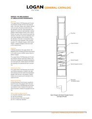
OVERVIEW<br />
The hydraulic motor-driven, <strong>Logan</strong><br />
<strong>85</strong>-<strong>Ton</strong> <strong>Power</strong> <strong>Swivel</strong> provides smooth,<br />
shock-free torque. It is rated to support<br />
tensile pipe loads of <strong>85</strong> tons at zero<br />
rpm and 45 tons of dynamic load at 100<br />
rpm. The compact, swivel-head design<br />
weighs only 1,163 lbs and fits into most<br />
drilling or workover masts.<br />
The design incorporates a reliable,<br />
custom drive train with hardened steel<br />
gears. For most applications, the <strong>Logan</strong><br />
<strong>85</strong>-<strong>Ton</strong> <strong>Power</strong> <strong>Swivel</strong> eliminates the use<br />
of dangerous spinning chains, tongs,<br />
and kelly spinners. The <strong>Power</strong> <strong>Swivel</strong><br />
facilitates drilling with longer drill string<br />
lengths before the rig must be shut<br />
down to add pipe. Stops and start-ups<br />
are thereby reduced — improving rig<br />
efficiency and reducing wear on the<br />
pump, drawworks, and other rig equipment.<br />
The <strong>Logan</strong> <strong>85</strong>-<strong>Ton</strong> <strong>Power</strong> swivel uses<br />
a closed loop hydraulic system with a<br />
variable displacement, bi-directional<br />
pump, and air or electric remote controls.<br />
Speed control is continuously<br />
variable over the entire operating range.<br />
Pressure compensating-type torque<br />
control overrides the speed control to<br />
maintain maximum torque. The power<br />
unit’s torque limits can be set, thereby<br />
eliminating the potential danger of twistoffs<br />
or swollen boxes in the drill string.<br />
An integral rotary swivel bearing, floating<br />
washpipe assembly, and gooseneck<br />
connection eliminates the need for a<br />
separate rotary swivel.<br />
A 2-1/2" bore gooseneck and washpipe<br />
assembly allows circulation through the<br />
2" I.D. stem while rotating or in static<br />
mode. An access plug allows wireline<br />
to be run through the unit.<br />
Features include:<br />
• Smooth, shock-free torque reduces<br />
drill string damage<br />
• Fits most drilling and work over masts<br />
• Allows use of longer drill string lengths<br />
• <strong>Power</strong> unit torque limits can be set<br />
• Separate rotary swivel is unnecessary<br />
• Choice of diesel engines<br />
• Increased environmental safety<br />
features on skids and trailers<br />
• Easy to service<br />
Extra cost options, just to name a few,<br />
include:<br />
• Air- or hydro-start engine<br />
• Special hydraulic motor<br />
• Lifting frame<br />
• Electric or hydraulic loading winch<br />
• Hydraulic motor brakes<br />
• Control can be operated remotely<br />
or from the power unit<br />
• Cold weather package<br />
The complete <strong>Logan</strong> <strong>85</strong>-<strong>Ton</strong> <strong>Power</strong><br />
<strong>Swivel</strong> package includes an elevatortype<br />
bail or hook-link adapters; a<br />
unitized washpipe packing box assembly;<br />
a fixed displacement, piston-type,<br />
hydraulic motor rated at 5,000 psi;<br />
a torque rein assembly; safety cable;<br />
and 1-inch quick disconnects. The components<br />
are available either trailer- or<br />
skid-mounted with powered hose reels<br />
to form a rugged unit. A swivel carrying<br />
stand is standard.<br />
CAUTION: Refer to the installation<br />
procedure outlined on page 4 before<br />
installing the <strong>Logan</strong> <strong>85</strong>-<strong>Ton</strong> <strong>Power</strong><br />
<strong>Swivel</strong> on a rig. Failure to install the<br />
<strong>Power</strong> <strong>Swivel</strong> properly can result in<br />
injury to the operator and/or rig floor<br />
personnel. Read Important Safety<br />
Information below.<br />
USES<br />
The <strong>Logan</strong> <strong>85</strong>-<strong>Ton</strong> <strong>Power</strong> <strong>Swivel</strong> is ideally<br />
suited for use in fishing and workover<br />
operations — such as the internal<br />
or external cutting of casing, tubing, or<br />
drill pipe; drilling out plugs, packers, or<br />
cement; milling operations; or scraping<br />
casing — whenever shock-free, controlled<br />
torque is essential to eliminating<br />
the potential danger of twist-offs or<br />
damage to cutting tools.<br />
The compact, lightweight swivel-head<br />
design also makes it extremely effective<br />
for light to medium drilling applications<br />
including water wells, pilings for piers<br />
and foundations, in addition to oil and<br />
gas wells. Suspending the swivel from<br />
a boom or crane eliminates a great deal<br />
of set-up time or shifts to additional<br />
locations.<br />
The <strong>Logan</strong> <strong>85</strong>-<strong>Ton</strong> <strong>Power</strong> <strong>Swivel</strong> is also<br />
ideal for coring operations. Any length<br />
of core may be taken. Accurate and<br />
smooth torque ensures against damage<br />
to core tools or strings.<br />
IMPORTANT<br />
SAFETY INFORMATION<br />
Before operating the <strong>Logan</strong> <strong>85</strong>-<strong>Ton</strong><br />
<strong>Power</strong> <strong>Swivel</strong>, users are advised of the<br />
following important safety precautions<br />
and procedures:<br />
1. Verify the strength of the derrick<br />
structure and torque rein guide cable<br />
to ensure they are strong enough to<br />
withstand the loads imposed by the<br />
<strong>Power</strong> <strong>Swivel</strong>.<br />
<strong>Logan</strong> <strong>85</strong>-<strong>Ton</strong> <strong>Power</strong> <strong>Swivel</strong> • 2
2. A <strong>Logan</strong> Safety Cable (provided as<br />
standard equipment on the <strong>Logan</strong> <strong>85</strong>-<br />
<strong>Ton</strong> <strong>Power</strong> <strong>Swivel</strong>) should be used for<br />
torque rein and should be utilized at<br />
all times. Attach one end of the safety<br />
cable to the torque rein and secure<br />
the other end to the swivel. In the<br />
event of torque rein assembly failure,<br />
the safety cable will prevent the<br />
assembly from falling to the rig floor.<br />
3. Carefully check the full range of<br />
travel in the derrick or mast before<br />
beginning operations. With the guide<br />
cable as nearly vertical as possible,<br />
ensure that the swivel can move<br />
freely up and down under full torque<br />
in either direction. Angles exceeding<br />
5% can cause side loads on the<br />
swivel.<br />
4. Tubing elevators should not be<br />
used with <strong>Power</strong> <strong>Swivel</strong> bails.<br />
Besides being a potentially danger-<br />
ous practice, the use of an upset<br />
elevator reduces the contact between<br />
the elevator and bail, and accelerates<br />
wear.<br />
5. Inspect elevators and bails for exces-<br />
sive wear according to guidelines<br />
published in API RP-8B.<br />
WARNING: Failure to comply with<br />
these safety procedures may cause<br />
physical injury to the operator and/or<br />
rig floor personnel.<br />
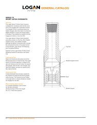
CONSTRUCTION<br />
<strong>Power</strong> <strong>Swivel</strong> Assembly<br />
The <strong>Logan</strong> <strong>85</strong>-<strong>Ton</strong> <strong>Power</strong> <strong>Swivel</strong> is<br />
powered by a fixed displacement,<br />
piston-type, hydraulic motor rated at<br />
5,000 psi. The motor is mounted on the<br />
underside of the swivel and is protected<br />
by a steel frame.<br />
3 • <strong>Logan</strong> <strong>85</strong>-<strong>Ton</strong> <strong>Power</strong> <strong>Swivel</strong><br />
Lightweight, compact swivel-head design<br />
fits most drilling or workover masts.<br />
Two high pressure hydraulic hoses and<br />
the motor drain hose exit from the bottom<br />
of the assembly. The high pressure<br />
hydraulic hoses connect to the motor<br />
with quick disconnetcs. The motor drain<br />
hose is fitted with a self-sealing quick<br />
dis-connect coupling.<br />
The one-piece gooseneck is constructed<br />
of cast steel. A 2-inch I.D. NPT access<br />
plug located in the top allows passage<br />
of wireline and small tools through<br />
the swivel for downhole operations.<br />
The gooseneck and swivel packing are<br />
hydrostatically tested and rated at 5,000<br />
psi circulating pressure.<br />
The floating washpipe assembly and<br />
packing are self-aligning. Friction bearing<br />
surfaces of the washpipe (areas that<br />
contact the packing) are hard-surfaced<br />
for wear-resistance.<br />
The elevator bail is machined from<br />
forged, heat-treated alloy steel for<br />
maximum strength. The bail, bail pins,<br />
and body are manufactured to API<br />
guidelines.<br />
The design incorporates a reliable,<br />
custom drive train with hardened steel<br />
gears consisting of: a motor drive gear,<br />
reduction drive gear, an intermediate<br />
gear, and the main drive gear. Roller<br />
bearings keep the gears in close alignment.<br />
A magnetic drain plug is located on the<br />
lower cover plate of the swivel assembly.<br />
A tell-tale hole in the lower plate<br />
indicates hydraulic oil leakage past the<br />
motor shaft seal or lubricating gear oil<br />
past the input pinion shaft. A filler/relief<br />
plug is located on the upper cover plate.<br />
The gear housing is equipped with an<br />
oil level sight glass so the operator may<br />
check oil level with a quick glance.<br />
To protect the main stem oil seal from<br />
dirt, an excluder seal is installed below<br />
the packing nut.<br />
Control Units<br />
Air controls consist of an air compressor<br />
and tank, an air filter/regulator/lubricator<br />
unit, and a pedestal mounted control<br />
panel with extra lines fitted with quick<br />
disconnect couplers. A lever-operated<br />
air valve controls the engine speed.<br />
Another single-lever air valve controls<br />
the direction and speed of the <strong>Power</strong><br />
<strong>Swivel</strong>. A torque gauge, calibrated in<br />
ft-lbs, indicates torque.<br />
Control assemblies for the <strong>Logan</strong><br />
<strong>85</strong>-<strong>Ton</strong> <strong>Power</strong> <strong>Swivel</strong> are either air or<br />
electric. They can be operated remotely<br />
(extra cost option) for operator convenience<br />
and safety, or from the power<br />
unit. Remote control assemblies are<br />
pedestal mounted. The control assembly<br />
is lightweight and the pedestal base<br />
is removable for easy storage on the<br />
trailer or skid. A new wireless remote<br />
with an operating range of 150 feet is<br />
also available.
The electric control panel consists of a<br />
rotary switch for controlling swivel direction<br />
and speed, an engine rpm control<br />
switch, a digital torque gauge, and an<br />
engine kill switch. An emergency kill<br />
switch is available for hazardous locations.<br />
Torque limits can be easily and accurately<br />
set on both air and electric control<br />
units. A torque control unit mounted<br />
on the fuel tank can be preset to the<br />
desired torque limit with the turn of<br />
a knob. Torque will be indicated on the<br />
control panel in ft-lbs.<br />
Basic <strong>Power</strong> System<br />
The <strong>Logan</strong> <strong>85</strong>-<strong>Ton</strong> <strong>Power</strong> <strong>Swivel</strong> is<br />
equipped with a diesel engine to provide<br />
power. The engine is sized to<br />
provide sufficient horsepower to operate<br />
the swivel to full torque and rpm limits.<br />
Control systems may be either air or<br />
electric.<br />
On units equipped with air control systems,<br />
an air compressor, a three-gallon<br />
receiver tank, and an air filter-lubricator<br />
are also provided.<br />
Hydraulic System<br />
The hydraulic system includes a direct<br />
driven, variable displacement hydraulic<br />
pump that is mounted directly on the<br />
engine flywheel housing. All piping,<br />
valves, fittings, reservoirs, and other<br />
components required to complete the<br />
system are included. The hydraulic<br />
system is designed and rated at 5,000<br />
psi working pressure.<br />
The hydraulic reservoir is designed to<br />
dissipate heat and is adequately sized<br />
to disperse foam that may be generated<br />
during operation. A suction strainer and<br />
high pressure filters provide continuous<br />
filtration of the hydraulic fluid. Visual<br />
registers on the tank return filter and<br />
high pressure filters indicate when<br />
these elements need to be replaced.<br />
Hydraulic hoses are reel-mounted<br />
on the power unit. They are connected<br />
to the power swivel hydraulic motor with<br />
quick disconnects.<br />
A swivel carrying rack allows the swivel<br />
to be loaded and unloaded without<br />
breaking the hose connections.<br />
<strong>Power</strong> Unit<br />
The compact, easily transportable<br />
<strong>Power</strong> <strong>Swivel</strong> units may be mounted on<br />
a trailer, skid, or containerized. All units<br />
consist of an engine with a hydraulic<br />
pump, hydraulic piping, a hydraulic fluid<br />
reservoir, a hose reel assembly and<br />
hoses necessary for supplying hydraulic<br />
Gooseneck Trailer-Mounted Unit, Side View<br />
power to the power swivel motor. Brackets<br />
to hold and transport the swivel and<br />
the control panel are included.<br />
Trailer-Mounted Unit<br />
The compact, tandem axle units meet<br />
all ICC regulations and are equipped<br />
with heavy-duty springs and electric<br />
brakes. The trailer can be supplied as<br />
a gooseneck or a bumper pull trailer.<br />
Diamond-patterned deck plate provides<br />
solid, skid resistant flooring over the all<br />
welded, steel frame.<br />
Skid-Mounted Unit<br />
Skid units are rugged and made of<br />
heavy-duty structural tubing with welded<br />
construction. Both ends are rounded<br />
for easy skidding. Ends are fitted with<br />
an integral pipe that may be used to<br />
attach boom lines or hoist slings. Main<br />
runners, running the length of the skid,<br />
are strengthened by cross-members for<br />
additional rigidity. The entire frame is<br />
covered with diamond-patterned deck<br />
plate to provide a solid, skid resistant<br />
floor.<br />
To meet environmental regulations,<br />
both trailer- and skid-mounted units are<br />
equipped with an integral containment<br />
lip to contain fluid spills.<br />
<strong>Logan</strong> <strong>85</strong>-<strong>Ton</strong> <strong>Power</strong> <strong>Swivel</strong> • 4
Containerized Unit<br />
Containerized units are built into a 20foot<br />
ocean container. The containers<br />
are equipped with two bi-fold doors on<br />
one side, and double doors in the rear,<br />
to allow complete access. A louvered<br />
vent, which has an adjustable cover that<br />
can be sealed off for storage or transport,<br />
is installed on the front. The floor<br />
is diamond tread steel plate.<br />
INSTALLATION<br />
Rig Up<br />
Check all components to ensure that<br />
all accessory items (especially the portable<br />
control panel) and spare parts<br />
are packed, and that all equipment is<br />
in serviceable condition. If time permits,<br />
the operator should run the power<br />
swivel for a short time to check control<br />
indicators, filter, and response of controls,<br />
etc. before leaving for the job site.<br />
Be sure to have an ample supply of fuel<br />
and that the hydraulic reservoir is full.<br />
Upon arriving at the job site, the power<br />
unit should be placed in a level position<br />
a safe distance from the well head and<br />
other hazards. All corners of skid units<br />
should be supported. On trailer units,<br />
wheel chocks should be set in front and<br />
in back of the wheels and the jack lowered<br />
to level the trailer bed.<br />
Using a catline or derrick line, lift the<br />
swivel unit from the rack. Suspend<br />
the swivel over the well head from the<br />
drilling hook or elevators. Be sure the<br />
elevator is the correct size for the elevator<br />
bail. Carefully inspect the elevator<br />
for excessive wear (refer to API RP-8B<br />
for guidelines).<br />
Remove the control cable or air control<br />
hoses and the pressure gauge hose<br />
from their storage hangers on the skid<br />
or trailer. Connect them to their respective<br />
connections on the power unit and<br />
control panel.<br />
5 • <strong>Logan</strong> <strong>85</strong>-<strong>Ton</strong> <strong>Power</strong> <strong>Swivel</strong><br />
Pre-Operation Start-up Procedures<br />
Electric Controls<br />
1. Move the "ENGINE" throttle switch<br />
to “IDLE” position.<br />
2. Move the swivel "SPEED" knob to<br />
the "STOP" position (left).<br />
3. Turn on the control power at the<br />
<strong>Power</strong> Unit.<br />
4. Start the engine and allow the unit<br />
to warm up.<br />
5. Turn the "ENGINE" switch to the<br />
"RUN" position.<br />
6. Set the torque limit using the control<br />
panel located on top of the fuel tank,<br />
stroke the pump "FWD" and adjust<br />
the torque set knob to the desired<br />
maximum torque.<br />
7. Set the "DIRECTION" switch to the<br />
desired rotation — "FWD" or "RVS"<br />
(the center position is neutral).<br />
8. Slowly increase the "SPEED" knob<br />
until the swivel reaches the desired<br />
speed or the maximum torque limit.<br />
<strong>Power</strong> <strong>Swivel</strong> Electric Control Panel<br />
9. Check the high pressure filters<br />
located on the fuel tank. If the indi-<br />
cator is in the red, change the filters.<br />
10. Check the return filter. If the indica-<br />
tor gauge is in the red, replace the<br />
filter.<br />
Air Controls<br />
1. Move the engine throttle control<br />
lever to idle position (decrease).<br />
2. Move the swivel control lever to<br />
neutral position (center).<br />
3. Start the engine and allow the unit<br />
to warm up.<br />
4. Check the condition of the return<br />
filter. The filter indicator is located<br />
on top of the hydraulic reservoir.<br />
Replace the filter if the gauge is in<br />
the red.<br />
5. Check the air filter/regulator/<br />
lubricator unit. Air pressure should<br />
read 100 psi or more. Lubricator<br />
should be full of oil. Filter should be<br />
free of water. If water is present,
open the drain valve on the bottom<br />
of air reservoir to drain the water.<br />
Close the drain valve.<br />
6. Set the torque control to the desired<br />
maximum torque. The torque con-<br />
trol system is mounted on top of the<br />
fuel tank. The adjustment knob and<br />
torque indicator gauge are cali-<br />
brated in ft-lbs. Turn the adjustment<br />
knob until the desired maximum<br />
torque is indicated on the gauge.<br />
7. Move the swivel control handle to<br />
the “forward” position.<br />
8. Increase engine throttle until the<br />
desired engine rpm is attained and<br />
the engine runs smoothly.<br />
9. Check the high pressure filter<br />
indicator.<br />
The <strong>Logan</strong> <strong>85</strong>-<strong>Ton</strong> <strong>Power</strong> <strong>Swivel</strong> is now<br />
ready for operation.<br />
OPERATION<br />
General Rules<br />
<strong>Logan</strong> <strong>Oil</strong> <strong>Tools</strong> recommends the following<br />
rules be observed when operating<br />
the <strong>Power</strong> <strong>Swivel</strong>. These operational<br />
rules apply to all power swivel units,<br />
whether they are equipped with air or<br />
electric controls.<br />
<strong>Power</strong> <strong>Swivel</strong> Air Control Panel<br />
1. The pump displacement control<br />
should always be used to change<br />
the speed of the swivel. Setting the<br />
engine at the rated rpm will prolong<br />
engine and pump life, burn less oil,<br />
and result in increased fuel economy.<br />
2. When changing the direction of<br />
rotation, move the <strong>Swivel</strong> Control to<br />
the center or neutral position, wait<br />
for the swivel to come to a complete<br />
stop, and then proceed with the<br />
change in rotation.<br />
3. Filters should be checked on a daily<br />
basis.<br />
4. The hydraulic fluid level should be<br />
checked daily. If the level is below<br />
the sight gauge, add hydraulic fluid.<br />
5. Do not permit the hydraulic oil<br />
temperature to exceed 190°F for<br />
extended periods.<br />
Air Controls<br />
The air control system utilizes a levertype<br />
control valves that are mounted<br />
on the remote control panel. These controls<br />
provide variable air pressure from<br />
0 to 100 psi to the actuator/positioner<br />
to control both engine rpm and the<br />
speed/direction of swivel rotation.<br />
When the swivel control lever is in the<br />
center position, the pump is in neutral<br />
and the <strong>Power</strong> <strong>Swivel</strong> is not rotating.<br />
Electric Controls<br />
Diesel engine rpm is controlled by<br />
the switch labeled “ENGINE” on the<br />
control panel.<br />
<strong>Swivel</strong> rotation is controlled by the knob<br />
labeled “SWIVEL RPM.” It utilizes a<br />
forward/neutral/reverse switch to control<br />
rotation direction. Moving the switch to<br />
the “FORWARD” position will cause the<br />
<strong>Power</strong> <strong>Swivel</strong> to move in a right-hand<br />
(clockwise) direction.<br />
Turn the “ENGINE” switch to "RUN" to<br />
increase engine rpm.<br />
Pressure compensating-type torque<br />
control overrides the speed control to<br />
automatically maintain the maximum<br />
pre-established torque limit. This is<br />
accomplished by destroking the pump<br />
while maintaining engine speed.<br />
MAINTENANCE<br />
The following guidelines are intended<br />
to ensure maximum life of the <strong>Logan</strong><br />
<strong>85</strong>-<strong>Ton</strong> <strong>Power</strong> <strong>Swivel</strong>. These are recommendations<br />
only. Extreme peak load<br />
usage, temperature, and other variables<br />
will affect suggested service intervals.<br />
<strong>Logan</strong> <strong>85</strong>-<strong>Ton</strong> <strong>Power</strong> <strong>Swivel</strong> • 6
<strong>Power</strong> <strong>Swivel</strong> Maintenance<br />
Lubrication<br />
1. Check the gear lubricating oil prior<br />
to service. The oil level should be<br />
maintained at the oil level plug level<br />
at all times. If necessary, bring oil to<br />
the proper operating level by adding<br />
<strong>85</strong>w 140 gear lubricant. Some lubri-<br />
cating oil may leak out when the oil<br />
level plug near the top cover plate is<br />
removed. If oil does not leak out, gear<br />
lubricating oil of proper type and<br />
grade should be added to the correct<br />
operating level.<br />
2. Gear lubricating oil should be<br />
changed after the first 100 hours of<br />
initial operation. Check the magnetic<br />
drain plug for metal filings when<br />
changing the gear lubricating oil.<br />
NOTE: <strong>Oil</strong> capacity of the <strong>Logan</strong> <strong>85</strong>-<br />
<strong>Ton</strong> <strong>Power</strong> <strong>Swivel</strong> is two (2) gallons.<br />
3. After the initial break-in period (first<br />
100 hours of operation), the gear<br />
lubricating oil should be changed<br />
after each 1,000 hours of operation<br />
thereafter, or if the unit has been out<br />
of service for an extended period.<br />
Always check the magnetic drain<br />
plug for metal filings when changing<br />
the gear lubricating oil.<br />
4. The elevator bail, stem, and saver<br />
subs should undergo magnetic par-<br />
ticle inspection every five (5) years.<br />
Breaking-In<br />
During initial break-in, or after a long<br />
period of idleness, run the <strong>Power</strong> <strong>Swivel</strong><br />
with a reduced load at slower speed<br />
until it reaches normal operating temperature<br />
ranging between 120 – 200°F.<br />
A somewhat higher operating temperature<br />
is permissible in very hot climates,<br />
provided that it increases gradually.<br />
Storage<br />
If the <strong>Logan</strong> <strong>85</strong>-<strong>Ton</strong> <strong>Power</strong> <strong>Swivel</strong> must<br />
be stored, it should be completely filled<br />
with gear lubricating oil to prevent oxidation.<br />
Thread protectors or lift plugs<br />
should be installed on stems or saver<br />
7 • <strong>Logan</strong> <strong>85</strong>-<strong>Ton</strong> <strong>Power</strong> <strong>Swivel</strong><br />
subs to prevent damage to the threads.<br />
Grease or dope the threads before<br />
installing the thread protectors or lift<br />
plugs.<br />
Open gear housings, ports, and removed<br />
motors should be covered with<br />
clean drop cloths to prevent dirt and<br />
trash from entering internal mechanisms.<br />
Before shipping parts for service,<br />
all openings should be sealed and parts<br />
wrapped in clean, heavy kraft paper.<br />
Replacing the Floating Washpipe<br />
Assembly and Packing<br />
The entire Floating Washpipe Assembly,<br />
including the upper and lower packing<br />
nuts, can be removed from the swivel<br />
without removing the gooseneck or<br />
bonnet.<br />
Remove the four retainers and retaining<br />
screws from the lower packing nut.<br />
Loosen the lower packing nut by turning<br />
it in a clockwise direction until it turns<br />
freely. Secure the upper stem to keep<br />
it from rotating while loosening and<br />
removing the lower packing nut. Use<br />
the same procedure to loosen and<br />
remove the upper packing nut from the<br />
gooseneck.<br />
Remove the washpipe and packing assemblies.<br />
Press the washpipe out<br />
of the lower packing nut and slide the<br />
upper nut off. Remove the three upper<br />
packing locking pins and press the upper<br />
packing off the washpipe. Replace<br />
the washpipe if it shows any signs of<br />
wear (i.e., scoring or surface abrasion).<br />
The average life expectancy of the<br />
packing is 200 – 250 hours. Remove<br />
the old packing from the packing nuts.<br />
Thoroughly clean the inside of both<br />
nuts. Using the drawing on page 8 as<br />
a reference, install the new packing.<br />
Assemble the packing and floating<br />
washpipe assembly in reverse of assembly<br />
procedure. Tighten the packing<br />
nuts securely, locking them in place with<br />
the retaining screws and retainers.<br />
<strong>Power</strong> Unit Maintenance<br />
The <strong>Power</strong> Unit includes the engine,<br />
piping, filters, reservoir, hoses, hose<br />
reels, cables, electrical components,<br />
and gauges.<br />
Engine<br />
Please refer to the specific engine manufacturer’s<br />
maintenance instructions<br />
included with your documentation.<br />
Hydraulic <strong>Oil</strong> and Filters<br />
The hydraulic fluid reservoir (<strong>Logan</strong> Part<br />
No. PS06206) should be maintained<br />
at the proper level at all times. The<br />
oil level should be visible in the sight<br />
gauge when cold.<br />
Filters<br />
The return filter located at the top of the<br />
reservoir should be replaced when the<br />
pointer indicates that it needs cleaning.<br />
The indicator registers when the engine<br />
is running.<br />
The high pressure filter in the pressure<br />
line should be serviced when the<br />
condition indicator displays red. Green<br />
indicates that the filter is in satisfactory<br />
condition. The filter indicator operates<br />
when the swivel is rotating to the right.<br />
Hoses<br />
Lubricate the hose reel swivel joints<br />
with automotive chassis grease<br />
monthly.<br />
Inspect the torque control mechanism<br />
every six months and coat all moving<br />
parts with automotive chassis grease.<br />
Avoid contaminating the hydraulic fluid<br />
and hydraulic system, including the<br />
hoses and couplings, with dust, water,<br />
or other foreign matter. Introduction of<br />
foreign materials into the system will<br />
damage the machinery.<br />
Torque gauge hose end connections<br />
should be kept clean at all times<br />
through the use of dust covers or by<br />
wrapping them with a clean cloth when<br />
not in use. Open, loose ends, especially<br />
those that have been dropped on the<br />
ground, should be thoroughly cleaned<br />
inside and out, and flushed prior to use.
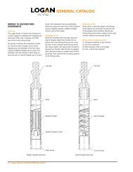
Body<br />
PS54075<br />
3<br />
1<br />
2<br />
4<br />
5<br />
6<br />
7<br />
8<br />
9<br />
10<br />
11<br />
12<br />
13 14<br />
ITEM LOGAn PART nO. QTy DESCRIPTIOn<br />
2" NPT<br />
1 PS09028 1 Gooseneck<br />
2 ACSA8-500-13-150 4 1/2" - 13 x 1-1/2" Socket Head Cap Screw<br />
3 LKWA-500 4 1/2" Lock Washer<br />
4 PS19028 1 Bonnet<br />
5 568236-100 2 O-Ring<br />
6 PS79028 1 Upper Packing Nut Ring<br />
7 PS50732-003 8 1/2" - 13 NC x 3/4 Socket Set Screw<br />
8 PS20128 8 Washpipe Packing Nut Screw Retainer<br />
9 PS99028-001 3 Washpipe Locking Pin with O-Ring<br />
10 568010-100 3 O-Ring<br />
Gooseneck Pipe Plug<br />
PS77322<br />
FLOATING WAShPIPE ASSEMbLY (PS49028-001) REPLACEMENT PARTS<br />
15<br />
ITEM LOGAn PART nO. QTy DESCRIPTIOn<br />
16<br />
17<br />
18<br />
11<br />
19<br />
8<br />
7<br />
20<br />
5<br />
2-1/2 API<br />
LINE PIPE<br />
11 PS72327 1 Packing Set<br />
12 PS39028 1 Upper Packing Nut<br />
13 ACSA8-625-13-150 4 5/8" - 11 x 1-1/2" Socket Head Cap Screw<br />
14 LKWA-625 4 5/8" Lock Washer<br />
15 PS49028 1 Washpipe<br />
16 PS69028 1 Spacer and Lantern Ring<br />
17 PS63672 1 Packing Nut Grease Fitting<br />
18 PS62327 1 Plain Spacer Ring<br />
19 PS42327 1 Packing Bottom Ring<br />
20 PS29028 1 Lower Packing Nut<br />
<strong>Logan</strong> <strong>85</strong>-<strong>Ton</strong> <strong>Power</strong> <strong>Swivel</strong> • 8
Extend the life of the hoses by never<br />
allowing them to become twisted or<br />
kinked, or unnecessarily stretched. Do<br />
not allow any sharp or heavy objects<br />
to drop or lay on the hoses. Doing so<br />
may cut or crush them.<br />
Machinery and hoses should not be<br />
allowed to remain outdoors when not<br />
in use.<br />
In cold climates, it is particularly important<br />
to keep the hydraulic system free<br />
of moisture caused by condensation or<br />
water contaminated hydraulic fluid. Any<br />
moisture in the system may freeze and<br />
cause severe damage, especially to the<br />
pump and valves.<br />
<strong>Power</strong> Unit<br />
Inspect trailer-mounted units prior to<br />
use to ensure that it is safe and roadworthy.<br />
Pay particular attention when<br />
inspecting the following items:<br />
1. Trailer hitch and safety chain<br />
2. Brakes and tires<br />
3. Tail and brake lights, and turn signals<br />
4. Reserve fuel supply<br />
5. Trailer tongue jack and supports<br />
Thoroughly clean the power unit when<br />
the job has been completed. Replenish<br />
the engine fuel and hydraulic oil supplies.<br />
Make any necessary repairs at<br />
this time. Hoses should be reeled after<br />
cleaning and the hose ends covered.<br />
<strong>Power</strong> Units with Air Controls<br />
Expel water condensate from the tank<br />
daily by opening the drain valve on the<br />
bottom of the air receiver. Pressurize<br />
the tank before opening the valve.<br />
Visually inspect the filter/lubricator valve<br />
twice a day. Drain any water that has<br />
collected in the filter bowl and maintain<br />
the lubricating oil at the proper operating<br />
level with SAE 10W motor oil.<br />
Always keep the pump stroke cylinder<br />
rod, rod bearing, and clevis coated with<br />
chassis grease.<br />
9 • <strong>Logan</strong> <strong>85</strong>-<strong>Ton</strong> <strong>Power</strong> <strong>Swivel</strong><br />
<strong>Power</strong> Units with Electric Controls<br />
The electrical cable should be coiled<br />
and stored on the cable bracket when<br />
not in use. Cover the open end with<br />
the provided dust cap. Avoid kinking<br />
or placing undue tension on the cable.<br />
Do not allow equipment to run over the<br />
cable.<br />
Open the relay cabinet at least once<br />
a year (more often in humid climates)<br />
for cleaning. All exposed terminals and<br />
metal parts should be cleaned, dried,<br />
and sprayed with silicone or varnish.<br />
<strong>Power</strong> <strong>Swivel</strong><br />
<strong>Power</strong> swivels should not be started<br />
or operated in freezing weather until<br />
the hydraulic system has been properly<br />
prepared for cold weather service by:<br />
1. Charge the hydraulic system with<br />
hydraulic oil rated for cold weather.<br />
2. Prepare the engine according to the<br />
manufacturer's recommendations.<br />
3. Ensure the hydraulic system is<br />
moisture-free.<br />
SWIVEL DISASSEMbLY<br />
Gooseneck Trailer-Mounted Unit, Rear View<br />
Care should be taken to ensure that<br />
no foreign material enters the interior<br />
machinery of the swivel. All disassembly<br />
and major repairs should be conducted<br />
in a clean, well-equipped shop.<br />
1. Remove all hydraulic hoses from the<br />
swivel. Hose ends should be covered<br />
to help prevent foreign matter from<br />
entering the interior.<br />
NOTE: When not in use, all hydraulic<br />
hoses should be reeled up to<br />
prevent kinking and other damage.<br />
Damaged hoses may cause blockage<br />
or other interference that the unit<br />
may not function properly.<br />
2. Place the swivel on a suitable rack<br />
(similar to the bracket on the skid or<br />
trailer) that supports the swivel on its<br />
bail pins.<br />
3. Remove the hydraulic motor guard.<br />
4. Place an open container under the<br />
magnetic drain plug and remove<br />
the plug. Check the drain plug and<br />
drained gear oil for metal filings and<br />
other foreign matter.
5. Remove the four retaining screws<br />
and their retainers from the lower<br />
packing nut. Secure the lower stem<br />
of the swivel to keep the upper stem<br />
from turning while loosening the lower<br />
packing nut. Turn the lower packing<br />
nut in a clockwise direction until it<br />
turns freely. Back the lower packing<br />
nut completely off the upper stem.<br />
Repeat the above procedure to<br />
remove the upper packing nut and<br />
back it completely off the gooseneck.<br />
Remove the floating washpipe and<br />
packing assembly.<br />
6. Press the washpipe out of the lower<br />
packing nut and slide the upper nut<br />
off. Remove the three upper packing<br />
locking pins and press the upper<br />
packing off the washpipe. Replace<br />
the washpipe if it shows any signs of<br />
wear (scoring or surface abrasion).<br />
7. Remove the packing assembly parts<br />
from inside both nuts. (The lower<br />
packing assembly consists of an<br />
O-ring, packing bottom ring, plain<br />
spacer ring, spacer and lantern ring,<br />
and three packing seals. The upper<br />
packing assembly consists of an<br />
O-ring, upper packing nut ring, and<br />
one packing seal.) When replacing<br />
the packing, it is important that both<br />
packing nuts are clean and free of all<br />
old packing residue. Make sure both<br />
packing nuts are clean and free of<br />
foreign matter.<br />
8. Remove and set aside the goose<br />
neck and bonnet.<br />
9. Turn the swivel upside down. Remove<br />
the hydraulic motor and set it<br />
aside.<br />
NOTE: Do not disassemble the hydraulic<br />
motor. If trouble with the motor<br />
is known or suspected, carefully<br />
plug the ports and return the motor<br />
to <strong>Logan</strong> <strong>Oil</strong> <strong>Tools</strong> for inspection and<br />
repair.<br />
10. Remove the lower bearing retainer<br />
screws. Set the retainer aside and<br />
remove the gasket.<br />
11. Remove the seal retainer snap ring<br />
from the bearing retainer and the<br />
two lower oil seals.<br />
12. Turn the swivel upright and remove<br />
the upper seal protector from the top<br />
of the stem.<br />
13. Remove the cap screws from the<br />
top cover plate. A rubber mallet may<br />
be used to break the gasket seal<br />
if necessary. Lift off the top cover<br />
plate.<br />
14. Remove the upper gear cover shim<br />
and gasket. A putty knife or other<br />
thin tool may be used for prying and<br />
cleaning.<br />
15. Remove the oil seal from the upper<br />
cover plate. Using an inside bearing<br />
puller, pull the outer race of the<br />
stem upper bearing from the top<br />
cover plate. This will free the stem<br />
for removal.<br />
16. The inner race of the stem’s upper<br />
and lower bearings and seal wear<br />
ring at the bottom of the stem may<br />
be removed with a bearing puller.<br />
The final reduction gear is removed<br />
by first removing the six ring groove<br />
pins and then forcing the gear off the<br />
main stem.<br />
17. Remove the screws from the lower<br />
gear cover plate. Tap the cover plate<br />
gently with a rubber mallet to break<br />
the seal if necessary. Scrape off<br />
remaining residue with a putty knife.<br />
18. Remove the first reduction pinion<br />
bearing spacer and the first reduc-<br />
tion pinion lower bearing from the<br />
swivel body.<br />
19. Lift out the final reduction pinion,<br />
main thrust bearing, second reduc-<br />
tion pinion, and first reduction<br />
pinion. The gears may require<br />
rotation to facilitate removal.<br />
20. Remove the remaining roller bear-<br />
ings, second reduction lower bear-<br />
ing with its retainer ring, and first<br />
reduction pinion upper bearing. As<br />
with all bearings, exercise caution<br />
when handling to guard against<br />
possible damage.<br />
NOTE: Each part should be thoroughly<br />
cleaned (with steam or a high<br />
pressure washer for metal parts, or<br />
with a good grade solvent) as it is<br />
removed. Check parts for repair or<br />
replacement as they are cleaned. Dry<br />
all cleaned parts with compressed air<br />
or a clean, soft cloth. Coat all clean,<br />
dry parts with a thin coat of lubricating<br />
oil. Never leave parts exposed<br />
overnight without a coating of protective<br />
oil.<br />
21. Remove the bail only when abso-<br />
lutely necessary. Lay the bail and<br />
swivel body down so the holes at<br />
the bottom of the bail pockets in the<br />
body can be reached. Set a 10-<br />
inch-long dowel rod with a diameter<br />
slightly smaller than the bail pocket<br />
holes against the pin. Strike the<br />
dowel with a hammer. Once the<br />
grooved pin has been removed,<br />
insert a rod in the pull pin hole. Use<br />
a rubber mallet to loosen the bail<br />
pin by tapping it in alternate direc-<br />
tions. Pour penetrating oil around<br />
the pin to aid the loosening process.<br />
While pulling on the pin, repeat the<br />
loosening process until the pin is<br />
removed. Lift out the bail.<br />
NOTE: In the event hydraulic motors,<br />
hoses, or similar items are to be<br />
stored or shipped for repair, all ports<br />
and openings should be carefully<br />
sealed to prevent foreign matter from<br />
entering interior parts.<br />
<strong>Logan</strong> <strong>85</strong>-<strong>Ton</strong> <strong>Power</strong> <strong>Swivel</strong> • 10
<strong>Swivel</strong> head Parts List<br />
Item numbers refer to drawing callouts on pages 12 – 15<br />
ITEM PART nO. QTy. DESCRIPTIOn<br />
1 PS09028 1 Gooseneck<br />
2 ACSA8-500-13-150 14 1/2" - 13 x 1-1/2" Long Socket Head Cap Screw<br />
3 LKWA-500 18 1/2" Lockwasher<br />
4 PS19028 1 Bonnet<br />
5 568236 2 O-Ring<br />
6 PS79028 1 Upper Packing Nut Ring<br />
7 PS50732-003 8 1/2" - 13 NC x 3/4" Long Socket Set Screw<br />
with Brass Point<br />
8 PS20128 8 Washpipe Packing Nut Screw Retainer<br />
9 PS99028 3 Washpipe Locking Pin with 568010 O-Ring<br />
10 568010 3 O-Ring<br />
11 PS72327 1 Set Packing<br />
12 PS39028 1 Upper Packing Nut<br />
13 ACSA8-625-13-150 8 5/8" - 11 x 1-1/2" Long Socket Head Cap Screw<br />
14 LKWA-625 23 5/8" Lockwasher<br />
15 PS49028 1 Washpipe<br />
16 PS69028 1 Spacer and Lantern Ring<br />
17 PS63672 1 Packing Nut Grease Fitting<br />
18 PS62327 1 Plain Spacer Ring<br />
19 PS42327 1 Packing Bottom Ring<br />
20 PS29028 1 Lower Packing Nut<br />
21 HCSA8-625-13-150 9 5/8" - 11 x 1-1/2" Long Hex Head Cap Screw<br />
22 PS44322 4 Dowel Pin<br />
23 AHSS-625-11-625 4 5/8" - 11 x 5/8" Long Allen Head Set Screw<br />
24 PS77122 1 Filler Plug Relief Fitting<br />
25 PS98352 1 <strong>Oil</strong> Filler Plug<br />
26 PS72602 1 Magnetic Drain Plug<br />
27 PS72516 1 7/8" - 14 NPT x 3/4" Adapter<br />
28 PS26274 1 3/4" x 90, 150# Street Ell<br />
29 PS86753 1 3/4" Close Nipple<br />
30 PS79052-001 1 3/4" Wing Nut Quick Disconnect<br />
31 PS90152-002 1 3/4" Metal Dust Cap<br />
32 PS90152-003 1 3/4" Metal Dust Plug<br />
33 PS55164 1 Lower Bearing Retainer Gasket<br />
34 HCSA8-625-11-175 6 5/8" - 11 x 1-3/4" Long Hex Head Cap Screw<br />
35 PS50602 1 Saver Sub<br />
36 HCSA8-500-13-150 4 1/2" - 13 x 1-1/2" Long Hex Head Cap Screw<br />
38 PS53506 2 1" <strong>Swivel</strong> Joint<br />
39 PS55115-003 1 Shackle<br />
40 PS55115-002 1 Torque Rein Assembly (Long)<br />
41 PS697702 1 Torque Rein Eye<br />
42 PS21415 1 Torque Rein Pull Pin<br />
43 PS91875 1 Upper Gear Cover Shim<br />
44 PS91826-003 1 Hydraulic Motor<br />
45 PS65895 2 1" - 4" Bolt Elbow Flange<br />
46 568219-200 2 Flange O-Ring<br />
47 ACSA8-375-13-275 8 3/8" - 16 x 2-3/4" Long Socket Head Cap Screw<br />
11 • <strong>Logan</strong> <strong>85</strong>-<strong>Ton</strong> <strong>Power</strong> <strong>Swivel</strong><br />
ITEM PART nO. QTy. DESCRIPTIOn<br />
TORQUE REINS AND COMPONENTS<br />
PART nO. DESCRIPTIOn LEnGTH/STROKE<br />
PS55115-002 PS<strong>85</strong> Long Torque Rein (standard with head or unit) Retracted 31.25"/Extended 48.5" Long<br />
PS55115-001 PS<strong>85</strong> Short Torque Rein Retracted 20"/Extended 26.5" Long<br />
PS55115-006 PS<strong>85</strong> Extra Short Torque Rein Retracted 12"/Extended 19" Long<br />
PS55116-001 PS<strong>85</strong> Torque Rein Roller Assembly (includes insert to minimize movement to Torque Rein)<br />
48 LKWA-375 8 3/8" Lockwasher<br />
49 PS77322 1 Gooseneck Pipe Plug<br />
50 PS20213-001 1 Elevator Bail (Cast)<br />
51 PS28444 1 Seal Protector<br />
52 PS34813-001 2 Bolt and Nut for Bail Pin<br />
53 PS65115 2 Bail Pin<br />
54 PS12965 1 Final Reduction Gear<br />
55 PS64702 6 Ring Gear Groove Pin<br />
56 PS98402 1 Main Thrust Bearing<br />
57 PS046<strong>85</strong> 1 Lower Stem Bearing Spacer<br />
58 PS70602 1 Lower Stem Bearing<br />
59 PS54075 1 Body<br />
60 PS146<strong>85</strong> 1 Lower Stem Bearing Retainer<br />
61 PS22602 2 Lower <strong>Oil</strong> Seal<br />
62 PS16303 1 Seal Retainer Snap Ring<br />
63 PS51602 1 Lower Seal Wear Ring<br />
64 PS18444-001 1 Stem<br />
65 PS64165 1 Second Reduction Pinion<br />
66 PS05775 1 Second Reduction Gear Key<br />
67 PS15165 1 First Reduction Pinion Upper Bearing<br />
68 PS37965 1 First Reduction Pinion Upper Gear<br />
69 PS05165 1 First Reduction Pinion Lower Bearing<br />
70 PS446<strong>85</strong> 1 First Reduction Pinion Bearing Spacer<br />
71 PS126<strong>85</strong> 1 Lower Gear Cover Gasket<br />
72 PS25165 1 First Reduction Pinion <strong>Oil</strong> Seal<br />
73 PS62516 1 Hydraulic Motor Adapter<br />
74 PS08327 1 Retainer Ring<br />
75 PS97327 1 Motor Adapter Sleeve<br />
76 PS45165 1 Retainer Ring<br />
77 PS<strong>85</strong>152 1 Second Reduction Shaft Lower Bearing<br />
78 PS65165 2 Reduction Gear Key<br />
79 PS95675 1 Lower Gear Cover Plate<br />
80 PS27965 1 First Reduction Gear<br />
81 PS84165 3 Roller Bearing<br />
82 PS55935 1 <strong>Oil</strong> Seal Grease Fitting<br />
83 PS90137 1 <strong>Oil</strong> Level Indicator Plug<br />
84 PS88402 1 Upper Stem Bearing<br />
<strong>85</strong> PS026<strong>85</strong> 1 Upper <strong>Oil</strong> Seal<br />
86 PS12165 1 Second Reduction Gear<br />
87 PS53775 1 Upper Gear Cover Plate<br />
88 PS03165 1 Final Reduction Pinion<br />
89 PS95516-001 1 Motor Guard<br />
90 PSWB3 3 Hose Safety Cable<br />
91 G140<strong>85</strong>-BULK HD-<strong>85</strong>W-140 Gear Lube, 2.5 Gal<br />
92 PS65152 1 1" Quick Disconnect Coupler<br />
93 PS01152 1 1" Quick Disconnect Nipple<br />
PS71107-001 Hydraulic Motor Shaft Seal Kit
39<br />
41<br />
40<br />
42<br />
2<br />
3<br />
43<br />
2<br />
44<br />
45<br />
46<br />
47<br />
48<br />
92 93<br />
<strong>Swivel</strong> head – Front View<br />
Refer to Parts List on page 11 for part numbers and descriptions<br />
49<br />
50<br />
51<br />
52<br />
53<br />
54<br />
55<br />
56<br />
57<br />
58<br />
59<br />
60<br />
61<br />
62<br />
63<br />
64<br />
<strong>Logan</strong> <strong>85</strong>-<strong>Ton</strong> <strong>Power</strong> <strong>Swivel</strong> • 12
<strong>Swivel</strong> head – Side View<br />
Refer to Parts List on page 11 for part numbers and descriptions<br />
89<br />
13 • <strong>Logan</strong> <strong>85</strong>-<strong>Ton</strong> <strong>Power</strong> <strong>Swivel</strong><br />
30<br />
28<br />
29<br />
26<br />
36 3<br />
27<br />
38<br />
24<br />
25<br />
4<br />
1<br />
13<br />
14<br />
2<br />
3<br />
64<br />
35<br />
34<br />
13<br />
33<br />
31<br />
32
A<br />
(See page 15 for Section A-A)<br />
(See page 15 for Section A-A)<br />
23<br />
A<br />
<strong>Swivel</strong> head – Top View<br />
Refer to Parts List on page 11 for part numbers and descriptions<br />
13 14<br />
24 25<br />
14 21<br />
22<br />
<strong>Logan</strong> <strong>85</strong>-<strong>Ton</strong> <strong>Power</strong> <strong>Swivel</strong> • 14
Section A-A – Through Gear Train<br />
Refer to Parts List on page 11 for part numbers and descriptions<br />
<strong>85</strong><br />
84<br />
83<br />
64<br />
33<br />
82<br />
15 • <strong>Logan</strong> <strong>85</strong>-<strong>Ton</strong> <strong>Power</strong> <strong>Swivel</strong><br />
23<br />
86 87 88 81<br />
81 80 79 78 77 76 75 74 73<br />
43<br />
65<br />
66<br />
67<br />
68<br />
69<br />
70<br />
71<br />
72
SWIVEL REASSEMbLY<br />
Care should be taken to ensure that<br />
no foreign material enters the interior<br />
machinery of the swivel. All major<br />
repairs and reassembly should be conducted<br />
in a clean, well-equipped shop.<br />
In the event hydraulic motors, hoses, or<br />
similar items are to be stored or shipped<br />
for repair, all ports and openings should<br />
be carefully sealed to prevent foreign<br />
matter from entering.<br />
NOTE: All parts should be thoroughly<br />
cleaned, dried, oiled, and in good<br />
operating condition. Never reuse the<br />
gear lubricating oil drained from the<br />
swivel. Always use new, fresh oil of<br />
the recommended type and grade.<br />
O-rings should never be reused. It is<br />
also recommended that all oil seals<br />
be replaced.<br />
1. Place the swivel on a suitable rack<br />
(similar to the bracket on the skid<br />
or trailer) that supports the swivel<br />
on its bail pins.<br />
2. Install component parts on the<br />
stem:<br />
a. Press final reduction gear back<br />
on the stem and install groove<br />
pin.<br />
b. Press on upper stem bearing.<br />
c. Install main thrust bearing.<br />
d. Install stem lower bearing spacer.<br />
e. Press on lower stem bearing<br />
inner race.<br />
f. Press on lower seal wear ring.<br />
3. Install component parts onto shafts:<br />
a. Install key and second reduction<br />
gear onto final reduction pinion.<br />
b. Press roller bearings onto each<br />
end of final reduction pinion.<br />
c. Press roller bearing on upper end<br />
of second reduction pinion.<br />
d. Press first reduction pinion lower<br />
bearing onto first reduction<br />
pinion.<br />
4. With the stem lower bearing in<br />
place, set the main stem through<br />
the stem lower bearing into position<br />
in the body.<br />
5. Check the top face of the body,<br />
making sure that the surface is<br />
clean and free of burrs. Place a<br />
gasket on the face of the body.<br />
6. Place a set of three shims (one<br />
each in thicknesses of .005", .007",<br />
and .020") on the body face.<br />
7. With the upper cover plate upright,<br />
press the upper oil seal into posi-<br />
tion. Press the outer race of the<br />
stem upper bearing into the top<br />
cover plate.<br />
8. Position the upper cover plate over<br />
the stem and into place on the<br />
body. Insert cap screws with lock<br />
washers into the upper plate and<br />
tighten.<br />
9. Place a small hydraulic jack under<br />
the lower end of the stem and a<br />
micrometer against the top of the<br />
stem to detect and measure any<br />
vertical movement (end-play). Apply<br />
lift to the stem with the jack and<br />
note any movement shown on the<br />
micrometer.<br />
10. Remove the jack, micrometer, and<br />
the top cover plate. Remove the<br />
shims and replace them with a<br />
combination of shims that will allow<br />
a sufficient total amount of end-play<br />
between .004" and .005".<br />
NOTE: Do not tighten the cover<br />
plate without sufficient shims or<br />
over-tighten the upper plate cover<br />
screws. Doing so will cause the bearings<br />
to bind.<br />
11. Press the second reduction pinion<br />
lower bearing into the lower cover<br />
plate. Set the retainer ring into posi-<br />
tion above the bearing and press<br />
the first pinion upper bearing into<br />
place in the body.<br />
12. Set the first reduction pinion, first<br />
reduction gear, and first reduction<br />
pinion bearing spacer into place in<br />
the swivel body.<br />
13. Remove the top cover plate and<br />
set the final and second reduction<br />
pinion into place. Rotate the shafts<br />
in order to mesh the gears. Rein-<br />
stall the top cover plate and tighten<br />
the screws.<br />
14. Turn the swivel upside down. Check<br />
the bottom surface of the body for<br />
burrs and flatness. Lay the lower<br />
cover gasket on the face. Position<br />
the lower cover plate on the body<br />
and insert the cap screws with lock<br />
washers. Tighten the screws.<br />
15. Place the two lower stem oil seals<br />
into position on the stem’s lower<br />
bearing retainer. Set the seal retain-<br />
er snap ring on the bearing retainer.<br />
When properly assembled, the lips<br />
of the oil seals should point upward.<br />
Exercise caution when assembling<br />
the oil seals over the wear ring,<br />
being careful not to tear or turn<br />
back the lips of the oil seals or<br />
cause other damage to the seals.<br />
Dam aged seals will cause leakage.<br />
Set the lower bearing retainer over<br />
the stem and in place on the body.<br />
Insert the six lower bearing retainer<br />
cap screws with lock washers.<br />
Tighten the screws.<br />
16. Insert the first reduction pinion oil<br />
seal. Place the hydraulic motor<br />
with the hydraulic motor adapter<br />
attached into position. Insert the<br />
eight cap screws with lock washers.<br />
Tighten the screws. Attach the<br />
hydraulic motor guard.<br />
17. Turn the body upright.<br />
18. Grease the upper oil seal and place<br />
the upper seal protector in position<br />
on the stem. Make sure the seal<br />
protector is right-side up with the lip<br />
against the upper cover plate.<br />
<strong>Logan</strong> <strong>85</strong>-<strong>Ton</strong> <strong>Power</strong> <strong>Swivel</strong> • 16
19. Assemble the bonnet to the upper<br />
cover plate and bolt the gooseneck<br />
to the bonnet. Insert the gooseneck<br />
pipe plug and tighten.<br />
20. Coat the packing elements (O-rings,<br />
upper packing nut ring, packing,<br />
spacer and lantern ring, plain<br />
spacer ring, and packing bottom<br />
ring) generously with <strong>Logan</strong> packing<br />
lubricant and install them into their<br />
respective packing nuts. Reassem-<br />
ble the floating washpipe assembly<br />
and packing in reverse of the dis-<br />
assembly procedure outlined on<br />
page 7. Reinstall the packing nuts,<br />
retainers, and retainer screws, tight-<br />
ening and locking the packing nuts<br />
securely.<br />
Securely tighten the packing nuts<br />
and lock into place with their re<br />
spective retainers and retainer<br />
screws.<br />
21. Lay the unit flat on a workbench<br />
and insert the bail into the bail<br />
pockets of the body. Align the bail<br />
pins with the lock pin holes in the<br />
body. Secure the bail by driving<br />
the bails pins into place with a rub-<br />
ber mallet. As the lock pins come<br />
into alignment, drop a drift punch<br />
through them, driving lightly to<br />
laterally align them.<br />
22. Drop the bail pin grooves into place<br />
and snug-up with a hammer. Hang<br />
up the swivel by the bail and sup-<br />
port the underside of the swivel.<br />
Using a medium weight (2-1/2 lbs)<br />
sledge hammer, drive the pins in<br />
straight through until the heads are<br />
flush with the top of the bail pock-<br />
ets.<br />
23. Reattach all piping to the hydraulic<br />
motors before reattaching the motor<br />
guard.<br />
17 • <strong>Logan</strong> <strong>85</strong>-<strong>Ton</strong> <strong>Power</strong> <strong>Swivel</strong>
TROUbLEShOOTING<br />
GENERAL<br />
Loss of charge pressure — Charge pressure gauge registers zero. Gauge may be defective. Remove charge<br />
pump in neutral. pump and inspect for broken parts.<br />
Loss of charge pressure — Vacuum gauge reading is high Suction strainer may be clogged.<br />
pump in neutral. (10" Hg or more). Replace filter.<br />
Loss of charge pressure — Charge pressure is less than 60 psi when Pump or motor may be defective. Close<br />
pump on stroke. power swivel is rotating at full rpm. the ball valve in the high pressure line.<br />
Put pump stroke on stroke. If charge pressure<br />
is normal, the motor is defective.<br />
Replace motor.<br />
If charge pressure is not normal, the pump<br />
is defective. Replace the pump.<br />
Hydraulic oil overheats Temperature gauge registers 190°F Hydraulic oil has been aerated (a milky ap-<br />
or higher. pearance indicates presence of air in the oil).<br />
Check suction connections on charge pump.<br />
Check oil level in reservoir.<br />
AIR CONTROL SYSTEM<br />
Unable to control speed <strong>Power</strong> <strong>Swivel</strong> has low rpm Engine rpm too low.<br />
Low air pressure.<br />
Adjust air pressure to 100 psi.<br />
Sticky air cylinder.<br />
Clean and lubricate air cylinder on pump.<br />
Defective air control valve.<br />
Replace valve section of pump control.<br />
<strong>Swivel</strong> rotates when control is Visual Air cylinder rod is out of adjustment.<br />
in neutral position (air controls) Remove bolt and allow rod to center.<br />
Adjust rod end to match.<br />
ELECTRIC CONTROL SYSTEM<br />
Loss of speed control Visual Defective rheostat. Voltage to control valve<br />
should be zero to 9 volts DC. Replace con<br />
trol valve if defective.<br />
Dirty or defective control valve. Free the<br />
sticky spool by rapidly moving the lever on<br />
the valve back and forth.<br />
Loose electrical connection at control valve<br />
or pressure safety switch. Clean and tighten<br />
connections.<br />
Loss of direction control Visual Defective forward/reverse switch. If no voltage<br />
to pump control valve. Replace with new<br />
switch.<br />
<strong>Swivel</strong> rotates when control Visual Control valve on pump is not properly cenis<br />
in neutral position (electric controls) tered. Loosen lock nut on hex bolt located on<br />
the front of the control. Turn bolt in one direction<br />
until the swivel turns. Turn the bolt in the<br />
opposite direction, counting the turns until<br />
the swivel turns in the opposite direction.<br />
Turn the bolt to midpoint and fasten the lock<br />
nut.<br />
Displacement control adjustment is not<br />
centered. Consult hydro-transmission<br />
manual.<br />
<strong>Logan</strong> <strong>85</strong>-<strong>Ton</strong> <strong>Power</strong> <strong>Swivel</strong> • 18
Specifications<br />
19 • <strong>Logan</strong> <strong>85</strong>-<strong>Ton</strong> <strong>Power</strong> <strong>Swivel</strong><br />
POWER SWIVEL SPECIFICATIONS<br />
MODEL nO. PS<strong>85</strong><br />
nOMInAL LOAD RATInG (tons) <strong>85</strong><br />
DynAMIC LOAD RATInG @ 100 RPM (tons) 45<br />
MAXIMUM TORQUE (ft-lbs) 3,950<br />
MAXIMUM SPEED (rpm) 155<br />
MAXIMUM CIRCULATInG PRESSURE 5,000<br />
STAnDARD STEM COnnECTIOn 2-7/8 IF<br />
GOOSEnECK COnnECTIOn 2-1/2 NPT<br />
SWIVEL HEAD ASSEMBLy WEIGHT (lbs) 1,163<br />
POWER UNIT & CONTROL SPECIFICATIONS<br />
MODEL nO. PS<strong>85</strong><br />
DIESEL EnGInE * QSB4.5 or C4.4<br />
EnGInE COnT HP @ 2000 RPM 83<br />
HyDRAULIC OUTPUT (max gpm/max psi) 43/5,000<br />
* Choice of Cummins, Caterpillar/Perkins, or John Deere<br />
CAUTION: Before installing a <strong>Logan</strong> <strong>85</strong>-<strong>Ton</strong> <strong>Power</strong> <strong>Swivel</strong> on a rig, refer to the<br />
installation procedure on page 4. Failure to properly install the <strong>Power</strong> <strong>Swivel</strong> can<br />
result in injury to the operator and rig floor personnel.
Allowable Lift Load bs<br />
Output Torque ft/lbs<br />
180,000<br />
160,000<br />
140,000<br />
120,000<br />
100,000<br />
80,000<br />
60,000<br />
4,000<br />
3,500<br />
3,000<br />
2,500<br />
2,000<br />
1,500<br />
0<br />
87 hp Output Cummins 4BT<br />
20<br />
40<br />
60<br />
80<br />
Drill Pipe rpm<br />
100<br />
120<br />
<strong>Swivel</strong> Stem rpm<br />
140<br />
Performance Data<br />
0 10 20 30 40 50 60 70 80 90 100 110 120 130 140 150 160 170 180<br />
160<br />
180<br />
200<br />
<strong>Logan</strong> <strong>85</strong>-<strong>Ton</strong> <strong>Power</strong> <strong>Swivel</strong> • 20
<strong>Swivel</strong> head – Dimensions<br />
2" NPT PLUG<br />
18-1/2<br />
16-5/32<br />
2-7/8 API IF<br />
Ø 5<br />
Ø 2-7/8<br />
21 • <strong>Logan</strong> <strong>85</strong>-<strong>Ton</strong> <strong>Power</strong> <strong>Swivel</strong><br />
4-1/32<br />
23-5/32<br />
41-7/32<br />
CLOSED<br />
20-15/16<br />
58-17/32 OPEN<br />
53-15/16<br />
32-7/16<br />
2-1/2 API<br />
LINE PIPE<br />
20-17/32<br />
13-23/32<br />
19-1/2
PS-<strong>85</strong> POWER UNIT PARTS LIST<br />
LOGAn PART nO. QTy DESCRIPTIOn<br />
HyDRAULIC PUMP<br />
PS311412-001 1 Hydraulic Pump for Air Controls, Closed Loop<br />
PS311412-002 1 Hydraulic Pump for Electric Controls<br />
PS02196 1 Pump Stroke Positioner<br />
PS02196-002 1 Pump Stroke Positioner Repair Kit<br />
PS339412 1 Pump Stroke Positioner Bracket<br />
PS73426 1 1/4" Check Valve<br />
PS255002 1 Pump Motor Adapter<br />
PS99376-002 1 Auxiliary Pump (Hose Reel Hydraulic Winch)<br />
PS529412 1 Air Shuttle Valve (Pump Stroke)<br />
HyDRAULIC RESERVOIR<br />
PS89046-001 1 40 gal Hydraulic Tank Reservoir<br />
Consisting of:<br />
PS780412 1 Hydraulic Suction Strainer<br />
PS754T08N 1 Hydraulic Suction 2" Ball Valve<br />
PS099612 1 Hydraulic Return Filter Assembly<br />
PS099612-001 1 Hydraulic Return Filter Element Only<br />
PS02311 1 Filler Breather Cap<br />
PS30795-002 1 <strong>Oil</strong> Level Gauge with Temperature<br />
PS89046 1 Hydraulic Reservoir Only<br />
PS233612 1 Relief Back Pressure Orifice<br />
PS529412<br />
FUEL TAnK<br />
Air Shuttle Valve<br />
PS96892-001<br />
Consisting of:<br />
1 60 gal Fuel Tank Assembly<br />
PS96892 1 Fuel Tank Only<br />
PS96892-2 2 Fuel Sight Tube<br />
PS94626 1 1-1/4" High Pressure Ball Valve<br />
PS61648 2 High Pressure Filter Assemblies<br />
PS02311 1 Filler Breather Cap<br />
PS811412 1 Fuel Suction Tube<br />
PS811412-A<br />
MISCELLAnEOUS<br />
1 Fuel Return Tube<br />
PS57196 1 Heat Exchanger<br />
PS57196-002 1 Heat Exchanger Guard<br />
PSMM9000 1 Electric Winch<br />
PS558612-001 1 Hydraulic Winch<br />
PS44046 1 Battery Box<br />
PS64044-003 1 Tool Box<br />
PS211412 1 <strong>Power</strong> <strong>Swivel</strong> Stand<br />
PS02196-002 Pump Stroke Positioner Repair Kit<br />
PS921412-002 High Pressure Filter Housing<br />
PS921412-003 High Pressure Filter Head<br />
PS473912 Three-Port Coupler Repair Kit<br />
HOSE REEL<br />
PS670712 1 Hose Reel Assembly<br />
PS670712-HW 1 Hose Reel Assembly with Hydraulic Winch<br />
PS06595 1 100 ft, High Pressure Hose Assembly<br />
PS67595 1 100 ft, 3/4" Case Drain Hose<br />
PS195412 1 Hydraulic Valve for Reel<br />
PS195412-001 1 Hydraulic Valve for Reel with Hydraulic Winch<br />
PS52250-1 1 Valve Handle Replacement Only<br />
PS220712 1 Hydraulic Motor Hose Reel<br />
PS89638-002 1 Flow Control Hose Reel<br />
PS490412 1 Three-Port Coupling Hub<br />
PS120712 1 Torque Hub<br />
PS990412 1 Flanged Bearing<br />
LOGAn PART nO. QTy DESCRIPTIOn<br />
<strong>Power</strong> Unit Parts List<br />
AIR TORQUE SET PAnEL<br />
PS223612 1 Torque Set Panel Assembly<br />
PS22236 1 0 – 3,950 ft/lbs Torque Gauge<br />
PS98126 1 Torque Set Relief Valve<br />
PS220512 1 Torque Set Air Override Valve<br />
AIR COnTROL PAnEL<br />
PS09966-003 1 Pump Control Valve<br />
PS29966 1 Engine Throttle Control Valve<br />
PS22236 1 0 – 3,950 ft/lbs Torque Gauge<br />
PS220512 1 Engine Kill Valve<br />
PS80345-003 5 1/4" Quick Disconnect, Air Male x Male Pipe<br />
PS70345 1 1/4" Quick Disconnect, Hydraulic Male x Male Pipe<br />
PS217752 1 Control Umbilical Bundle<br />
PS70345-001 5 1/4" Quick Disconnect, Air Female<br />
PS80345 1 1/4" Quick Disconnect, Hydraulic Female<br />
AIR PREPARATIOn PACKAGE<br />
PS81455-002 1 Air Preparation Package<br />
PS81455 1 3 Gallon Air Receiver<br />
PS24695 1 Gauge<br />
PS735<strong>85</strong> 1 Safety Pop-Off Valve<br />
PS93646-001 1 Filter Regulator/Lubricator<br />
PS81455-003 1 Tank Guard<br />
ELECTRIC COnTROL BOX<br />
PSEC1009 1 Digital Torque Display<br />
PSEC1008 1 Electric Pump Stroke Control<br />
PSEC1041 1 Electric Control Cable Assembly<br />
PS58628-010 2 Control Cable Connector Plug<br />
PS58628-011 1 Panel Mount Connector Receptacle<br />
PSEC1006 1 Two-Position Switch/Engine Throttle<br />
PSEC1007 1 Three-Position Switch/Direction Selector<br />
PS28674 1 Control Stand<br />
HyDRAULIC FILTERS<br />
PS915512 1 Charge Pump Filter<br />
PS780412-001 1 Suction Strainer<br />
PS099612-001 1 Return Filter Element<br />
PS921512-001 1 High Pressure Filter Element<br />
<strong>Logan</strong> <strong>85</strong>-<strong>Ton</strong> <strong>Power</strong> <strong>Swivel</strong> • 22
Gooseneck Trailer-Mounted Unit<br />
2-5/16" Ball<br />
23 • <strong>Logan</strong> <strong>85</strong>-<strong>Ton</strong> <strong>Power</strong> <strong>Swivel</strong><br />
264"<br />
The hydraulic system has been omitted from the drawing for clarity.<br />
Please refer to the hydraulic schematic on page 25.<br />
19"<br />
76-1/2"<br />
93-7/8"<br />
97-1/2"
87"<br />
187"<br />
The hydraulic system has been omitted from the drawing for clarity.<br />
Please refer to the hydraulic schematic on page 25.<br />
Skid-Mounted Unit<br />
80"<br />
<strong>Logan</strong> <strong>85</strong>-<strong>Ton</strong> <strong>Power</strong> <strong>Swivel</strong> • 24
hydraulic Schematic<br />
Air Shuttle Valve<br />
PS529412<br />
Air Torque Set Panel Assembly<br />
PS223612<br />
Pump Displacement<br />
PS220512<br />
Torque Release Valve<br />
PS98126<br />
Torque Gauge<br />
PS22236 High Pressure Filter<br />
PS61648<br />
Tank Orifice<br />
PS233612<br />
Pump Stroke positioner<br />
PS02196<br />
Charge Pump Filter<br />
PS915512<br />
A N B<br />
Check Valve<br />
PS73426<br />
Main Pump<br />
PS311412-001<br />
25 • <strong>Logan</strong> <strong>85</strong>-<strong>Ton</strong> <strong>Power</strong> <strong>Swivel</strong><br />
S-2.5 <strong>Swivel</strong> Motor<br />
PS91826-003<br />
Hose Reel Pump<br />
PS99376-002<br />
Air Compressor<br />
ENG INE<br />
Engine<br />
Ppressure Switch<br />
PS290413-001A<br />
Throttle Actuator<br />
PS40436<br />
High Pressure Filter<br />
PS61648<br />
Shuttle Valve<br />
PS34426<br />
Ball Valve<br />
PS94826<br />
Pressure Gauge<br />
PS24695<br />
Safety Valve<br />
PS735<strong>85</strong><br />
Heat Exchanger<br />
PS57196<br />
3 Gallon Air Tank<br />
PS81455<br />
Torque Gauge<br />
PS22236<br />
Throttle Valve<br />
PS29966<br />
Reel Motor<br />
PS220712<br />
Ball Valve<br />
PS754T08N<br />
Air Line Conditioner<br />
PS93646-001<br />
Return Filter<br />
PS099612<br />
REMOTE CONTROL<br />
PANEL<br />
HYDRAULIC TANK<br />
OUT<br />
OUT<br />
IN<br />
IN<br />
FUEL TANK<br />
Vacuum Gauge<br />
PS80602<br />
Pump Displacement<br />
PS09966-003<br />
OUT<br />
Hose Reel Control Valve<br />
PS195412<br />
Flow Control Valve<br />
PS89638-002<br />
Suction Strainer<br />
PS780412<br />
Engine Kill Valve<br />
PS1220512
1<br />
TORQuE cONTROLLER ASSEmbLy (PS223612) REPLAcEmENT PARTS<br />
ITEM LOgAN PART NO. QTy DESCRIPTION<br />
1 PS22236 1 Torque Gauge<br />
2 PS223612-001 1 Torque Set Panel<br />
3 PS220512 1 Air Valve Push Button<br />
4 PS98126 1 Torque Release Valve<br />
5 PS2501-04-02 1 1/4" Male x 1/8" Male 90 Degree<br />
6<br />
2<br />
8<br />
9<br />
7<br />
Torque controller<br />
For Air and Electric Controls<br />
ITEM LOgAN PART NO. QTy DESCRIPTION<br />
6 PS2405-04-08 1 1/4" Male x 1/2" Female Bushing<br />
7 PS2501-04-04 1 1/4" Male x 1/4" Male 90 Degree<br />
8 PS2404-04-02 1 1/4" Male x 1/8" Male Connector<br />
9 LKWA-625 1 1/4" MT x 1/4" MT x 1/4" MP Tee<br />
3<br />
5<br />
<strong>Logan</strong> <strong>85</strong>-<strong>Ton</strong> <strong>Power</strong> <strong>Swivel</strong> • 26<br />
4
Headquarters<br />
Remington Square Office Building<br />
10603 W. Sam Houston Parkway N.<br />
Suite 200<br />
Houston, Texas 77064-4362 USA<br />
832.386.2500 | Fax 281.227.1766<br />
Sales and Manufacturing<br />
11006 Lucerne Street<br />
Houston, Texas 77016-1920<br />
281.219.6613 | Fax 281.219.6638<br />
<strong>Power</strong> <strong>Swivel</strong>s<br />
11620 Cutten Road<br />
Houston, Texas 77066-3008<br />
832.602.2804 | Fax 832.286.4697<br />
sales@loganoiltools.com<br />
uSA SALES OFFIcES<br />
California<br />
3155 Pegasus Drive<br />
Bakersfield, CA 93308-6800<br />
661.387.1449 | Fax 661.387.1624<br />
Louisiana<br />
103 Bluffwood Drive<br />
Broussard, LA 70518-3310<br />
337.839.2331 | Fax 337.839.2334<br />
118 Common Court<br />
Houma, LA 70360-7982<br />
9<strong>85</strong>.868.7333 | Fax 9<strong>85</strong>.868.7007<br />
North Dakota<br />
4925 Highway <strong>85</strong> South<br />
Williston, ND 58801<br />
701.572.0565 | Fax 701.572.0644<br />
Oklahoma<br />
424 South Eagle Lane<br />
Oklahoma City, OK 73128-4225<br />
405.782.0625 | Fax 405.782.0760<br />
Pennsylvania<br />
244 Grey Fox Drive, Suite 1<br />
Montoursville, PA 17754<br />
570.546.1066 | Fax 570.546.0388<br />
Texas<br />
101 Commerce Street<br />
Alice, TX 78332-2904<br />
361.396.0139 | Fax 361.396.0112<br />
11610 Cutten Road<br />
Houston, TX 77066-3008<br />
832.602.2134 | Fax 832.286.4117<br />
1305 Energy Drive<br />
Kilgore, TX 75662-5539<br />
903.984.6700 | Fax 903.984.6755<br />
1617 South Viceroy Avenue<br />
Odessa, TX 79763-5017<br />
432.580.7414 | Fax 432.580.7656<br />
Utah<br />
1369 South 1100 East<br />
Vernal, UT 84078-8600<br />
435.781.2<strong>85</strong>6 | Fax 435.781.2<strong>85</strong>8<br />
INTERNATIONAL<br />
STOckINg dISTRIbuTORS<br />
Canada<br />
<strong>Logan</strong> <strong>Oil</strong> <strong>Tools</strong><br />
9755 45th Avenue NW<br />
Edmonton, Alberta T6E 5V8<br />
780.433.9957 | Fax 780.468.1979<br />
Singapore<br />
<strong>Logan</strong> <strong>Oil</strong> <strong>Tools</strong> Pte Ltd<br />
54 Loyang Way<br />
Singapore 508747<br />
65.65428422 | Fax 65.65420477<br />
United Arab Emirates<br />
<strong>Logan</strong> <strong>Oil</strong> <strong>Tools</strong><br />
Jebel Ali Free Zone (South)<br />
P.O. Box 23724<br />
Dubai, UAE<br />
971.4.813.8000 | Fax 971.4.813.8001<br />
Woodhouse International<br />
P.O. Box 23724<br />
Dubai, UAE<br />
971.4.347.2300 | Fax 971.4.347.4642<br />
United Kingdom<br />
<strong>Logan</strong> <strong>Oil</strong> <strong>Tools</strong>, U.K. Ltd.<br />
Unit C1 Kintore Business Park<br />
Kintore, Inverurie<br />
Aberdeenshire AB51 0YQ<br />
Scotland<br />
+44.1467.631190<br />
© 2012 <strong>Logan</strong> <strong>Oil</strong> <strong>Tools</strong> 1.5M/0812 R2