Prisma Plus PH System - Schneider Electric
Prisma Plus PH System - Schneider Electric
Prisma Plus PH System - Schneider Electric

You also want an ePaper? Increase the reach of your titles
YUMPU automatically turns print PDFs into web optimized ePapers that Google loves.
Low Voltage electrical distribution<br />
<strong>Prisma</strong> <strong>Plus</strong><br />
<strong>PH</strong> <strong>System</strong><br />
Catalogue<br />
2010
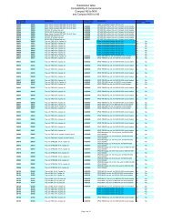
General contents Contents<br />
Contents<br />
401F_E0010TDM.indd<br />
Presentation<br />
General presentation<br />
<strong>Electric</strong>al switchboards 2<br />
up to 3200A 2<br />
Characteristics 4<br />
The forms according to IEC 61439-2 5<br />
Catalog numbers<br />
Functional units<br />
Switchgears 6<br />
Distribution<br />
Horizontal busbars 7<br />
up to 1600A 7<br />
Lateral Linergy busbars 10<br />
up to 1600A 10<br />
Lateral flat busbars 12<br />
up to 1600 A 12<br />
up to 3200 A 14<br />
Form 2 partitioning 16<br />
Form 3 partitioning 20<br />
Enclosures<br />
Cubicles, frameworks 21<br />
IP55 cover panels 23<br />
Plinth, gland plates 24<br />
Accessories 25<br />
Dimensions<br />
Cubicles 26<br />
version: 1.0 - 06/2010<br />
1
Index<br />
Index<br />
Index<br />
Cat. no. Designation Module<br />
03000<br />
03583 Universal angle brackets (6) 401E22905/6<br />
04000<br />
04502 Linergy vertical busbar, 630 A 401E22215/2<br />
04503 Linergy vertical busbar, 800 A 401E22215/2<br />
04504 Linergy vertical busbar, 1000 A 401E22215/2<br />
04505 Linergy vertical busbar, 1250 A 401E22215/2<br />
04506 Linergy vertical busbar, 1600 A 401E22215/2<br />
04516 Vertical busbar with holes, 60x5mm 401E22315/2<br />
04518 Vertical busbar with holes, 80x5mm 401E22315/2<br />
04525 Vertical busbar with holes, 50x10mm 401E22315/4<br />
04526 Vertical busbar with holes, 60x10mm 401E22315/4<br />
04528 Vertical busbar with holes, 80x10mm 401E22315/4<br />
04536 Horizontal busbar without holes, 60x5mm 401E22110/1<br />
04538 Horizontal busbar without holes, 80x5mm 401E22110/1<br />
04545 Horizontal busbar without holes, 50x10mm 401E22110/3<br />
04546 Horizontal busbar without holes, 60x10mm 401E22110/3<br />
04548 Horizontal busbar without holes, 80x10mm 401E22110/3<br />
04550 Horizontal busbar without holes, 100x10mm 401E22110/3<br />
04634 Connection plate for 5mm horizontal bar to lateral Linergy busbar, 1000A 401E22215/3<br />
04635 Connection plate for 5mm horizontal bar to lateral Linergy busbar, 1600A 401E22215/3<br />
04636 Connection plate for 10mm horizontal bar, 1600A 401E22215/3, 401E22315/5<br />
04637 Connection plate for 10mm horizontal bars to vertical flat bar, 3200A 401E22315/5<br />
04640 Joint for 50/60mm horizontal busbars 401E22110/1, 401E22110/3<br />
04641 Joint for 80/100mm horizontal busbars 401E22110/1, 401E22110/3<br />
04642 Mounting hardware for joint > 80mm 401E22215/3, 401E22315/5<br />
04645 20 screws for vertical / horizontal busbars connections 401E22315/3<br />
04651 Support for lateral vertical Linergy busbars 401E22215/3<br />
04662 Free support for 5/10mm busbars 401E22110/1, 401E22110/3, 401E22315/2,<br />
401E22315/4<br />
04664 Support for 5/10mm horizontal busbars 401E22110/1, 401E22110/3<br />
04671 Support mounting hardware for bars > 80mm 401E22110/3<br />
04678 5/10 mm busbar free support, 115 mm spacing 401E22315/2, 401E22315/4<br />
04901 Form 3 horizontal partition 401E22905/6<br />
04911 Inter-cubicle partition, D = 400 mm 401E22905/4<br />
04924 Form 2 restoration kit for side barrier cut-out 401E22905/3<br />
04943 Rear support for Form 3 partition 401E22905/6<br />
04955 Form 3 vertical partition for rear connection, 3 or 4 modules 401E22905/6<br />
04956 Form 3 vertical partition for rear connection, 5 or 6 modules 401E22905/6<br />
06000<br />
06461 20 bolts, M6 401E23120/2<br />
06501 2 uprights H2000 401E23110/2<br />
06502 2 adaptated uprights H2000 401E23110/2<br />
06503 2 uprights+intermediary H2000 401E23110/2<br />
06512 2 frames + roof W300 D500 401E23110/2<br />
06513 2 frames + roof W300 D800 401E23110/2<br />
06514 2 frames+ roof + flange W700 D500 401E23110/2<br />
06515 2 frames+ toit + flange W700 D800 401E23110/2<br />
06522 Plain door W300 401E23110/4<br />
06524 Plain door W700 401E23110/4<br />
06525 Transparent door W700 401E23110/4<br />
06533 Rear panel W300 401E23110/4<br />
06535 2 side panels D500 401E23110/4<br />
06537 Rear panel W700 401E23110/4<br />
06538 2 side panels D800 401E23110/4<br />
06540 Form 2 front back barrier W300 401E22905/4<br />
06543 Form 2 side barrier ext. to D800 401E22905/3<br />
06545 Side barrier form 2 D500 401E22905/3<br />
06555 Inter-cubicles cover D500 401E22905/4<br />
401F_E0012TDM.indd version: 1.0 - 05/2010<br />
1
Index<br />
Index<br />
Index<br />
Cat. no. Designation Module<br />
06560 Form 2 horiz. cover W300 D500 401E22905/5<br />
06563 Form 2 horz. cover W300 D500+300 401E22905/5<br />
06570 Form 2 horz. cover W700 D500 401E22905/5<br />
08000<br />
08566 Front plate support frame, W=650mm 401E23110/3<br />
08911 Earthing wire, 6mm² 401E23120/2<br />
NSY<br />
NSYAS500 Bottom support for lateral vertical busbar D500 401E22315/2, 401E22315/4<br />
NSYAS800 Bottom support for lateral vertical busbar D800 401E22315/2, 401E22315/4<br />
NSYAS800L Bottom support for lateral vertical busbar D800, 115mm spacing 401E22315/2, 401E22315/4<br />
NSYBHS500 Horizontal busbar support W300, D500 401E22110/1, 401E22110/3<br />
NSYBHS800 Horizontal busbar support W300, D800 401E22110/1, 401E22110/3<br />
NSYBHS800L Horizontal busbar support D800, 115mm spacing 401E22110/1, 401E22110/3<br />
NSYBVS500 Vertical lateral busbar support D500 401E22315/2, 401E22315/4<br />
NSYBVS800 Vertical lateral busbar support D800 401E22315/2, 401E22315/4<br />
NSYBVS800L Vertical lateral busbar support D800, 115mm spacing 401E22315/2, 401E22315/4<br />
NSYEC351 Entry cable gland plate W300 D500 401E23110/5<br />
NSYEC381 Entry cable gland plate W300 D800 401E23110/5<br />
NSYEC751 Entry cable gland plate W700 D500 401E23110/5<br />
NSYEC781 Entry cable gland plate W700 D800 401E23110/5<br />
NSYEL166D8 Earthing lead, 6mm² section, 160mm length, 8.3mm terminal 401E23120/2<br />
NSYEL3525D8 Earthing lead, 25mm² section, 350mm length, 8.3mm terminal 401E23120/2<br />
NSYSFBK19 Swing 19" rack coupling kit 401E23110/3, 401E23120/2<br />
NSYSFEB 4 lifting eyes M12 401E23120/2<br />
NSYSFELB 4 lifting brackets 401E23120/2<br />
NSYSPF3100 Front plinth 100x300 401E23110/5<br />
NSYSPF3200 Front plinth 200x300 401E23110/5<br />
NSYSPF7100 Front plinth 100x700 401E23110/5<br />
NSYSPF7200 Front plinth 200x700 401E23110/5<br />
NSYSPS5100 2 Plinth side panels 100x500 401E23110/5<br />
NSYSPS5200 2 Plinth side panels 200x500 401E23110/5<br />
NSYSPS8100 2 Plinth side panels 100x700 401E23110/5<br />
NSYSPS8200 2 Plinth side panels 200x700 401E23110/5<br />
2<br />
version: 1.0 - 05/2010 401F_E0012TDM.indd
PD391265b_SE<br />
PD391266b_SE<br />
PD391267b_SE<br />
General presentation <strong>Electric</strong>al switchboards<br />
up to 3200A<br />
Presentation<br />
The <strong>Prisma</strong> <strong>Plus</strong> functional<br />
system<br />
2<br />
PD391264b_SE<br />
The <strong>Prisma</strong> <strong>Plus</strong> functional system can be used for all types of low-voltage<br />
distribution switchboards (main, subdistribution and final) up to 3200 A, in<br />
commercial and industrial environments.<br />
Switchboard design is very simple:<br />
A metal structure<br />
The switchboard is made up of one or more frameworks combined side-by-side or<br />
back-to-back, on which a complete selection of cover panels and doors can be<br />
mounted.<br />
A distribution system<br />
Horizontal busbars or vertical busbars positioned in a lateral compartment or at the<br />
rear of the cubicle are used to distribute electricity throughout the switchboard.<br />
Complete functional units<br />
Each device is part of a functional unit comprising:<br />
b dedicated mounting plate for device installation<br />
b front plate to block direct access to live parts prefabricated busbar connections<br />
b<br />
devices for on-site connections.<br />
Each functional unit contributes to a function in the switchboard. The functional units<br />
are modular and are arranged rationally, one on top of another, within the enclosure.<br />
The system includes everything required for functional unit mounting, supply and<br />
onsite connection. The components of the <strong>Prisma</strong> <strong>Plus</strong> system and those of the<br />
functional units in particular have been designed and tested taking into account<br />
device characteristics. This design approach ensures a high degree of reliability in<br />
system operation and optimum safety for personnel.<br />
version: 1.0 - 06/2010 401F_E10020.indd
PD391269b_SE<br />
PD391270b_SE<br />
PD391271b_SE<br />
General presentation <strong>Electric</strong>al switchboards<br />
up to 3200A<br />
Presentation<br />
Advantages of <strong>PH</strong> system<br />
switchboards<br />
PD391268b_SE<br />
A safe electrical installation<br />
The total compatibility of <strong>Schneider</strong> <strong>Electric</strong> devices with the <strong>PH</strong> system is a key<br />
advantage in ensuring a high level of installation dependability.<br />
An upgradeable electrical installation<br />
Thanks to modular design, <strong>PH</strong> switchboards can be modified easily to integrate new<br />
functional units as needed. Maintenance operations, carried out with the<br />
switchboard de-energised, are fast and straight-forward due to easy access to<br />
devices.<br />
Total safety for personnel<br />
Work in a switchboard must be carried out by authorised persons in compliance with<br />
all applicable safety regulations. To increase the safety of personnel, devices are<br />
installed behind protective front plates; only the operating handles are accessible.<br />
Additional internal protection (partitions, barriers) is available to create form 2 or 3<br />
separation to protect against direct contacts with live parts.<br />
Terminal shields are mandatory for installation of Compact NSX and INS/INV<br />
devices in <strong>PH</strong> system enclosures.<br />
<strong>Electric</strong>al switchboards built using the <strong>Prisma</strong> <strong>Plus</strong> functional system and<br />
<strong>Schneider</strong> <strong>Electric</strong> recommendations fully comply with international standard<br />
IEC 61439-2.<br />
401F_E10020.indd version: 1.0 - 06/2010<br />
3
General presentation<br />
Presentation<br />
4<br />
PD391272b_SE<br />
Characteristics<br />
<strong>Electric</strong>al characteristics<br />
Use of the components in the <strong>Prisma</strong> <strong>Plus</strong> functional system ensures the creation of<br />
switchboards complying with standards IEC 50298, EN 50298, IEC 61439-2 and<br />
EN 61439-2, as well as local versions with the following electrical characteristics:<br />
b rated insulation level of main busbars: 1000 V<br />
b rated operational current Ie: 3200 A<br />
b rated peak withstand current Ipk: 187 kÂ<br />
b rated short-time withstand current Icw: 85 kA rms/1 second<br />
b frequency: 50/60 Hz.<br />
Mechanical characteristics<br />
b Steel sheet metal.<br />
b Electrophoresis treatment + hot-polymerised polyester epoxy powder.<br />
b White colour RAL 9001.<br />
b Can be dismantled.<br />
b Can be combined side-by-side and back-to-back.<br />
b Degree of protection: IP55.<br />
b Degree of protection against mechanical impacts: IK10 with door.<br />
b Framework dimensions:<br />
v two widths:<br />
- W 300: cable compartment<br />
- W 700: device compartment or cable compartment<br />
v two depths: 500, 800 mm<br />
v height: 2000 mm<br />
b Indoor cubicles.<br />
version: 1.0 - 06/2010 401F_E10020.indd
E33522<br />
E33523<br />
General presentation<br />
Presentation<br />
Decisions concerning the Form of separation and the<br />
degree of protection are the subject of an agreement<br />
between the manufacturer and the user.<br />
Form 2b.<br />
Form 3b.<br />
The forms according<br />
to IEC 61439-2<br />
In most installations, <strong>Prisma</strong> <strong>Plus</strong> cubicles do not require partitioning. In this case,<br />
the switchboard is a Form 1.<br />
Safety being one of its foremost goals, <strong>Schneider</strong> <strong>Electric</strong> offers options and features<br />
that go well beyond the recommendations of the standard.<br />
The protection of life and property is a standard feature due to:<br />
b front plates that require a tool to be removed<br />
b keylocks on doors, some of which provide access to live parts<br />
b the systematic installation of terminal shields on Compact NSX circuit breakers<br />
and Interpact INS and INV switch-disconnectors<br />
b covering of the upstream and downstream terminals on the incoming device so<br />
that operators are perfectly safe at all points in the switchboard when the incoming<br />
device is off (open).<br />
What is more, <strong>Prisma</strong> <strong>Plus</strong> offers different levels of partitioning to create separations<br />
inside the cubicles and thus create Form 2, 3 electrical switchboards.<br />
<strong>Electric</strong>al switchboards must meet the degree of protection IP2X to comply with<br />
standard IEC 61439-2<br />
Form 2<br />
<strong>PH</strong> <strong>System</strong> offers Form 2 cubicles<br />
It is a physical separation of horizontal, vertical busbars from the functional units,<br />
complying with standard IEC 61439-2<br />
Form 3b<br />
<strong>PH</strong> <strong>System</strong> offers Form 3b cubicles. They are achieved by separating from one<br />
another the functional units of a Form 2 switchboard.<br />
Device must be equipped of downstream terminal shields.<br />
401F_E10020.indd version: 1.0 - 06/2010<br />
5
DD384395<br />
Functional units<br />
Catalogue numbers<br />
Intermediaire uprights.<br />
2<br />
Switchgears<br />
Upgraduable <strong>Prisma</strong> <strong>Plus</strong> functional units<br />
Functional units include switchgear mounting plates, front plates, connectors,<br />
connections, connection supports, barriers...<br />
Switchgear Cat. no.<br />
Masterpact NW 08 to NW 32 400E21100<br />
Masterpact NT 06 to NT 16 400E21110<br />
Compact NS up to 1600 400E21120<br />
Compact NS from 630 to 1600 400E21130<br />
Compact NSX up to 630 400E21150<br />
Interpact INS-INV250-630 400E21200<br />
Interpact INS-INV630-2500 400E21210<br />
Source changeover systems Compact/Masterpact 400E21160<br />
Source changeover systems Interpact INS 400E21250<br />
Acti 9 400E21400<br />
Accessories 400E21500-<br />
400E21600<br />
version: 1.0 - 06/2010 401F_E21000.indd
DD384396<br />
DD384397<br />
DD384398<br />
Distribution<br />
Catalogue numbers<br />
The bars are secured by insulated supports attached to<br />
the framework.<br />
The tables opposite indicate:<br />
b the number and size of the bars to be used,<br />
depending on the permissible current level in the<br />
busbars<br />
b the number of busbar supports for each type of<br />
framework, depending on:<br />
v the size of the busbars<br />
v the rated short-time withstand current Icw.<br />
For more information on busbar calculations, see<br />
DESW016.<br />
The modularity of the busbar is 3 modules.<br />
Fixed support and free support.<br />
Joints.<br />
NYBSHS500<br />
DD381226<br />
Horizontal busbars<br />
Up to 1600 A<br />
Flat copper bars 5 mm thick<br />
Busbar calculation<br />
Number and size of copper busbars<br />
Permissible current (A) No. of bars/phase<br />
IP55<br />
750 1 bar 60 x 5<br />
900 1 bar 80 x 5<br />
1250 2 bars 60 x 5<br />
1600 2 bars 80 x 5<br />
Note: the permissible current values for the busbars are given for an ambient temperature of<br />
35 °C around the switchboard.<br />
Number of supports<br />
Framework width Size of bars (mm) No. of supports lcw (kA rms/1 s)<br />
(mm)<br />
y 15 y 25 y 30 y 40 y 50<br />
W 700 mm 1 bar 60 x 5<br />
1 bar 80 x 5<br />
2 bars 60 x 5<br />
2 bars 80 x 5<br />
2 3<br />
W 300 mm All sizes 1 2<br />
Busbar selection<br />
Flat busbars, W 2000 mm<br />
Designation Cat. no.<br />
Copper bar without holes, 60 x 5 04536<br />
Copper bar without holes, 80 x 5 04538<br />
Busbar supports<br />
Two fixed supports for 700 mm wide frameworks and one fixed support for 300 mm<br />
wide frameworks are mandatory. If more supports are required, use free supports.<br />
Designation Cubicle W 700 Cubicle W 300<br />
D 500 D 500 D 800<br />
Distance between busbar centres 75 75 75<br />
Fixed support for horizontal bars 04664 NSYBHS500 NSYBHS800<br />
Free support (additional) 04662 04662 04662<br />
04664 04662<br />
Joints<br />
Designation Cat. no.<br />
1 joint for bars W 60 mm 04640<br />
W 80 mm 04641<br />
Note: when installed at the bottom of cubicles, the busbars must be partitioned, see<br />
page 401F22905.indd/2.<br />
401F_E22110.indd version: 1.0 - 06/2010<br />
1<br />
DD381225
DD384396<br />
Distribution<br />
Catalogue numbers<br />
The bars are secured by insulated supports attached to<br />
the framework.<br />
The tables opposite indicate:<br />
b the number and size of the bars to be used,<br />
depending on the permissible current level in the<br />
busbars<br />
b the number of busbar supports for each type of<br />
framework, depending on:<br />
v the size of the busbars<br />
v the rated short-time withstand current Icw.<br />
For more information on busbar calculations, see<br />
DESW016.<br />
The modularity of the busbar is 3 modules.<br />
2<br />
Horizontal busbars<br />
Up to 3200 A<br />
Flat copper bars 10 mm thick<br />
Busbar calculation<br />
Number and size of copper busbars<br />
Permissible current (A) No. of bars/phase<br />
IP55<br />
1080 1 bar de 50 x 10<br />
1250 1 bar de 60 x 10<br />
1600 1 bar de 80 x 10<br />
1850 2 bars de 50 x 10<br />
2000 2 bars de 60 x 10<br />
2500 2 bars de 80 x 10<br />
2900 2 bars de 100 x 10<br />
Note: the permissible current values for the busbars are given for an ambient temperature of<br />
35 °C around the switchboard.<br />
Number of supports (distance between centres: 75 mm)<br />
Framework width<br />
(mm)<br />
Size of bars<br />
(mm)<br />
No. of supports Icw (kA rms/1 s)<br />
y 25 y 30 y 40 y 50 y 60 y 65 y 75 y 85<br />
W 700 mm 1 bar de 50 x 10<br />
1 bar de 60 x 10<br />
1 bar de 80 x 10<br />
3<br />
4<br />
2 bars de 50 x 10<br />
2 bars de 60 x 10<br />
2 bars de 80 x 10<br />
2 bars de 100 x 10<br />
2<br />
W 300 mm All sizes 1 2<br />
Number of supports (distance between centres: 115 mm)<br />
Framework width<br />
(mm)<br />
Size of bars<br />
(mm)<br />
No. of supports Icw (kA rms/1 s)<br />
y 25 y 30 y 40 y 50 y 60 y 65 y 75 y 85<br />
W 700 mm 1 bar de 50 x 10<br />
1 bar de 60 x 10<br />
1 bar de 80 x 10<br />
2 bars de 50 x 10<br />
2 bars de 60 x 10<br />
2 bars de 80 x 10<br />
2 bars de 100 x 10<br />
2<br />
3 4<br />
W 300 mm All sizes 1 2<br />
version: 1.0 - 06/2010 401F_E22110.indd
DD384397<br />
DD384398<br />
Distribution<br />
Catalogue numbers<br />
Fixed support and free support.<br />
Joints.<br />
NYBSHS500<br />
DD381226<br />
Horizontal busbars<br />
Up to 3200 A<br />
Flat copper bars 10 mm thick<br />
Busbar selection<br />
Flat busbars, W 2000 mm<br />
Designation Cat. no.<br />
Copper bar without holes 50 x 10 04545<br />
Copper bar without holes 60 x 10 04546<br />
Copper bar without holes 80 x 10 04548<br />
Copper bar without holes 100 x 10 04550<br />
Busbar supports<br />
Two fixed supports for 700 mm wide frameworks and one fixed support for 300 mm<br />
wide frameworks are mandatory. If more supports are required, use free supports.<br />
Designation Bar width Cubicle W 700 Cubicle W 300<br />
Distance between<br />
busbar centres<br />
Fixed support for<br />
horizontal bars<br />
Free support<br />
(additional) for<br />
bars<br />
D 500 D 800<br />
75 75 75<br />
y 80 mm 04664 NSYBHS500 NSYBHS800<br />
> 80 mm 04664 +<br />
04671<br />
401F_E22110.indd version: 1.0 - 06/2010<br />
3<br />
DD381225<br />
NSYBHS500 +<br />
04671<br />
y 80 mm 04662 04662 04662<br />
> 80 mm 04662 +<br />
04671<br />
Designation Bar width Cubicle W 700<br />
D 800<br />
Distance between<br />
busbar centres<br />
Fixed support for<br />
horizontal bars<br />
Free support<br />
(additional) for<br />
bars<br />
04662 +<br />
04671<br />
115 115<br />
NSYBHS800 +<br />
04671<br />
04662 +<br />
04671<br />
Cubicle W 300<br />
D 800<br />
y 80 mm NSYBHS800L NSYBHS800L<br />
> 80 mm NSYBHS800L<br />
+ 04671<br />
y 80 mm 04678 04678<br />
> 80 mm 04678 +<br />
04671<br />
04664 04662<br />
Joints<br />
NSYBHS800L<br />
+ 04671<br />
04678 +<br />
04671<br />
Designation Cat. no.<br />
1 joint for bars Width 50 and 60 mm 04640<br />
Width 80 and 100 mm 04641<br />
Note: when installed at the bottom of cubicles, the busbars must be partitioned, see<br />
page 401F22905.indd/5.
PD391273b_SE<br />
Distribution<br />
Catalogue numbers<br />
The table opposite indicates:<br />
b the catalogue numbers of the bars to be used,<br />
depending on the permissible current level<br />
in the busbars<br />
b the number of supports required, depending<br />
on the rated short-time withstand current<br />
(Icw in kA rms/1 s).<br />
For more information on other ambient temperatures,<br />
see DESW016.<br />
Busbars up to 1600 A.<br />
The bottom support also maintains the bars in position.<br />
2<br />
DD381233<br />
DD381236<br />
Lateral Linergy busbars<br />
up to 1600 A - depth 500 mm<br />
Busbar calculation<br />
Linergy<br />
busbars<br />
Cat. no. Permissible<br />
current<br />
at 35 °C for<br />
switchboard<br />
DD381234<br />
DD381237<br />
No. of supports Icw (kA rms/1 s)<br />
IP55 y 25 y 30 y 40 y 50 y 60 y 65 y 75 y 85<br />
Linergy 630 04502 590<br />
Linergy 800 04503 760<br />
Linergy 1000<br />
Linergy 1250<br />
Linergy 1600<br />
04504<br />
04505<br />
04506<br />
950<br />
1170<br />
1480<br />
3<br />
4 5<br />
7 8<br />
Note: The permissible current values for the busbars are given for an ambient temperature of<br />
35 °C around the switchboard. The bottom support also maintains the bars in position. Each<br />
catalogue number represents one bar.<br />
Busbar selection<br />
Linergy busbars, W 1670 mm<br />
Cat. no. selection: see the table below.<br />
Each bar is supplied with a stop for the bottom support:<br />
Bar 630 A.<br />
Cat. no. 04502<br />
Bar 1250 A.<br />
Cat. no. 04505<br />
Bar 800 A.<br />
Cat. no. 04503<br />
Bar 1600 A.<br />
Cat. no. 04506<br />
version: 1.0 - 06/2010 401F_E22215.indd<br />
DD381235<br />
Bar 1000 A.<br />
Cat. no. 04504
DD384399<br />
DD384400<br />
DD384401<br />
Distribution<br />
Catalogue numbers<br />
Single Linergy busbars up to 1600 A.<br />
Connection 04635 to horizontal busbars, 5 mm thick.<br />
Connection 04636 to horizontal busbars, 10 mm thick.<br />
06502<br />
04651<br />
DD380741<br />
Lateral Linergy busbars<br />
up to 1600 A - depth 500 mm<br />
Busbar supports<br />
Supports are used to install busbars to the left or right of the device zone. They are<br />
supplied with 8.8 class mounting hardware.<br />
Designation Cat. no.<br />
Busbar supports 04651<br />
401F_E22215.indd version: 1.0 - 06/2010<br />
3<br />
DD380742<br />
Busbar supports. Each bar is supplied with a stop for installation<br />
on the bottom support.<br />
Horizontal-busbar connections<br />
These connections are used to connect horizontal busbars, 75 mm centre distance,<br />
5 or 10 mm thick, to lateral Linergy busbars.<br />
Supplied with mounting hardware.<br />
Designation Cat. no.<br />
Connection to horizontal busbars,<br />
5 mm thick<br />
Connection to horizontal busbars,<br />
10 mm thick<br />
1000 A connection 04634<br />
1600 A connection 04635<br />
width of horizontal bars y 80 mm 04636<br />
width or horizontal bars > 80 mm 04636 + 04642
DD384402<br />
DD384403<br />
Distribution<br />
Catalogue numbers<br />
The bars are secured by insulated supports. Three<br />
fixed supports, attached to the framework, are<br />
mandatory.<br />
If necessary, additional free supports may be used.<br />
The bars rest on a bottom support.<br />
The table opposite indicates:<br />
b the number and size of the bars to be used,<br />
depending on the permissible current level in the<br />
busbars<br />
b the number of supports required in a cubicle,<br />
depending on the rated short-time withstand current<br />
(Icw).<br />
The bars are secured by three mandatory fixed supports and<br />
two free supports.<br />
2<br />
NSYBVS500<br />
NSYAS500<br />
04662<br />
DD383350<br />
DD383352<br />
Lateral flat busbars<br />
up to 1600 A<br />
Busbars 5 mm thick<br />
Busbar calculation<br />
Permissible current<br />
for switchboards<br />
No. of bars/phase No. of supports Icw (kA rms/1 s)<br />
IP55 y 15 y 25 y 30 y 40 y 50<br />
750 1 bar de 60 x 5<br />
900<br />
1250<br />
1 bar de 80 x 5<br />
2 bars de 60 x 5<br />
3<br />
5<br />
7<br />
1600 2 bars de 80 x 5<br />
Note: The permissible current values for the busbars are given for an ambient temperature of<br />
35 °C around the switchboard.<br />
For more information on busbar calculations, see DESW016.<br />
Busbar selection<br />
Flat busbars, W 1675 mm<br />
Designation Cat. No.<br />
Copper bar with holes 60 x 5 04516<br />
Copper bar with holes 80 x 5 04518<br />
Busbar supports<br />
Three fixed supports are required to maintain the busbars. If more than three<br />
supports are required, use additional free supports.<br />
Designation Cubicle W 300<br />
D 500 D 800<br />
Distance between<br />
busbar centres<br />
Fixed support for lateral<br />
flat busbars<br />
75 75 115<br />
NSYBVS500 NSYBVS800 NSYBVS800L<br />
Free support (additional) 04662 04662 04678<br />
NSYBVS500. 04662.<br />
Busbar chocks<br />
The bottom support maintains the bars in position. It is not considered a busbar<br />
support.<br />
Designation Cubicle W 300<br />
D 500 D 800<br />
Distance between<br />
busbar centres<br />
75 75 115<br />
Bottom support for lateral NSYAS500<br />
flat busbars<br />
NSYAS800 NSYAS800L<br />
NSYAS500.<br />
DD381650<br />
version: 1.0 - 06/2010 401F_E22315.indd
DD384405<br />
DD384406<br />
DD383399<br />
Distribution<br />
Catalogue numbers<br />
To satisfy safety clearances, the assembly points on adjacent<br />
bars must be staggered as shown above.<br />
401F_E22315.indd<br />
DD380512<br />
DD383398<br />
Lateral flat busbars<br />
up to 1600 A<br />
Busbars 5 mm thick<br />
Horizontal-busbar connections<br />
Direct connection (115 mm between centres)<br />
The connection between horizontal busbars, 5 mm thick, and lateral flat busbar is<br />
direct, after drilling the bars.<br />
Drilling diagram for horizontal busbars, 5 mm thick.<br />
Direct connection (75 mm between centres)<br />
For busbars with 75 mm between centres, the bars must fully overlap.<br />
Drilling diagram for horizontal busbars, 5 mm thick<br />
Number of assembly screws (04645)<br />
Horizontal bars (mm) Vertical bars (mm)<br />
50 60 80<br />
50 2 2 2<br />
60 - 2 2<br />
80 - - 3<br />
In case of direct connection (75 or 115 mm centre distance) with a horizontal<br />
busbars, bottom support part no. NSYAS500, NSYAS800 or NSYAS800L are not<br />
required.<br />
version: 1.0 - 06/2010<br />
3
DD384402<br />
DD384403<br />
Distribution<br />
Catalogue numbers<br />
The bars are secured by insulated supports. Three<br />
fixed supports, attached to the framework, are<br />
mandatory. If necessary, additional free supports may<br />
be used.<br />
The bars rest on a bottom support.<br />
The table opposite indicates:<br />
b the number and size of the bars to be used,<br />
depending on the permissible current level in the<br />
busbars<br />
b the number of supports required in a cubicle,<br />
depending on the rated short-time withstand current<br />
(Icw).<br />
Above 1600 A, the busbars must be doubled and<br />
installed in two busbar sections, side by side. In this<br />
case, they must be interconnected by three<br />
equipotential links.<br />
The bars are secured by three mandatory fixed supports and<br />
two free supports.<br />
Busbars up to 3200 A.<br />
4<br />
NSYBVS500<br />
NSYAS500<br />
04662<br />
DD381505<br />
DD383350<br />
DD383352<br />
Lateral flat busbars<br />
up to 3200 A<br />
Busbars 10 mm thick<br />
Busbar calculation<br />
Permissible current No. of bars/ No. of supports Icw (kA rms/1 s)<br />
for switchboards phase<br />
IP55 25 30 40 50 60 65 75 85<br />
1080 1 bar 50 x 10<br />
1250<br />
1600<br />
1 bar, 60 x 10<br />
1 bar, 80 x 10<br />
5 7<br />
9<br />
1850 2 bars, 50 x 10 3<br />
2000 2 bars, 60 x 10<br />
2500 2 bars, 80 x 10<br />
3200 2 bars, 100 x 10<br />
Note: The permissible current values for the busbars are given for an ambient temperature of<br />
35 °C around the switchboard.<br />
For more information on busbar calculations, see DESW016<br />
Busbar selection<br />
Flat busbars, W 1675 mm<br />
Designation Cat. no.<br />
Copper bar with holes 50 x 10 04525<br />
Copper bar with holes 60 x 10 04526<br />
Copper bar with holes 80 x 10 04528<br />
Busbar supports : directly fixed on frame (300 mm width duct)<br />
Three fixed supports are required to maintain the busbars. If more than 3 supports<br />
are required, use additional free supports.<br />
Designation Cubicle W 300<br />
D 500 D 800 D 800<br />
Distance between busbar<br />
centres<br />
Fixed support for lateral flat<br />
busbars<br />
75 75 115<br />
NSYBVS500 NSYBVS800 NSYBVS800L<br />
Free support (additional) 04662 04662 04678<br />
NSYBVS500. 04662.<br />
Busbar chocks<br />
The bottom support maintains the bars in position. It is not considered a busbar<br />
support.<br />
Designation Cubicle W 300<br />
D 500 D 800<br />
Distance between busbar<br />
centres<br />
Bottom support for lateral flat<br />
busbars<br />
NSYAS500.<br />
DD381650<br />
75 75 115<br />
NSYAS500 NSYAS800 NSYAS800L<br />
version: 1.0 - 06/2010 401F_E22315.indd
DD384404<br />
DD384405<br />
DD384406<br />
DD383399<br />
Distribution<br />
Catalogue numbers<br />
To satisfy safety clearances, the assembly points on adjacent<br />
bars must be staggered as shown above.<br />
401F_E22315.indd<br />
DD383367<br />
DD383400<br />
Lateral flat busbars<br />
up to 3200 A<br />
Busbars 10 mm thick<br />
Horizontal busbars connection<br />
Connection with a horizontal busbars, 10 mm thick.<br />
In this case, use the bottom support ref. NSYAS500, NSYAS800 or NSYAS800L.<br />
Designation Horizontal Vert. Cat. no.<br />
Busbars Busbars<br />
Connection vert. busbars (1 bar/phase) with W y 80 mm 50/60 mm 04636<br />
horizontal bars<br />
W > 80 mm 50/60 mm 04636 + 04642<br />
W y 80 mm 80 mm 04637<br />
W > 80 mm 80 mm 04637 + 04642<br />
Connection vert. busbars (2 bars/phase) with W y 80 mm 50/80 mm 04637<br />
horizontal bars<br />
W > 80 mm 50/80 mm 04637 + 04642<br />
Direct connection (115 mm centre distance)<br />
The connection between horizontal busbars, 10 mm thick, and lateral flat busbar is<br />
direct, after drilling the bars.<br />
Drilling diagram for horizontal busbars, 10 mm thick.<br />
Direct connection (75 mm centre distance)<br />
For busbars with 75 mm between centres, the bars must fully overlap.<br />
Drilling diagram for horizontal busbars, 10 mm thick.<br />
Number of assembly screws no. 04645<br />
Horizontal bars (mm) Vertical bars (mm)<br />
50 60 80 100<br />
50 2 2 2 2<br />
60 - 2 2 2<br />
80 - - 3 3<br />
In case of direct connection (75 or 115 mm centre distance) with a horizontal<br />
busbars, bottom support part no. NSYAS500, NSYAS800 or NSYAS800L are not<br />
required.<br />
version: 1.0 - 06/2010<br />
5
Distribution<br />
Catalogue numbers<br />
2<br />
PD391274b_SE<br />
Form 2 partitioning<br />
Separation of busbars from the functional units. Configuration Form 2<br />
Form 2 partitioning is essential to ensure excellent protection for the installation and<br />
operators working in the switchboard.<br />
When added to standard protection features (terminal shields, prefabricated<br />
connections, etc.), it eliminates the risk of direct contacts with live parts. <strong>Prisma</strong> <strong>Plus</strong><br />
offers Form 2b.<br />
Form 2b provides much better safety than Form 2a, notably during connection,<br />
because the terminals are separated from the busbars.<br />
version: 1.0 - 06/2010 401F_E22905.indd
DD384407<br />
DD384408<br />
Distribution<br />
Catalogue numbers<br />
06545.<br />
06543.<br />
DD383356<br />
DD384441<br />
Form 2 partitioning<br />
Partitioning of lateral vertical busbars<br />
Lateral partitioning<br />
b<br />
b<br />
b<br />
v<br />
v<br />
b<br />
Vertical barrier made of insulating slats.<br />
Can be installed on both sides of Linergy and flat busbars.<br />
Made up of:<br />
five extruded slats that clip to the supports<br />
two metal plates at the top and bottom that can be cut out to pass a PE or PEN.<br />
The space between the slats is sufficient for prefabricated connections (one<br />
copper bar, 5 or 10 mm thick, or insulated flexible bars) or for cables up to 35 mm²,<br />
while maintaining the degree of protection IP2X compliance with standard IEC<br />
60695.2.1 concerning withstand to fire.<br />
Form 2 restoration for side-barrier cut-out<br />
This kit enables passage of the connection between a device > 1600 A (NW, INS)<br />
and lateral vertical busbars.<br />
It is made up of an insulated plate (six modules H 300 mm) that can be cut as<br />
required, supplied with supports and the necessary hardware.<br />
It can be installed at any height in the switchboard.<br />
Cat. no. selection<br />
Designation Cat. no.<br />
Form 2 side barrier for D 500 mm cubicle 06545<br />
Form 2 restoration kit 04924<br />
Partitioning extension<br />
For the <strong>PH</strong> system switchboards 800 mm depth (500 + 300), a partitioning extension<br />
for 300 mm depth is required.<br />
Designation Cat. no.<br />
Partitioning extension in 800 mm depth 06543<br />
401F_E22905.indd version: 1.0 - 06/2010<br />
3
DD384409<br />
DD384410<br />
Distribution<br />
Catalogue numbers<br />
06540.<br />
06555.<br />
4<br />
DD383360<br />
DD383362<br />
Form 2 partitioning<br />
Front and rear barrier<br />
Barrier, W 300 mm, from top to bottom of the cubicle.<br />
Can be installed in the front and rear of the busbar compartment.<br />
Protects against direct contact with the busbars.<br />
Front protection<br />
Is realized by the association of the door W 300 mm and this barrier. Metallic barrier,<br />
composed of 2 parts H 850mm, pre-cut at both ends.<br />
Rear protection<br />
A barrier is required at the rear of the busbar compartment in cubicles that are 800,<br />
1000 and 1300 mm deep.<br />
Cat. no. selection<br />
Designation Cat. no.<br />
Front or rear barrier for lateral vertical busbars W 300 mm 06540<br />
Inter-cubicle partitioning<br />
Metal partition, used to separate two adjacent cubicles.<br />
It is made up of two panels, each 850 mm high.<br />
The top and bottom ends have knock-outs for horizontal busbars.<br />
Supplied with the necessary supports and hardware, the partition is mounted on the<br />
framework and does not hinder installation of the functional mounting plates<br />
Cat. no. selection<br />
Designation Cat. no.<br />
Inter-cubicle<br />
partitioning<br />
D 500 mm 06555<br />
D 800 mm 04911 + 06543<br />
version: 1.0 - 06/2010 401F_E22905.indd
DD384412<br />
DD384411<br />
Distribution<br />
Catalogue numbers<br />
Form 2 partitioning<br />
Partitioning of horizontal busbars<br />
Set of two barriers (front and rear), plus a slotted rear panel for efficient natural<br />
convection in the switchboard.<br />
The set can be used to partition horizontal busbars installed at the top or bottom of<br />
the cubicle.<br />
The space required for the busbars is not increased.<br />
Cat. no. selection<br />
Designation Cat. no.<br />
W 300 mm D 500 mm 06560<br />
D 800 mm 06563<br />
W 700 mm D 500 mm 06570<br />
D 800 mm<br />
Note: when the busbars are at the bottom of the cubicle, gland plates are mandatory.<br />
401F_E22905.indd version: 1.0 - 06/2010<br />
5
DD384420<br />
DD384421<br />
Distribution<br />
Catalogue numbers<br />
04901 + 04943.<br />
6<br />
DD384422<br />
DD383396<br />
Form 3 partitioning<br />
Form 3 partitioning<br />
Front connection<br />
Presentation<br />
A horizontal metal partition can be used to physically separate functional units from<br />
one another.<br />
It is fixed at the rear by a support (two uprights) secured to the framework (500 mm<br />
deep) or to the intermediate uprights (800 mm deep frameworks).<br />
A set of brackets can be used to install partial Form 3 partitioning in the cubicle.<br />
It does not take up any useful space in the switchboard.<br />
Cat. no. selection<br />
Designation Cat. no.<br />
Horizontal metal partition, W 650 mm 04901<br />
Rear support for partitions, W 650 mm 04943<br />
6 universal angle brackets 03583<br />
Rear connection<br />
Presentation<br />
For rear connection, in addition to the horizontal partitions, vertical partitions are<br />
required at the rear of each functional unit.<br />
There are two heights:<br />
b 3 to 4 modules<br />
b 5 to 6 modules.<br />
Cat. no. selection<br />
Designation Cat. no.<br />
Vertical partitions (two cat. no. per<br />
functional unit)<br />
Vertical partitions for rear connected Compact NSX250.<br />
3 to 4 modules 04955<br />
5 to 6 modules 04956<br />
version: 1.0 - 06/2010 401F_E22905.indd
DD384414<br />
DD384413<br />
Enclosures<br />
Catalogue numbers<br />
06502 x 2 + 06514.<br />
06502 + 06503 + 06515.<br />
2<br />
Cubicles, frameworks<br />
700 mm wide, 500 mm deep framework<br />
Designation Cat. no.<br />
2 x 2 adapted uprights H 2000 06502 x 2<br />
2 frames + 2 flanges + 1 roof 06514<br />
b<br />
v<br />
v<br />
v<br />
v<br />
v<br />
b<br />
Composition of catalogue numbers:<br />
2 frames<br />
2 flanges<br />
mounting hardware<br />
4 uprights<br />
1 roof.<br />
Roof characteristics:<br />
- equipped with a factory-mounted polyurethane (PUR) gasket<br />
- supplied with mounting hardware<br />
- with markings for clear identificatuion of cable-running zones<br />
b<br />
b<br />
b<br />
The cables compartment can be mounted on the right or left.<br />
Can be combined side-by-side or back-to-back.<br />
Receive the IP55 cover panels.<br />
An earthing braid (NSYEL166D8 or NSYEL3525D8) must be installed between the<br />
roof and the frame.<br />
700 mm wide, 800 mm deep framework<br />
Designation Cat. no.<br />
2 adapted uprights H 2000 06502<br />
2 uprights + 2 intermediary uprights H 2000 06503<br />
2 frames + 2 flanges + 1 roof 06515<br />
b<br />
v<br />
v<br />
v<br />
v<br />
v<br />
b<br />
-<br />
-<br />
-<br />
b<br />
b<br />
b<br />
Composition of catalogue numbers:<br />
2 frames<br />
2 flanges<br />
mounting hardware<br />
4 uprights + intermediary uprights<br />
1 roof.<br />
Roof characteristics:<br />
equipped with a factory-mounted polyurethane (PUR) gasket<br />
supplied with mounting hardware<br />
with markings for clear identificatuion of cable-running zones.<br />
The cables compartment can be mounted on the right or left.<br />
Can be combined side-by-side or back-to-back.<br />
Receive the IP55 cover panels.<br />
An earthing braid (NSYEL166D8 or NSYEL3525D8) must be installed between the<br />
roof and the frame.<br />
version: 1.0 - 06/2010 401F_E23110.indd
DD384415<br />
DD384416<br />
Enclosures<br />
Catalogue numbers<br />
06501 x 2 + 06512.<br />
06501 + 06502 + 06512.<br />
401F_E23110.indd<br />
Cubicles, frameworks<br />
300 mm wide, 500 mm deep framework<br />
Designation Cat. no.<br />
2 x 2 uprights H 2000 06501 x 2<br />
2 frames + 1 roof W 300 D 500 06512<br />
b<br />
v<br />
v<br />
v<br />
v<br />
b<br />
Composition of catalogue numbers:<br />
2 frames<br />
mounting hardware<br />
4 uprights<br />
1 roof.<br />
Roof characteristics:<br />
- equipped with a factory-mounted polyurethane (PUR) gasket<br />
- supplied with mounting hardware<br />
- with markings for clear identificatuion of cable-running zones.<br />
b<br />
b<br />
b<br />
The cables compartment can be mounted on the right or left.<br />
Can be combined side-by-side or back-to-back.<br />
Receive the IP55 cover panels.<br />
An earthing braid (NSYEL166D8 or NSYEL3525D8) must be installed between the<br />
roof and the frame.<br />
300 mm wide, 500 mm deep framework for Linergy<br />
Designation Cat. no.<br />
2 uprights H 2000 06501<br />
2 adapted uprights H 2000 06502<br />
2 frames + 1 roof W 300, D 500 06512<br />
b<br />
v<br />
v<br />
v<br />
v<br />
b<br />
Composition of catalogue numbers:<br />
2 frames<br />
mounting hardware<br />
2 adapted uprights<br />
1 roof.<br />
Roof characteristics:<br />
- equipped with a factory-mounted polyurethane (PUR) gasket<br />
- supplied with mounting hardware<br />
- with markings for clear identificatuion of cable-running zones.<br />
b<br />
b<br />
b<br />
The cables compartment can be mounted on the right or left.<br />
Can be combined side-by-side or back-to-back.<br />
Receive the IP55 cover panels.<br />
An earthing braid (NSYEL166D8 or NSYEL3525D8) must be installed between the<br />
roof and the frame.<br />
300 mm wide, 800 mm deep framework<br />
Designation Cat. no.<br />
2 x 2 uprights H 2000 06501 x 2<br />
2 frames + 1 roof W 300, D 800 06513<br />
b<br />
v<br />
v<br />
v<br />
v<br />
b<br />
Composition of catalogue numbers:<br />
2 frames<br />
mounting hardware<br />
4 uprights<br />
1 roof.<br />
Roof characteristics:<br />
- equipped with a factory-mounted polyurethane (PUR) gasket<br />
- supplied with mounting hardware<br />
- with markings for clear identificatuion of cable-running zones.<br />
b<br />
b<br />
b<br />
The cables compartment can be mounted on the right or left.<br />
Can be combined side-by-side or back-to-back.<br />
Receive the IP55 cover panels.<br />
An earthing braid (NSYEL166D8 or NSYEL3525D8) must be installed between the<br />
roof and the frame.<br />
version: 1.0 - 06/2010<br />
3
DD384417<br />
DD384418<br />
DD384419<br />
Enclosures<br />
Catalogue numbers<br />
4<br />
Cubicles, frameworks<br />
Hinged front plate support frame<br />
Designation Cat. no.<br />
Hinged front plate support frame, W 700 mm 08566<br />
b Reversible for left or right-hand opening.<br />
b Secured at two points.<br />
b Can be mounted on 700 mm wide cubicles.<br />
Framework combinations<br />
The <strong>PH</strong> system frameworks can be combined side-by-side or back-to-back.<br />
A combination kit is required.<br />
Side-by-side or back-to-back (1) combination<br />
The mechanical connection between the two frames is realised with the combination<br />
kit , which comprises the IP55 sealing kit .<br />
Designation Cat. no.<br />
Swing 19” rack coupling kit NSYSFBK19<br />
(1) Back to back association must be shipped individually and combined during on-site<br />
installation.<br />
version: 1.0 - 06/2010 401F_E23110.indd
DD384423<br />
DD384424<br />
DD384425<br />
Enclosures<br />
Catalogue numbers<br />
06525.<br />
06537.<br />
06535.<br />
401F_E23110.indd<br />
IP55 cover panels<br />
Front panel<br />
W 700 mm door<br />
Designation Cat. no.<br />
Plain door W 300 mm 06522<br />
W 700 mm 06524<br />
Transparent door W 700 mm 06525<br />
b<br />
b<br />
b<br />
Equipped with a factory-mounted polyurethane (PUR) gasket.<br />
Reversible for left or right-hand opening.<br />
Equipped with a black handle and keylock (key 405).<br />
An earthing wire (08911) must be installed between the door and the frame.<br />
To connect it, a M6 captive nut from the set cat. no. 06461 is required.<br />
Rear panel<br />
Rear panel<br />
Designation Cat. no.<br />
Rear panel W 300 mm 06533<br />
W 700 mm 06537<br />
b<br />
b<br />
b<br />
Equipped with a factory-mounted polyurethane (PUR) gasket.<br />
Supplied with mounting hardware.<br />
One-piece, reinforced panel designed to ensure the degree of protection.<br />
An earthing braid (NSYEL166D8 or NSYEL3525D8) must be installed between the<br />
rear panel and the frame.<br />
Side panel<br />
Side panel<br />
Designation Cat. no.<br />
Set of two side panels D 500 mm 06535<br />
D 800 mm 06538<br />
b Equipped with a factory-mounted polyurethane (PUR) gasket.<br />
b Supplied with mounting hardware.<br />
An earthing braid (NSYEL166D8 or NSYEL3525D8) must be installed between the<br />
lateral panels and the frame.<br />
version: 1.0 - 06/2010<br />
5
DD384428<br />
DD384427<br />
Enclosures<br />
Catalogue numbers<br />
NSYSPF7100 + NSYSPS5100.<br />
NSYEC751.<br />
6<br />
Plinth, gland plates<br />
Plinth, H 100 mm and 200 mm<br />
The plinth is made up of two catalogue numbers:<br />
b one catalogue number comprising four corner posts + two cross-pieces (front and<br />
rear), that can be used in side-by-side combinations or stacked to form a plinth 200<br />
mm high (maximum)<br />
b one catalogue number comprising two side plates (500 or 800 mm).<br />
Each catalogue number is supplied with the necessary hardware.<br />
Width Depth Plinth H 100 Plinth H 200<br />
Front and<br />
rear crosspieces<br />
Lateral crosspieces<br />
Front and rear<br />
cross-pieces<br />
Lateral crosspieces<br />
300 500<br />
NSYSPF3100 NSYSPS5100 NSYSPF3200 NSYSPS5200<br />
800 NSYSPS8100 NSYSPS8200<br />
700 500<br />
NSYSPF7100 NSYSPS5100 NSYSPF7200 NSYSPS5200<br />
800 NSYSPS8100 NSYSPS8200<br />
Plain gland-plates (IP55)<br />
Designation Cat. no.<br />
Plain gland-plates, D 500 W 300 NSYEC351<br />
W 700 NSYEC751<br />
Plain gland-plates, D 800 W 300 NSYEC381<br />
W 700 NSYEC781<br />
version: 1.0 - 06/2010 401F_E23110.indd
DD384440<br />
Enclosures<br />
Catalogue numbers<br />
2<br />
DD383348<br />
DD383349<br />
Accessories<br />
Lifting rings<br />
Set of four lifting rings screwed to the framework.<br />
Use a set of lifting rings for each framework (W 700 mm) containing devices.<br />
When two cubicles with devices have been combined, use a lifting beam.<br />
Designation Cat. no.<br />
4 lifting rings NSYSFEB<br />
4 lifting brackets NSYSFELB<br />
Screws/Nuts<br />
Designation Cat. no.<br />
Set of 20 screws + M6 nuts 06461<br />
Earthing leads<br />
b Mandatory to ensure earth continuity of side panels, roof and door.<br />
b Material: terminal of brass and copper delivered with PVC cover, green and<br />
yellow.<br />
Length (mm) Section (mm²) Terminal (mm) Cat. no.<br />
160 6 8.3 NSYEL166D8<br />
350 25 8.3 NSYEL3525D8<br />
Note: composition set of 10 leads (nuts and washers not delivered).<br />
The wire is equipped with a 5 mm diameter lug at one end and a 6 mm diameter lug<br />
on the other.<br />
Designation Cat. no.<br />
Earthing wire, 6 mm² 08911<br />
The wire is equipped with a 5 mm diameter lug at one end and a 6 mm diameter lug<br />
on the other.<br />
The earthing wire is used to earth:<br />
b a door or wicket door with devices<br />
b a front-plate support frame equipped with switchgear in a cubicle.<br />
Coupling kit<br />
For coupling enclosures either side-by-side or back-to-back (1) :<br />
b Fixing system from the inside of the enclosure.<br />
b IP55 degree of protection.<br />
b Material:<br />
v flat flange: galvanised steel.<br />
v sealing gasket: EPDM.<br />
Designation Cat. no.<br />
Swing 19” rack coupling kit NSYSFBK19<br />
(1) Back to back association must be shipped individually and combined during on-site<br />
installation.<br />
version: 1.0 - 06/2010 401F_E23120.indd
Dimensions<br />
Dimensions<br />
DD384437<br />
D384438<br />
DD384439<br />
Cubicles<br />
Profile<br />
Cover panels<br />
401F_E31010.indd version: 1.0 - 05/2010<br />
1<br />
515<br />
815<br />
500<br />
800<br />
Plain or transparent door, lateral panels<br />
Fixing to floor<br />
500<br />
800
Dimensions<br />
Dimensions<br />
2<br />
DD384433<br />
DD384443<br />
Cubicles<br />
Gland plates<br />
500<br />
800<br />
Cubicle mounting.<br />
DD384442 Functional system in <strong>PH</strong> system switchboards<br />
50<br />
D 500.<br />
50<br />
Transparent<br />
door<br />
Transparent<br />
door<br />
D 600/800.<br />
500<br />
700<br />
500<br />
700<br />
DD384434<br />
500<br />
800<br />
version: 1.0 - 05/2010 401F_E31010.indd<br />
50<br />
50<br />
505<br />
605<br />
805<br />
Plain<br />
door<br />
Plain<br />
door
Dimensions<br />
Dimensions<br />
DD384429<br />
DD384431<br />
DD384430<br />
DD384432<br />
Cubicles<br />
Busbars mounting<br />
Lateral vertical busbars<br />
1600 A.<br />
2500 A.<br />
75<br />
75<br />
75<br />
2000 A.<br />
115<br />
115<br />
115<br />
3200 A.<br />
401F_E31010.indd version: 1.0 - 05/2010<br />
3<br />
500<br />
500<br />
800<br />
500<br />
1005<br />
1305
<strong>Schneider</strong> <strong>Electric</strong> Industries SAS<br />
35, rue Joseph Monier<br />
CS 30323<br />
F- 92506 Rueil Malmaison Cedex<br />
RCS Nanterre 954 503 439<br />
Capital social 896 313 776 €<br />
www.schneider-electric.com<br />
401E<br />
As standards, specifications and designs change from time to time, please ask for confirmation<br />
of the information given in this publication.<br />
This document has been printed on ecological paper.<br />
Publication: <strong>Schneider</strong> <strong>Electric</strong> Industries SAS<br />
Photos: <strong>Schneider</strong> <strong>Electric</strong><br />
Printed:<br />
09-2010<br />
© 2010 - <strong>Schneider</strong> <strong>Electric</strong> - All rights reserved