INSULATED CONDUCTOR SYSTEMS
INSULATED CONDUCTOR SYSTEMS
INSULATED CONDUCTOR SYSTEMS

You also want an ePaper? Increase the reach of your titles
YUMPU automatically turns print PDFs into web optimized ePapers that Google loves.
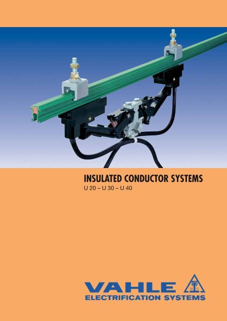
<strong>INSULATED</strong> <strong>CONDUCTOR</strong> <strong>SYSTEMS</strong><br />
U 20 – U 30 – U 40
2<br />
<strong>INSULATED</strong> <strong>CONDUCTOR</strong>S U 20 – U 30 – U 40<br />
INDEX U 20 U 30 U 40<br />
Page Page Page<br />
Basic description 4 4 4<br />
Conductors 5 20 30<br />
Rigid joints 5 21 32<br />
Expansion sections 6 21 32<br />
Locating clamps 8 22 32<br />
End caps 8 22 32<br />
Feed terminals 6 22 33<br />
Contact paste 6 22 32<br />
Transfer guides 7 23 34<br />
Transfer funnels 7 25 -<br />
Sectionalizing 7 23 34<br />
Hangers 9 24 35<br />
Insulators 8 24 35<br />
Rail holders 8 24 35<br />
Compact hangers/Attachment hardware/Bracket profiles 9 25 –<br />
Collectors 10-12 26 36<br />
Components and spares for collectors 13-18 27-29 37<br />
Examples for ordering 19 27 38<br />
Grounding device 39 39 39<br />
Questionnaire 40 40 40<br />
Typical installations 41 41 41
<strong>INSULATED</strong> <strong>CONDUCTOR</strong>S U 20 – U 30 – U 40<br />
BASIC DESCRIPTION<br />
Seite 4<br />
U 20<br />
For cranes, self-propelled monorail carriers, amusement rides<br />
– for installations with curves, switches, turntables, special<br />
control conductor systems for pickling lines and galvanizing plants<br />
Pages 5–19<br />
U 30<br />
For bridge and portal crane electrification, heavy monorail<br />
systems, amusement rides, construction and maintenance<br />
hoists and for high voltage applications up to 10 kV<br />
Pages 20 – 29<br />
U 40<br />
For heavy cranes and loading bridges, container and transtainer<br />
systems, coking machinery, for dockside trench type electrification<br />
systems in ports, shipyards and steel mills – for all heavy duty and<br />
for high voltage applications up to 10 kV<br />
Pages 30 – 38<br />
GROUNDING DEVICE<br />
Page 39<br />
QUESTIONNAIRE<br />
Pages 40<br />
TYPICAL INSTALLATIONS<br />
Seite 41<br />
3
4<br />
<strong>INSULATED</strong> <strong>CONDUCTOR</strong>S U 20 – U 30 – U 40<br />
General<br />
VAHLE insulated conductors are designed in accordance to international<br />
safety regulations for a multitude of power supply applications.<br />
They fully meet VDE 0100 and are finger safe to EN<br />
60529 (VDE 0470, part 1, protection code IP 23). They are<br />
UL, SAA and SEV approved.<br />
For current collectors touch protection is only given if carbon<br />
brushes are fully entered into the conductors. Conductor installations<br />
in the reach of hand, where collectors leave<br />
the conductor rails during normal operation,<br />
must be protected against accidental touch by the<br />
customer e.g. switch-off or separation. This refers<br />
to voltages above 25 VAC resp. 60 VDC, only.<br />
The adjacent picture demonstrates that the VDE test<br />
finger cannot reach live conductors – finger safety is<br />
guaranteed.<br />
For high voltage applications we do recommend<br />
our adequate high voltage insulators but applicable<br />
international or local safety requirements have<br />
to be considered.<br />
The shrouding which envelops the various conductors<br />
is an excellent insulator. There-fore our unipole insulated<br />
conductors guarantee utmost safety in operation.<br />
The ground conductor is identified by international colour coding.<br />
For obvious safety reasons phase and ground collectors are not interchangeable.<br />
Any number of conductors can be accomplished by installing various<br />
powerails side by side.<br />
Standard rail sections are 6 m long, shorter lengths to coincide with<br />
your runway requirements are available.<br />
Approvals<br />
U 20 and U 30: UL-approval<br />
Please ask in case of order<br />
Hangers<br />
Support brackets will be prepared in accordance to your local<br />
requirements or provided by others considering your runway<br />
system configuration.<br />
U 20: see page 5 - U 30: see page 20 - U40: see page 30.<br />
Insulators<br />
The insulated conductor rails could be installed with insulators.<br />
Through this is the creepage distance longer. In systems with difficult<br />
ambient and environmental conditions (high humidity, electroplating<br />
shop, chemical industry etc.) are this insulators required.<br />
Insulating covers<br />
Electrical properties:<br />
dielectric strength<br />
DIN 53 481<br />
specific resistance<br />
DIN 53 482<br />
Surface resistance according<br />
to IEC 60093<br />
Creep resistance according<br />
to IEC 60112/ VDE 0303<br />
Mechanical properties:<br />
flexible strength<br />
tensile strength<br />
Temperature resistance<br />
flame test proof<br />
per DIN 4102<br />
part 1<br />
Standard<br />
shrouding<br />
colour green<br />
30-40<br />
kV/mm<br />
5 x 10¹⁵ Ohm/cm<br />
1013 Ohm<br />
CTI> 600-2,7<br />
75 N/mm 2<br />
± 10%<br />
High temp.<br />
shrouding<br />
colour grey<br />
45<br />
kV/mm<br />
5 x 10¹⁷ Ohm/cm<br />
1015 Ohm<br />
CTI> 600-2,7<br />
95 N/mm 2<br />
± 10%<br />
50 N/mm 2<br />
± 10%<br />
50 N/mm 2<br />
± 10%<br />
–30 °C thru<br />
+55 °C<br />
class B1<br />
no flaming particles,<br />
self extinguishing<br />
–30 °C thru<br />
+85 °C<br />
Joints<br />
The connection between the conductor rails is made through<br />
bolted joints.<br />
For touch protection every joint will be covered through a joint cap.<br />
With bigger temperature fluctuation and length above 100 m are<br />
expansion sections required (see installation instructions).<br />
Feed terminals<br />
The feed will be installed between two conductor rails instead of<br />
a standard joint. To connect this feed please consider single<br />
core cables.<br />
End caps<br />
The end caps are the touch proof end of the conductor rails.<br />
Entry funnel and transfer guides<br />
For the use in spurlines, turntables and switches are transfer guides<br />
and entry funnels available.<br />
Isolating sections<br />
Isolating sections are electrical interrupts of the conductor. Under<br />
normal operating conditions a cross over with collectors to switch<br />
the voltage off or on is only allowed with low power ratings<br />
(control current).<br />
For control reasons, feed tracks, repair areas etc. we supply<br />
isolating sections.<br />
Curves<br />
The insulated conductor rails could be bend in horizontal or<br />
vertical curves. The rails are depending on type and radius bend<br />
in our factory or on site.<br />
Current collectors<br />
Depend on usage single or double collectors are used.<br />
The mentioned contiuous currents are for collectors in standard<br />
use with conudoctor profiles with copper surface. With the<br />
AE-conductor rail the collectors of consumers which remain at<br />
one place continously or work under a very low travel speed<br />
(e.g. 10/min.) the maximum continous current is approx. 50% of<br />
the mentioned continous current.<br />
The length of the cable should not extend 3 m if the fuse is not<br />
laid out for this load capacity. (See aswell DIN VDE 0100,<br />
part 430 and DIN EN 60204)<br />
Note: The a.m. Often occurs in systems with more than one<br />
collector)<br />
The supplied connecting cables (H07RN-F) are for the mentioned<br />
nominal currents big enough. For the different cable layouts<br />
have the reduction factors of DIN VDE 0298 to be considered.<br />
Safety advice<br />
It must be ensured that the arrangement of the conductor system<br />
provides minimum distances (0,5 m) between fixed and mobile<br />
parts. (i.e. Between conductor rails, collector trolleys and towing<br />
arms) so as to avoid the risk of pinching.<br />
Chemical resistance for both designs:<br />
Shroudings in the standard design (color green) and in the heat<br />
resistant design (color grey) are resistance against mineral oil,<br />
fats, caustic soda 25%, caustic soda 50%, concentrated hydrochloric<br />
acid; suflfuric acid upto 50%.<br />
Please note: For use in galvanizing and pickling plants,<br />
under agressive conditions and low voltage applications<br />
we would appreciate receiving detailled information,especially<br />
of the environmental conditions.<br />
For quotations and order processing including Powerail<br />
systems with curves, dead sections, turntables, switches<br />
etc. we require your drawings or sketches.
Type<br />
Weight kg/m<br />
Standard shroud, color green<br />
Order- No. phase (2)<br />
Order- No. ground (2)<br />
Order- No. phase (2)<br />
Order- No. ground (2)<br />
U 20/50 CE<br />
0,500<br />
12701 •<br />
12711 •<br />
High temperature shrouding, color gray<br />
Engineering data<br />
Type<br />
U 20/50 CE<br />
U 20/50 AC<br />
U 20/50 C<br />
U 20/50 CH<br />
Rigid joints<br />
12706 •<br />
12716 •<br />
Conductor cross section<br />
mm 2<br />
Cu Al<br />
stainless<br />
steel<br />
<strong>INSULATED</strong> <strong>CONDUCTOR</strong>S U 20<br />
Leakage<br />
distance<br />
of shroud<br />
mm<br />
U 20/50 AC<br />
0,400<br />
12702 •<br />
12712 •<br />
12707 •<br />
12717 •<br />
Max.<br />
Voltage (5)<br />
V<br />
U 20/50 C<br />
0,580<br />
12703 •<br />
12713 •<br />
12708 •<br />
12718 •<br />
max. continuous<br />
ampere<br />
capacity<br />
A by 35 °C<br />
Resistance (4)<br />
Ohm/1000 m<br />
Type for conductor Weight kg<br />
UV 20/50<br />
UV 20/50 K 4 (1)<br />
30<br />
18<br />
50<br />
50<br />
20<br />
radius<br />
horizontal curve R H<br />
30<br />
18 45<br />
45<br />
45<br />
45<br />
Conductor code<br />
U = Unipole insulated conductor<br />
20 = Shrou size<br />
50 = Cross sectional area (mm2 )<br />
CE = Copper/stainless steel conductor<br />
AC = Aluminium/copper conductor<br />
C = Copper conductor<br />
CH = Copper conductor with extra deep groove for high<br />
speed application and lateral mounting<br />
Conductor distance:<br />
With insulated hangers: 50 mm<br />
With compact hangers 23-26 mm<br />
Chemical and electrical values aswell as temperature<br />
range see page 4<br />
16<br />
62<br />
18<br />
10<br />
6<br />
10<br />
1000<br />
1000<br />
1000<br />
1000<br />
80<br />
120<br />
210<br />
210<br />
U 20/50 AC U 20/50 C U 20/50 CH U 20/50 CE<br />
U 20/50 AC U 20/50 CE U 20/50 CH U 20/50 CE<br />
0,140<br />
0,140<br />
0,587<br />
0,483<br />
0,376<br />
0,376<br />
Supply lengths:<br />
6 m standard;<br />
shorter lengths are available<br />
Support spacing:<br />
– for straight runs and lateral curves: 1000 mm<br />
– for horizontal curves RH < 5 m (3) : 500 mm<br />
– for horizontal curves RH > 5 m: 1000 mm<br />
Bending:<br />
Factory fabricated min. R = 400 mm<br />
Field fabrication min. R = 4000 mm<br />
(1) Stainless steel hardware<br />
(2) The last number of the order-no. Is the single length in meter. Please add 1,2 … 6 in the end. Short length have to be rounded up.<br />
(3) Recommended<br />
(4) With frequency of 50 Hz and 20 °C.<br />
(5) Not with UL-approval; U UL = 600 V<br />
19,5<br />
10<br />
24<br />
11<br />
100<br />
U 20/50 CH<br />
0,560<br />
12704 •<br />
12714 •<br />
12709 •<br />
12719 •<br />
12<br />
Impedanz (4)<br />
Ohm/1000 m<br />
0,612<br />
0,600<br />
0,416<br />
0,416<br />
Order- No.<br />
120 180<br />
126 504<br />
40<br />
5
ACCESSORIES FOR U 20<br />
Expansion sections<br />
Factory assembeld on 1 m long conductor section incl. one joint splice.<br />
They are used i systems >100 m. The 1 m expansion assembly is part of<br />
the system length and has to be considered.<br />
Type Weight kg<br />
UDV 20/50 CE K 4 (1)<br />
UDV 20/50 AC K 4 (1)<br />
UDV 20/50 C K 4 (1)<br />
UDV 20/50 CH K 4 (1)<br />
Feed terminals<br />
To be used instead of rigid joints<br />
Feed cable: 2 of max. 50 mm 2<br />
6 (1) Stainless steel hardware<br />
338 325<br />
43<br />
Order- No.<br />
phase ground<br />
1000 +17<br />
at 20 °C<br />
-13<br />
to Δ t max. L / U 20 to Δ t max. L / U 20<br />
Ermittlung der Dehnungsteilstücke<br />
n = Number of UDV (rounded)<br />
20 °C 88 m 40 °C 44 m<br />
n = L1 L<br />
L1 = Length of assembly minus 100 m<br />
L = Expansion capacity max. of UDV (see table)<br />
30 °C 58 m 50 °C 35 m<br />
Standard shrouding, color green Hihg temperature shrouding, color grey<br />
Type<br />
UE 20/50 K4 (1)<br />
UE 20/50 K 4 (1)- M<br />
Type<br />
UEN 20/50 K4 (1) -A<br />
UEN 20/50 K4 (1) -A-M<br />
UEN 20/50 K4 (1) -B<br />
UEN 20/50 K4 (1) -B-M<br />
Cannot be used as a rigid joint.<br />
Feed cable: 1 of max. 6 mm 2<br />
Type<br />
Cannot be used as a rigid joint.<br />
Feed cable: 1 of max. 4 mm 2<br />
0,622<br />
0,622<br />
1,030<br />
1,020<br />
Weight kg Order- No.<br />
0,290<br />
0,290<br />
126 522<br />
121 459<br />
Weight kg Order- No.<br />
UES 20/50 K 4 (1) 0,060 126 530<br />
Contact Paste for joints and feeds<br />
126 514<br />
126 516<br />
126 518<br />
126 520<br />
Weight kg Order- No.<br />
0,120<br />
0,120<br />
0,120<br />
0,120<br />
126 515<br />
126 517<br />
126 519<br />
126 521<br />
126 526<br />
121 061<br />
120 116<br />
121 165<br />
58,5<br />
19,5<br />
19,5<br />
19,5<br />
23<br />
21,5<br />
Max. expansion = 30 mm<br />
Type Weight kg<br />
UDV 20/50 CE K 4 (1)<br />
UDV 20/50 AC K 4 (1)<br />
UDV 20/50 C K 4 (1)<br />
UDV 20/50 CH K 4 (1)<br />
23<br />
23<br />
23<br />
29<br />
100<br />
100<br />
100<br />
140<br />
Typ UE<br />
40<br />
Typ UEN-A<br />
40<br />
Typ UEN-B<br />
Typ UES<br />
0,622<br />
0,622<br />
1,030<br />
1,020<br />
40<br />
80<br />
Order- No.<br />
phase ground<br />
126 674<br />
126 676<br />
126 678<br />
126 680<br />
shown without cap<br />
M 6 x 8<br />
M 6 x 8<br />
16 62<br />
126 675<br />
126 677<br />
126 679<br />
126 681<br />
100 ml for approx. 200 joints Order- No. 121 502<br />
14<br />
30<br />
62<br />
62<br />
16<br />
16<br />
M 5 x 12<br />
M 10 x 25
Transfer funnels<br />
Transfer funnels are for spurlines, switches and turntables required.<br />
With insulated hangers the type EM 20 in 1-6 pole design is used.<br />
For the layout of conductor rails in compact hangers is the type<br />
EMK 20 in 1-7 pole design available.<br />
The conductor distance with insulated hangers is min. 40 mm and<br />
with compact arrangement 23-26 mm.<br />
To prepare a quote please mention rail type, number of poles and<br />
poisition of PE.<br />
Transfer guides<br />
These guides serve for transfer or power interrupting-applications.<br />
Max. horizontal and vertical offset: ± 2 mm; gap between two<br />
transfer guides max. 8 mm.<br />
Extra hangers are required and to be ordered separately.<br />
Type<br />
US 20/50 CH K 4 (1)<br />
US 20/50 C K 4 (1)<br />
US 20/50 A K 4 (1)<br />
Type for conductor Weight kg Order- No.<br />
IT/U 20/50 CH-M<br />
IT/U 20/50 C-M<br />
IT/U 20/50 A-M<br />
(1) Stainless steel hardware<br />
for conductor Weight kg Order- No.<br />
U 20/50 CH<br />
U 20/50 C<br />
U 20/50 AC<br />
U 20/50 CE<br />
Transfer guides US 20 are fastened to conductor ends by means<br />
of one nylon screw.<br />
U 20/50 CH<br />
U 20/50 C<br />
U 20/50 AC<br />
U 20/50 CE<br />
0,046<br />
0,046<br />
0,046<br />
0,005<br />
0,005<br />
0,005<br />
120 849<br />
120 848<br />
120 847<br />
Isolating sections<br />
Type M: Factory assembled per system layout<br />
Type L: Loose, incl. 2 locking pins 3 x 10<br />
On both sides a hanger has to be considered.<br />
Use one extra hanger each side, max. 200 mm away for<br />
stability.<br />
Collectors, hangers and feeds have to be ordered seperatly.<br />
max.200<br />
120 950<br />
120 940<br />
126 536<br />
ACCESSORIES FOR U 20<br />
Picture shows Typ EM 20<br />
To avoid voltage by-pass by carbon brushes and to separate maintenance bays, control and main feed sections, double isolating sections<br />
are recommended.<br />
Dim. A depends on type and number of current collectors and stopping distance of the crane.<br />
Type for conductor Weight kg Order- No.<br />
IT/U 20/50 CH-L<br />
IT/U 20/50 C-L<br />
IT/U 20/50 A-L<br />
23<br />
w/o cond.<br />
100 A<br />
100<br />
max.200<br />
min.160<br />
feed terminal<br />
60<br />
15<br />
100<br />
w/o cond.<br />
max.200 max.200<br />
U 20/50 CH<br />
U 20/50 C<br />
U 20/50 AC<br />
U 20/50 CE<br />
2<br />
4<br />
0,005<br />
0,005<br />
0,005<br />
1<br />
3<br />
120 010<br />
120 009<br />
120 008<br />
7
Locating clamp<br />
14<br />
ACCESSORIES FOR U 20<br />
Type Weight kg<br />
USK 20 K 4 (1) 0,028<br />
Insulator (2)<br />
GH 40-M 6<br />
GH 40-M 6 K 4 (1)<br />
Supplied with bolt M 6 x 12<br />
Type Weight kg<br />
UAK 20<br />
UAK 20 K 4 (1)<br />
End caps incl. Locking pin<br />
22<br />
Type Weight kg<br />
UK 20-L<br />
UK 20-M<br />
Fixpoint (insulated rail holder with<br />
2 locating clamps)<br />
0,075<br />
0,075<br />
0,010<br />
0,010<br />
0,010<br />
0,010<br />
25<br />
8 (1) Stainless steel hardware<br />
(2) For installation in slotted holes use on both sides discs according to DIN 9021.<br />
(3) For aggressive mediums<br />
22<br />
25<br />
Order- No.<br />
120 140<br />
121 060<br />
126 544<br />
Order- No.<br />
126 546<br />
126 548<br />
Order- No.<br />
120 120<br />
120 987<br />
M 6<br />
Insulated hangers (2)<br />
Type Weight kg<br />
UAM 20<br />
UAM 20 K 4 (1)<br />
Type Weight kg<br />
UAS 20 K 4 (1)<br />
UAS 20 K 4 (1)- H (3)<br />
0,025<br />
0,025<br />
Insulator (2) for aggressive mediums<br />
Cantilever strength = 3000 N<br />
Leakage distance = 60 mm cantilever strength = 1000 N<br />
Type Weight kg<br />
Order- No.<br />
Leakage distance = 62 mm<br />
Rail holder for insulators<br />
for conductor rails U20/50 CH, 20/50 C, U20/50 AC and U20/50 CE<br />
20<br />
7<br />
A<br />
M6<br />
24<br />
28<br />
Type A<br />
U20/50 CH 20<br />
U20/50 C 21<br />
U20/50 AC<br />
U20/50 CE<br />
22<br />
Type A<br />
U20/50 CH 33<br />
U20/50 C 34<br />
U20/50 AC<br />
U20/50 CE<br />
35<br />
Type Weight kg<br />
UIK 42-M 6 K 4 (1) 0,110<br />
Supplied with bolt M 6 x 10 and spring washer<br />
0,014<br />
0,014<br />
Type Weight kg<br />
SE 8<br />
SE 8 K 4 (1)<br />
20<br />
0,055<br />
0,055<br />
Order- No.<br />
126 540<br />
126 542<br />
Order- No.<br />
120 883<br />
Order- No.<br />
126 550<br />
120 755<br />
Securing element for compact hangers KH 20/5....<br />
20<br />
max.9<br />
A<br />
M 8<br />
Ø 45<br />
M 6<br />
M 6 x 8,5 deep<br />
for conductor rails U 20/50 CH, 20/50 C, U 20/50 AC and U 20/50 CE<br />
max. 3<br />
7,4<br />
A<br />
M6<br />
21<br />
25x30<br />
M8<br />
Ø28<br />
24<br />
24<br />
max. 10<br />
42 4 20<br />
Order- No.<br />
170 677<br />
170 955<br />
3,5<br />
Type A<br />
U20/50 CH 17<br />
U20/50 C 18<br />
U20/50 AC<br />
U20/50 CE<br />
19
BE 6<br />
BE 6 K 4 (1)<br />
0,015<br />
0,015<br />
120 406<br />
120 778<br />
ACCESSORIES FOR U 20<br />
Any number of conductors poles can be assembled with compact hangers.<br />
Can only be used with collectors of type KST. The joints and feeds have to be arrangend staggered.<br />
Compact hangers, 5 poles to be bolted (2)<br />
Type A<br />
U20/50 CH 41<br />
U20/50 C 42<br />
U20/50 AC<br />
U20/50 CE<br />
43<br />
Type Weight kg<br />
KA 20/5 0,041<br />
Type B Weight kg<br />
KH 20/5-1<br />
KH 20/5-2<br />
KH 20/5-3<br />
KH 20/5-4<br />
KH 20/5-5<br />
0,008<br />
0,018<br />
0,028<br />
0,038<br />
0,048<br />
Order- No.<br />
120 933<br />
120 934<br />
126 614<br />
126 615<br />
126 616<br />
Order- No.<br />
126 613<br />
Compact hangers for bracket profiles 38/17 G<br />
Typ A<br />
U20/50 CH 23<br />
U20/50 C 24<br />
U20/50 AC<br />
U20/50 CE<br />
25<br />
Attachment hardware for compact hangers, insulated hangers and insulators<br />
Type Weight kg Order- No.<br />
Bracket profiles 38/17<br />
incl. locking hardware<br />
Type<br />
HU 20/230<br />
HU 20/360<br />
HU 20/490<br />
24<br />
50<br />
76<br />
102<br />
128<br />
for 1 KA 20/5 are 2 pcs. BE 6 required.<br />
Length<br />
mm<br />
230<br />
360<br />
490<br />
max.<br />
poles<br />
5<br />
10<br />
15<br />
Longer Bracket profiles on request.<br />
M6 x 10 deep<br />
Weight<br />
kg<br />
0,520<br />
0,750<br />
0,970<br />
Order- No.<br />
120 833<br />
120 834<br />
120 835<br />
(1) Stainless steel hardware .<br />
(2) For installation in slotted holes use on both sided discs according to DIN 9021.<br />
A<br />
3<br />
SW 6<br />
25<br />
A 17<br />
38<br />
18<br />
25<br />
117<br />
75<br />
12,5 23 23 23 23 12,5<br />
128<br />
12 26 26 26 26 12<br />
17<br />
28 B 30<br />
M 6<br />
M 8<br />
Klemmbereich<br />
max. 13<br />
screw M 8<br />
9
CURRENT COLLECTORS FOR U 20<br />
Current collectors Double collectors<br />
with 2 m connecting cable<br />
lift and swivel ± 20 mm<br />
contact pressure: approx. 9 N<br />
Type (1)<br />
KST 15<br />
KST 40<br />
KST 60<br />
Ampacity<br />
A<br />
15<br />
40<br />
60<br />
mm2 Connecting cable<br />
ø max/<br />
mm<br />
2,5<br />
6,0<br />
10,0<br />
4,4<br />
11,0<br />
12,5<br />
Weight<br />
kg<br />
0,256<br />
0,428<br />
0,588<br />
phase<br />
black<br />
150 891<br />
152 840<br />
153 675<br />
Order- No.<br />
ground<br />
yellow<br />
150 892<br />
152 850<br />
153 676<br />
Current collectors Double collectors<br />
with 2 m connecting cable<br />
lift and swivel ± 40 mm<br />
contact pressure: approx. 9 N<br />
Type (1)<br />
KSTL 15<br />
KSTL 40<br />
KSTL 60<br />
Ampacity<br />
A mm 2<br />
15<br />
40<br />
60<br />
Connecting cable<br />
2,5<br />
6,0<br />
10,0<br />
ø max/<br />
mm<br />
4,4<br />
11,0<br />
12,5<br />
Weight<br />
kg<br />
0,272<br />
0,453<br />
0,591<br />
phase<br />
black<br />
150 893<br />
152 860<br />
153 677<br />
Order- No.<br />
ground<br />
yellow<br />
150 894<br />
152 870<br />
153 678<br />
Current collectors for transfer funnels EMK 20 (1) Double collectors for transfer funnels EMK 20 (1)<br />
ca. 135<br />
spring released hight<br />
Type (1)<br />
100<br />
75<br />
100<br />
75<br />
KSTLU 15<br />
KSTLU 40<br />
KSTLU 60<br />
100<br />
75<br />
Ampacity<br />
A<br />
15<br />
40<br />
60<br />
152<br />
100<br />
152<br />
with 2 m connecting cable<br />
lift ± 20 mm<br />
swivel ± 40 mm<br />
contact pressure: approx. 9 N<br />
mm2 Connecting cable<br />
ø max/<br />
mm<br />
2,5<br />
6,0<br />
10,0<br />
4,4<br />
11,0<br />
12,5<br />
Weight<br />
kg<br />
0,313<br />
0,499<br />
0,652<br />
phase<br />
black<br />
150 895<br />
153 791<br />
153 793<br />
Order- No.<br />
ground<br />
yellow<br />
150 896<br />
153 792<br />
153 794<br />
Type (1)<br />
KDST 30<br />
KDST 80<br />
KDST 120<br />
Type (1)<br />
10 (1) Suffix types e.g. KST 15 KST 15 PH Order- No. 150 891<br />
(2) Collectors locate in unstressed condition automatic to phase center.<br />
Ampacity while using stainless steel conductors on request.<br />
12<br />
12<br />
65<br />
18<br />
85<br />
18<br />
12<br />
85<br />
ca. 50<br />
17<br />
4<br />
17<br />
4<br />
17<br />
4<br />
with 2 x 2 m connecting cable<br />
lift and swivel ± 20 mm<br />
contact pressure:approx. 9 N per Brush<br />
KDSTL 30<br />
KDSTL 80<br />
KDSTL 120<br />
Type (1)<br />
Ampacity<br />
A<br />
30<br />
80<br />
120<br />
Ampacity<br />
A<br />
30<br />
80<br />
120<br />
mm2 Connecting cable<br />
ø max/<br />
mm<br />
2,5<br />
6,0<br />
10,0<br />
A/<br />
mm2 2,5<br />
6,0<br />
10,0<br />
4,4<br />
11,0<br />
12,5<br />
Connecting cable<br />
d max/<br />
mm<br />
4,4<br />
11,0<br />
12,5<br />
Weight<br />
kg<br />
0,471<br />
0,821<br />
1,114<br />
with 2 x 2 m connecting cable<br />
lift and swivel ± 40 mm<br />
contact pressure: approx. 9 N per brush<br />
100<br />
75<br />
100<br />
75<br />
100<br />
75<br />
KDSTLU 30<br />
KDSTLU 80<br />
KDSTLU 120<br />
Ampacity<br />
A<br />
30<br />
80<br />
120<br />
mm2 Connecting cable<br />
ø max/<br />
mm<br />
2,5<br />
6,0<br />
10,0<br />
200<br />
304<br />
4,4<br />
11,0<br />
12,5<br />
304<br />
Weight<br />
kg<br />
0,492<br />
0,822<br />
1,188<br />
with 2 x 2 m connecting cable<br />
lift ± 20 mm<br />
swivel ± 40 mm<br />
contact pressure: approx. 9 N per brush<br />
12<br />
12<br />
12<br />
Weight<br />
kg<br />
0,541<br />
0,895<br />
1,231<br />
phase<br />
black<br />
150 897<br />
152 960<br />
153 679<br />
phase<br />
black<br />
150 899<br />
152 980<br />
153 681<br />
phase<br />
black<br />
150 902<br />
153 786<br />
153 795<br />
65<br />
18<br />
ground<br />
Order- No.<br />
ground<br />
Order- No.<br />
ground<br />
Order- No.<br />
12<br />
ground<br />
yellow<br />
150 898<br />
152 970<br />
153 680<br />
12<br />
85<br />
18<br />
ground<br />
yellow<br />
150 901<br />
152 990<br />
153 682<br />
85<br />
ca. 50<br />
ca. 135<br />
spring released hight<br />
12<br />
ground<br />
yellow<br />
150 903<br />
153 787<br />
153 796
18<br />
Current collectors<br />
(1) Collectors UST -UDST and USTU – UDSTU only for 35 mm phase distance.<br />
Ampacity while using stainless steel conductors on request.<br />
CURRENT COLLECTORS FOR U 20<br />
Current collectors (1) Double collectors (1)<br />
100<br />
Type<br />
Current collectors for transfer funnels EM (1) Double collector for transfer funnels EM (1)<br />
Type<br />
with 2 m connecting cable<br />
contact pressure: approx. 5 N<br />
with 2 m connecting cable<br />
lift ± 25 mm<br />
swivel ± 25 mm<br />
contact pressure: approx. 10 N<br />
UST 40<br />
UST 60<br />
ca. 135<br />
spring released hight<br />
with 2 m connecting cable<br />
lift ± 25 mm<br />
swivel ± 25 mm<br />
contact pressure: approx. 10 N<br />
USTU 40<br />
USTU 60<br />
Ampacity<br />
A<br />
40<br />
60<br />
Ampacity<br />
A<br />
40<br />
60<br />
mm2 Connecting-Cable<br />
ø max/<br />
mm<br />
6<br />
10<br />
mm2 Connecting-Cable<br />
ø max/<br />
mm<br />
6<br />
10<br />
11,0<br />
12,5<br />
11,0<br />
12,5<br />
Weight<br />
kg<br />
0,605<br />
0,875<br />
Dimension in parenthesis for UST 60<br />
18<br />
85<br />
60<br />
90<br />
(120)<br />
100<br />
90<br />
(120)<br />
140 (190)<br />
146<br />
146<br />
85 (95)<br />
Weight<br />
kg<br />
0,635<br />
0,815<br />
Dimension in parenthesis for USTU 60<br />
12<br />
16<br />
16<br />
13,5<br />
4,4<br />
ground<br />
phase<br />
black<br />
120 961<br />
120 963<br />
phase<br />
black<br />
120 969<br />
120 971<br />
34<br />
4<br />
Order- No.<br />
Order- No.<br />
ground<br />
yellow<br />
120 962<br />
120 964<br />
34<br />
4<br />
12<br />
ground<br />
yellow<br />
120 970<br />
120 972<br />
Type<br />
KST 30<br />
KST 55<br />
KSTL 30<br />
KSTL 55<br />
Type<br />
UDST 80<br />
UDST 120<br />
Type<br />
UDSTU 80<br />
UDSTU 120<br />
Ampacity<br />
A<br />
30<br />
55<br />
30<br />
55<br />
Ampacity<br />
A<br />
80<br />
120<br />
Ampacity<br />
A<br />
80<br />
120<br />
mm2 Connecting-Cable<br />
ø max/<br />
mm<br />
2,5<br />
6,0<br />
2,5<br />
6,0<br />
mm2 Connecting-Cable<br />
ø max/<br />
mm<br />
6<br />
10<br />
5<br />
11<br />
5<br />
11<br />
mm2 Connecting-Cable<br />
ø max/<br />
mm<br />
6<br />
10<br />
11,0<br />
12,5<br />
11,0<br />
12,5<br />
lift & swivel<br />
mm<br />
± 20<br />
± 20<br />
± 30<br />
± 30<br />
Dimensions in parenthesis for KSTL<br />
90<br />
(120)<br />
292<br />
Weight<br />
kg<br />
1,100<br />
1,600<br />
Weight<br />
kg<br />
1,160<br />
1,550<br />
Weight<br />
kg<br />
0,240<br />
0,368<br />
0,240<br />
0,368<br />
Dimension in parenthesis for UDST 120<br />
Dimension in parenthesis for UDSTU 120<br />
phase<br />
black<br />
152 085<br />
154 438<br />
152 089<br />
154 443<br />
phase<br />
black<br />
120 965<br />
120 967<br />
phase<br />
black<br />
120 973<br />
120 975<br />
Order- No.<br />
with 2 x 2 m connecting cable<br />
lift ± 25 mm<br />
swivel ± 25 mm<br />
contact pressure: approx. 10 N per brush ground<br />
90<br />
(120)<br />
292<br />
with 2 x 2 m Connecting cable<br />
lift ± 25 mm<br />
swivel ± 25 mm<br />
contact pressure: approx. 10 N per Brush<br />
16<br />
16<br />
Order- No.<br />
ground<br />
Order- No.<br />
ground<br />
yellow<br />
152 086<br />
154 439<br />
152 091<br />
154 444<br />
100<br />
18<br />
16<br />
ground<br />
yellow<br />
120 966<br />
120 968<br />
100<br />
8<br />
ca. 135<br />
spring released hight<br />
50 24<br />
ground<br />
yellow<br />
120 974<br />
120 976<br />
11
12<br />
CURRENT COLLECTORS FOR U 20<br />
Use in aggressive mediums like pickling plants, galvanizing plants and galvanic systems.<br />
Current collectors phase (1) Double collectors phase (1)<br />
ca. 140<br />
spring released hight<br />
with 2 m connecting cable<br />
lift +30 mm / -40 mm<br />
swivel ± 35 mm<br />
contact pressure: approx. 9 N<br />
Type (1)<br />
KSTL 35 VB PH<br />
KDSTL 70 VB PH<br />
Ampacity<br />
A mm2 Connecting cable<br />
ø max/<br />
mm<br />
35<br />
70<br />
6,0<br />
6,0<br />
with 2 m connecting cable<br />
lift +30 mm / -40 mm<br />
swivel ± 35 mm<br />
contact pressure: approx. 9 N per brush<br />
11,0<br />
11,0<br />
Weight<br />
kg<br />
0,410<br />
0,750<br />
Order- No.<br />
phase<br />
black<br />
121 186<br />
121 188<br />
Current collectors, ground (2) Double collectors, ground (2)<br />
ca. 140<br />
spring released hight<br />
110<br />
86<br />
110<br />
86<br />
152<br />
152<br />
with 2 m connecting cable<br />
lift +30 mm / -40 mm<br />
swivel ± 35 mm<br />
contact pressure: approx. 9 N<br />
Type (1)<br />
85<br />
KSTL 35 V PE<br />
KDSTL 70 V PE<br />
(1) Phase with touch protection<br />
(2) PE without touch protection<br />
18<br />
85<br />
18<br />
16<br />
4<br />
16<br />
4<br />
Ampacity<br />
A mm2 Connecting cable<br />
ø max/<br />
mm<br />
35<br />
70<br />
6,0<br />
6,0<br />
110<br />
110<br />
with 2 m connecting cable<br />
lift +30 mm / -40 mm<br />
swivel ± 35 mm<br />
contact pressure: approx. 9 N per brush<br />
6,0<br />
6,0<br />
Weight<br />
kg<br />
0,328<br />
0,554<br />
304<br />
304<br />
Order- No.<br />
phase<br />
black<br />
121 187<br />
121 189<br />
12<br />
12<br />
85<br />
18<br />
85<br />
18<br />
ground<br />
ca. 140<br />
spring released hight<br />
ca. 140<br />
spring released hight<br />
12
Collector bracket for KST and UST<br />
Prepard for<br />
ground collector<br />
Collector brackets<br />
for current collectors for current collectors for control collectors<br />
KST / KDST see page 10 KST see page 10 KST / KDST<br />
18<br />
Type Weight kg Order- No.<br />
UMAS 12 HS-A 200<br />
Tension springs<br />
Type<br />
ZF 3<br />
ZF 4<br />
ZF 5<br />
15<br />
37,5<br />
12<br />
(18)<br />
30<br />
65<br />
slotted hole 11 x 30<br />
0,740<br />
KST 15 thru KDST 120<br />
ACCESSORIES FOR CURRENT COLLECTORS U 20<br />
121 092<br />
Type Weight kg Order- No.<br />
UMAS 12 HS-B 200<br />
Suitable for phase distance of max. 55 mm (3 pole + ground).<br />
Type<br />
UM 12 (for KST)<br />
UM 12 K4 (1) (for KST..V)<br />
UM 16 (for UST)<br />
0,740<br />
121 093<br />
for current collectors Weight kg<br />
KSTL 15 thru KDSTL 120<br />
and KSTLU 15 thru KDSTLU 120<br />
UST 40, USTU 40, UDST 80, UDSTU 80<br />
UST 60, USTU 60, UDST 120, UDSTU 120<br />
Weight kg<br />
0,675<br />
0,688<br />
1,175<br />
Order- No.<br />
153 506<br />
121 162<br />
126 574<br />
With a length above 600 mm for the towing arm a support have<br />
to be considered on site to prevent bending or twisting.<br />
Longer length are available.<br />
0,003<br />
0,004<br />
0,007<br />
Type Weight kg Order- No.<br />
UMAS 12 ST 200<br />
S<br />
mm<br />
1,2<br />
1,3<br />
1,5<br />
D<br />
mm<br />
10,8<br />
11,0<br />
13,8<br />
L<br />
mm<br />
28,5<br />
29,0<br />
40,0<br />
0,740<br />
121 094<br />
Order- No.<br />
153 516<br />
153 517<br />
ZF 4H 0,004 1,3 11,0 29,0 170 601<br />
KSTL 35 thru KDSTL 70<br />
(1) Stainless steel hardware .<br />
600<br />
Clamp dimension for UM12<br />
59<br />
90<br />
230<br />
59<br />
40 mm wide<br />
S<br />
L<br />
(12)<br />
16<br />
D<br />
126 585<br />
13
Copper-graphite brushes<br />
RH<br />
Dim H: max. wear for U 20/50 C<br />
Type<br />
KMK 60<br />
KMK 60 U<br />
Cable attachment clamp<br />
for current collectors Type KSTLU, KDSTLU<br />
14<br />
COLLECTOR COMPONENTS U 20<br />
100<br />
75<br />
for current collectors Weight kg<br />
RH mm Order- No.<br />
KST 15, KST 40, KDST 30, KDST 80, KSTL 15, KSTL 40, KDSTL 30,<br />
KDSTL 80, KST 60, KDST 120, KSTL 60, KDSTL 120 3 0,110 153 512<br />
KSTLU 15, KSTLU 40, KSTLU 60,<br />
KDSTLU 30, KDSTLU 80, KDSTLU 120<br />
3 0,115 153 513<br />
KMU 40 UST 40, UDST 80 12 0,060 126 579<br />
KMU 40 U USTU 40, UDSTU 80 12 0,050 126 696<br />
KMU 60 UST 60, UDST 120 18 0,070 126 581<br />
KMU 60 U USTU 60, UDSTU 120 18 0,060 126 743<br />
KMK 30-55, phase KST 30, KST 55, KSTL 30, KSTL 55 2 0,031 154 440<br />
KMK 30-55, ground KST 30, KST 55, KSTL 30, KSTL 55 2 0,031 154 453<br />
KMK 35 VB, phase<br />
KMK 35 V, ground<br />
KSTL 35 VB, KDSTL 70 VB<br />
KSTL 35 V, KDSTL 70 V<br />
Type Weight kg Order- No.<br />
KBK (1) 0,030 153 519<br />
RH<br />
(1) Stainless steel hardware .<br />
10<br />
30<br />
80<br />
56<br />
KMK 60 KMU 40<br />
100<br />
75<br />
KMK 60 U<br />
75<br />
60<br />
10<br />
RH<br />
10<br />
25<br />
80<br />
64<br />
KMU 40 U<br />
KMK 30- 55 PH KMK 30- 55 PE<br />
RH<br />
75<br />
60<br />
10<br />
RH<br />
RH<br />
30<br />
25<br />
5<br />
14<br />
110<br />
100<br />
KMU 60<br />
110<br />
94<br />
KMU 60 U<br />
110<br />
86<br />
KMK 35 VB<br />
110<br />
86<br />
KMK 35 V<br />
0,030<br />
0,030<br />
RH<br />
RH<br />
RH<br />
RH<br />
21<br />
11<br />
121 063<br />
121 062
Collectors of type KST, KSTL, KDST, KDSTL, KSTLU and KDSTLU<br />
Part-No. Description Weight kg Order- No.<br />
1<br />
2<br />
Collector base for KST 15 thru KST 60<br />
Collector base for KST 15 thru KST 60<br />
phase<br />
ground 0,080<br />
153 736<br />
153 737<br />
3<br />
4<br />
Collector base for KDST 30 thru KDST 120 (double arm)<br />
Collector base for KDST 30 thru KDST 120 (double arm)<br />
phase<br />
ground 0,100<br />
153 738<br />
153 739<br />
5<br />
6<br />
Collector base for KSTL 15 thru KSTL 60<br />
Collector base for KSTL 15 thru KSTL 60<br />
phase<br />
ground 0,090<br />
153 740<br />
153 741<br />
7<br />
8<br />
Collector base for KDSTL 30 thru KDSTL 120 (double arm)<br />
Collector base for KDSTL 30 thru KDSTL 120 (double arm)<br />
phase<br />
ground 0,130<br />
153 742<br />
153 743<br />
9<br />
10<br />
Collector base for KSTLU 15 thru KSTLU 60<br />
Collector base for KSTLU 15 thru KSTLU 60<br />
phase<br />
ground 0,090<br />
153 804<br />
153 805<br />
11<br />
12<br />
Collector base for KDSTLU 30 thru KDSTLU 120 (double arm)<br />
Collector basefor KDSTLU 30 thru KDSTLU 120 (double arm)<br />
phase<br />
ground 0,130<br />
153 806<br />
153 807<br />
13 Connecting cable AEA 2,5 PH / AEA-KSTLU-2,5 PH, 2 m long<br />
Connecting cable AEA 2,5 PH / AEA-KSTLU-2,5 PH, 2 m long<br />
phase<br />
ground 0,072<br />
151 374 / 156 431<br />
151 375 / 156 432<br />
13 Connecting cable AEA 6 PH / AEA-KSTLU-6 PH, 2 m long<br />
Connecting cable AEA 6 PH / AEA-KSTLU-6 PH, 2 m long<br />
phase<br />
ground 0,260<br />
153 744 / 156 433<br />
153 745 / 156 434<br />
13 Connecting cable AEA 10 PH / AEA-KSTLU-10 PH, 2 m long<br />
Connecting cable AEA 10 PE / AEA-KSTLU-10 PH, 2 m long<br />
phase<br />
ground 0,400<br />
153 746 / 156 427<br />
153 747 / 156 435<br />
14 Rubber spring (1) for KSTLU 15, KSTLU 40, KDSTLU 30,<br />
KDSTLU 80, KDSTLU 120<br />
0,008 153 748<br />
<br />
<br />
<br />
<br />
<br />
(1) Rubber spring will be included when ordering KMK 60 U brush.<br />
<br />
<br />
COLLECTOR COMPONENTS U 20<br />
<br />
<br />
<br />
<br />
<br />
<br />
<br />
15
Collectors of type KST 30-55 upto KSTL 30-55<br />
16<br />
COLLECTOR COMPONENTS FOR U 20<br />
Part.-No. Description Weight kg Order- No.<br />
1 Brush phase 0,031 154 440<br />
2 Brush ground 0,031 154 453<br />
3 Collector base & arm KST, complete phase 0,083 152 275<br />
3 Collector base & arm KST, complete phase 0,083 152 279<br />
4 Collector base & arm KST, complete ground 0,083 152 276<br />
4 Collector base & arm KST, complete ground 0,083 152 281<br />
5 Terminal cap phase (black) 0,002 152 291<br />
6 Terminal cap ground (green) 0,002 152 292<br />
7 Connecting cable RKA 2,5 PH, 2 m long phase 0,150 154 447<br />
Connecting cable RKA 2,5 PH, 2 m long ground 0,150 154 448<br />
7 Connecting cable RKA 6 PH, 2 m long phase 0,260 154 449<br />
Connecting cable RKA 6 PE, 2 m long ground 0,260 154 450<br />
8 Terminal bolt 0,002 152 658
Collectors of type UST and UDST<br />
Teil-Nr. Artikel Weight kg Order- No.<br />
1 Brush (see page 14)<br />
2 Brush holder for UST 40, UDST 80, USTU 40, UDSTU 80 0,050 120 949<br />
2 Brush holder for UST 60, UDST 120, USTU 60, UDSTU 120 0,070 120 941<br />
3 Collector base for UST 40, UST 60 phase 0,180 126 604<br />
4 ground 126 605<br />
3 Collector base for UDST 80, UDST 120 phase 0,250 126 692<br />
4 ground 126 693<br />
3 Collector base for USTU 40, USTU 60 phase 0,180 126 606<br />
4 ground 126 607<br />
3 Collector base for UDSTU 80, UDSTU 120 phase 0,250 126 694<br />
4 ground 126 695<br />
5 Connecting cable 6 mm2 , 2 m long, for UST 40, USTU 40, UDST 80, UDSTU 80 phase 0,300 120 948<br />
ground 120 952<br />
5 Connecting cable 10 mm2 , 2 m long, for UST 60, USTU 60, UDST 120, UDSTU 120 phase 0,445 120 939<br />
ground 120943<br />
6 Connecting piece 0,030 120 946<br />
7 Current bridge 0,010 120 947<br />
8 Rubber spring complete for USTU 40, UDSTU 80, USTU 60, UDSTU 120 0,012 121 617<br />
9 Tension spring ZF 5 0,007 126 585<br />
<br />
<br />
<br />
<br />
COLLECTOR COMPONENTS U 20<br />
<br />
<br />
<br />
<br />
17
18<br />
COLLECTOR COMPONENTS FOR U 20<br />
Collectors of type KSTL 35 V. and KDSTL 70 V.<br />
Part.-No. Description Weight kg Order- No.<br />
1 Brush KMK 35 VB phase 0,030 121 063<br />
2 Brush KMK 35 V ground 0,030 121 062<br />
3 Collector base with brush holder for KSTL 35 VB phase 0,110 121 203<br />
4 Collector base with brush holder for KSTL 35 V ground 0,110 121 204<br />
5 Collector base with brush holder for KDSTL 70 VB phase 0,174 121 207<br />
6 Collector base with brush holder for KDSTL 70 V ground 0,172 121 208<br />
7 Connecting cable RKA 6/5 phase 0,256 127 437<br />
7 Connecting cable RKA 6/5 ground 0,256 127 438<br />
8 Tension spring ZF 4 H 0,004 170 601<br />
<br />
110<br />
86<br />
<br />
RH<br />
11<br />
<br />
<br />
110<br />
86<br />
<br />
<br />
<br />
RH<br />
21
EXAMPLE FOR ORDERING U 20<br />
Compact configuration, 31 m power supply system, 4 pole + ground, 120 A<br />
134<br />
Standard configuration, 60 m power supply system, 3 pole + ground, 200 A<br />
168 (195)<br />
27<br />
17<br />
25<br />
65<br />
34 34<br />
100<br />
(61)<br />
29 UE 20/50 K4<br />
26 26 26 26<br />
M 6 UE 20/50 K4 29<br />
50 50 50<br />
Dimensions in parenthesis include insulators<br />
GH 40 with rail holder UAK 20<br />
Qty. Description Type Order- No.<br />
20 Insulated conductors, 6 m long phase U 20/50 AC 127 026<br />
4 Insulated conductors, 1 m long phase U 20/50 AC 127 021<br />
5 Insulated conductors, 6 m long ground U 20/50 AC 127 126<br />
1 Insulated conductor, 1 m long ground U 20/50 AC 127 121<br />
25 Rigid joints UV 20/50 120 180<br />
5 Feed terminals UE 20/50 K 4 126 522<br />
10 Locating clamps USK 20 K 4 120 140<br />
10 End caps UK 20 120 120<br />
32 Compact hangers, 5 pole KH 20/5-5 126 616<br />
32 Bracket profiles, 230 mm long HU 20/230 120 833<br />
4 Current collectors phase KST 40 152 840<br />
1 Current collectors ground KST 40 152 850<br />
1 Collector bracket UM 12 153 5061<br />
1 Contact paste 121 502<br />
Qty. Description Type Order- No.<br />
30 Insulated conductors, phase U 20/50 C 127 036<br />
6 m long<br />
10 Insulated conductors, ground U 20/50 C 127 136<br />
6 m long<br />
36 Rigid joints UV 20/50 120 180<br />
4 Feed terminals UE 20/50 K 4 126 522<br />
8 Locating clamps USK 20 K 4 120 140<br />
8 End caps UK 20 120 120<br />
244 Insulated hangers UAM 20 126 540<br />
3 Current collectors phase UDST 120 120 967<br />
1 Current collectors ground UDST 120 120 968<br />
1 Collector bracket UM 16 126 574<br />
1 Contact Paste 121 502<br />
19
20<br />
<strong>INSULATED</strong> <strong>CONDUCTOR</strong>S U 30<br />
Type<br />
Weight kg/m<br />
Standard shrouding, color green<br />
Order- No. phase (3)<br />
Order- No. ground (3)<br />
High temperature shrouding, color grey<br />
Order- No. phase (3)<br />
Order- No. ground (3)<br />
U 30/120 CE<br />
1,440<br />
130 24 •<br />
130 25 •<br />
130 26 •<br />
130 27 •<br />
Type<br />
Weight kg/m<br />
Standard shrouding, color green<br />
Order- No. phase (3)<br />
Order- No. ground (3)<br />
High temperature shrouding, color grey<br />
Order- No. phase (3)<br />
Order- No. ground (3)<br />
U 30/130 CH<br />
1,540<br />
130 36 •<br />
130 37 •<br />
130 38 •<br />
130 39 •<br />
Engineering data<br />
Type<br />
U 30/120 CE<br />
U 30/ 75 C<br />
U 30/100 C<br />
U 30/130 CH<br />
U 30/150 C<br />
U 30/200 C<br />
U 30/200 CH<br />
40<br />
radius horizontal curve<br />
Conductor cross section<br />
mm 2<br />
Cu Al Stahl<br />
100<br />
75<br />
100<br />
130<br />
150<br />
200<br />
200<br />
Conductor Code:<br />
U = Insulated Conductors<br />
30 = Shroud Size<br />
75-225 = Conductor Cross Sectional<br />
Area (mm 2 )<br />
CE = Copper/stainless steel<br />
conductor<br />
C = Copper conductor<br />
CH = Copper conductor with<br />
extra deep groove for high<br />
speed applications<br />
U 30/75 C<br />
1,100<br />
130 28 •<br />
130 29 •<br />
130 30 •<br />
130 31 •<br />
U 30/150 C<br />
1,780<br />
130 40 •<br />
130 41 •<br />
130 42 •<br />
130 43 •<br />
Leakage distance of<br />
shroud<br />
mm<br />
18 100<br />
100<br />
105<br />
95<br />
95<br />
90<br />
90<br />
Application:<br />
for indoor and outdoor<br />
Supply length:<br />
6 m standard<br />
Shorter lenghts are available.<br />
Bending:<br />
factory fabricated on request<br />
(1) With 80 mm phase distance, 50 Hz and 20 °C.<br />
(2) Recommended<br />
max.<br />
voltage (4)<br />
V<br />
1000<br />
1000<br />
1000<br />
1000<br />
1000<br />
1000<br />
1000<br />
U 30/100 C<br />
1,360<br />
130 32 •<br />
130 33 •<br />
130 34 •<br />
130 35 •<br />
U 30/200 C<br />
2,180<br />
130 44 •<br />
130 45 •<br />
130 46 •<br />
130 47 •<br />
max. continuous<br />
ampere<br />
capacity<br />
A at 35° C<br />
330<br />
280<br />
330<br />
400<br />
440<br />
530<br />
530<br />
Resistance (1)<br />
Ohm/1000 m<br />
0,178<br />
0,238<br />
0,178<br />
0,137<br />
0,126<br />
0,090<br />
0,090<br />
U 30/200 CH<br />
2,180<br />
130 48 •<br />
130 49 •<br />
130 50 •<br />
130 51 •<br />
Impedance (1)<br />
Ohm/1000 m<br />
0,222<br />
0,280<br />
0,264<br />
0,221<br />
0,219<br />
0,195<br />
0,195<br />
Support spacing:<br />
– for straight runs and lateral curves: 1500 mm<br />
– for horizontal curves RH < 10 m (2) : 750 mm<br />
– for horizontal curves RH > 10 m: 1500 mm<br />
Heating system:<br />
The conductor Type U 30/75 C can be equipped<br />
with heating cable for icing conditions.<br />
See page 4 for chemical and electrical properties<br />
(3) Add last number (1, 2, 3, 4, 5 or 6 m length suffix) in accordance to bars required. Short length have to be rounded up.<br />
(4) Not with UL-approval; UUL = 600 V
89<br />
Rigid joints<br />
46,5<br />
55<br />
310<br />
Type UV 30/100-225<br />
Type UV 30/75 C, same dimensions<br />
ACCESSORIES FOR U 30<br />
Type for conductor type Weight kg Order- No.<br />
UV 30/75 C U 30/75 C 0,780 130 525<br />
UV 30/75 C K 4 (1) U 30/75 C 0,780 130 526<br />
UV 30/100-225 U 30/120 CE, U 30/100 C, 1,180 130 527<br />
UV 30/100-225 K 4 (1) U 30/130 CH, U 30/150 C, U 30/200 C, U 30/200 CH, 1,180 130 528<br />
Expansion sections<br />
consisting of expansion joint with rigid joint installed on a conductor rail of 1.5 m length. They are used in systems >100 m.<br />
The 1.5 m expansion assembly is part of the system length and has to be considered.<br />
Expansion sections with 70 mm expansion are available.<br />
490 420<br />
Investigation of expansion sections<br />
n = Number of UDV (rounded)<br />
n = L1 L1 = Length of assembly minus 100 m<br />
L<br />
L = Expansion capacity max. of UDV (see table)<br />
Standard shrouding, color green High temperature shrouding, color grey<br />
Type Weight kg<br />
Order- No.<br />
phase ground<br />
UDV 30/120 CE<br />
UDV 30/ 75 C<br />
UDV 30/100 C<br />
UDV 30/130 CH<br />
UDV 30/150 C<br />
UDV 30/200 C<br />
UDV 30/200 CH<br />
UDV 30/120 CE K 4 (1)<br />
UDV 30/ 75 C K 4 (1)<br />
UDV 30/100 C K 4 (1)<br />
UDV 30/130 CH K 4 (1)<br />
UDV 30/150 C K 4 (1)<br />
UDV 30/200 C K 4 (1)<br />
UDV 30/200 CH K 4 (1)<br />
4,980 130 533 130 534<br />
4,470 130 535 130 536<br />
4,860 130 537 130 538<br />
5,130 130 539 130 540<br />
5,490 130 541 130 542<br />
6,090 130 543 130 544<br />
6,090 130 545 130 546<br />
4,980 130 551 130 552<br />
4,470 130 553 130 554<br />
4,860 130 555 130 556<br />
5,130 130 557 130 558<br />
5,490 130 559 130 560<br />
6,090 130 561 130 562<br />
6,090 130 563 130 564<br />
100<br />
(1) Stainless steel hardware<br />
21<br />
190<br />
204<br />
Type UV 30/75 C Type UV 30/100-225<br />
0-35<br />
Shown without cap<br />
53<br />
to Δ t<br />
20 °C<br />
30 °C<br />
max. L / U 30<br />
100 m<br />
68 m<br />
to Δ t max. L / U 30<br />
40 °C<br />
50 °C<br />
50 m<br />
40 m<br />
Type Weight kg<br />
Order- No.<br />
phase ground<br />
UDV 30/120 CE<br />
UDV 30/ 75 C<br />
UDV 30/100 C<br />
UDV 30/130 CH<br />
UDV 30/150 C<br />
UDV 30/200 C<br />
UDV 30/200 CH<br />
UDV 30/120 CE K 4 (1)<br />
UDV 30/ 75 C K 4 (1)<br />
UDV 30/100 C K 4 (1)<br />
UDV 30/130 CH K 4 (1)<br />
UDV 30/150 C K 4 (1)<br />
UDV 30/200 C K 4 (1)<br />
UDV 30/200 CH K 4 (1)<br />
4,980 130 569 130 570<br />
4,470 130 571 130 572<br />
4,860 130 573 130 574<br />
5,130 130 575 130 576<br />
5,490 130 577 130 578<br />
6,090 130 579 130 580<br />
6,090 130 581 130 582<br />
4,980 130 587 130 588<br />
4,470 130 589 130 590<br />
4,860 130 591 130 592<br />
5,130 130 593 130 594<br />
5,490 130 595 130 596<br />
6,090 130 597 130 598<br />
6,090 130 599 130 600<br />
24<br />
190<br />
204<br />
21
Feed terminals<br />
89<br />
Type UE 30/100 - 225<br />
Type UE 30/75 C same dimensions<br />
Feed terminals<br />
114,5<br />
22<br />
46,5<br />
FEED TERMINALS FOR U 30<br />
Type Connecting cable<br />
max. mm<br />
Weight kg Order- No.<br />
2<br />
UE 30/75 C 2 x 70 0,990 130 601<br />
UE 30/75 CK 4 (1) 2 x 70 0,990 130 602<br />
UE 30/100 -225 2 x 70 1,480 130 603<br />
UE 30/100-225 K 4 (1) 2 x 70 1,480 130 604<br />
75<br />
For mid-rail assembly only.<br />
Type Connecting<br />
max. mm<br />
Weight kg Order- No.<br />
2<br />
UEG 30/75 C 2 x 95 0,940 130 605<br />
UEG 30/75 CK 4 (1) 2 x 95 0,940 130 606<br />
UEG 30/100-225 2 x 120 1,615 130 607<br />
UEG 30/100-225 K 4 (1) 2 x 120 1,615 130 608<br />
Contact paste for joints and feeds<br />
55<br />
53<br />
Type UEG 30/100 - 225<br />
Type UEG 30/75 C same dimensions<br />
Locating clamp End caps<br />
M 8<br />
incl. Locking pin<br />
Type Weight kg Order- No.<br />
USK 30 K 4 (1) 0,065 133 537<br />
234<br />
310<br />
32<br />
(1) Stainless steel hardware<br />
36<br />
Type UE 30/75 C Type UE 30/100 - 225<br />
Shown without cap<br />
Type UEG 30/75 C Type UEG 30/100 - 225<br />
28<br />
21<br />
21<br />
190<br />
196<br />
190<br />
204<br />
M12<br />
M10<br />
Shown without cap<br />
100 ml for ca. 200 joints Order- No. 121 502<br />
Type Weight kg Order- No.<br />
UK 30-L 0,025 132 120<br />
UK 30-M 0,025 130 158<br />
24<br />
24<br />
190<br />
204<br />
190<br />
196<br />
M10<br />
M12
TRANSFER GUIDES, ISOLATING SECTIONS FOR U30<br />
Transfer guides<br />
Transfer guides are used for transfer or power interrupting applications.<br />
Max. vertical and horizontal offset: ± 4 mm, max. air gap: 10 mm.<br />
Additional hangers are required and have to be ordered seperatly.<br />
25<br />
80<br />
40<br />
w/o cond.<br />
Transfer guides US 30 are fastened to conductor ends by means of two screws.<br />
Isolating sections<br />
Type M:Factory assembled per system layout<br />
Type L: Loose, including two locking pins 4 x 18<br />
Position of isolating sections per system layout. Use one<br />
extra hanger each side, max. 300 mm away for stability.<br />
Rails, hangers & feed terminal to be ordered separately.<br />
180 A 180<br />
max. 300 max. 300 min. 235<br />
max. 300 max. 300<br />
To avoid voltage by-pass by carbon brushes and to separate maintenance bays, control and main feed sections, double isolating<br />
sections are recommended.<br />
Dim. A depends on type and number of current collectors and stopping distance of the crane.<br />
Type Weight kg Order- No.<br />
IT/U 30/120 CE-M 0,021 133 588<br />
IT/U 30/ 75 C -M 0,021 133 070<br />
IT/U 30/100 C -M 0,021 133 080<br />
IT/U 30/130 CH-M 0,021 133 100<br />
IT/U 30/150 C -M 0,021 133 110<br />
IT/U 30/200 C -M 0,021 133 120<br />
IT/U 30/200 CH-M 0,021 133 792<br />
Feed terminal<br />
Type Weight kg Order- No.<br />
US 30/120 CE 0,090 133 587<br />
US 30/ 75 C 0,090 133 250<br />
US 30/100 C 0,090 133 260<br />
US 30/130 CH 0,090 133 280<br />
US 30/150 C 0,090 133 290<br />
US 30/200 C 0,090 133 300<br />
US 30/200 CH 0,090 133 791<br />
180<br />
w/o cond.<br />
Type Weight kg Order- No.<br />
IT/U 30/120 CE-L 0,021 132 580<br />
IT/U 30/ 75 C -L 0,021 132 560<br />
IT/U 30/100 C -L 0,021 132 570<br />
IT/U 30/130 CH-L 0,021 132 600<br />
IT/U 30/150 C -L 0,021 132 610<br />
IT/U 30/200 C -L 0,021 132 620<br />
IT/U 30/200 CH-L 0,021 132 640<br />
23
Insulated hangers (2)<br />
115<br />
24<br />
76 32<br />
max. 16<br />
HANGERS FOR U 30<br />
Type Weight kg Order- No.<br />
UIM 30 K 4 (1) 0,160 133 768<br />
UAM 30 0,160 132 690<br />
UAM 30 K 4 (1) 0,160 132 700<br />
Insulators (2)<br />
High voltage insulators are available<br />
Type Weight kg Order- No.<br />
GHH 30 – M 12 0,245 130 000<br />
GHH 30 – M 12 K 4 (1) 0,245 130 002<br />
Cantilever strength = 4500 N<br />
Leakage distance = 70 mm<br />
Rail holders<br />
to go with insulators<br />
M 12<br />
Type Weight kg Order- No.<br />
UAK 30 K 4 (1) 0,100 133 568<br />
Hangers (2)<br />
37<br />
Ø 70<br />
44<br />
35<br />
UIM 30 K 4 UAM 30 UA 30<br />
40 9,5<br />
M 12<br />
93<br />
M 12<br />
61 32<br />
M 12 x9 deep<br />
Ø 70<br />
54<br />
50<br />
max. 14<br />
max. 19<br />
35<br />
32<br />
M 12<br />
50 mm long<br />
Type Weight kg Order- No.<br />
UA 30 0,193 132 150<br />
UA 30 K 4 (1) 0,193 132 510<br />
Type Weight kg Order- No.<br />
GHH 75 – M 12 0,560 133 564<br />
GHH 75 – M 12 K 4 (1) 0,560 133 566<br />
Cantilever strength = 6500 N<br />
Leakage distance = 115 mm<br />
Supplied with bolt M 12 x 16<br />
(1) Stainless steel hardware<br />
(2) For installation in slotted holes use on both sided discs according to DIN 9021.<br />
30 36<br />
M 12<br />
19<br />
Type Weight kg Order- No.<br />
UAS 30 K 4 (1) 0,080 132 710<br />
max. 12<br />
114<br />
M 12<br />
36<br />
M 12 x 16 deep<br />
Ø 68<br />
36<br />
24<br />
13<br />
max. 19<br />
35<br />
75<br />
26
Type Weight kg Order- No.<br />
KA 30/4 0,172 133 570<br />
COMPACT ARRANGEMENT U 30<br />
Any number of conductors can be assembled by cutting/combining the compact hangers.<br />
The joints and feeds have to be arranged staggered.<br />
Compact hanger, 4 pole for direct bolting<br />
Compact hanger, 4 pole to go with bracket 38/17<br />
Type Weight kg Order- No.<br />
KH 30/4 0,165 133 571<br />
Attachment hardware for compact hangers, insulated hangers and insulators<br />
Type Weight kg Order- No.<br />
BE 8 0,028 130 060<br />
BE 8 K 4 (1) 0,028 130 111<br />
Bracket profiles 38/17<br />
Type Lenght Number Weight Bestellmm<br />
of poles kg Nr.<br />
HU 30/400 400 5 0,820 130 113<br />
HU 30/600 600 10 1,160 130 114<br />
Transfer funnel for compact arrangement EMK 30/1-6.<br />
Transfer funnels are for spurlines, switches and turntables required.<br />
The have a height and lateral tolerance of +/- 25 mm.<br />
The conductor distance has to be 50 mm.<br />
Collector types KSTU 140 and KDSTU 280 have to be used.<br />
(1) Stainless steel hardware<br />
25,5<br />
3<br />
25,5<br />
SW 6<br />
60<br />
25<br />
M 8 x 20 deep<br />
60<br />
38<br />
18<br />
200<br />
150<br />
25 50 50 50 25<br />
200<br />
25 50 50 50 25<br />
17<br />
M 8<br />
M 8<br />
For construction please request drawing.<br />
clamping range<br />
max. 17<br />
M 8<br />
25<br />
25
Current collectors<br />
155<br />
45<br />
Type<br />
26<br />
CURRENT COLLECTORS FOR U 30<br />
with 2 m Connecting cable<br />
lift + 45/ -40 mm<br />
swivel ± 60 mm<br />
contact pressure: approx. 30 N<br />
KST 100/30<br />
KST 125/30<br />
Ampacity<br />
A mm 2<br />
100<br />
125<br />
140 25 16,5 1,935 130 048 130 049<br />
140<br />
175<br />
175<br />
Connecting cable<br />
16<br />
25<br />
25<br />
35<br />
35<br />
ø max/<br />
mm<br />
14,5<br />
16,5<br />
16,5<br />
18,5<br />
18,5<br />
Weight<br />
kg<br />
1,724<br />
1,960<br />
Current collectors (1)<br />
for transfer applications KSTU 140/30<br />
appr. 220<br />
Spring released hight<br />
Type<br />
155<br />
50<br />
with 2 m connecting cable<br />
lift + 45/ -40 mm<br />
swivel ± 60 mm<br />
contact pressure: approx. 29 N<br />
KST 140/30<br />
KSTU 140/30<br />
KST 175/30<br />
KSTU 175/30<br />
Collector bracket<br />
Prepared for<br />
ground collector<br />
200<br />
120<br />
140<br />
Ampacity<br />
A mm 2<br />
35<br />
250<br />
250<br />
Connecting cable<br />
ø max/<br />
mm<br />
Weight<br />
kg<br />
1,990<br />
2,183<br />
2,238<br />
phase<br />
black<br />
133 938<br />
130 863<br />
phase<br />
black<br />
Order- No.<br />
130 050<br />
130 869<br />
130 871<br />
ground<br />
yellow<br />
133 939<br />
130 864<br />
Order- No.<br />
Type Weight kg Order- No.<br />
UM 24 2,600 175 076<br />
24<br />
600<br />
ground<br />
yellow<br />
130 051<br />
130 870<br />
130 872<br />
Type<br />
Double collector<br />
KDST 200/30<br />
KDST 250/30<br />
Type<br />
(1) Special version for acid factories available.<br />
Ampacity with use on stainless steel conductors on request.<br />
24<br />
42<br />
5<br />
42<br />
6<br />
Ampacity<br />
A mm 2<br />
200<br />
250<br />
280 25 16,5 3,395 130 052 130 053<br />
280<br />
350<br />
350<br />
Connecting cable<br />
16<br />
25<br />
25<br />
35<br />
35<br />
ø max/<br />
mm<br />
14,5<br />
16,5<br />
16,5<br />
18,5<br />
18,5<br />
Weight<br />
kg<br />
3,111<br />
3,583<br />
Double collectors (1)<br />
for transfer applications KDSTU 280/30<br />
with 2 x 2 m connecting cable<br />
lift + 45/ -40 mm<br />
swivel ± 60 mm<br />
contact pressure: approx. 29 N per Brush<br />
KDST 280/30<br />
KDSTU 280/30<br />
KDST 350/30<br />
KDSTU 350/30<br />
24<br />
140<br />
155<br />
45<br />
200<br />
120<br />
with 2 x 2 m Connecting cable<br />
lift + 45/ -40 mm<br />
swivel ± 60 mm<br />
contact pressure: approx. 30 N per Brush<br />
Ampacity<br />
A mm 2<br />
500<br />
Connecting cable<br />
ø max/<br />
mm<br />
Weight<br />
kg<br />
3,535<br />
3,891<br />
4,031<br />
phase<br />
black<br />
133 940<br />
130 865<br />
phase<br />
black<br />
Order- No.<br />
Order- No.<br />
130 054<br />
130 873<br />
130 875<br />
ground<br />
yellow<br />
133 941<br />
130 866<br />
ground<br />
yellow<br />
130 055<br />
130 874<br />
130 876<br />
With a length above 600 mm for the towing arm a support have<br />
to be considered on site to prevent bending or twisting.<br />
Longer length are available.<br />
500<br />
24<br />
24<br />
ground<br />
PE<br />
50 24<br />
155<br />
50<br />
appr. 220<br />
Spring released hight<br />
50 24
COLLECTOR COMPONENTS U 30 · EXAMPLE FOR ORDERING<br />
Copper-graphite<br />
brush<br />
Dim. H: max. wear for U 30/100 C<br />
Type for collector H mm Weight kg Order- No.<br />
KMK 100/30 KST 100/30, KDST 200/30 4 0,198 130 609<br />
KMK 140/30 KST 140/30, KDST 280/30, KSTU 140/30, KDSTU 280/30 5,5 0,177 133 590<br />
Tension spring<br />
(1) Capacity reduces per VDE 0100, part 540<br />
KMK 100/30<br />
Example for ordering 160 m power supply system, 3 pole + ground, 530 A<br />
S<br />
Type for collector Weight kg L D S Order- No.<br />
mm mm mm<br />
ZF 6<br />
219 (284)<br />
64<br />
(129)<br />
155<br />
KST 100/30, KST 140/30, KDST 200/30<br />
KST 140/30, KDST 280/30, KSTU 140/30, KDSTU 280/30<br />
55<br />
M12<br />
UE 30/100-225<br />
Dimensions in parenthesis include<br />
insulators GHH 75/UAS 30 with<br />
railholder UAK 30 K 4<br />
80<br />
120<br />
H<br />
58<br />
L<br />
D<br />
140<br />
KMK 140/30<br />
0,023 56,50 17,30 2,25 170 167<br />
Qty. Discription Type Order- No.<br />
78 Insulated conductors, phase U 30/200 C 130 446<br />
6 m long<br />
3 Insulated conductors, phase U 30/200 C 130 441<br />
1 m long<br />
26 Insulated conductors, ground U 30/100 C (1) 130 336<br />
6 m long<br />
1 Insulated conductor, ground U 30/100 C (1) 130 331<br />
1 m long<br />
6 Expansion sections, phase UDV 30/200 C 130 543<br />
1,5 m long<br />
2 Expansion sections, ground UDV 30/100 C (1) 130 538<br />
1,5 m long<br />
104 Rigid joints UV 30/100-225 130 527<br />
8 Feed terminals UE 30/100-225 130 603<br />
24 Locating clamps USK 30 K 4 133 537<br />
8 End caps UK 30 132 120<br />
432 Insulated hangers UAM 30 132 690<br />
6 Double collectors, phase KDST 280/30 130 052<br />
1 (1) Double collectors, ground KDST 280/30 130 053<br />
2 Collector bracket UM 24 175 076<br />
H<br />
22<br />
27
COLLECTOR COMPONENTS U 30<br />
Spare parts for collectors of type KST 100/30 upto KDST 200/30<br />
<br />
28<br />
Part.-No. Description Weight Order- No.<br />
kg<br />
1 Brush (see page 28) – –<br />
2 Brush holder for KST 100<br />
phase<br />
ground<br />
0,195<br />
170 338<br />
170 338<br />
3<br />
4<br />
Collector base for KST 100<br />
phase<br />
ground<br />
0,662<br />
0,731<br />
170 340<br />
170 341<br />
5<br />
6<br />
Collector base for KDST 200<br />
phase<br />
ground<br />
0,887<br />
0,953<br />
170 342<br />
170 343<br />
7 Connecting cable RKA 16/8 PH, 2 m long phase 0,614 170 344<br />
Connecting cable RKA 16/8 PE, 2 m long ground 0,459 170 345<br />
8 Terminal bolt M8 x 20 K4 0,022 170 818<br />
9 Tension spring (see page 27) – –
Spare parts for collectors of type KST 140/30 upto KDSTU 280/30<br />
Order- No.<br />
<br />
COLLECTOR COMPONENTS U 30<br />
1 Brush (see page 27) – –<br />
2 Brush holder with carbon holder for KST 140<br />
phase<br />
ground<br />
0,375<br />
170 169<br />
170 169<br />
3<br />
4<br />
Collector base for KST 140<br />
phase<br />
ground<br />
0,662<br />
0,731<br />
170 340<br />
170 341<br />
3<br />
4<br />
Collector base for KSTU 140<br />
phase<br />
ground<br />
0,555<br />
170 555<br />
170 556<br />
5<br />
6<br />
Collector base for KDST 280<br />
phase<br />
ground<br />
0,887<br />
0,953<br />
170 342<br />
170 343<br />
5<br />
6<br />
Collector base for KDSTU 280<br />
phase<br />
ground<br />
0,795<br />
170 557<br />
170 558<br />
7 Connecting cable RKA 25/8 PH, 2 m long phase 0,840 170 173<br />
Connecting cable RKA 25/8 PE, 2 m long ground 0,600 170 174<br />
7 Connecting cable RKA 35/8 PH, 2 m long phase 1,100 170 997<br />
Connecting cable RKA 35/8 PH, 2 m long ground 0,800 170 998<br />
8 Terminal bolt M 8 x 12 K 4 0,010 170 871<br />
9 Rubber spring complete for KSTU 140, KDSTU 280 0,035 170 412<br />
10 Tension spring (see page 27) – –<br />
<br />
<br />
<br />
<br />
<br />
<br />
<br />
<br />
29
30<br />
<strong>INSULATED</strong> <strong>CONDUCTOR</strong>S U 40<br />
Type U 40/200 C U 40/300 C<br />
Weight kg/m 2,550 3,460<br />
Standard shrouding, color green<br />
Order- No. (1) phase 136 01 • 134 34 •<br />
Order- No. (1) ground 136 15 • 136 16 •<br />
High temperature shrouding, color grey<br />
Order- No. (1) phase 136 06 • 136 07 •<br />
Order- No. * ground 136 24 • 136 25 •<br />
Type U 40/400 CH U 40/500 C<br />
Weight kg/m<br />
Standard shrouding, color green<br />
4,360 5,240<br />
Order- No. (1) phase 136 04 • 134 36 •<br />
Order- No. (1) ground 136 20 • 136 21 •<br />
High temperature shrouding, color grey<br />
Order- No. (1) phase 136 11 • 136 12 •<br />
Order- No. (1) ground 136 29 • 136 30 •<br />
Conductor code::<br />
U = Unipole insulated conductor<br />
40 = Shroud size<br />
200-500 = Conductor cross sectional area (mm 2 )<br />
C = Copper conductor<br />
CH = Copper conductor with extra deep<br />
groove for high speed<br />
CHH = See CH plus for heating<br />
Application:<br />
indoors and outdoors<br />
Supply lengths:<br />
6 m standard<br />
shorter lengths are available.<br />
(1) Add last number (1, 2, 3, 4, 5 or 6 m length suffix) in accordance to bars required.<br />
Support spacing:<br />
2000 mm<br />
Heating system:<br />
The conductors type U 40/200 C, U 40/300<br />
CH and U 40/500 CHH<br />
can be equipped with heating cable for icing<br />
conditions.<br />
Factory-fabricated radius bends to your<br />
drawings or sketches are available.<br />
See page 4 for electrical and mechanical<br />
properties.
Engineering data<br />
Conductor<br />
Type<br />
U 40/200 C<br />
U 40/300 C<br />
U 40/300 CH<br />
U 40/400 C<br />
U 40/400 CH<br />
U 40/500 C<br />
U 40/500 CH<br />
U 40/500 CHH<br />
Conductors cross<br />
sectionmm2 Copper Al<br />
200<br />
300<br />
300<br />
400<br />
400<br />
500<br />
500<br />
500<br />
(2) With 130 mm phase distance, 50 Hz and 20 °C.<br />
Leakage distance of<br />
shroud<br />
mm<br />
130<br />
135<br />
130<br />
130<br />
130<br />
125<br />
120<br />
120<br />
<strong>INSULATED</strong> <strong>CONDUCTOR</strong>S U 40<br />
U 40/300 CH U 40/400 C<br />
3,500 4,380<br />
136 02 • 134 35 •<br />
136 17 • 136 19 •<br />
136 08 • 136 10 •<br />
136 26 • 136 28 •<br />
U 40/500 CH U 40/500 CHH<br />
5,250 5,000<br />
134 15 • 136 05 •<br />
136 22 • 136 23 •<br />
136 13 • 136 14 •<br />
136 31 • 136 32 •<br />
max.<br />
voltage<br />
V<br />
1000<br />
1000<br />
1000<br />
1000<br />
1000<br />
1000<br />
1000<br />
1000<br />
max. continuous<br />
ampere capacity<br />
A at 35 °C<br />
600<br />
700<br />
700<br />
860<br />
860<br />
1000<br />
1000<br />
1000<br />
Resistance (R) (2)<br />
Ohm/1000 m<br />
0,089<br />
0,063<br />
0,063<br />
0,047<br />
0,047<br />
0,038<br />
0,038<br />
0,038<br />
Impedance (2)<br />
Ohm/1000 m<br />
0,170<br />
0,178<br />
0,178<br />
0,168<br />
0,168<br />
0,161<br />
0,161<br />
0,161<br />
31
Rigid joints<br />
UDV 40/200 C<br />
UDV 40/300 C<br />
UDV 40/300 CH<br />
UDV 40/400 C<br />
UDV 40/400 CH<br />
UDV 40/500 C<br />
UDV 40/500 CH<br />
UDV 40/500 CHH<br />
UDV 40/200 C K 4 (1)<br />
UDV 40/300 C K 4 (1)<br />
UDV 40/300 CH K 4 (1)<br />
UDV 40/400 C K 4 (1)<br />
UDV 40/400 CH K 4 (1)<br />
UDV 40/500 C K 4 (1)<br />
UDV 40/500 CH K 4 (1)<br />
UDV 40/500 CHH K 4 (1)<br />
32<br />
101<br />
46<br />
ACCESSORIES FOR U 40<br />
635<br />
9,350<br />
11,170<br />
11,250<br />
13,010<br />
12,970<br />
14,730<br />
14,750<br />
14,250<br />
9,350<br />
11,170<br />
11,250<br />
13,010<br />
12,970<br />
14,730<br />
14,750<br />
14,250<br />
Contact Paste for joints and feeds<br />
66<br />
Type Weight kg Order- No.<br />
UV 40/200 1,645 134 180<br />
UV 40/200 K 4 (1) 1,645 135 140<br />
Standard shrouding, color green High temperature shrouding, color grey<br />
Type Weight kg<br />
Order- No.<br />
phase ground<br />
M 10<br />
(1) Stainless steel hardware<br />
135 142<br />
134 690<br />
135 144<br />
134 710<br />
135 146<br />
134 730<br />
134 750<br />
135 390<br />
135 154<br />
135 156<br />
135 148<br />
135 158<br />
135 150<br />
135 160<br />
135 162<br />
135 392<br />
135 143<br />
134 700<br />
135 145<br />
134 720<br />
135 147<br />
134 740<br />
134 760<br />
135 391<br />
135 155<br />
135 157<br />
135 149<br />
135 159<br />
135 151<br />
135 161<br />
135 163<br />
135 393<br />
Type Weight kg Order- No.<br />
USK 40 K 4 (1) 0,360 134 080<br />
248<br />
71<br />
36<br />
430<br />
Type Weight kg Order- No.<br />
UV 40/300-500 1,660 135 384<br />
UV 40/300-500 K 4 (1) 1,660 135 385<br />
0-35<br />
to Δ t<br />
20° C<br />
30° C<br />
(33)<br />
36<br />
135<br />
max. L / U 40<br />
100 m<br />
68 m<br />
190<br />
to Δ t max. L / U 40<br />
40° C<br />
50° C<br />
50 m<br />
40 m<br />
Type Weight kg<br />
Order- No.<br />
phase ground<br />
UDV 40/200 C<br />
UDV 40/300 C<br />
UDV 40/300 CH<br />
UDV 40/400 C<br />
UDV 40/400 CH<br />
UDV 40/500 C<br />
UDV 40/500 CH<br />
UDV 40/500 CHH<br />
UDV 40/200 C K 4 (1)<br />
UDV 40/300 C K 4 (1)<br />
UDV 40/300 CH K 4 (1)<br />
UDV 40/400 C K 4 (1)<br />
UDV 40/400 CH K 4 (1)<br />
UDV 40/500 C K 4 (1)<br />
UDV 40/500 CH K 4 (1)<br />
UDV 40/500 CHH K 4 (1)<br />
9,350 135 272 135 273<br />
11,170 135 274 135 275<br />
11,250 135 276 135 277<br />
13,010 135 280 135 281<br />
12,970 135 282 135 283<br />
14,730 135 284 135 285<br />
14,750 135 286 135 287<br />
14,250 135 370 135 371<br />
9,350 135 288 135 289<br />
11,170 135 290 135 291<br />
11,250 135 292 135 293<br />
13,010 135 296 135 297<br />
12,970 135 298 135 299<br />
14,730 135 300 135 301<br />
14,750 135 302 135 303<br />
14,250 135 372 135 373<br />
Type Weight kg Order- No.<br />
UK 40-L 0,040 134 060<br />
UK 40-M 0,040 135 974<br />
156<br />
shown without cap<br />
dimension in parenthesis for UV 40/200<br />
Expansion sections<br />
consisting of expansion joint with rigid joint installed on a conductor rail of 2 m length. They are used in systems >100 m.<br />
The 2 m expansion assembly is part of the system length and has to be considered.<br />
Investigation of expansion sections<br />
n = Number of UDV (rounded)<br />
n = L1 L1 = Length of assembly minus 100 m<br />
L<br />
L = Expansion capacity max. of UDV (see table)<br />
Locating clamp End cap<br />
incl.locking pin<br />
100 ml for ca. 200 joints Order- No. 121 502
Feed terminals<br />
78<br />
for mid-rail assembling<br />
(1) Stainless steel hardware<br />
FEED TERMINALS FOR U 40<br />
Type Weight kg Order- No.<br />
UE 40/200 2,120 134 280<br />
UE 40/200 K 4 (1) 2,120 135 164<br />
UE 40/300-500 2,130 135 386<br />
UE 40/300-500 K 4 (1) Type Weight kg Order- No.<br />
UEV 40/200 2,190 135 166<br />
UEV 40/200 K 4<br />
2,130 135 387<br />
(1) 2,190 135 168<br />
UEV 40/300-500 2,200 135 388<br />
UEV 40/300-500 K 4 (1) 2,200 135 389<br />
Feed cables: 2 of max. 95 mm2 Feed terminals<br />
136<br />
66<br />
66<br />
for mid-rail assembling<br />
dimension in parenthesis for UEG 40/200<br />
Type Weight kg Order- No.<br />
UEG 40/200 2,775 135 213<br />
UEG 40/200 K 4 (1) 2,775 135 170<br />
UEG 40/300-500 2,785 135 374<br />
UEG 40/300-500 K 4 (1) 2,785 135 375<br />
254<br />
(33)<br />
36<br />
254<br />
190<br />
196<br />
132<br />
M 12<br />
dimension in parenthesis for UE 40/200<br />
(33)<br />
36<br />
190<br />
190<br />
196<br />
M 16<br />
136<br />
Shown without cap<br />
for joint mounting<br />
Feed cables: 4 of max. 150 mm 2<br />
66<br />
for joint mounting<br />
136<br />
66<br />
Shown without cap<br />
254<br />
254<br />
Type Weight kg Order- No.<br />
UEVG 40/200 2,825 135 172<br />
UEVG 40/200 K 4 (1) 2,825 135 174<br />
UEVG 40/300-500 2,835 135 376<br />
UEVG 40/300-500 K 4 (1) 2,835 135 377<br />
(33)<br />
36<br />
(33)<br />
36<br />
190<br />
156<br />
190<br />
190<br />
156<br />
190<br />
M 12<br />
dimension in parenthesis for UEV 40/200<br />
M 16<br />
dimension in parenthesis for UEVG 40/200<br />
33
34<br />
ACCESSORIES FOR U 40<br />
Transfer guide<br />
Transfer guides are used for transfer or power-interrupting applications. Max. vertical and horizontal offset: ± 6 mm, max. air gap: 12 mm.<br />
Additional hangers have to be considered and have to be ordered seperatly.<br />
30<br />
w/o cond.<br />
max 130<br />
center of<br />
hanger<br />
Isolating sections<br />
Type M: Factory assembled per system layout<br />
Type L: Loose, including two locking pins 4 x 8<br />
Position of isolating sections per system layout. Use one extra<br />
hanger each side, max. 400 mm away for stability.<br />
Rails & hangers to be ordered separately.<br />
Type Weight kg Order- No.<br />
UTI 40 0,014 134 910<br />
UTI 40 are transfer buttons (bellmouth shaped conductor ends) with integrated<br />
isolating piece. They are factory assembled to layout plans.<br />
For separate ordering indicate conductor length and size.<br />
The conductor rail has to be ordered seperatly.<br />
250 A 250<br />
max. 400 max. 400 min. 250<br />
max. 400 max. 400<br />
To avoid voltage by-pass by carbon brushes and to separate maintenance bays, control and main feed sections, double isolating sections<br />
are recommended.<br />
Dim. A depends on type and number of current collectors and stopping distance of the crane.<br />
Type Weight kg Order- No.<br />
IT/U 40/200 C -M 0,104 135 176<br />
IT/U 40/300 C -M 0,104 134 790<br />
IT/U 40/300 CH -M 0,104 135 187<br />
IT/U 40/400 C -M 0,104 134 800<br />
IT/U 40 400 CH -M 0,104 135 188<br />
IT/U 40/500 C -M 0,104 134 810<br />
IT/U 40/500 CH -M 0,104 134 820<br />
IT/U 40/500 CHH -M 0,104 135 378<br />
Feed terminal<br />
250<br />
w/o cond.<br />
Type Weight kg Order- No.<br />
IT/U 40/200 C -L 0,104 134 210<br />
IT/U 40/300 C -L 0,104 134 220<br />
IT/U 40/300 CH -L 0,104 134 230<br />
IT/U 40/400 C -L 0,104 134 250<br />
IT/U 40 400 CH -L 0,104 134 260<br />
IT/U 40/500 C -L 0,104 134 270<br />
IT/U 40/500 CH -L 0,104 134 370<br />
IT/U 40/500 CHH -L 0,104 134 380
Insulated hangers<br />
108<br />
Type Weight kg Order- No.<br />
UAM 40 0,285 135 040<br />
UAM 40 K 4 (1) 0,285 134 610<br />
Insulators<br />
High voltage insulators are available<br />
Type Weight kg Order- No.<br />
GH 50-M 16 0,510 135 179<br />
GH 50-M 16 K 4 (1) 0,510 135 380<br />
Cantilever = 9000 N<br />
Leakage distance = 80 mm<br />
Cantilever = 9500 N<br />
Leakage distance = 125 mm<br />
Type Weight kg Order- No.<br />
GHH 80-M 16 0,870 135 875<br />
GHH 80-M 16 K 4 (1) 0,870 135 877<br />
(1) Stainless steel hardware<br />
70 38<br />
M 16<br />
54<br />
62<br />
for bracket<br />
max. 18 mm<br />
deep<br />
M 16<br />
M 16 x 14 tief deep<br />
Ø 100<br />
max. 14<br />
35<br />
80<br />
Hangers<br />
HANGERS FOR U 40<br />
for bracket<br />
max. 20 mm<br />
60<br />
Type Weight kg Order- No.<br />
UA 40 0,300 134 090<br />
UA 40 K 4 (1) 0,300 134 400<br />
Type Weight kg Order- No.<br />
GH 80-M 16 0,780 135 181<br />
GH 80-M 16 K 4 (1) 0,780 135 382<br />
Cantilever = 9500 N<br />
Leakage distance = 120 mm<br />
Rail holders<br />
to go with insulators<br />
24,5<br />
45<br />
17<br />
29<br />
48<br />
32<br />
M 16<br />
UAS UAK<br />
Supplied with bolt M 16 x 16 Supplied with washer<br />
and spring washer<br />
Type Weight kg Order- No.<br />
UAS 40 0,140 134 100<br />
UAS 40 K 4 (1) 0,140 134 550<br />
UAK 40 0,170 135 183<br />
UAK 40 K 4 (1) 0,170 135 185<br />
ca. 35<br />
100<br />
M 16<br />
deep<br />
14<br />
14<br />
45<br />
35
36<br />
COLLECTORS FOR U 40<br />
Current collectors<br />
Use Type USTR for vertical Powerail installation.<br />
with 2 m connecting cable<br />
lift ± 70 mm<br />
swivel ± 80 mm<br />
contact pressure: approx. 50 – 70 N<br />
Type<br />
UST 200<br />
USTR 200<br />
Ampacity<br />
A mm 2<br />
200<br />
200<br />
Connecting cable<br />
50<br />
50<br />
50<br />
50<br />
ø max/<br />
mm<br />
21<br />
21<br />
Weight<br />
kg<br />
9,400<br />
9,500<br />
Double collector<br />
Use Type UDSTR for vertical Powerail installatio<br />
Type<br />
UDST 400<br />
UDSTR 400<br />
220<br />
Ampacity<br />
A mm 2<br />
400<br />
400<br />
ca. 750 750<br />
Connecting cable<br />
644<br />
264 110<br />
with 2 x 2 m connecting cable<br />
lift ± 70 mm<br />
swivel ± 80 mm<br />
contact pressure: approx. 50 – 70 N per brush<br />
ø max/<br />
mm<br />
21<br />
21<br />
Weight<br />
kg<br />
15,300<br />
15,500<br />
M 16<br />
70 Phase<br />
120<br />
190<br />
phase -<br />
black<br />
134 300<br />
134 157<br />
phase -<br />
black<br />
134 320<br />
135 912<br />
Ground<br />
Order- No.<br />
Order- No.<br />
ground<br />
yellow<br />
134 310<br />
134 158<br />
ground<br />
yellow<br />
134 330<br />
135 980<br />
325 ± 70<br />
42<br />
clamping range<br />
( max. 20 )<br />
748<br />
264 110 220<br />
40<br />
325 ± 70<br />
80<br />
8<br />
50<br />
47 60<br />
107<br />
Type UST<br />
80<br />
8<br />
50<br />
47 60<br />
107<br />
Typ UDST
COLLECTOR COMPONENTS U 40<br />
Spare parts for collectors of type UST 200, UDST 400, USTR 200 and UDSTR 400<br />
<br />
<br />
Part.-No. Description Gewicht kg Bestell-Nr.<br />
1 Brush KMU 200 0,410 135 207<br />
2 Brush holder 0,730 135 206<br />
3 Fork link with bolt 0,350 135 205<br />
4 Lever complete 0,750 135 204<br />
5 Spring housing complete for UST 200 and UDSTR 400 2,120 175 094<br />
6 Spring housing complete for USTR 200 and UDSTR 400 2,110 175 562<br />
7 Base plate compl. phase 3,080 175 095<br />
8 Base plate compl. ground 3,080 175 096<br />
9 Lower part for USTR 200 phase 5,950 175 554<br />
10 Lower part for USTR 200 ground 5,950 175 555<br />
11 Lower part for UDSTR 400 phase 7,610 175 556<br />
12 Lower part for UDSTR 400 ground 7,610 175 557<br />
13 Spring for USTR 200 and UDSTR 400 0,048 175 558<br />
14 Connecting cable RKA 50 mm², 2 m phase 1,340 135 208<br />
Connecting cable RKA 50 mm², 2 m ground 1,340 135 209<br />
15 Connecting screw M 8x12 K4 0,010 170 871<br />
3<br />
1<br />
2<br />
17<br />
4<br />
Wearing height for U 40/ 200 C<br />
70<br />
phase<br />
120 ground<br />
<br />
<br />
6<br />
5<br />
8<br />
70<br />
120<br />
70<br />
120<br />
<br />
phase<br />
ground<br />
phase<br />
ground<br />
<br />
<br />
<br />
<br />
37
38<br />
EXAMPLE FOR ORDERING U 40<br />
105<br />
325<br />
40<br />
( 172 )<br />
Dimensions in brackets include insulators type GH 80 with rail holder UAK 40.<br />
80 25<br />
( 147 )<br />
Example for Ordering 250 m power supply system, 3 pole + ground, 1000 A<br />
Qty. Discription Type Order- No.<br />
120 Insulated conductors, 6 m long phase U 40/500 C 134 366<br />
3 Insulated conductors, 2 m long phase U 40/500 C 134 362<br />
40 Insulated conductors, 6 m long ground U 40/300 C (1) 136 126<br />
1 Isolierte Stromschiene, 2 m long ground U 40/300 C (1) 136 122<br />
12 Expansion sections, 2 m long phase UDV 40/500 C 134 730<br />
4 Expansion sections, 2 m long ground UDV 40/300 C (1) 134 700<br />
160 Rigid joints UV 40/300-500 135 384<br />
8 Feed terminals UE 40/300-500 135 386<br />
40 Locating clamps USK 40 K 4 134 080<br />
8 End caps UK 40 134 060<br />
504 Insulated hangers UAM 40 135 040<br />
6 Double collectors phase UDST 400 134 320<br />
1 Double collectors ground UDST 400 (1) 134 330<br />
(1) Capacity reduces per VDE 0100, part 540<br />
76<br />
M 16<br />
ca. 100<br />
50<br />
UE 40/300-500<br />
130
EARTHING SPIDER SYSTEM<br />
Earthing spider system, 4 pole, for insulated conductors serves for earthing and short-circuiting the phase conductors with the ground<br />
conductor in the case of maintenance work.<br />
The system consists of terminal clamps for the conductors and copper wire ropes and is designed for a short-circuit current<br />
of max.40 kA.<br />
Earthing spider system cannot be used together with compact conductor arrangement.<br />
Type for for conductor type Copper section of wire rope Order- No.<br />
EUK U 20, U 30, U 40 50 mm 2 130 035<br />
39
40<br />
QESTIONNAIRE FOR <strong>INSULATED</strong> <strong>CONDUCTOR</strong> <strong>SYSTEMS</strong> (1)<br />
Company: Date:<br />
Tel: Fax:<br />
E-Mail: Internet:<br />
1. Number of powerail systems:<br />
2. Type of equipment to be powered:<br />
3. Operating voltage:_________Volts, Frequency:______Hz<br />
Three phase voltage:<br />
4. Track length:<br />
AC voltage: DC voltage:<br />
5. Number of conductors:<br />
6. Mounted position of powerail:<br />
(Neutral: control: ground:<br />
Powerail pendant, collector cable facing to the bottom<br />
Powerail pendant, collector cable lateral payout (1)<br />
Support distance m<br />
7. Number of consumers per system:<br />
Other:<br />
8. Indoor: Outdoor:<br />
9. Other operating conditions (humidity, dust, chemical influence etc.)<br />
10. Ambient temperature: °C min. °C max.<br />
11. Hall expansion gaps: pc. max. expansion<br />
12. Position and number of feed points (1) :<br />
13. Position and number of dead sections (e.g. maintenance bays) (1)<br />
14. How will the conductor system be arranged? (1) :<br />
15. Brackets required: yes no c/c distance beam / powerail<br />
Flange width of beam<br />
16. Travel speed (long travel):<br />
17. Power consumption of the individual consumers:<br />
in curves: at transfers:<br />
18. Max. Voltage drop from the powerail feed point to the consumer considering starting current:<br />
3% or % referring to nominal voltage.<br />
Motor data<br />
Hoist motors<br />
Auxiliary hoist<br />
Long travel<br />
Cross travel<br />
Power<br />
kW<br />
Crane 1 Crane 2<br />
Nominal current Starting current<br />
Type of–<br />
Motors (2)<br />
Power<br />
Nominal current Starting current<br />
Type of–<br />
KW<br />
Motors (2)<br />
A cos ϕN % ED A cos ϕA A cos ϕN % ED A cos ϕA<br />
Mark with * those motors which can run simultaneously.<br />
Mark with those motors which can start up simultaneously.<br />
Further remarks:<br />
Signature:<br />
(1) Sketch required<br />
(2) Note type of Motor: K for Squirrel cage motor, S for slipring motor, F for frequency controlled motor.<br />
We reserve the right for technical changes due to further developments.<br />
Please copy and fax this questionnaire.
Suspended mounting of 4-pole system.<br />
Equally balanced conductor arrangement<br />
for monorail hoist.<br />
We reserve all rights to make alterations in the interests of further development.<br />
TYPICAL INSTALLATIONS<br />
Lateral arrangement of the conductor rails.<br />
Lateral arrangement preferably with CH-profiles<br />
Insulated conductors U 30 in VAHLE trench system.<br />
41
42<br />
NOTES
NOTES<br />
43
MANAGEMENTSYSTEM<br />
certified by DQS according to Din EN<br />
ISO 9001:2008 OHSAS 18001:2007<br />
(Reg. Nr. 003140 QM 08/BSOH)<br />
Catalog No. 2d/E 2010<br />
Products and Service Catalog No.<br />
1 Open conductor systems<br />
Open conductor systems 1a<br />
2 Insulated conductor systems<br />
U 10 2a<br />
FABA 100 2b<br />
U 15 - U 25 - U 35 2c<br />
U 20 - U 30 - U 40 2d<br />
3 Compact conductor systems<br />
VKS 10 3a<br />
VKS - VKL 3b<br />
4 Enclosed conductor systems<br />
KBSL - KSL 4a<br />
KBH 4b<br />
MKH 4c<br />
LSV - LSVG 4d<br />
5 Contactless power supply<br />
Contactless power supply (CPS ® ) 5a<br />
6 Data transmission<br />
VAHLE Powercom ® 6a<br />
Slotted Microwave Guide (SMG) 6b<br />
7 Positioning systems<br />
VAHLE-APOS ® 7a<br />
8 Festoon systems and cables<br />
9 Reels<br />
10 Others<br />
Festoon systems for - tracks 8a<br />
Festoon systems for flat cables on - tracks 8b<br />
Festoon systems for round flat cables on - tracks 8c<br />
Festoon systems for - tracks 8d<br />
Cables 8e<br />
Spring operated cable reels 9a<br />
Motor powered cable reels 9b<br />
Battery charging systems 10a<br />
Heavy enclosed conductor systems 10b<br />
Tender 10c<br />
Contact wire 10d<br />
Assemblies/Commissioning<br />
Spare parts/Maintenance service<br />
PAUL VAHLE GMBH & CO. KG • Westicker Str. 52 • D 59174 KAMEN/GERMANY • TEL. (+49) 23 07/70 40<br />
Internet: www.vahle.de • E-Mail: info@vahle.de • FAX (+49) 23 07/70 44 44<br />
1110 • Printed in Germany • 1100118/00E • DS • 1000 • 11/10
MANAGEMENTSYSTEM<br />
certified by DQS according to Din EN<br />
ISO 9001:2008 OHSAS 18001:2007<br />
(Reg. Nr. 003140 QM 08/BSOH)<br />
Catalog No. 2d/E 2010<br />
Products and Service Catalog No.<br />
1 Open conductor systems<br />
Open conductor systems 1a<br />
2 Insulated conductor systems<br />
U 10 2a<br />
FABA 100 2b<br />
U 15 - U 25 - U 35 2c<br />
U 20 - U 30 - U 40 2d<br />
3 Compact conductor systems<br />
VKS 10 3a<br />
VKS - VKL 3b<br />
4 Enclosed conductor systems<br />
KBSL - KSL 4a<br />
KBH 4b<br />
MKH 4c<br />
LSV - LSVG 4d<br />
5 Contactless power supply<br />
Contactless power supply (CPS ® ) 5a<br />
6 Data transmission<br />
VAHLE Powercom ® 6a<br />
Slotted Microwave Guide (SMG) 6b<br />
7 Positioning systems<br />
VAHLE APOS ® 7a<br />
8 Festoon systems and cables<br />
9 Reels<br />
10 Others<br />
Festoon systems for - tracks 8a<br />
Festoon systems for flat cables on - tracks 8b<br />
Festoon systems for round flat cables on - tracks 8c<br />
Festoon systems for - tracks 8d<br />
Cables 8e<br />
Spring operated cable reels 9a<br />
Motor powered cable reels 9b<br />
Battery charging systems 10a<br />
Heavy enclosed conductor systems 10b<br />
Tender 10c<br />
Contact wire 10d<br />
Assemblies/Commissioning<br />
Spare parts/Maintenance service<br />
VAHLE INC. • 1167 Brittmoore • Houston, TX 77043 • Phone 713/465-9796 • Fax 713/465-1851<br />
1110 • Printed in Germany • 1100118/00E • DS • 1000 • 11/10
MANAGEMENTSYSTEM<br />
certified by DQS according to Din EN<br />
ISO 9001:2008 OHSAS 18001:2007<br />
(Reg. Nr. 003140 QM 08/BSOH)<br />
Catalog No. 2d/E 2010<br />
Products and Service Catalog No.<br />
1 Open conductor systems<br />
Open conductor systems 1a<br />
2 Insulated conductor systems<br />
U 10 2a<br />
FABA 100 2b<br />
U 15 - U 25 - U 35 2c<br />
U 20 - U 30 - U 40 2d<br />
3 Compact conductor systems<br />
VKS 10 3a<br />
VKS - VKL 3b<br />
4 Enclosed conductor systems<br />
KBSL - KSL 4a<br />
KBH 4b<br />
MKH 4c<br />
LSV - LSVG 4d<br />
5 Contactless power supply<br />
Contactless power supply (CPS ® ) 5a<br />
6 Data transmission<br />
VAHLE Powercom ® 6a<br />
Slotted Microwave Guide (SMG) 6b<br />
7 Positioning systems<br />
VAHLE APOS ® 7a<br />
8 Festoon systems and cables<br />
9 Reels<br />
10 Others<br />
Festoon systems for - tracks 8a<br />
Festoon systems for flat cables on - tracks 8b<br />
Festoon systems for round flat cables on - tracks 8c<br />
Festoon systems for - tracks 8d<br />
Cables 8e<br />
Spring operated cable reels 9a<br />
Motor powered cable reels 9b<br />
Battery charging systems 10a<br />
Heavy enclosed conductor systems 10b<br />
Tender 10c<br />
Contact wire 10d<br />
Assemblies/Commissioning<br />
Spare parts/Maintenance service<br />
POWERAIL LTD.<br />
WORKING FOR THE FUTURE WITH<br />
Powerail Ltd. High Road, Finchley, London, N12 8PT,<br />
Phone 020 8446 0350/1246 • Fax 020 8446 7054<br />
E-mail: enquiries@powerailltd.com<br />
1110 • Printed in Germany • 1100118/00E • DS • 400 • 11/10