DigiTrace® 910 Series - Pentair Thermal Management
DigiTrace® 910 Series - Pentair Thermal Management
DigiTrace® 910 Series - Pentair Thermal Management

Create successful ePaper yourself
Turn your PDF publications into a flip-book with our unique Google optimized e-Paper software.
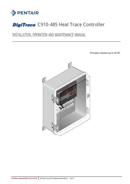
C<strong>910</strong>-485 Heat Trace Controller<br />
INSTALLATION, OPERATION AND MAINTENANCE MANUAL<br />
THERMAL MANAGEMENT SOLUTIONS EN-DigiTraceC<strong>910</strong>-485series-IM-H58415 02/13<br />
Firmware versions up to V4.0X
CONTENTS<br />
Section 1 Overview ...................................................................................................... 3<br />
1.1 Introduction .............................................................................................. 3<br />
1.2 Product Overview ..................................................................................... 3<br />
1.2.1 Description ....................................................................................... 3<br />
1.2.2 Features........................................................................................... 3<br />
1.3 Product Specification ................................................................................ 5<br />
Section 2 Installation and Wiring ................................................................................ 8<br />
2.1 Introduction .............................................................................................. 8<br />
2.2 Initial Inspection ........................................................................................ 8<br />
2.3 Installation Location .................................................................................. 8<br />
2.4 Mounting Procedures ................................................................................ 8<br />
2.5 Wiring....................................................................................................... 9<br />
2.5.1 Power Connections .......................................................................... 9<br />
2.5.2 Temperature Sensor and Extension Cables ..................................... 10<br />
2.5.3 External Device Control/Override .................................................... 10<br />
2.6 Alarm Relay Connections ........................................................................ 11<br />
2.6.1 Communication Signal Connections ................................................ 12<br />
2.7 Initializing the Controller .......................................................................... 13<br />
2.7.1 Initial Heating Cable Test ................................................................ 13<br />
Section 3 Operator Console ...................................................................................... 14<br />
3.1 Alphanumeric Display ............................................................................. 14<br />
3.2 Keypad ................................................................................................... 14<br />
3.3 LED Indicators ........................................................................................ 15<br />
Section 4 C<strong>910</strong>-485 Operation ................................................................................... 16<br />
4.1 Operating Modes .................................................................................... 16<br />
4.1.1 Four Modes of Console................................................................... 16<br />
4.2 Console Mode Menus ............................................................................. 18<br />
4.2.1 Alphanumeric Tag Assignment ........................................................ 19<br />
4.2.2 Setting Units ................................................................................... 20<br />
4.2.3 Switch Control Mode....................................................................... 21<br />
4.2.4 Control Setpoint.............................................................................. 22<br />
4.2.5 Deadband ...................................................................................... 23<br />
4.2.6 Proportional Ambient Sensing Control (PASC) ................................ 24<br />
4.2.7 Low Temperature Alarm: Enable (Lo TS 1 and Lo TS 2) .................. 25<br />
4.2.8 Low Temperature Alarm: Setting (Lo TS 1 and Lo TS 2) .................. 26<br />
4.2.9 High Temperature Alarm: Enable (Hi TS 1 and Hi TS 2) ................... 27<br />
4.2.10 High Temperature Alarm: Setting (Hi TS 1 and Hi TS 2) ................. 28<br />
4.2.11 Temperature Sensor Failure Alarm ................................................ 29<br />
4.2.12 High Temperature Cut-out, Setpoint and Alarm (HI Limit TS1/HI<br />
limitTS2) ................................................................................................. 30<br />
4.2.13 Low Load Current Alarm: Enable (Lo Load) ................................... 31<br />
4.2.14 Low Load Current Alarm: Setting (Lo Load) ................................... 32<br />
4.2.15 Factory Default Settings (Load Defaults) ....................................... 33<br />
4.2.16 Ground-fault Current Alarm level (Hi GF Alarm) ............................. 34<br />
4.2.17 Ground-fault Current Trip Level (Hi GF Trip) .................................. 35<br />
4.2.18 Temperature Sensor Failure Mode ................................................ 36<br />
4.2.19 Temperature Sensor Control Mode (TS CLT Mode) ....................... 37<br />
4.2.20 External Input: Inhibit or Force on. ................................................ 38<br />
4.2.21 Firmware Version ......................................................................... 39<br />
4.2.22 Passcode ..................................................................................... 40<br />
4.2.23 Communications Setup ................................................................. 41<br />
4.2.24 Auto-Cycle: Enabling .................................................................... 43<br />
4.2.25 Auto-Cycle: Interval ...................................................................... 44<br />
4.2.26 Auto-Cycle: Units .......................................................................... 45<br />
4.2.27 Contactor Count ........................................................................... 46<br />
4.2.28 Monitor and Maintenance Menus .................................................. 47<br />
4.2.29 Acknowledging and Resetting Alarms ............................................ 49<br />
4.2.30 Alarm Output Normal State ........................................................... 50<br />
Section 5 Troubleshooting ........................................................................................ 51<br />
Section 6 Appendix A: Proportional Ambient Sensing Control (PASC) ................... 53<br />
THERMAL MANAGEMENT SOLUTIONS EN-DigiTraceC<strong>910</strong>-485series-IM-H58415 02/13 2/54
Section 1<br />
OVERVIEW<br />
1.1 INTRODUCTION<br />
This manual provides information pertaining to the installation, operation, testing and<br />
maintenance of the DigiTrace C<strong>910</strong>-485 Heat Trace Controller.<br />
Additional copies of this user manual may be ordered separately through your <strong>Pentair</strong><br />
<strong>Thermal</strong> <strong>Management</strong> representative or online at www.thermal.pentair.com<br />
This document covers the C<strong>910</strong>-485 Heat Trace Controller and its available options. To<br />
ensure that you are using the correct documentation for your particular version of<br />
controller, please check the firmware version number of your C<strong>910</strong>-485 against the<br />
version number listed on the front of this manual. This may be displayed using the<br />
operator console or a communicating device.<br />
1.2 PRODUCT OVERVIEW<br />
1.2.1 Description<br />
The C<strong>910</strong>-485 Electronic Heat Trace Controller controls, monitors, and communicates<br />
alarms and data for one heating cable circuit. It comes with a RS-485 communication<br />
module for remote operation over Modbus® protocol or in conjunction with the DigiTrace<br />
ACS-30 control system, if desired.<br />
1.2.2 Features<br />
A detailed description of available features may be found in Section 4 of this manual.<br />
Highlights of specific features follow:<br />
Keypad and Alphanumeric Display<br />
A six character alphanumeric LED display provides the operator with large easy to read<br />
messages and prompts, eliminating complex and cryptic programming. Six individual<br />
keys are provided to quickly access alarming and operational information.<br />
40°F to 140°F ( 40°C to 60°C) Operation<br />
Extended temperature operation permits installation in all but the harshest<br />
environments.<br />
Single or Dual Temperature Sensor Inputs<br />
The ability to utilize one or two temperature sensor (TS) inputs allows the selection of<br />
one of eight control modes and programming of all temperature parameters.<br />
High and Low Temperature Alarms<br />
High and low temperature alarms are offered for both temperature sensor inputs of each<br />
control point.<br />
High Temperature Cut-out<br />
High temperature cut-out is provided for both temperature sensor inputs.<br />
Low Current Alarms<br />
The C<strong>910</strong>-485 offers adjustment of the low alarm points over the entire current<br />
measurement range.<br />
Electromechanical Relay (EMR) Output<br />
The C<strong>910</strong>-485 is equipped with a 30-A rated electromechanical relay (EMR) output switch<br />
with device failure alarm.<br />
THERMAL MANAGEMENT SOLUTIONS EN-DigiTraceC<strong>910</strong>-485series-IM-H58415 02/13 3/54
Ground-fault Alarm and Trip<br />
Ground-fault (GF) current levels are monitored and are displayed in milliamperes. The<br />
adjustable ground-fault level gives the user the choice of both alarm and trip levels<br />
suitable for the particular installation.<br />
Proportional Ambient Sensing Control (PASC)<br />
The C<strong>910</strong>-485 includes the Proportional Ambient Sensing Control (PASC) mode to<br />
maximize the energy efficiency of the heat tracing system.<br />
Minimum/Maximum Temperature Tracking<br />
The controller maintains the minimum and maximum temperature values measured<br />
since the last reset of these values.<br />
Temperature Alarms<br />
The controller alarms on user selectable low and high temperature limits.<br />
Auto-cycling<br />
The controller will momentarily energize the circuit (for 10 seconds) at a programmable<br />
interval in order to test the heat tracing circuit during periods of non-use. This feature<br />
will detect issues with the heat-tracing circuit before it can lead to system damage.<br />
Temperature Sensor Failure Alarm<br />
Both open and shorted sensors are detected and alarmed by the controller.<br />
Full Digital Communications<br />
The C<strong>910</strong>-485 incorporates RS-485 serial communication for applications requiring<br />
direct interfacing to BMS systems using Modbus protocol or used as a single circuit<br />
extension to the ACS-30 control system.<br />
Certification<br />
<strong>Pentair</strong> <strong>Thermal</strong> <strong>Management</strong> certifies that this product met its published specifications<br />
at the time of shipment from the factory.<br />
Limited Warranty<br />
This <strong>Pentair</strong> <strong>Thermal</strong> <strong>Management</strong> product is warranted against defects in material and<br />
workmanship for a period of 18 months from the date of installation or 24 months from<br />
the date of purchase, whichever occurs first. During the warranty period, <strong>Pentair</strong><br />
<strong>Thermal</strong> <strong>Management</strong> will, at its option, either repair or replace products that prove to be<br />
defective. For warranty service or repair, this product must be returned to a service<br />
facility designated by <strong>Pentair</strong> <strong>Thermal</strong> <strong>Management</strong>. The Buyer shall prepay shipping<br />
charges to <strong>Pentair</strong> <strong>Thermal</strong> <strong>Management</strong> and <strong>Pentair</strong> <strong>Thermal</strong> <strong>Management</strong> shall pay<br />
shipping charges to return the product to the Buyer. However, the Buyer shall pay all<br />
shipping charges, duties, and taxes for products returned to <strong>Pentair</strong> <strong>Thermal</strong><br />
<strong>Management</strong> from another country. <strong>Pentair</strong> <strong>Thermal</strong> <strong>Management</strong> warrants that the<br />
software and firmware designated by <strong>Pentair</strong> <strong>Thermal</strong> <strong>Management</strong> for use with the<br />
C<strong>910</strong>-485 Controller will execute its programming instructions properly. <strong>Pentair</strong> <strong>Thermal</strong><br />
<strong>Management</strong> does not warrant that the operation of the hardware, or software, or<br />
firmware will be uninterrupted or error-free.<br />
Warranty Exclusion/Disclaimer<br />
The foregoing warranty shall not apply to defects resulting from improper or inadequate<br />
maintenance by the Buyer, Buyer-supplied software or interfacing, unauthorized<br />
modification or misuse, operation outside of the specifications for the product, or<br />
improper installation. No other warranty is expressed or implied. <strong>Pentair</strong> <strong>Thermal</strong><br />
<strong>Management</strong> disclaims the implied warranties of merchantability and fitness for a<br />
particular purpose.<br />
THERMAL MANAGEMENT SOLUTIONS EN-DigiTraceC<strong>910</strong>-485series-IM-H58415 02/13 4/54
Exclusive Remedies<br />
exclusive remedies. <strong>Pentair</strong><br />
<strong>Thermal</strong> <strong>Management</strong> shall not be liable for any direct, indirect, special, incidental, or<br />
consequential damages, whether based on contract, tort, or any other legal theory.<br />
Conducted and Radiated Emissions FCC/DOC Statement of Compliance<br />
This equipment has been tested and found to comply with the limits for a Class A digital<br />
device, pursuant to Part 15 of the FCC rules. These limits are designed to provide<br />
reasonable protection against harmful interference when the equipment is operated in a<br />
commercial environment. This equipment generates, uses, and can radiate radio<br />
frequency energy and, if not installed and used in accordance with the instruction<br />
manual, may cause harmful interference to radio communications. Operation of this<br />
equipment in a residential area is likely to cause harmful interference, in which case the<br />
user will be required to correct the interference at their expense. This equipment does<br />
not exceed Class A limits for radio emissions as set out in Schedule V to VIII of the Radio<br />
Interference Regulations of Communication Canada.<br />
1.3 PRODUCT SPECIFICATION<br />
General<br />
Area of use Nonhazardous locations<br />
Approvals<br />
Supply voltage 100 V to 277 V, +5/ 10%, 50/60 Hz<br />
Enclosure<br />
Protection NEMA 4X<br />
Materials FRP/Polycarbonate<br />
Ambient operating temperature<br />
range<br />
Ambient storage temperature<br />
range<br />
Common supply for controller and heat-tracing circuit<br />
40°F to 140°F ( 40°C to 60°C)<br />
40°F to 185°F ( 40°C to 85°C)<br />
Relative humidity 0% to 90%, noncondensing<br />
Control<br />
Relay type Double-pole, mechanical<br />
Voltage, maximum 277 V nominal, 50/60 Hz<br />
Current, maximum 30 A @ 104°F (40°C) derated to 20 A @ 140°F (60°C)<br />
Control algorithms EMR: On/off, proportional ambient sensing control<br />
(PASC)<br />
THERMAL MANAGEMENT SOLUTIONS EN-DigiTraceC<strong>910</strong>-485series-IM-H58415 02/13 5/54
Control range 0°F to 200°F ( 18°C to 93°C)<br />
Monitoring<br />
Temperature Low alarm range 0°F to 180°F ( 18°C to 82°C) or OFF<br />
High alarm range 0°F to 200°F ( 18°C to 93°C) or OFF<br />
Ground fault Alarm range 20 mA to 100 mA<br />
Trip range 20 mA to 100 mA<br />
Current Low alarm range 0.3 A to 30 A or OFF<br />
Autocycle Diagnostic test interval adjustable from 1 to 240 minutes<br />
or 1 to 240 hours<br />
Temperature Sensor Inputs<br />
Quantity Two inputs standard<br />
Types 100 platinum RTD, 3-wire, = 0.00385 ohms/ohm/°C<br />
Alarm Outputs<br />
Can be extended with a 3-conductor shielded cable of 20<br />
maximum per conductor<br />
AC relay Isolated solid-state triac, SPST, 0.75 A maximum, 100 V<br />
to 277 V nominal<br />
Dry contact relay Pilot duty only, 48 V/dc, 500 mA maximum, 10 VA<br />
maximum resistive switching<br />
Note:<br />
THERMAL MANAGEMENT SOLUTIONS EN-DigiTraceC<strong>910</strong>-485series-IM-H58415 02/13 6/54
Programming and Setting<br />
Method Programmable keypad, or ACS-30 user interface<br />
network<br />
Units Imperial (°F, in.) or Metric (°C, mm)<br />
Digital display Actual temperature, control temperature, heating cable<br />
current, ground fault, programming parameter values,<br />
alarm values<br />
LEDs Current mode, heating cable on, alarm condition,<br />
receive/transmit data<br />
Memory Nonvolatile, restored after power loss, checksum data<br />
checking<br />
Stored parameters (measured) Minimum and maximum temperature, maximum<br />
ground-fault current, maximum heating cable current,<br />
contactor cycle count, time in use<br />
Alarm conditions Low/high temperature, low current<br />
Ground-fault alarm, trip<br />
Other Password protection<br />
Connection Terminals<br />
RTD failure, loss of programmed values, or EMR failure<br />
Power supply input Screw terminals, 22 8 AWG<br />
Heating cable output Screw terminals, 22 8 AWG<br />
Ground Two box lugs, 14 6 AWG<br />
RTD/alarm/communications 28 12 AWG spring clamp terminals<br />
Mounting<br />
FRP/Poly carbonate enclosure Surface mounting with four fixing holes on 7.25 in x 11.7<br />
in (184 mm x 297 mm) centers<br />
Communications<br />
Hole diameter: 0.31 in (8 mm)<br />
Protocol Modbus RTU / ASCII<br />
Topology Multidrop, daisy chain<br />
Cable Single shielded twisted pair, 26 AWG or larger<br />
Length 4,000 ft. (1.3 km) maximum @ 9600 baud<br />
Quantity Up to 32 devices without repeater<br />
Address Programmable<br />
THERMAL MANAGEMENT SOLUTIONS EN-DigiTraceC<strong>910</strong>-485series-IM-H58415 02/13 7/54
Section 2<br />
INSTALLATION AND WIRING<br />
2.1 INTRODUCTION<br />
This section includes information regarding the initial inspection, preparation for use,<br />
and storage instructions for the C<strong>910</strong>-485 Heat Trace controllers.<br />
2.2 INITIAL INSPECTION<br />
Inspect the shipping container for damage. If the shipping container or cushioning<br />
material is damaged, it should be kept until the contents of the shipment have been<br />
verified and the equipment has been checked mechanically and electrically. If the<br />
shipment is incomplete, there is mechanical damage, a defect, or the controller does not<br />
pass the electrical performance tests, notify the nearest <strong>Pentair</strong> <strong>Thermal</strong> <strong>Management</strong><br />
representative. If the shipping container is damaged, or the cushioning material shows<br />
signs of stress, notify the carrier as well as your <strong>Pentair</strong> <strong>Thermal</strong> <strong>Management</strong><br />
representative. Keep the shipping<br />
2.3 INSTALLATION LOCATION<br />
The wide ambient operating temperature range of the controller permits installation in<br />
most locations. Considerations should include accessibility for maintenance and testing<br />
and the location of existing conduits.<br />
2.4 MOUNTING PROCEDURES<br />
The mounting template is shown in Figure 2.1.<br />
Drill conduit entry holes prior to mounting. Conduit entries should be made in the bottom of<br />
the enclosure if possible to reduce the possibility of water entry from condensation or leakage.<br />
Conduit entries must be drilled or punched using standard industry practices. Use bushings<br />
suitable for the environment and install such that the completed installation remains<br />
waterproof. Grounding hubs and conductors must be installed in accordance with Article 250<br />
of the National Electrical Code and Part I of the Canadian Electrical Code.<br />
Figure 2.1 – Mounting Hole Template<br />
THERMAL MANAGEMENT SOLUTIONS EN-DigiTraceC<strong>910</strong>-485series-IM-H58415 02/13 8/54
2.5 WIRING<br />
The following drawings provide sample wiring diagrams for the C<strong>910</strong>-485 control products<br />
and optional accessories. Refer to Figure 2.2 for wiring terminal locations. Please contact<br />
your local <strong>Pentair</strong> <strong>Thermal</strong> <strong>Management</strong> representative for information regarding other<br />
available options.<br />
Figure 2.2 – Power Connection<br />
2.5.1 Power Connections<br />
The C<strong>910</strong>-485 controller may be powered directly from a 100 V to 277 V supply.<br />
All of the power terminals are labeled for easy identification. Do not attempt to use wire<br />
sizes that exceed the marked terminal ratings and avoid terminating two wires on the<br />
same terminal whenever possible.<br />
Note: Make sure that power terminals are retightened several days after installation.<br />
Stranded wire will tend to compress when initially installed; therefore, these terminals<br />
should be checked for tightness several times after the system is installed to ensure that<br />
a good connection is maintained.<br />
Note: Follow the industry standard grounding practices. Do not rely on conduit<br />
connections to provide a suitable ground. Grounding terminals/screws are provided for<br />
connection of system ground leads.<br />
THERMAL MANAGEMENT SOLUTIONS EN-DigiTraceC<strong>910</strong>-485series-IM-H58415 02/13 9/54
C<strong>910</strong> Controller<br />
L1/LINE INPUT<br />
L2/NEUTRAL INPUT<br />
LOAD L1/LINE OUT<br />
LOAD L2/NEUTRAL OUT<br />
Figure 2.3 – Power Connection<br />
2.5.2 Temperature Sensor and Extension Cables<br />
The C<strong>910</strong>-485 has two (2) RTD inputs. Use only 3-<br />
Note: The DigiTrace C<strong>910</strong>-485 default is set for one RTD in position one. If a second RTD<br />
is installed in position two, the controller must be power cycled to recognize the RTD.<br />
Figure 2.4 – Temperature Sensor Wiring<br />
Use shielded, twisted, three-conductor wire for the extension of RTD leads. The wire size<br />
RTD wiring should be grounded at the controller end only, using the terminals provided.<br />
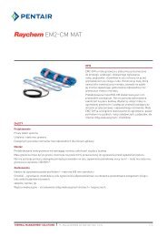
2.5.3 External Device Control/Override<br />
The C<strong>910</strong>-485 controller can be forced on or off using an external device with a dry<br />
contact.<br />
C<strong>910</strong> Controller<br />
C<strong>910</strong> Controller<br />
+12 VDC<br />
EXTERNAL INPUT<br />
COMMON<br />
RTD2<br />
RTD1<br />
+<br />
–<br />
THERMAL MANAGEMENT SOLUTIONS EN-DigiTraceC<strong>910</strong>-485series-IM-H58415 02/13 10/54<br />
3<br />
6<br />
7<br />
4<br />
A<br />
B<br />
C<br />
D<br />
SHIELD<br />
SOURCE<br />
SENSE<br />
COMMON<br />
SHIELD<br />
SOURCE<br />
SENSE<br />
COMMON<br />
L1/LINE<br />
L2/NEUTRAL<br />
19<br />
20<br />
21<br />
22<br />
8<br />
9<br />
10<br />
11<br />
DRAIN<br />
WHT<br />
WHT<br />
RED<br />
DRAIN<br />
WHT<br />
WHT<br />
RED<br />
1 PH INPUT POWER<br />
(100 - 277 VAC nom 50/60 Hz)<br />
100 Ohm<br />
Pt RTD<br />
100 Ohm<br />
Pt RTD<br />
TRACER<br />
EXTERNAL DRY CONTACT<br />
(CLOSE TO ACTIVATE<br />
INHIBIT / OVERRIDE MODE)<br />
(2K Ohms MAX TOTAL LOOP RESISTANCE)<br />
Refer to section 4.2.3 to program<br />
the C<strong>910</strong> for EXT. Direct.<br />
Refer to sections 4.2.20 and section 4.2.21<br />
for programming the C<strong>910</strong> for the Inhibit mode.
Figure 2.5 – Wiring for External Device Control/Override<br />
2.6 ALARM RELAY CONNECTIONS<br />
Two types of alarm relays are provided: One is a DC contact and can be connected as dry<br />
contact (Fig. 2.6) or as a 12 Vdc contact (Figure 2.7). The second is an AC relay (triac) and<br />
can be connected as an alarm relay (Figure 2.8) or a powered alarm relay (Figure 2.9).<br />
Both may be programmed for normally open (N.O.) or normally closed (N.C.) operation.<br />
Note: Both alarm relays are controlled by the C<strong>910</strong>-485 using the same signal.<br />
Note: The dry contact alarm relay is intended to be used for switching low-voltage, lowcurrent<br />
signals. Do not use this relay to directly switch line voltages.<br />
Alarm Output Wiring<br />
C<strong>910</strong> Controller<br />
DRY CONTACT<br />
ALARM RELAY<br />
Figure 2.6 – Used As a Dry Contact<br />
+12 VDC<br />
COMMON<br />
C<strong>910</strong> Controller<br />
DRY CONTACT<br />
ALARM RELAY<br />
+12 VDC<br />
COMMON<br />
Figure 2.7 – Used As a Switched DC Contact<br />
C<strong>910</strong> Controller<br />
L1/LINE OUT<br />
AC (TRIAC)<br />
ALARM RELAY<br />
L2/NEUTRAL OUT<br />
THERMAL MANAGEMENT SOLUTIONS EN-DigiTraceC<strong>910</strong>-485series-IM-H58415 02/13 11/54<br />
3<br />
14<br />
15<br />
4<br />
3<br />
14<br />
15 +<br />
4<br />
1<br />
12<br />
13<br />
2<br />
See Specifications for<br />
Max DC Voltage and Current<br />
DC Power Source<br />
ALARM<br />
Indicator<br />
- ALARM<br />
Indicator<br />
See Specifications for<br />
Max AC Voltage and Current<br />
AC Power Source<br />
ALARM<br />
Indicator
Figure 2.8 – Used As an AC Alarm Relay<br />
C<strong>910</strong> Controller<br />
DRY CONTACT<br />
ALARM RELAY<br />
+12 VDC<br />
COMMON<br />
Figure 2.-9 – Used As a Powered AC Alarm Relay<br />
C<strong>910</strong> Controller<br />
L1/LINE OUT<br />
AC (TRIAC)<br />
ALARM RELAY<br />
L2/NEUTRAL OUT<br />
Figure 2.10 – Used As an AC Alarm Relay<br />
C<strong>910</strong> Controller<br />
L1/LINE OUT<br />
AC (TRIAC)<br />
ALARM RELAY<br />
L2/NEUTRAL OUT<br />
Figure 2.11 – Used as a Powered AC Alarm Relay<br />
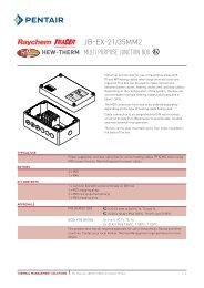
2.6.1 Communication Signal Connections<br />
The C<strong>910</strong>-485 controller includes a RS-485 communications interface. Use twisted pair,<br />
shielded cable communication wiring. Ground the shield on communications wiring at<br />
one end only, using the terminals provided.<br />
THERMAL MANAGEMENT SOLUTIONS EN-DigiTraceC<strong>910</strong>-485series-IM-H58415 02/13 12/54<br />
3<br />
14<br />
15 +<br />
4<br />
1<br />
12<br />
13<br />
2<br />
1<br />
12<br />
13<br />
2<br />
- ALARM<br />
Indicator<br />
See Specifications for<br />
Max AC Voltage and Current<br />
AC Power Source<br />
ALARM<br />
Indicator<br />
ALARM<br />
Indicator
C<strong>910</strong> Controller<br />
Figure 2.12 – Communication Wiring (C<strong>910</strong>-485 only) RS-485 (2-Wire) Connections<br />
2.7 INITIALIZING THE CONTROLLER<br />
2.7.1 Initial Heating Cable Test<br />
COMM. A<br />
COMM. B<br />
GROUND<br />
To minimize the risk of damage to the controller due to a heating cable fault, the integrity<br />
of the heating cable should be verified by performing the commissioning tests detailed in<br />
the appropriate product installation and operating manual. These manuals can be found<br />
on www.thermal.pentair.com<br />
These tests must be performed with the controller output disconnected. Once the cable<br />
has been checked, it may be reconnected to the controller and power applied.<br />
THERMAL MANAGEMENT SOLUTIONS EN-DigiTraceC<strong>910</strong>-485series-IM-H58415 02/13 13/54<br />
16<br />
17<br />
DRAIN<br />
18<br />
DATA +<br />
DATA -
Section 3<br />
OPERATOR CONSOLE<br />
3.1 ALPHANUMERIC DISPLAY<br />
The console incorporates a six characters, fourteen segment, plus decimal LED display.<br />
Messages and prompts that are greater than six characters long are scrolled, allowing<br />
more meaningful, non-cryptic messages to be used.<br />
3.2 KEYPAD<br />
The local keypad consists of six keys that allow you to select the console mode function<br />
that you are interested in. For certain keys, the SHIFT key selects an alternate function,<br />
as shown by the text above that key. When connected to the ACS-30 control system, the<br />
key pad is locked out and will display "Remote Control".<br />
Figure 3.1 – Keypad<br />
Key Function<br />
SHIFT Press to activate a shifted function; the next key pressed uses the<br />
alternate (shifted) function (ALARM, MONITOR and CONFIG).<br />
The SHIFT LED illuminates, indicating the next key uses the<br />
alternate (shifted) function.<br />
Pressing SHIFT again cancels the alternate (shifted) function.<br />
TEST Turns on heating cable circuit for 30 seconds.<br />
SHIFT + TEST Switches the console to the Alarm/reset mode.<br />
BACK Exits the current menu (or cancels the new setting when editing a<br />
parameter)<br />
ENTER<br />
Moves the cursor to the left when editing an alphanumeric<br />
parameter.<br />
[SHIFT + MONITOR] Switches the console to the Monitor mode.<br />
Selects the item in the display (or accepts the setting when editing a<br />
parameter).<br />
Moves the cursor to the right when editing an alphanumeric<br />
parameter.<br />
[shift + CONFIG] Switches the console to the CONFIG mode.<br />
Moves to the previous item in a menu.<br />
Increments the value when editing.<br />
Moves to the next item in a menu.<br />
Decrements the value when editing.<br />
THERMAL MANAGEMENT SOLUTIONS EN-DigiTraceC<strong>910</strong>-485series-IM-H58415 02/13 14/54
Up/Down Arrow<br />
Keys<br />
3.3 LED INDICATORS<br />
Once the main menu has been entered, use the Up/down arrow keys<br />
to navigate the program options.<br />
The console includes eight LED indicators:<br />
Four LEDs indicate the console operating mode (SHIFTed function, ALARM, MONITOR, or<br />
CONFIGure modes).<br />
Two status LEDs indicate the alarm and control output status of the controller:<br />
The OUTPUT LED, when illuminated steadily, indicates that the output of the<br />
controller is turned on and is allowing current to flow into the heating cable circuit.<br />
The ALARM LED will flash (approximately once per second) when the controller has<br />
detected an alarm condition.<br />
Two additional LEDs are used to indicate external communications activity and are only<br />
used with the C<strong>910</strong>-485 with the optional RS-485 communications interface.<br />
Rx that the Controller is receiving information via its<br />
communications port.<br />
Tx flashes when the Controller is transmitting information via its<br />
communications port.<br />
Figure 3.2 – Operator Console<br />
THERMAL MANAGEMENT SOLUTIONS EN-DigiTraceC<strong>910</strong>-485series-IM-H58415 02/13 15/54
Section 4<br />
C<strong>910</strong>-485 OPERATION<br />
4.1 OPERATING MODES<br />
4.1.1 Four Modes on Console<br />
Scan<br />
This is the default mode displayed during normal operation. In this mode, the console<br />
sequentially displays load current, temperature, and setpoint readings.<br />
Alarm<br />
This mode allows you to examine or reset any alarms that may exist. The LED above the<br />
ALARM key is illuminated while in this mode. To enter this mode:<br />
SHIFT<br />
SHIFT<br />
Monitor<br />
This mode allows you to examine any of the controller readings such as temperature,<br />
load current, etc. The LED above the MONITOR key is illuminated while in this mode. To<br />
active this mode:<br />
SHIFT<br />
SHIFT<br />
Configure<br />
Press [SHIFT]<br />
ALARM<br />
TEST<br />
TEST<br />
MONITOR<br />
BACK<br />
BACK<br />
CONFIG<br />
ENTER<br />
Press [TEST]<br />
ALARM MONITOR CONFIG<br />
ENTER<br />
Press [SHIFT]<br />
ALARM<br />
TEST<br />
MONITOR<br />
BACK<br />
CONFIG<br />
ENTER<br />
Press [BACK]<br />
ALARM MONITOR CONFIG<br />
TEST<br />
BACK<br />
ENTER<br />
You are now in the<br />
ALARM screen.<br />
You are now in the<br />
Monitor/Maintenance<br />
menus.<br />
This mode allows you to access the console menus to examine or alter the settings. The<br />
LED above the CONFIG key is illuminated while in this mode. To access the operational<br />
menus:<br />
THERMAL MANAGEMENT SOLUTIONS EN-DigiTraceC<strong>910</strong>-485series-IM-H58415 02/13 16/54
SHIFT<br />
SHIFT<br />
Press [SHIFT]<br />
ALARM<br />
TEST<br />
TEST<br />
MONITOR<br />
BACK<br />
BACK<br />
CONFIG<br />
ENTER<br />
Press [ENTER]<br />
ALARM MONITOR CONFIG<br />
ENTER<br />
You are now in the<br />
Console menus.<br />
THERMAL MANAGEMENT SOLUTIONS EN-DigiTraceC<strong>910</strong>-485series-IM-H58415 02/13 17/54
4.2 CONSOLE MODE MENUS<br />
The Console Mode Menu Index below shows all user interface parameters. This menu<br />
shows the Factory Default along with the associated range. The section column refers to<br />
the section in this manual that illustrates the actual keystrokes required to input the<br />
parameters.<br />
Menu # Section Menu Defaults<br />
1 4.2.1 Tag = 00261439<br />
2 4.2.2 Units = Imperial<br />
3 4.2.3 Switch Control Mode ON /OFF<br />
4 4.2.4 Control Setpoint =<br />
5 4.2.5 Deadband =<br />
6 4.2.6 PASC Setup<br />
7 4.2.7 LO TS 1 = LO TS 2 = DIS<br />
8 4.2.8 LO TS 1 = LO TS 2 =<br />
9 4.2.9 HI TS 1 = HI TS 2 = DIS<br />
10 4.2.10 HI TS 1 = HI TS 2 =<br />
11 4.2.11 TS 2 Fail = DIS<br />
12 4.2.12 TS 1 HI LIMIT = TS 2 HI LIMIT =<br />
TS 1 HI LIMIT Setpoint = TS 2 HI LIMIT Setpoint =<br />
TS 1 HI LIMI Alarm = TS 2 HI LIMI Alarm =<br />
13 4.2.13 LO Load = ENA<br />
14 4.2.14 LO Load = 1.0 A<br />
15 4.2.15 Load Defaults No<br />
16 4.2.16 HI GFI = 20 mA<br />
17 4.2.17 GFI Trip = 30 mA<br />
18 4.2.18 TS Fail Mode = ON<br />
19 4.2.19 TS CTL Mode = TS 1 FAIL ON<br />
20 4.2.20 OVERRIDE Source =<br />
Ext. Input =<br />
THERMAL MANAGEMENT SOLUTIONS EN-DigiTraceC<strong>910</strong>-485series-IM-H58415 02/13 18/54<br />
DIS<br />
DIS<br />
Remote<br />
Not Used<br />
21 4.2.21 Version V4.04.3<br />
22 4.2.22 Passcode = 0<br />
23 4.2.23 Communication Setup HTCbus<br />
24 4.2.24 Auto-Cycle = DIS<br />
25 4.2.25 Auto-Cycle Interval = 8<br />
26 4.2.26 Auto-Cycle Units = Hours<br />
27 4.2.27 Contactor Count = 200000<br />
28 4.2.28 Alarm Output = N.C.<br />
29 4.2.29 Acknowledging/Resetting Alarms N/A<br />
30 4.2.30 Alarm Output Normal State Normally Closed
4.2.1 Alphanumeric Tag Assignment<br />
Purpose A 19 character alphanumeric TAG may be assigned to a control point to<br />
allow it to be easily associated with a pipe, vessel, process, circuit,<br />
drawing name, or number.<br />
Setting Any combination of 19 characters from A Z, 0 9, /, -, ., (, ), or #.<br />
THERMAL MANAGEMENT SOLUTIONS EN-DigiTraceC<strong>910</strong>-485series-IM-H58415 02/13 19/54
4.2.2 Setting Units<br />
Purpose This allows selection of the type units (temperature or size) to display on<br />
the operator.<br />
Setting Metric or Imperial Factory Default Imperial<br />
THERMAL MANAGEMENT SOLUTIONS EN-DigiTraceC<strong>910</strong>-485series-IM-H58415 02/13 20/54
4.2.3 Switch Control Mode<br />
Purpose This allows selection of the type of algorithm to be used to maintain the<br />
control setpoint temperature. Reference Figure 2.5 for the External<br />
Direct wiring schematic.)<br />
Setting On/Off or Proportional Ambient<br />
Sensing Control (PASC), External<br />
Direct<br />
Factory Default On/off<br />
THERMAL MANAGEMENT SOLUTIONS EN-DigiTraceC<strong>910</strong>-485series-IM-H58415 02/13 21/54
4.2.4 Control Setpoint<br />
Purpose This is the temperature that the controller uses to determine whether<br />
its output switch should be on or off.<br />
Setting/Range 0°F to 200°F ( 18°C to 93°C) Factory Default 40°F (4°C)<br />
THERMAL MANAGEMENT SOLUTIONS EN-DigiTraceC<strong>910</strong>-485series-IM-H58415 02/13 22/54
4.2.5 Deadband<br />
Purpose The deadband is a window of difference between the measured<br />
control temperature and the desired control setpoint temperature<br />
and provides the decision to turn the output off or on<br />
Setting/Range 1°F to 10°F (1°C to 6°C) Factory Default 5°F (3°C)<br />
THERMAL MANAGEMENT SOLUTIONS EN-DigiTraceC<strong>910</strong>-485series-IM-H58415 02/13 23/54
4.2.6 Proportional Ambient Sensing Control (PASC)<br />
Purpose This control mode sets Proportional Ambient Sensing Control (PASC). See<br />
Appendix A for more details.<br />
Setting Range Factory Default<br />
Pipe Size (inch): ½-<br />
Control Setpoint: 0 to 200°F ( 18 to 92°C) 40°F (4°C)<br />
Min. Design Ambient: 99 to 125°F ( 73 to 52°C) 40°F ( 40°C)<br />
Power Adjust Factor: 10 200% 100%<br />
THERMAL MANAGEMENT SOLUTIONS EN-DigiTraceC<strong>910</strong>-485series-IM-H58415 02/13 24/54
4.2.7 Low Temperature Alarm: Enable (Lo TS 1 and Lo TS 2)<br />
Purpose This allows the user to enable or disable the low temperature alarm for<br />
temperature sensor number 1 and 2.<br />
Alarm time delay filter is factory set at 15 minutes.<br />
Setting/Range Enable or disable Factory Default Enable<br />
THERMAL MANAGEMENT SOLUTIONS EN-DigiTraceC<strong>910</strong>-485series-IM-H58415 02/13 25/54
4.2.8 Low Temperature Alarm: Setting (Lo TS 1 and Lo TS 2)<br />
Purpose This allows the user to set the low temperature alarm setting for<br />
temperature sensor number 1 and 2.<br />
Alarm time delay filter is factory set at 15 minutes.<br />
Setting/Range 0°F to 180°F ( 18 to 82°C) Factory Default 35°F (2°C)<br />
THERMAL MANAGEMENT SOLUTIONS EN-DigiTraceC<strong>910</strong>-485series-IM-H58415 02/13 26/54
4.2.9 High Temperature Alarm: Enable (Hi TS 1 and Hi TS 2)<br />
Purpose This allows the user to enable or disable the high temperature alarm<br />
for temperature sensor number 1 and 2. When enabled, high limit<br />
cutout feature will force the controller output off if the temperature<br />
reading exceeds the HIGH ALARM temperature setting. This is a nonlatching<br />
condition, so once the reading drops below the HIGH<br />
temperature ALARM setting, the controller will resume normal<br />
operation.<br />
Alarm time delay filter is factory set at 15 minutes.<br />
Setting/Range Enable or disable Factory Default Disable<br />
THERMAL MANAGEMENT SOLUTIONS EN-DigiTraceC<strong>910</strong>-485series-IM-H58415 02/13 27/54
4.2.10 High Temperature Alarm: Setting (Hi TS 1 and Hi TS 2)<br />
Purpose This allows the user to set the high temperature alarm Setting for<br />
temperature sensor number 1 and 2.<br />
Alarm time delay filter is factory set at 15 minutes.<br />
Setting/Range 0°F to 200°F ( 18° to 93°C) Factory Default 180°F (82°C)<br />
THERMAL MANAGEMENT SOLUTIONS EN-DigiTraceC<strong>910</strong>-485series-IM-H58415 02/13 28/54
4.2.11 Temperature Sensor Failure Alarm<br />
Purpose This allows the user to enable or disable the temperature sensor<br />
failure alarm.<br />
Alarm time delay filter is factory set < 2 minutes.<br />
Setting/Range Enable or disable Factory Default Disable<br />
THERMAL MANAGEMENT SOLUTIONS EN-DigiTraceC<strong>910</strong>-485series-IM-H58415 02/13 29/54
4.2.12 High Temperature Cut-out, Setpoint and Alarm<br />
(HI Limit TS1/HI limitTS2)<br />
Purpose Set high temperature alarm and cut-out values.<br />
Settings/Ranges:<br />
Enable/Disable HI Limit<br />
Set point: 0°F (-18°C) to 200°F (93°C)<br />
Enable/Disable Alarm<br />
Factory Defaults:<br />
Disable<br />
200°F (93°C)<br />
Disable<br />
THERMAL MANAGEMENT SOLUTIONS EN-DigiTraceC<strong>910</strong>-485series-IM-H58415 02/13 30/54
4.2.13 Low Load Current Alarm: Enable (Lo Load)<br />
Purpose This allows the user to enable or disable the low load current alarm<br />
to detect current levels which are lower than a preset limit for the<br />
application.<br />
Alarm time delay filter is factory set at < 2 minutes.<br />
Setting/Range Enable or disable Factory Default Enable<br />
THERMAL MANAGEMENT SOLUTIONS EN-DigiTraceC<strong>910</strong>-485series-IM-H58415 02/13 31/54
4.2.14 Low Load Current Alarm: Setting (Lo Load)<br />
Purpose This allows the user to set the low load current alarm level.<br />
Alarm time delay filter is factory set at < 2 minutes.<br />
Setting/Range 0.3 A to 30 A or off Factory Default 1 A<br />
THERMAL MANAGEMENT SOLUTIONS EN-DigiTraceC<strong>910</strong>-485series-IM-H58415 02/13 32/54
4.2.15 Factory Default Settings (Load Defaults)<br />
Purpose To provide a quick method of re-Setting tion<br />
parameters to the Factory Default parameters.<br />
Setting N/A Factory Default N/A<br />
THERMAL MANAGEMENT SOLUTIONS EN-DigiTraceC<strong>910</strong>-485series-IM-H58415 02/13 33/54
4.2.16 Ground-fault Current Alarm level (Hi GF Alarm)<br />
Purpose This allows the user to set the ground-fault current alarm level.<br />
Exceeding this limit will trigger the alarm to indicate that a groundfault<br />
condition exists in the heating cable circuit. To protect against<br />
the risk of fire or shock, ground-fault level should be set at the<br />
lowest level possible to allow normal operation of the cable.<br />
Alarm time delay filter is factory set as immediate<br />
Setting/Range 20 mA to 100 mA Factory Default 20 mA<br />
THERMAL MANAGEMENT SOLUTIONS EN-DigiTraceC<strong>910</strong>-485series-IM-H58415 02/13 34/54
4.2.17 Ground-fault Current Trip Level (Hi GF Trip)<br />
Purpose This allows the user to set the ground-fault current trip level.<br />
Exceeding this limit will result in the output switch being latched off<br />
and the Ground-fault Level Trip Alarm activated to indicate a ground<br />
fault condition.<br />
WARNING: Fire Hazard. Ground-fault trip alarms must not be<br />
ignored. To prevent the risk of fire, do not re-energize heating cables<br />
until the fault is identified and corrected.<br />
Alarm time delay filter is factory set as immediate<br />
Setting/Range 20 mA to 100 mA Factory Default 30 mA<br />
THERMAL MANAGEMENT SOLUTIONS EN-DigiTraceC<strong>910</strong>-485series-IM-H58415 02/13 35/54
4.2.18 Temperature Sensor Failure Mode<br />
Purpose This mode sets the controller to turn the output switch ON or OFF if<br />
all selected temperature sensors fail.<br />
Setting/Range On or off Factory Default On<br />
THERMAL MANAGEMENT SOLUTIONS EN-DigiTraceC<strong>910</strong>-485series-IM-H58415 02/13 36/54
4.2.19 Temperature Sensor Control Mode (TS CLT Mode)<br />
Purpose The TS CONTROL MODE allows the selection of one of eight<br />
possible temperature control modes for the controller. The<br />
different modes allow redundant fail-safe temperature sensing.<br />
Setting/Range 1. TS1-Fail ON<br />
2. Lowest Fail to Good<br />
3. Lowest Fail ON<br />
4. Average Fail to Good<br />
Factory Default TS1-Fail On<br />
5. Average Fail ON<br />
6. TS2 Fail to TS1<br />
7. TS2 Fail ON<br />
8. TS1 Fail to TS2<br />
THERMAL MANAGEMENT SOLUTIONS EN-DigiTraceC<strong>910</strong>-485series-IM-H58415 02/13 37/54
4.2.20 External Input: Inhibit or Force on.<br />
Purpose Using an external input device to override sensor inputs: Force on or<br />
force off. Reference Figure 2.5 for the wiring connection schematic.<br />
Setting/Range<br />
Ext Input: Not used, Force on or Inhibit<br />
Override: Remote or External input<br />
Factory Default<br />
Not used<br />
Remote<br />
THERMAL MANAGEMENT SOLUTIONS EN-DigiTraceC<strong>910</strong>-485series-IM-H58415 02/13 38/54
4.2.21 Firmware Version<br />
Purpose This menu displays the revision level of the firmware programmed<br />
into the controller.<br />
Setting/Range N/A Factory Default N/A<br />
THERMAL MANAGEMENT SOLUTIONS EN-DigiTraceC<strong>910</strong>-485series-IM-H58415 02/13 39/54
4.2.22 Passcode<br />
Purpose The four digit numeric PASSWORD stops unauthorized users from<br />
Operator Console.<br />
Setting/Range 0000 to 9999 Factory Default 0000<br />
THERMAL MANAGEMENT SOLUTIONS EN-DigiTraceC<strong>910</strong>-485series-IM-H58415 02/13 40/54
4.2.23 Communications Setup<br />
Purpose Defines the communications language used by the controller to<br />
communicate with other devices. The C<strong>910</strong>-485 only communicates<br />
using Modbus Protocol. The C<strong>910</strong>-485 automatically detects when it<br />
is connected to the ACS-30 network.<br />
Setting/Range See C<strong>910</strong>-485<br />
Communication Parameters<br />
Table<br />
Factory Default HTCBus<br />
THERMAL MANAGEMENT SOLUTIONS EN-DigiTraceC<strong>910</strong>-485series-IM-H58415 02/13 41/54
C<strong>910</strong>-485 Communication Parameters<br />
Parameter Settings Notes<br />
Protocol HTCBus (default)<br />
Modbus RTU<br />
Modbus ASCII<br />
If you are communicating directly with the<br />
controller using a different device, select the<br />
MODBUS protocol.<br />
MODBUS mapping please refer to C<strong>910</strong>-485 Heat<br />
Trace Controller.<br />
Note: HTCBus is for factory use only.<br />
Modbus Addr 1 - 247 Set the communications address as desired. Each<br />
Modbus Baud<br />
Rate<br />
Auto, 9600, 4800,<br />
2400<br />
1200, 600, 300.<br />
Default =Auto<br />
controller on the serial communication bus must<br />
have its own unique address.<br />
Select the data rate to be compatible with other<br />
devices that will be connected to the controller for<br />
communications Purposes. It is recommended that<br />
the Setting be set to AUTO. The controller will<br />
automatically select a BAUD RATE that is<br />
compatible with the communications interface<br />
installed.<br />
Parity NONE, EVEN, ODD Defines the type of parity bit to be used with<br />
MODBUS communications.<br />
Select the desired type of parity. Note that PARITY<br />
can only be selected when using MODBUS<br />
protocol.<br />
Hardware RS-485 Identifies the type of communications interface<br />
installed in the C<strong>910</strong>-485.<br />
Driver Auto, RS-485, RS-<br />
232, Modem. communicates with the communications interface.<br />
Profile Auto, 3-wire RS232,<br />
RS485, 1200 BAUD<br />
Modem, 300 BAUD<br />
Modem<br />
Tx Delay 0.00 to 2.50<br />
seconds<br />
supports communications handshaking and<br />
communication interface signals.<br />
Allows a programmable delay between the receipt<br />
of a communications message<br />
reply. In some applications, it may be necessary to<br />
short period of time to allow external devices to<br />
start up, stabilize and/or synchronize.<br />
THERMAL MANAGEMENT SOLUTIONS EN-DigiTraceC<strong>910</strong>-485series-IM-H58415 02/13 42/54
4.2.24 Auto-Cycle: Enabling<br />
Purpose The autocycle function applies power to the heating cable circuit for<br />
approximate 10 seconds at the selected interval. It is used to test the<br />
integrity of the heating cable circuit.<br />
Note: Although the autocycle function helps monitor the<br />
functionality of the heating cable circuits it does not eliminate the<br />
need for preventive maintenance as detailed in the heating cable<br />
operating manuals.<br />
Setting/Range Enable or disable Factory Default Disable<br />
THERMAL MANAGEMENT SOLUTIONS EN-DigiTraceC<strong>910</strong>-485series-IM-H58415 02/13 43/54
4.2.25 Auto-Cycle: Interval<br />
Purpose Set the interval for running the autocycle procedure<br />
Setting/Range 1 to 240 [minutes or hours, selected<br />
in the Auto-cycle units menu.]<br />
Factory Default 8<br />
THERMAL MANAGEMENT SOLUTIONS EN-DigiTraceC<strong>910</strong>-485series-IM-H58415 02/13 44/54
4.2.26 Auto-Cycle: Units<br />
Purpose Select the Autocycle interval time units.<br />
Setting/Range Minutes or hours Factory Default Hours<br />
THERMAL MANAGEMENT SOLUTIONS EN-DigiTraceC<strong>910</strong>-485series-IM-H58415 02/13 45/54
4.2.27 Contactor Count<br />
Purpose Generates an alarm if the number of off-to-on transitions of a<br />
contactor reaches or exceeds the Contactor Count Alarm Setting. This<br />
serves as a method to perform preventative maintenance on the<br />
contactor before a failure is likely to occur.<br />
Setting/Range 0 to 999,999 Factory Default 200,000<br />
THERMAL MANAGEMENT SOLUTIONS EN-DigiTraceC<strong>910</strong>-485series-IM-H58415 02/13 46/54
4.2.28 Monitor and Maintenance Menus<br />
Purpose The Monitor menu displays the measured and stored readings. You<br />
can also reset counters from this menu.<br />
Setting/Range See C<strong>910</strong>-485 Monitoring<br />
and Maintenance<br />
Parameters table.<br />
Factory Default N/A<br />
THERMAL MANAGEMENT SOLUTIONS EN-DigiTraceC<strong>910</strong>-485series-IM-H58415 02/13 47/54
DigiTrace <strong>910</strong> Monitoring and Maintenance Parameters<br />
Monitored variables Description<br />
CTL temp Control Temp<br />
TS1 temp This temperature is the value that the controller is<br />
reading from the RTD connected to its TS 1 input.<br />
TS2 temp This temperature is the value that the controller is<br />
reading from the RTD connected to its TS 2 input, if the<br />
sensor is being used.<br />
Load current Displays the current being drawn by the heating cable.<br />
(A)<br />
GFI current Displays the ground-fault current being drawn by the<br />
heating cable. (mA)<br />
Maintenance Tests<br />
Trace testing The TEST TRACING feature temporarily overrides the<br />
temperature control, and powers the heating cable<br />
circuit for 30 seconds without having to modify the<br />
CONTROL SETPOINT temperature or any other<br />
configuration parameter.<br />
Display test The DISPLAY TEST feature provides an easy method of<br />
illuminating each display segment and all the LEDs of<br />
Recorded Values<br />
the Operator Console to ensure that they are functioning<br />
properly.<br />
Temperature values This feature indicates the maximum and minimum<br />
temperatures recorded by the C<strong>910</strong>-485 since the last<br />
time the values were reset:<br />
Max Control temp<br />
Min Control temp<br />
TS 1 Max Temp<br />
TS 1 Min Temp<br />
TS 2 Max Temp<br />
TS 2 Min Temp<br />
Contactor cycle count This feature indicates the total number of off-to-on<br />
transitions a contactor has made since the last time the<br />
CONTACTOR CYCLE COUNTER was reset. (See<br />
keystroke procedure for resetting)<br />
Time in use Indicates the total hours in use of the controller since<br />
its initial operation or since it was last reset.<br />
Time since last reset This feature indicates the total hours in use of the<br />
controller since the last reset.<br />
Peak ground-fault current This feature indicates the highest instantaneous<br />
ground-fault current measured since the last time the<br />
PEAK GROUND-FAULT CURRENT was reset. This<br />
-volatile<br />
memory once every 24 hours or whenever any<br />
maintenance data is reset by the user.<br />
THERMAL MANAGEMENT SOLUTIONS EN-DigiTraceC<strong>910</strong>-485series-IM-H58415 02/13 48/54
4.2.29 Acknowledging and Resetting Alarms<br />
Purpose To acknowledge and reset any alarm conditions that may exist. Use<br />
the Up / Down Arrow keys to examine the next/previous active<br />
alarms.<br />
Setting/Range See Alarm Filter Times Factory Default N/A<br />
Alarm Filter Times<br />
Alarm Type Filter Time<br />
Lo TS 1 and 2 15 minutes<br />
Hi TS 1 and 2 15 minutes<br />
Lo load current 2 minutes<br />
Hi ground-fault alarm 10 seconds<br />
Hi ground-fault trip < 1 second<br />
OPEN / SHORTED TS 1 and 2 10 seconds<br />
Contactor count < 1 seconds<br />
Switch failure 2 minutes<br />
THERMAL MANAGEMENT SOLUTIONS EN-DigiTraceC<strong>910</strong>-485series-IM-H58415 02/13 49/54
4.2.30 Alarm Output Normal State<br />
Purpose Configures both the alarm output relays (dry contact and AC alarm)<br />
for normally open or normally closed operation. The normal<br />
condition is assumed to be when the HTC is powered and no alarms<br />
exist.<br />
Setting/Range Normally Open (N.O.) or<br />
Normally Closed (N.C.)<br />
Factory Default Normally closed<br />
THERMAL MANAGEMENT SOLUTIONS EN-DigiTraceC<strong>910</strong>-485series-IM-H58415 02/13 50/54
Section 5<br />
TROUBLESHOOTING<br />
The C<strong>910</strong>-485 may be used as an effective troubleshooting tool to pinpoint problem areas<br />
of heating cable circuits. Described below are a few of the more common problem areas,<br />
their symptoms, and parameters to check to determine the actual faulty portion of the<br />
heating cable circuit.<br />
Symptom Probable Cause Corrective Action<br />
RTD failure alarm RTD is not a 3-wire 100<br />
Seemingly<br />
incorrect<br />
temperature<br />
Unstable or<br />
bouncing<br />
temperature<br />
High temperature<br />
TS 1/ TS 2<br />
LOW temperature<br />
TS 1/TS 2<br />
Install correct RTD<br />
Damaged RTD sensor or Install new RTD and/or cable<br />
extension cable<br />
Incorrectly wired Re-install RTD connections<br />
Incorrect RTD used Install correct RTD<br />
Damaged RTD sensor<br />
or connection cable<br />
C<strong>910</strong>-485 not<br />
functioning correctly<br />
Bad, damaged or<br />
incorrectly installed<br />
RTD extension wire.<br />
Terminal connections<br />
are not tight<br />
RTD or extension cable<br />
damaged<br />
Alarm temperature<br />
setting too close to<br />
maintain temperature<br />
Flow of hot water<br />
through pipe<br />
Incorrect heating cable<br />
wiring<br />
Alarm temperature<br />
setting too close to<br />
maintain temperature<br />
Heating cable not sized<br />
properly for the<br />
application<br />
Damaged, wet, or<br />
missing thermal<br />
insulation<br />
Control TS failure Failure of the RTD<br />
designated as the<br />
controlling sensor.<br />
Install new RTD and/or cable<br />
Verify correct reading input Connect a<br />
100 resistor across the source or sense<br />
terminal and common. Insert a jumper<br />
between the source and sense terminals.<br />
Apply power to the controller. The<br />
indicated or displayed temperature should<br />
be about 32°F (0°C).<br />
Wire used for extension of the RTD should<br />
be three-wire, twisted and shielded with<br />
the shield grounded at the controller only.<br />
Each of the three lead wires must be of<br />
the same gauge.<br />
Verify tightness of connections<br />
Install new RTD and/or cable<br />
Increase setting<br />
Verify heating cable wiring<br />
Decrease setting<br />
Refer to the appropriate heating cable<br />
design guide for correct product selection<br />
Replace or install correct thermal<br />
insulation<br />
Check setting for TS FAIL MODE the<br />
output switch may be latched off or on<br />
until this failure is corrected<br />
THERMAL MANAGEMENT SOLUTIONS EN-DigiTraceC<strong>910</strong>-485series-IM-H58415 02/13 51/54
Ground-fault<br />
alarms<br />
Incorrect or damaged<br />
field wiring<br />
Damaged temperature<br />
sensors<br />
Incorrect installation,<br />
wet system<br />
components or<br />
damaged cables.<br />
Incorrect neutral return<br />
wiring<br />
Alarm setting too close<br />
to normal leakage<br />
current<br />
Low current Low or no source<br />
Re-install RTD connections<br />
Install correct RTD.<br />
Perform heating cable commissioning<br />
tests outlined in the heat cable operation<br />
manuals.<br />
Check that the heating cable circuit<br />
neutrals return to the controller and are<br />
not connected directly to the distribution<br />
THERMAL MANAGEMENT SOLUTIONS EN-DigiTraceC<strong>910</strong>-485series-IM-H58415 02/13 52/54<br />
panel.<br />
Ground-fault level should be set at the<br />
lowest level possible, but high enough to<br />
allow normal operation of the cable.<br />
WARNING: Fire Hazard. Ground-fault trip alarms must not be<br />
ignored. To prevent the risk of fire, do not re-energize heating<br />
cables until the fault is identified and corrected.<br />
voltage<br />
Damaged or inoperative<br />
heating cable<br />
Open connection<br />
wiring problem<br />
Verify correct power distribution<br />
Repair or replace heating cable<br />
Verify correct power distribution wiring<br />
Contactor failed open Replace or repair controller<br />
Switch failure Output switch has failed<br />
Contactor count Number of off-to-on<br />
transitions of a<br />
contactor has exceeded<br />
the CONTACTOR<br />
COUNT ALARM setting<br />
and the contactor<br />
should be replaced.<br />
Replace or repair controller<br />
Inspect contactor and replace if<br />
necessary.
Section 6<br />
APPENDIX A: PROPORTIONAL AMBIENT SENSING CONTROL (PASC)<br />
PASC takes advantage of the fact that the heat loss from a pipe is proportional to the<br />
temperature difference between the pipe and the ambient air. This is true regardless of<br />
heating cable, insulation type, or pipe size. Once the heat tracing and insulation on a<br />
pipe has been designed to balance heat input with heat loss and maintain a particular<br />
temperature, the main variable in controlling the pipe temperature becomes the<br />
ambient air temperature.<br />
The C<strong>910</strong>-485 has a control algorithm that uses the measured ambient temperature,<br />
desired maintain temperature, minimum ambient temperature assumption used during<br />
design, and size of the smallest pipe diameter to calculate how long the heating cable<br />
should be on or off to maintain a near-constant pipe temperature. The power to the heat<br />
tracing is proportioned based upon on the ambient temperature. If the ambient<br />
of the time equal to (maintain temperature measured ambient) / (maintain<br />
temperature minimum design temperature).<br />
THERMAL MANAGEMENT SOLUTIONS EN-DigiTraceC<strong>910</strong>-485series-IM-H58415 02/13 53/54<br />
ture
NORTH AMERICA<br />
Tel: +1.800.545.6258<br />
Fax: +1.800.527.5703<br />
Tel: +1.650.216.1526<br />
Fax: +1.650.474.7711<br />
thermal.info@pentair.com<br />
EUROPE, MIDDLE EAST, AFRICA<br />
Tel: +32.16.213.511<br />
Fax: +32.16.213.603<br />
thermal.info@pentair.com<br />
ASIA PACIFIC<br />
Tel: +86.21.2412.1688<br />
Fax: +86.21.5426.2917<br />
cn.thermal.info@pentair.com<br />
LATIN AMERICA<br />
Tel: +55.11.2588.1400<br />
Fax: +55.11.2588.1410<br />
thermal.info@pentair.com<br />
<strong>Pentair</strong> and DigiTrace are owned by <strong>Pentair</strong> or its global affiliates. All other trademarks are the property of their respective owners. <strong>Pentair</strong> reserves the<br />
right to change specifications without prior notice.<br />
© 2009 2013 <strong>Pentair</strong>.<br />
WWW.THERMAL.PENTAIR.COM<br />
THERMAL MANAGEMENT SOLUTIONS EN-DigiTraceC<strong>910</strong>-485series-IM-H58415 02/13 54/54