SmartForm Brochure - Tilling Timber
SmartForm Brochure - Tilling Timber
SmartForm Brochure - Tilling Timber

You also want an ePaper? Increase the reach of your titles
YUMPU automatically turns print PDFs into web optimized ePapers that Google loves.
STRONGER ACRYLIC COATING LIGHTWEIGHT CONSISTENCY SUSTAINABLE 6M+ LENGTHS<br />
<strong>SmartForm</strong><br />
Form<br />
1<br />
2010
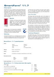
Description<br />
<strong>SmartForm</strong> 11.7 LVL is a Douglas Fir structural laminated<br />
veneer lumber (LVL) manufactured by Pacific Woodtech Corporation<br />
Washington State USA to meet the requirements of<br />
AS/NZS 4357 - Structural Laminated Veneer Lumber. It is<br />
produced in industry standard sizes, painted safety yellow for<br />
easy visual identification, and is intended for use as concrete<br />
formwork support structures<br />
such as joists, bearers, walers<br />
and soldiers.<br />
Quality<br />
<strong>SmartForm</strong> 11.7 is manufactured<br />
for <strong>Tilling</strong> <strong>Timber</strong> Pty Ltd under an<br />
evergreen exclusive agreement<br />
with the worlds best toll LVL manufacturer<br />
under the benchmark<br />
quality systems of the APA - The<br />
Engineered Wood Association.<br />
APA – The Engineered Wood Association<br />
is an accredited certification<br />
body under ISO 65 by<br />
Standards Council of Canada (SCC) and an accredited inspection<br />
agency by the International Code Council (ICC), International<br />
Accreditation Service (IAS) under ISO/IEC 17020. APA is<br />
also an accredited testing organisation recognised by IAS and<br />
SCC under ISO/IEC 17025.<br />
Marking<br />
Each piece of <strong>SmartForm</strong> 11.7 is branded at least once with<br />
the <strong>SmartForm</strong> branding compliant with AS/NZS 4357 structural<br />
LVL standard for identification and evidence of compliance<br />
with manufacturing control standards and product quality<br />
<strong>SmartForm</strong> 11.7 Specifications<br />
certification. It is also sealed with a water resistant yellow<br />
coating to increase its durability, providing the user with extended<br />
lifecycles and superior performance.<br />
Scope of these tables<br />
This Design Guide and load tables assist in the selection of<br />
<strong>SmartForm</strong> 11.7 formwork materials in standard<br />
applications. All load tables in this document<br />
are developed using in-grade tested characteristic<br />
properties of <strong>SmartForm</strong> 11.7 as distributed<br />
by <strong>Tilling</strong> <strong>Timber</strong>. Other look-alike substitution LVL<br />
formwork products manufactured by different<br />
producers may have different properties, and<br />
their specification from these tables may create<br />
an unsafe support system or unsatisfactory performance.<br />
This publication is therefore strictly limited to the<br />
design of joists and bearers in common formwork<br />
applications. Reference should be made to<br />
AS 3610-1995 plus supplements 1 and 2 and an experienced<br />
structural engineer for methods and details of developing lateral<br />
restraint, providing suitable vertical support to joists and<br />
bearers in the above tables as well as the robustness and<br />
stability of the formwork system as a whole.<br />
Technical Support<br />
This Design Guide covers only the most common formwork<br />
applications. For applications, service classes not covered in<br />
this Design Guide and/or general product enquiries about<br />
<strong>SmartForm</strong> 11.7, please contact SmartFrame technical support<br />
on 1300 668 690 or at smardata@tilling.com.au<br />
Veneer - Species Douglas Fir<br />
- Thickness (normal) 2.5-3.6 mm<br />
- Joints Scarf<br />
- Grade CD—Metriguard Graded<br />
Adhesive Phenolic – Type A AS2754.1<br />
Density Average value 570 kg/m 3<br />
Finish Un-sanded faces, arised edges Painted distinctive “safety” Yellow<br />
Dimensional tolerances - Depth<br />
- Thickness<br />
- Length<br />
Standard supply lengths 6.0, 5.4, 4.8, 4.2, 3.6 and 3.0 metres<br />
<strong>SmartForm</strong> 11.7 Characteristic Strengths<br />
-0 +3.0mm<br />
-0 +3.0 mm<br />
-0, +15 mm<br />
Bending f’ b 50 MPa<br />
Shear (rail shear as per AS/NZS 4357) f’ s 3.1 MPa<br />
Compression perpendicular to grain (bearing) f’p 12 MPa<br />
Characteristic short duration lower 5th percentile *modulus of elasticity E 11,700 MPa<br />
Joint Group JD4<br />
* The lower 5 th percentile Short Duration MOE has been used instead of the more usual average Short Duration MOE in these tables. This does give a<br />
more conservative span. If designers want to use the average Short Duration MOE, they should contact SmartFrame technical support team on 1300<br />
668 690 or at smardata@tilling.com for this value.<br />
<strong>SmartForm</strong> 11.7 Design Guide 1 Edition 1 July 2010
<strong>SmartForm</strong> 11.7 - “F” grade timber<br />
comparison<br />
LVL is an engineered timber product whose characteristic<br />
strength properties are derived by in-grade testing to AS/<br />
NZS 4063. “F”” grades are assigned after visual grading of<br />
the solid timber to the appropriate standards. There is no<br />
direct link between “F” graded timber and in-grade tested<br />
timber.<br />
Design capacities for the table are based upon the following criteria:<br />
<strong>SmartForm</strong> 11.7 Section properties<br />
<strong>SmartForm</strong> size<br />
D x B mm<br />
Self weight<br />
kg/m<br />
Rigidity EI<br />
x 10 9 Nmm 2<br />
• Capacity reduction factor Φ = 0.85 (Primary Structural Elements other than houses table 2.5 AS 1720.1)<br />
• k1 = 0.94 (Duration of 5 days) AS1720.1<br />
• Full lateral restraint<br />
Formwork Design Process<br />
The design of formwork always starts with defining the quality<br />
of the finished concrete surface. This is usually communicated<br />
through the project documents. Surface quality is<br />
effected by the extent to which the formwork components<br />
deflect under the applied loadings. Physical quality and tolerances,<br />
detailed in AS 3610 tables 3.3.1 and 3.4.2 guide<br />
the formwork designer in the selection of formface material<br />
and deflection limits for the framing members for soffits and<br />
wall forms. The tables include the deflection criteria for the<br />
most common classes of finish, namely:<br />
Class 3 - Maximum of 3 mm or<br />
span/270<br />
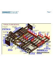
CONVENTIONAL SOFFIT FORMWORK FOR SLABS<br />
Bearer<br />
joist span<br />
plywood<br />
prop spacing and bearer spans<br />
Design Capacity<br />
Bending<br />
ΦM kNm<br />
Shear<br />
ΦV kN<br />
95 x 45 2.4 37.6 2.9 7.5<br />
95 x 63 3.4 52.7 4.0 10.5<br />
150 x 75 6.4 246.8 12.0 19.8<br />
Joist<br />
Prop<br />
Notwithstanding the above, <strong>SmartForm</strong> 11.7 may be used<br />
to safely substitute “F” graded material up to and including<br />
F8.<br />
Span tables for alternative deflection limits are available by<br />
contacting the SmartData Customer HelpLine on 1300 668<br />
690 or at smartdata@tilling.com.au<br />
The design aids in this design guide are confined to the selection<br />
of <strong>SmartForm</strong> 11.7 LVL members which ensure that<br />
the formwork provides the strength and rigidity necessary to<br />
meet both structural safety and surface quality requirements.<br />
Structural safety is limited to the selection of individual<br />
structural components subject to normal concrete pressures.<br />
This design guide does NOT address the structural<br />
safety of the system that may be subject to a wide range of<br />
abnormal and accidental loads. Methods for developing lateral<br />
restraint, providing adequate support as well as the<br />
overall stability of the structure are outside the scope of this<br />
publication.<br />
The members in this table have been designed based upon<br />
the addition of the “Global load factor for primary member”<br />
introduced into AS 3610 - 1995 with Amendment 1 =<br />
2003.<br />
For horizontal members such as bearers and joists for<br />
soffits, both the joists and bearers have been considered<br />
primary members. For vertical forms, the soldiers have<br />
been considered primary members.<br />
<strong>SmartForm</strong> 11.7 Design Guide 2 Edition 1 July 2010
Notes for use with Table<br />
1. Minimum bearing length = 45 mm at<br />
end supports. Subscript values indicate<br />
additional bearing length required<br />
above the minimum of 45 mm<br />
to achieve the stated span<br />
2. Spans in tables have been designed<br />
as per section 4 of AS 3610-1995,<br />
including Amendment 1:2003 for all<br />
stage 1, 2 and 3 loadings. This allows<br />
for a 4.0 KPa imposed load due<br />
to stacked material as a stage 3<br />
loading. This load is considered to be<br />
additional to other live loads. If the<br />
project designer applies limitations to<br />
restrict these material loads to a<br />
lesser amount (as specified in Clause<br />
2.3(b) of AS 3610 - 1995), then<br />
larger spans will be achieved.<br />
3. Since the finish quality is dependent<br />
upon a number of factors including<br />
the formface used and the accuracy<br />
of the setup, a class 3 finish cannot<br />
be guaranteed.<br />
4. For multiple spans, the design has<br />
assumed the most conservative of 2<br />
and 3 spans and that all spans are<br />
essentially equal.<br />
5. The design has assumed that the<br />
joists are continually restrained by the<br />
sheeting and the bearers are restrained<br />
by the joists.<br />
6. The design tables are only suitable for<br />
horizontal forms. For angled soffits,<br />
consult a formwork designer.<br />
7. To satisfy the bearing requirements of<br />
the timber, the breadth of the bearer<br />
must be equal to or greater than the<br />
breadth of the joists it is supporting.<br />
<strong>SmartForm</strong> Joists for Concrete Slab Soffits<br />
Max deflection greater of 3 mm or span/270 - Class 3<br />
Single Span<br />
Joist Slab Joists Spacing (mm)<br />
Size Depth 225 300 400 450 480 600<br />
95x45 100 1900 1700 1500 1500 1400 1300<br />
150 1800 1600 1500 1400 1300 1300<br />
200 1700 1500 1400 1300 1300 1200<br />
300 1600 1400 1300 1200 1200 1100<br />
400 1500 1300 1200 1100 1100 1000<br />
600 1300 1200 1100 1000 1000 NS<br />
1000 1100 1000 NS NS NS NS<br />
95x63 100 2100 1900 1700 1700 1600 1500<br />
150 2000 1800 1600 1600 1500 1400<br />
200 1900 1700 1600 1500 1500 1400<br />
300 1800 1600 1400 1400 1400 1300<br />
400 1600 1500 1300 1300 1300 1200<br />
600 1500 1300 1200 1200 1100 1100<br />
1000 1300 1200 1100 1000 1000 NS<br />
150x75 100 3600 3200 2900 2800 2800 2600<br />
150 3400 3100 27800 2700 2600 2400<br />
200 3200 2900 2600 2500 2500 2300<br />
300 3000 2700 2400 2300 2300 2100<br />
400 2800 2500 2300 2200 2200 2000<br />
600 2500 2300 2100 2000 1900 1800<br />
1000 2200 2000 1800 1700 1700 1600<br />
Continuous Spans<br />
Joist Slab Joists Spacing (mm)<br />
Size Depth 225 300 400 450 480 600<br />
95x45 100 2300 2100 1900 1800 1800 1600<br />
150 2200 2000 1800 1700 1700 1500<br />
200 2100 1900 1700 1700 1600 1300<br />
300 1900 1800 1600 1400 1400 1100<br />
400 1800 1700 1400 1300 1200 1000<br />
600 1600 1400 1100 1000 NS NS<br />
1000 1300 1000 NS NS NS NS<br />
95x63 100 2600 2400 2200 2100 2000 1900<br />
150 2500 2200 2000 2000 1900 1800<br />
200 2400 2100 1900 1900 1800 1700<br />
300 2200 2000 1800 1700 1700 1500<br />
400 2000 1900 1700 1600 1600 1300<br />
600 1900 1700 1500 1300 1300 1100<br />
1000 1600 1400 1100 1000 NS NS<br />
150x75 100 4400 4000 3600 3500 3400 3200<br />
150 4200 3800 3400 3300 3200 3000<br />
200 4000 3600 3300 3200 3100 2900<br />
300 3700 3300 3000 2900 2900 2700<br />
400 3500 3100 2800 2700 2700 2400<br />
600 3100 2800 2600 2400 2300 1900<br />
1000 2700 2500 2000 1800 1700 1400<br />
<strong>SmartForm</strong> 11.7 Design Guide 3 Edition 1 July 2010
<strong>SmartForm</strong> Bearers for Concrete Slab Soffits<br />
Max deflection greater of 3 mm or span/270 - Class 3<br />
Single Span<br />
Bearer Slab Bearer Spacing<br />
Size Depth 900 1200 1500 1800 2100 2400<br />
95x63 100 1400 1200 1100 1000 900 800<br />
150 1300 1100 1000 1000 800 800<br />
200 1200 1100 1000 900 800 700<br />
300 1100 1000 800 800 700 700<br />
400 1000 900 800 700 600 600<br />
600 900 800 700 600 600 500<br />
1000 700 600 500 500 5005 NS<br />
150x75 100 2400 2100 1900 1800 1700 1500<br />
150 2200 2000 1800 1700 1600 1400<br />
200 2100 1900 1700 1600 1400 1300<br />
300 1900 1700 1600 1400 1200 1200<br />
400 1800 1600 1400 1300 1100 11005<br />
600 1600 1300 1200 1100 5 10005 10005<br />
1000 1300 1100 5 100015 90020 90015 80020<br />
Continuous Spans<br />
Bearer Slab Bearer Spacing<br />
Size Depth 900 1200 1500 1800 2100 2400<br />
95x63 100 1500 1200 1000 800 700 700<br />
150 1400 1100 900 700 700 600<br />
200 1300 1000 800 700 600 500<br />
300 1100 800 800 600 600 NS<br />
400 900 700 500 600 500 NS<br />
600 700 700 NS 500 NS NS<br />
1000 600 500 NS NS NS NS<br />
150x75 100 2800 2200 1900 1600 1400 1300<br />
150 2500 2000 1700 1400 1300 1200<br />
200 2300 1800 1500 1400 1200 1100<br />
300 2000 1600 1300 1200 1100 10005<br />
400 1700 1300 1200 1100 10005 90010<br />
600 1400 1200 1000 90010 80015 80030<br />
1000 1100 90010 80020 70030 60030 60050<br />
Notes for use with Table<br />
1. Minimum bearing length = 45 mm at<br />
end supports. Subscript values indicate<br />
additional bearing length required<br />
above the minimum of 45 mm to<br />
achieve the stated span<br />
2. Spans in tables have been designed as<br />
per section 4 of AS 3610-1995,<br />
including Amendment 1:2003 for all<br />
stage 1, 2 and 3 loadings. This allows<br />
for a 4.0 kPa imposed load due to<br />
stacked material as a stage 3 loading.<br />
This load is considered to be additional<br />
to other live loads. If the project designer<br />
applies limitations to restrict<br />
these material loads to a lesser<br />
amount (as specified in Clause 2.3(b)<br />
of AS 3610 - 1995), then larger<br />
spans will be achieved.<br />
3. Since the finish quality is dependant<br />
upon a number of factors including the<br />
formface used and the accuracy of the<br />
setup, a class 3 finish cannot be guaranteed.<br />
4. For multiple spans, the design has<br />
assumed the most conservative of 2<br />
and 3 spans and that all spans are<br />
essentially equal.<br />
5. The design has assumed that the<br />
joists are continually restrained by the<br />
sheeting and the bearers are restrained<br />
by the joists.<br />
6. The design tables are only suitable for<br />
horizontal forms. For angled soffits,<br />
consult a formwork designer.<br />
7. To satisfy the bearing requirements of<br />
the timber, the breadth of the bearer<br />
must be equal to or greater than the<br />
breadth of the joists it is supporting.<br />
<strong>SmartForm</strong> 11.7 Design Guide 4 Edition 1 July 2010
Waler bearers<br />
2/95 x 63 <strong>SmartForm</strong><br />
(2/95 x 45 <strong>SmartForm</strong><br />
prior to Amendment 1-2003<br />
to AS 3610 - 1995)<br />
Waler bearers<br />
2/95 x 63 <strong>SmartForm</strong><br />
EXAMPLE VERTICAL FORMS USING <strong>SmartForm</strong> 11.7 BEARERS AND JOISTS<br />
Vertical formface up to 1800 mm<br />
Tie-rods<br />
ØNt ≥ 50 kN<br />
Tie Rod Spacing<br />
-1000 mm for walers continuous over 3<br />
or more tie-rod supports<br />
- 800 mm for walers supported by 2 tie-rods only<br />
Vertical formface up to 3000 mm<br />
Tie-rod<br />
ØNt ≥ 66 kN<br />
Tie Rod Spacing<br />
- 750 mm for walers continuous over 3<br />
or more tie-rod supports<br />
- 700 mm for walers supported by 2 tie-rods only<br />
Formface<br />
(see table for specification)<br />
Soldiers<br />
95 x 45<br />
<strong>SmartForm</strong><br />
Tie-rod<br />
spacing 300<br />
300 mm<br />
maximum<br />
Formface<br />
17-10-7 F17 Plywood with face grain vertical<br />
(Based upon Max un-factored concrete<br />
pressure of 72 kPa)<br />
Tie-rod<br />
spacing<br />
300 mm<br />
maximum<br />
Soldier Joists<br />
95 x 45 <strong>SmartForm</strong><br />
See table for<br />
soldier spacing<br />
<strong>SmartForm</strong> 11.7 Design Guide 5 Edition 1 July 2010<br />
300<br />
600<br />
1100<br />
1000<br />
Soldier<br />
spacing<br />
300<br />
300<br />
600<br />
900<br />
Formface specifications (Max 1800 mm high)<br />
Plywood<br />
construction<br />
17-10-7<br />
17-16-7<br />
300<br />
600<br />
900<br />
300<br />
600<br />
1100<br />
1000<br />
Stress grade Orientation<br />
*<br />
F11<br />
F14<br />
1800<br />
Section<br />
H or V<br />
H Only<br />
400 17-10-7 F17 H or V<br />
450 17-10-7 F27 H or V<br />
Notes:<br />
* - H denotes face grain horizontal<br />
- V denotes face grain vertical<br />
Maximum un-factored concrete pressure<br />
- 43 KN<br />
3000
Vertical formface up to 3900 mm<br />
95 x 45 <strong>SmartForm</strong><br />
Waler joists continuous<br />
over a min of 3 soldiers<br />
2/90 x 45 <strong>SmartForm</strong><br />
soldier bearers continuous<br />
over 2 or more spans<br />
Standard vertical Forms<br />
Formface<br />
Soldier bearer spacing<br />
(see sections)<br />
Waler joist overhang<br />
300 mm Maximum<br />
Waler joist spacing<br />
(See sections)<br />
Overall height<br />
of form 'h"'<br />
tie rod spacing<br />
(see sections)<br />
<strong>SmartForm</strong> 11.7 Design Guide 6 Edition 1 July 2010<br />
3350<br />
max<br />
600<br />
1000<br />
850<br />
700<br />
200<br />
Section<br />
2@300<br />
4@300<br />
5@240<br />
300<br />
3900<br />
Max<br />
650<br />
900<br />
800<br />
750<br />
600<br />
200<br />
4@300<br />
4@300<br />
5@240<br />
Section<br />
1. The design of the vertical forms is based upon a hydrostatic pressure distribution<br />
2. Deflections of soldiers and walers have been limited to the greater of span/270 or 3 mm complying with class 3 finish in<br />
AS 3610 - 1995. Since the finish quality is dependent upon a number of factors including the formface used and the accuracy<br />
of the setup, a class 3 finish cannot be guaranteed<br />
3. Tie bolt holes are not to be drilled through ANY of the soldier or waler members<br />
4. The distance from the top of the form to the nearest tie rod must be a maximum of 650 mm<br />
5. The design of the above forms are NOT suitable for:<br />
• Grout injected concrete<br />
• Concrete pumped from below<br />
• Deep vibration of concrete<br />
• External concrete vibration<br />
300
2010 <strong>Tilling</strong> <strong>Timber</strong> Pty Ltd ABN 92 004 621 121 Date of Publication July 2010 SmartFrame is a Registered Trademark of <strong>Tilling</strong> <strong>Timber</strong>