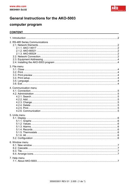
General Instructions for the AKO-5003 computer program
General Instructions for the AKO-5003 computer program
General Instructions for the AKO-5003 computer program
Create successful ePaper yourself
Turn your PDF publications into a flip-book with our unique Google optimized e-Paper software.
www.ako.com<br />
<strong>5003</strong>H001 Ed.02<br />
<strong>General</strong> <strong>Instructions</strong> <strong>for</strong> <strong>the</strong> <strong>AKO</strong>-<strong>5003</strong><br />
<strong>computer</strong> <strong>program</strong><br />
CONTENT<br />
1. Introduction .................................................................................................................................2<br />
2. RS-485 Series Communications<br />
2.1. Network Elements................................................................................................................2<br />
2.1.1. <strong>AKO</strong>-14917 ..................................................................................................................2<br />
2.1.2. <strong>AKO</strong>-80021 ..................................................................................................................2<br />
2.1.3. <strong>AKO</strong>-80024 ..................................................................................................................2<br />
2.2. Network Connection.............................................................................................................2<br />
2.3. Equipment Addressing.........................................................................................................4<br />
2.4. Installing <strong>the</strong> <strong>AKO</strong>-<strong>5003</strong> <strong>program</strong> .........................................................................................4<br />
3. File menu<br />
3.1. Close ...................................................................................................................................4<br />
3.2. Print .....................................................................................................................................4<br />
3.3. Print preview ........................................................................................................................4<br />
3.4. Print setup............................................................................................................................4<br />
3.5. Language.............................................................................................................................4<br />
3.6. Exit.......................................................................................................................................4<br />
4. Communication menu<br />
4.1. Connection...........................................................................................................................5<br />
4.2. Administration ......................................................................................................................5<br />
4.2.1. Search..........................................................................................................................5<br />
4.2.2. Add...............................................................................................................................5<br />
4.2.3. Change.........................................................................................................................5<br />
4.2.4. Delete...........................................................................................................................5<br />
4.2.5. Print..............................................................................................................................5<br />
4.2.6. Communication ............................................................................................................5<br />
5. Units menu<br />
5.1. Display.................................................................................................................................6<br />
5.1.1. Graphs .........................................................................................................................6<br />
5.1.2. Values ..........................................................................................................................6<br />
5.1.3. Alarms..........................................................................................................................6<br />
5.1.4. Records........................................................................................................................6<br />
5.1.5. Thermostats .................................................................................................................6<br />
5.1.6. All .................................................................................................................................6<br />
5.2. Configuration .......................................................................................................................6<br />
6. Window menu<br />
6.1. New window.........................................................................................................................7<br />
6.2. Cascade...............................................................................................................................7<br />
6.3. Tile.......................................................................................................................................7<br />
6.4. Arrange icons.......................................................................................................................7<br />
7. Help menu<br />
7.1. About <strong>AKO</strong>-<strong>5003</strong>..................................................................................................................7<br />
35<strong>5003</strong>001 REV.01 2.005 (1 de 7)
www.ako.com<br />
<strong>5003</strong>H001 Ed.02<br />
1. Introduction<br />
<strong>AKO</strong>-<strong>5003</strong> is a monitoring <strong>program</strong> <strong>for</strong> <strong>AKO</strong> controllers with communications and recorder connector <strong>AKO</strong>-15715,<br />
<strong>AKO</strong>-15716, <strong>AKO</strong>-15720 and <strong>AKO</strong>-15722.<br />
This <strong>program</strong> includes <strong>the</strong> following functions:<br />
- Status display and recording of <strong>the</strong> devices connected to <strong>the</strong> RS485 network.<br />
- The printing of graphs showing <strong>the</strong> equipment temperature values.<br />
- It facilitates control parameter modification <strong>for</strong> <strong>the</strong> various pieces of equipment.<br />
These instructions <strong>for</strong>m guidelines <strong>for</strong> <strong>the</strong> following processes:<br />
- Installing <strong>the</strong> RS485 series communications connection.<br />
- Installing <strong>the</strong> <strong>AKO</strong>-<strong>5003</strong> PC <strong>program</strong>.<br />
- Using <strong>the</strong> <strong>AKO</strong>-<strong>5003</strong> <strong>program</strong>.<br />
2. RS-485 Series Communications<br />
The communications system is based on an RS485 network employing <strong>the</strong> MODBUS protocol.<br />
2.1. Network Elements<br />
The following elements are required to connect <strong>the</strong> various devices to <strong>the</strong> <strong>computer</strong>.<br />
2.1.1. <strong>AKO</strong>-14917 CMOS/RS485 converter module<br />
This module is required to connect <strong>the</strong> temperature controllers to <strong>the</strong> RS485 network. Each module can handle a<br />
single controller, which means that a controller will be needed <strong>for</strong> each controller to be connected to <strong>the</strong> RS485<br />
network.<br />
The temperature recorders may be connected directly to <strong>the</strong> RS485 network.<br />
2.1.2. <strong>AKO</strong>-80021 RS232/RS485 converter module<br />
This converter is required to connect <strong>the</strong> RS485 network to <strong>the</strong> <strong>computer</strong> serial port. This module incorporates<br />
automatic receive/transmit mode switching and a 9600-baud transmission speed.<br />
A maximum of 31 devices may be directly connected to <strong>the</strong> converter.<br />
2.1.3. <strong>AKO</strong>-80024 repeater module<br />
If more than 31 devices are to be connected, <strong>the</strong>n repeater modules will be required. <strong>AKO</strong> has a repeater available<br />
<strong>for</strong> this purpose, <strong>the</strong> <strong>AKO</strong>-80024, which can be connected to a maximum of 31 devices.<br />
2.2. Network Connection<br />
The series cable supplied with <strong>the</strong> <strong>AKO</strong>-80021 equipment should be used to connect <strong>the</strong> converter module to <strong>the</strong><br />
<strong>computer</strong>’s serial port (if necessary, 9-25-pin adapter should be employed, which is not supplied with <strong>the</strong><br />
equipment).<br />
The connection between <strong>the</strong> <strong>AKO</strong>-80021 converter and <strong>the</strong> devices connected to <strong>the</strong> RS485 network (<strong>AKO</strong>-14917,<br />
<strong>AKO</strong>-80024, <strong>AKO</strong>-15715, <strong>AKO</strong>-15716, <strong>AKO</strong>-15720 or <strong>AKO</strong>-15722), is made with cable containing two twisted pairs<br />
and screen, FTP 2x2x0,25, in accordance with <strong>the</strong> drawings.<br />
Each piece of equipment should be connected with <strong>the</strong> three RS485 network cables as shown in <strong>the</strong> figure, with<br />
<strong>the</strong> screen connected to earth.<br />
Precautions:<br />
- The cable polarity, Tx+ and Tx- must be respected.<br />
- Maximum RS485 network length cannot exceed 1,200 metres.<br />
- The network cables must never be installed in conduit toge<strong>the</strong>r with mains power or power supply wiring.<br />
- When <strong>the</strong> distance is very long, a 120Ω ¼W resistor (not supplied by <strong>AKO</strong>) should be installed between<br />
contacts Tx+ and Tx- on <strong>the</strong> unit fur<strong>the</strong>st away from <strong>the</strong> RS232/RS485 converter module, just as shown in <strong>the</strong><br />
figure:<br />
35<strong>5003</strong>001 REV.01 2.005 (2 de 7)
www.ako.com<br />
<strong>5003</strong>H001 Ed.02<br />
35<strong>5003</strong>001 REV.01 2.005 (3 de 7)
www.ako.com<br />
<strong>5003</strong>H001 Ed.02<br />
2.3. Equipment Addressing<br />
All devices connected to <strong>the</strong> RS485 network must have an identifying address. This is a number, which is unique<br />
throughout <strong>the</strong> entire network, so that <strong>the</strong> device can be recognised by <strong>the</strong> <strong>AKO</strong>-<strong>5003</strong>. The RS485 network has an<br />
address range of 1 to 247.<br />
The <strong>AKO</strong> controllers with communications connectors, have an address range from 1 to 126.<br />
The P5 parameter stores this number, which by default, contains <strong>the</strong> value 0.<br />
For in<strong>for</strong>mation on how to <strong>program</strong> <strong>the</strong> controller addresses, read <strong>the</strong> instructions that came with <strong>the</strong> equipment,<br />
data sheet 1400H161.<br />
Recorders <strong>AKO</strong>-15715, <strong>AKO</strong>-15716, <strong>AKO</strong>-15720 and <strong>AKO</strong>-15722, have a range of addresses from 1 to 247.<br />
For in<strong>for</strong>mation on how to <strong>program</strong> <strong>the</strong> recorders read <strong>the</strong> instructions that came with <strong>the</strong> equipment, data sheet<br />
1572H101.<br />
2.4. Installing <strong>the</strong> <strong>AKO</strong>-<strong>5003</strong> <strong>program</strong><br />
The minimum system requirements are:<br />
- WINDOWS 98, Millennium, 2000 or XP<br />
- 32 Mbytes RAM<br />
- Approximately 6 Mbytes of hard disk space <strong>for</strong> each connected device<br />
- CD-ROM drive<br />
- Mouse<br />
- VGA video card and monitor. Recommended resolution: 800x600<br />
- RS-232 serial port<br />
The <strong>AKO</strong>-<strong>5003</strong> <strong>program</strong> is distributed on CD-ROM, with file name “31<strong>5003</strong>000.zip.”<br />
To install, unzip this file to a temporary directory. This operation will create five new files:<br />
“Setup<strong>5003</strong>.msi”<br />
“InstMsiW.exe”<br />
“Setup.exe”<br />
“Setup.ini”<br />
“InstMsiA.exe”<br />
Run “Setup.exe” and follow <strong>the</strong> steps displayed by <strong>the</strong> installation <strong>program</strong>.<br />
Once <strong>the</strong> process has been completed, <strong>the</strong> <strong>computer</strong> must be re-started.<br />
3. File menu<br />
The File menu contains <strong>the</strong> following options:<br />
3.1. Close<br />
Close <strong>the</strong> document without exiting <strong>the</strong> application.<br />
3.2. Print<br />
Print <strong>the</strong> current graph.<br />
3.3. Print preview<br />
Display <strong>the</strong> document layout be<strong>for</strong>e printing it.<br />
3.4. Print setup<br />
Set-up page orientation, sheet source and size.<br />
3.5. Language<br />
Lists <strong>the</strong> various languages in which <strong>the</strong> <strong>program</strong> may be used.<br />
English, French, German or Spanish may be selected in this <strong>program</strong>.<br />
3.6. Exit<br />
Close <strong>the</strong> application.<br />
35<strong>5003</strong>001 REV.01 2.005 (4 de 7)
www.ako.com<br />
<strong>5003</strong>H001 Ed.02<br />
4. Communication menu<br />
The Communication menu contains <strong>the</strong> following options:<br />
4.1. Connection<br />
The <strong>program</strong> displays a list of <strong>the</strong> serial ports, COM1, COM2, COM3 and COM4, but only <strong>the</strong> ones that are actually<br />
available may be selected. The communications port connected to <strong>the</strong> <strong>AKO</strong>-80021 converter should be selected.<br />
4.2. Administration<br />
On selection of this option, <strong>the</strong> <strong>program</strong> will display a list of all <strong>the</strong> devices connected to <strong>the</strong> network, toge<strong>the</strong>r with<br />
<strong>the</strong>ir status.<br />
This section includes <strong>the</strong> following options:<br />
4.2.1. Search<br />
This section is used to search <strong>for</strong> new devices connected to <strong>the</strong> network, specifying and address range and<br />
limiting, where specified, <strong>the</strong> number of devices to be searched <strong>for</strong>.<br />
If <strong>the</strong> number of devices to be searched <strong>for</strong> has been specified and <strong>the</strong> devices found do not coincide, <strong>the</strong>n <strong>the</strong><br />
<strong>program</strong> will display a message requesting that <strong>the</strong> search operation be repeated.<br />
Once <strong>the</strong> search operation has been completed, <strong>the</strong> <strong>program</strong> will request that fields identifying a device, such as<br />
device reference and description be completed.<br />
4.2.2. Add<br />
Permits manual registration of a device connected to <strong>the</strong> network.<br />
The <strong>program</strong> will request device address, reference and description.<br />
If <strong>the</strong> <strong>program</strong> is unable to find <strong>the</strong> indicated device, <strong>the</strong>n it will display an error message.<br />
4.2.3. Change<br />
Permits modification of <strong>the</strong> selected device’s reference and description.<br />
4.2.4. Delete<br />
This option will delete <strong>the</strong> selected device from <strong>the</strong> equipment list.<br />
When <strong>the</strong> command is executed, it will delete all in<strong>for</strong>mation on <strong>the</strong> <strong>computer</strong> which refers to this device.<br />
4.2.5. Print<br />
Prints <strong>the</strong> list of devices connected to <strong>the</strong> network.<br />
4.2.6. Communication<br />
This option displays <strong>the</strong> communications incidents log.<br />
This log displays <strong>the</strong> device number and description, <strong>the</strong> type of error that occurred, toge<strong>the</strong>r with this error’s start<br />
and end times.<br />
35<strong>5003</strong>001 REV.01 2.005 (5 de 7)
www.ako.com<br />
<strong>5003</strong>H001 Ed.02<br />
5. Units menu:<br />
The Equipment menu contains <strong>the</strong> following options:<br />
5.1. Display<br />
When selected, this option displays a list of devices connected to <strong>the</strong> network, toge<strong>the</strong>r with current status.<br />
The available options are as follows:<br />
5.1.1. Graphs<br />
Permits <strong>the</strong> readings stored on <strong>the</strong> <strong>computer</strong> <strong>for</strong> one of <strong>the</strong> selected devices sensors to be displayed in a graphic<br />
manner.<br />
When executed, this <strong>program</strong> will request <strong>the</strong> period of time to be displayed, (start and end dates), toge<strong>the</strong>r with<br />
<strong>the</strong> entry <strong>for</strong> which <strong>the</strong> data is to be read.<br />
5.1.2. Values<br />
Displays a list of <strong>the</strong> readings, stored on <strong>the</strong> <strong>computer</strong>, of all <strong>the</strong> selected device’s sensors.<br />
When executed, this <strong>program</strong> will request <strong>the</strong> period of time to be displayed.<br />
5.1.3. Alarms<br />
Permits display of <strong>the</strong> selected device’s alarm log in list <strong>for</strong>m.<br />
When executed, this <strong>program</strong> will request <strong>the</strong> period of time to be displayed.<br />
5.1.4. Records<br />
This option is only available <strong>for</strong> <strong>the</strong> <strong>AKO</strong>-15715, <strong>AKO</strong>-15716, <strong>AKO</strong>-15720 and <strong>AKO</strong>-15722 recorders.<br />
It will display <strong>the</strong> readings held in <strong>the</strong> device’s memory in a graphical fashion.<br />
When executed, this <strong>program</strong> will request <strong>the</strong> record to be displayed, toge<strong>the</strong>r with <strong>the</strong> record number.<br />
5.1.5. Thermostats<br />
This option provides a chart display of <strong>the</strong> selected temperature controller’s current status.<br />
5.1.6. All<br />
The option produces a list display of <strong>the</strong> readings and status <strong>for</strong> all devices connected to <strong>the</strong> network.<br />
5.2. Configuration<br />
This uses dialogue boxes to establish <strong>the</strong> parameters <strong>for</strong> all devices.<br />
These parameters may be stored on <strong>the</strong> disk <strong>for</strong> later use with o<strong>the</strong>r devices.<br />
35<strong>5003</strong>001 REV.01 2.005 (6 de 7)
www.ako.com<br />
<strong>5003</strong>H001 Ed.02<br />
6. Window menu<br />
This contains <strong>the</strong> following options:<br />
6.1. New window<br />
A new window is opened with <strong>the</strong> same contents as <strong>the</strong> previously active window, so that different sections of a file<br />
may be displayed at <strong>the</strong> same time.<br />
6.2. Cascade<br />
The various windows are displayed on <strong>the</strong> screen one on top of <strong>the</strong> o<strong>the</strong>r.<br />
6.3. Tile<br />
The various windows are displayed in a mosaic fashion so that all are immediately identified.<br />
6.4. Arrange icons<br />
This command should be used to organise <strong>the</strong> icons <strong>for</strong> <strong>the</strong> minimised windows at <strong>the</strong> bottom of <strong>the</strong> main window.<br />
If <strong>the</strong>re is a document window open at <strong>the</strong> bottom of <strong>the</strong> main window, some or even all <strong>the</strong> icons might not be<br />
displayed because <strong>the</strong>y will be covered by this document window.<br />
7. Help menu<br />
7.1. About <strong>AKO</strong>-<strong>5003</strong><br />
Displays <strong>the</strong> version number <strong>for</strong> <strong>the</strong> de <strong>AKO</strong>-<strong>5003</strong> <strong>program</strong>.<br />
<strong>AKO</strong> Electromecánica, S.A.L. Av. Roquetes, 30-38 08812 Sant Pere de Ribes (Barcelona) Tel. (34) 938 142 700<br />
Nos reservamos el derecho de suministrar materiales que pudieran diferir levemente de los descritos en nuestras Hojas Técnicas.<br />
In<strong>for</strong>mación actualizada en nuestra web: www.ako.com<br />
35<strong>5003</strong>001 REV.01 2.005 (7 de 7)


