ACO Haustechnik
ACO Haustechnik
ACO Haustechnik

You also want an ePaper? Increase the reach of your titles
YUMPU automatically turns print PDFs into web optimized ePapers that Google loves.
Installation and operating instructions<br />
Service line<br />
Tel. +49 (0) 36965 819–0<br />
Fax +49 (0) 36965 819–361<br />
1<br />
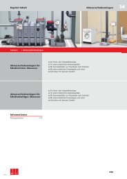
<strong>ACO</strong> H a u s t e c h n i k<br />
0150.16.70<br />
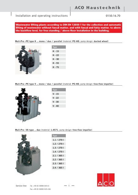
Wastewater lifting plants according to DIN EN 12050-1 for the collection and automatic<br />
lifting of wastewater without faecal matter, and with faecal and fatty matter, to above<br />
the backflow level, for free-standing / above-floor installation in the building.<br />
Muli-Pro -PE type K .. mono / duo / parallel (material: PE-HD, pump design: ducted wheel)<br />
Type<br />
K - 15<br />
K - 22<br />
K - 30<br />
K - 55<br />
K - 75<br />
Muli-Pro -PE type V .. mono / duo / parallel (material: PE-HD, pump design: free-flow impeller)<br />
Type<br />
V - 15<br />
V - 22<br />
V - 30<br />
V - 40<br />
Muli-Pro -VA type .. duo (material: 1.4571, pump design: free-flow impeller)<br />
Type<br />
1.1 / 270 l<br />
1.2 / 270 l<br />
1.3 / 270 l<br />
1.4 / 270 l<br />
2.1 / 365 l<br />
2.2 / 365 l<br />
2.3 / 365 l<br />
2.4 / 365 l
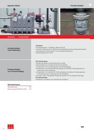
Data on the type plate |<br />
Muli-Pro-...<br />
Note | These operating instructions contain basic instructions which<br />
have to be observed during installation, operation and maintenance. It<br />
is therefore essential that the mechanic and responsible qualified staff/<br />
operator read these instructions prior to installation and operation, and<br />
that they are always available where the machine is installed.<br />
Tel. +49 (0) 36965 819–0<br />
Fax +49 (0) 36965 819–361<br />
<strong>ACO</strong> Passavant GmbH<br />
Im Gewerbepark 11c<br />
36457 Stadtlengsfeld, Germany<br />
Telephone 49-(0) 36965 819 - 0<br />
Fax 49-(0) 36965 819 - 361<br />
Wastewater lifting plant DIN EN 12050 - 1<br />
External monitoring certification LGA - Würzburg No. 0120022<br />
Year of manufacture<br />
Article number<br />
Serial number<br />
2<br />
Data<br />
0150.16.70<br />
Please copy and enter the data<br />
from the original type plate on<br />
the system.
Service line<br />
Tel. +49 (0) 36965 819–0<br />
Fax +49 (0) 36965 819–361<br />
3<br />
<strong>ACO</strong> H a u s t e c h n i k<br />
0150.16.70<br />
Content<br />
Chapter Page<br />
1. Product identification<br />
1.1 Manufacturer ........................................................................................................................... 5<br />
1.2 Supplier .................................................................................................................................. 5<br />
1.3 Electrician ............................................................................................................................... 5<br />
1.4 Address ... .............................................................................................................................. 5<br />
1.5 Fitter ...................................................................................................................................... 5<br />
1.6 Plant fitter ............................................................................................................................... 5<br />
1.7 Address ... .............................................................................................................................. 5<br />
1.8 EU conformity declaration ........................................................................................................ 6<br />
1.9 Installation of wastewater lifting plants, where and why .............................................................. 7<br />
1.10 Description: design / type ........................................................................................................ 9<br />
1.11 Description: mono / duo / parallel designs .............................................................................. 10<br />
1.12 Areas of application ............................................................................................................... 10<br />
1.13 Technical data, dimensions, performance diagrams, characteristic data .................................... 11<br />
2. Scope<br />
2.1 Applicability of the installation and operating instructions .......................................................... 18<br />
2.2 General information ............................................................................................................... 18<br />
3. Notes<br />
3.1 Explanation of symbols and notes ........................................................................................... 19<br />
3.2 Safety notices ....................................................................................................................... 20<br />
3.3 Directives and standards ........................................................................................................ 22<br />
4. Product description<br />
4.1 Components of Muli-Pro-PE design .......................................................................................... 27<br />
4.2 Components of Muli-Pro-VA design .......................................................................................... 28<br />
4.3 Switch box design types ........................................................................................................ 29<br />
4.4 Function (except for type K-55 and K-75) ................................................................................. 32<br />
4.5 Function Type K-55 and K-75 .................................................................................................. 33<br />
4.6 Installation recommendations ................................................................................................. 34<br />
4.7 Information on energy supply .................................................................................................. 35<br />
4.8 Information on potential-free contact – collective fault signal / operating signal .......................... 35<br />
4.9 Environmental conditions ........................................................................................................ 35<br />
4.10 Accessories .......................................................................................................................... 36<br />
5. Preparation of the product for use<br />
5.1 Transport, delivery and storage .............................................................................................. 38<br />
5.2 Fitter work for the mono and duo designs................................................................................ 39<br />
5.3 Fitter work for the parallel design ............................................................................................ 44<br />
5.4 Electrical work ...................................................................................................................... 46
6. Operating instructions<br />
Tel. +49 (0) 36965 819–0<br />
Fax +49 (0) 36965 819–361<br />
4<br />
0150.16.70<br />
6.1 Commissioning ...................................................................................................................... 49<br />
6.2 Explanation of the operating and indicating elements of the plug-ready switch boxes .................. 50<br />
6.3 Explanation of the operating and indicating elements of the connection-ready switch boxes ......... 52<br />
6.4 Schematic representation of the pneumatic level switching (with air bubbling) ............................. 54<br />
6.5 Test run process description (in this example: duo design with inlet from above) ......................... 56<br />
6.6 Operation .............................................................................................................................. 60<br />
6.7 Faults and their remedies ....................................................................................................... 61<br />
7. Servicing<br />
7.1 Instructions for maintenance and repair work ........................................................................... 62<br />
7.2 Regular inspections ............................................................................................................... 62<br />
7.3 Regular maintenance and repair work ...................................................................................... 63<br />
8. Repair<br />
9. Decommissioning<br />
9.1 Disassembly ......................................................................................................................... 64<br />
9.2 Disposal ............................................................................................................................... 64<br />
9.3 Decommissioning for a limited period of time .......................................................................... 64<br />
10. Stocking of spare parts and after-sales services<br />
10.1 Maintenance and wearing parts .............................................................................................. 65<br />
10.2 Order data ............................................................................................................................ 65<br />
11. Appendix<br />
11.1 Connection diagram for plug-ready switch box design -mono- up to 5 kW .................... 66<br />
11.2 Connection diagram for plug-ready switch box design -duo- up to 5 kW .................... 66<br />
11.3 Connection diagram for connection-ready switch box design -mono- 5.5 kW and higher .......... 67<br />
11.4 Connection diagram for connection-ready switch box design -duo- 5.5 kW and higher ......... 67
1. Product identification<br />
1.1 Manufacturer<br />
<strong>ACO</strong> Passavant GmbH<br />
Im Gewerbepark 11c<br />
36457 Stadtlengsfeld, Germany<br />
Telephone 49-(0) 36965 819 - 0<br />
Fax 49-(0) 36965 819 - 36<br />
1.2 Supplier<br />
Telephone<br />
Fax<br />
1.4 Electrician<br />
Telephone<br />
Fax<br />
1.6 Address ...<br />
Telephone<br />
Fax<br />
Service line<br />
Tel. +49 (0) 36965 819–0<br />
Fax +49 (0) 36965 819–361<br />
5<br />
<strong>ACO</strong> H a u s t e c h n i k<br />
After-Sales Service Department<br />
<strong>ACO</strong> <strong>Haustechnik</strong> GmbH<br />
Im Gewerbepark 11c<br />
36457 Stadtlengsfeld, Germany<br />
0150.16.70<br />
Service - Telephone 49-(0) 36965 819 - 444<br />
Service - Fax 49-(0) 36965 819 - 367<br />
E-mail service@aco-online.de<br />
1.3 Fitter<br />
Telephone<br />
Fax<br />
1.5 Plant fitter<br />
Telephone<br />
Fax<br />
1.7 Address ...<br />
Telephone<br />
Fax
1.8 EU conformity declaration<br />
EG - Konformitätserklärung<br />
Hiermit erklärt der Hersteller<br />
<strong>ACO</strong> Passavant GmbH<br />
Ulsterstraße 3<br />
36269 Philippsthal<br />
dass die Maschinenanlagen<br />
Muli Pro - PE / VA mono, duo und parallel<br />
konform sind mit der Bestimmung der<br />
EG-RL 2006/42/EG (Maschinenrichtlinie).<br />
Maschinen der Anlage sind konform mit weiteren Richtlinien:<br />
EG-RL 2006/95/EG (Niederspannungsrichtlinie).<br />
Folgende harmonisierte Normen wurden angewandt:<br />
DIN EN 12050-1 (Ausgabe 2001-05)<br />
Folgende gemeldete Stelle wurde eingeschaltet:<br />
LGA-Würzburg, Kenn-Nr. 0120022<br />
für:<br />
Fremdüberwachung<br />
Zuständiger Dokumentenbeauftragter:<br />
Herr Marco Eulenstein<br />
<strong>ACO</strong> <strong>Haustechnik</strong> GmbH<br />
Im Gewerbepark 11c<br />
36457 Stadtlengsfeld<br />
Philippstahl, 01.11.2009<br />
Unterschrift<br />
Tel. +49 (0) 36965 819–0<br />
Fax +49 (0) 36965 819–361<br />
Ralf Sand<br />
(Geschäftsführung, <strong>ACO</strong> Passavant GmbH)<br />
6<br />
0150.16.70
1.9 Installation of wastewater lifting plants, where and why<br />
General aspects<br />
Building regulations | According to state building regulations, buildings<br />
and other structures may only be erected if the elimination of wastewater is<br />
properly and permanently ensured. Property grounds on which wastewater<br />
arises must be connected to the public sewer system, if they are ready<br />
for operation. It is this requirement, i.e., the direct connection of a<br />
property's drainage system to the public sewer system, that gives rise<br />
to the problem of backflow in this area. The frequency of such backflows<br />
depends on the type of sewer system used, i.e. whether it is a separate or<br />
combined system. In separate sewer systems, dirty water and rainwater<br />
are transported in separate pipe systems. This makes it less common for<br />
backflows to occur in dirty water sewers due to factors such as illegal<br />
introduction of waste, pipeline blockages and operationally necessary<br />
sewer measures; however, such backflows can never be entirely prevented.<br />
For economic reasons and to ensure the self-cleaning capability of the<br />
system, the current practice is to dimension drainage systems for a<br />
moderate level of rainfall. However, it must be expected that heavy rainfalls<br />
exceeding the amount used as the basis for calculation will occur. This<br />
means that a drainage system overload could occur at any time.<br />
Sewer backup | The physical effects of a sewer backup are based on<br />
the law of communicating tubes. If a backup occurs, the wastewater finds<br />
its way through these pipes into the property drainage system because the<br />
pipe systems of the property drainage system are directly connected to<br />
the public sewer system. The water rises to the same level as the water in<br />
the public sewer. This means that wastewater will continue to escape from<br />
all unprotected openings, such as floor drains, toilets, etc., until the water<br />
levels have reached equilibrium (Fig. 1-1).<br />
Backflow level | This results in a specific elevation or level below which<br />
special measures must be implemented as part of the property drainage<br />
system to protect against the risk of backflows on the property. This level<br />
is referred to as the backflow level. The pertinent backflow level is defined<br />
by the local authorities in the town by-laws. If no such definition exists, DIN<br />
EN 12056-4 and DIN 1986-100 defines the backflow level as the level of<br />
the top edge of the street above the location where the property drainage<br />
line connects to the public sewer system.<br />
Nevertheless, the backing up of water even above this level cannot be<br />
completely ruled out, for instance due to pipe blockages. If backed-up<br />
water penetrates within buildings into unprotected rooms, masonry walls<br />
and foundations can become saturated. This backed-up water can also<br />
cause water damage to furnishings. There may also be health risks due to<br />
infections. For these reasons, the risk and potential damage of backflowing<br />
wastewater must be kept as low as possible using preventive measures.<br />
According to town wastewater by-laws, the responsibility for these<br />
measures generally lies with the property owner. Property owners can hire<br />
suitable experts, such as qualified planners and fitters, to properly plan and<br />
execute such measures.<br />
Service line<br />
Tel. +49 (0) 36965 819–0<br />
Fax +49 (0) 36965 819–361<br />
7<br />
<strong>ACO</strong> H a u s t e c h n i k<br />
Figure 1-1:<br />
Sewer backflow<br />
0150.16.70
General aspects<br />
Protection against backflow | The greatest possible protection against<br />
backflow can be achieved with a wastewater lifting plant with a pressurised<br />
line that runs to above the backflow level (Fig. 1-2, 1-3).<br />
Backflow level<br />
Figure 1-2:<br />
Protection against backflow with an incline to the<br />
sewer using a wastewater lifting plant<br />
Regulations | DIN1986-100, “Drainage systems on private ground” and<br />
EN 12056 “Gravity drainage systems inside buildings” require that dirty<br />
water arising below the backflow level and precipitation water from surfaces<br />
below the backflow level be brought into the public sewer system in a<br />
manner than protects against backflows through the use of an automatic<br />
lifting plant.<br />
Drainage systems are planned according to the principle that “arising<br />
surface water must be diverted away from the building and not brought into<br />
the building.” Accordingly, surfaces exposed to rain must be drained by<br />
separate pump stations outside of the building.<br />
All drainage features situated above the backflow area must be drained<br />
with natural inclines (gravity principle); the wastewater from these drainage<br />
features may not be diverted through anti-flooding valves and may only be<br />
diverted through wastewater lifting plants in exceptional cases in which this<br />
is absolutely necessary (e.g. old building renovation).<br />
Tel. +49 (0) 36965 819–0<br />
Fax +49 (0) 36965 819–361<br />
8<br />
Backflow level<br />
0150.16.70<br />
Figure 1-3:<br />
Protection against backflow when the sewer is<br />
situated at a higher level than the drainage features
1.10 Description: design / type<br />
Design ...<br />
-PE | Polyethylene (PE-HD), rotated, collecting container.<br />
-VA | Stainless steel (1.4571), welded, collecting container.<br />
Type ...<br />
-K | Pump design, hydraulic component with ducted wheel (particle size<br />
70 mm or 100 mm with type K-75).<br />
The ducted wheel is suitable for pumping dirty water containing faecal<br />
matter as well as for pumping wastewater with firm, short, fibrous solids<br />
and thick matter, sludge and organic materials.<br />
Figure 1-4:<br />
3D ducted wheel<br />
-V | Pump design, hydraulic component with free-flow impeller (particle<br />
size 80 mm).<br />
A large open space in the pump housing (a sphere passage) allows the<br />
liquid to easily flow through the suction opening into the pump chamber<br />
and allows solid and long-fibred thick matter, such as long sanitary towels,<br />
textiles, etc. to pass through the pump housing without difficulty.<br />
Another advantage: Since free-flow pumps do not have a choke gap<br />
between the impeller and the pump housing, this design offers great<br />
operational reliability for applications with very long periods of inactivity.<br />
This prevents the impeller from rusting into place, which would result in<br />
blocking of the pump.<br />
Figure 1-6:<br />
3D free-flow wheel<br />
Service line<br />
Tel. +49 (0) 36965 819–0<br />
Fax +49 (0) 36965 819–361<br />
Figure 1-5:<br />
Ducted wheel cross-section<br />
Figure 1-7:<br />
3D pump cross section<br />
9<br />
<strong>ACO</strong> H a u s t e c h n i k<br />
0150.16.70
1.11 Description: mono / duo / parallel designs<br />
mono design<br />
Wastewater lifting plants with one pump = -mono- design.<br />
Used in places where the wastewater flow may be interrupted or in rooms<br />
subject to less frequent use.<br />
Figure 1-8:<br />
-mono- wastewater lifting plant<br />
duo design<br />
Wastewater lifting plants with two pumps = -duo- design.<br />
Used in places where the wastewater flow may not be interrupted.<br />
The two pumps operate in alternation or together in event of a heavy load.<br />
parallel design<br />
Wastewater lifting plants with two collecting containers and 2 pumps =<br />
-parallel- design.<br />
Used in places where the wastewater flow may not be interrupted and in<br />
buildings with large volumes of wastewater, typically for commercial and<br />
industrial applications.<br />
The two pumps operate in alternation or<br />
together in event of a heavy load.<br />
1.12 Areas of application<br />
matter<br />
faecal with<br />
<br />
water<br />
= suitable<br />
- = not suitable Dirty<br />
Tel. +49 (0) 36965 819–0<br />
Fax +49 (0) 36965 819–361<br />
Pumping medium<br />
Wastewater with firm and short,<br />
fibrous solids and thick matter,<br />
sludge and organic materials<br />
10<br />
Wastewater with firm and long,<br />
fibrous thick matter<br />
Figure 1-9:<br />
-duo- wastewater lifting plant<br />
Figure 1-10:<br />
-parallel- wastewater lifting plant<br />
Wastewater containing grease<br />
For large volumes of wastewater<br />
For long pressure lines and<br />
greater height differences<br />
0150.16.70<br />
Type K mono - -<br />
Type K duo - <br />
Type V mono -<br />
Type V duo <br />
Type 1.1- 2.4 duo <br />
Type K parallel - <br />
Type V parallel <br />
Wastewater flow may be<br />
interrupted<br />
Wastewater flow may not be<br />
interrupted
Service line<br />
Tel. +49 (0) 36965 819–0<br />
Fax +49 (0) 36965 819–361<br />
11<br />
<strong>ACO</strong> H a u s t e c h n i k<br />
1.13 Technical data, dimensions, performance diagrams, characteristic data<br />
Muli-Pro-PE K- (15, 22, 30, 55, 75) mono<br />
-Product information |<br />
Wastewater lifting plants acc. to DIN EN 12050-1<br />
For collection and automatic lifting of greasy<br />
wastewater with or without faecal matter to above<br />
the backflow level<br />
For free-standing / above-floor installation in<br />
buildings<br />
Polyethylene collecting container<br />
Length 1500 x 780 x 1035 mm / LxWxH<br />
Drain screw and connection for hand diaphragm<br />
pump R 1 1/2<br />
Fastening set for anchoring against lifting<br />
forces<br />
Total container volume: 515 litres,<br />
Useful container volume depending on inlet<br />
height<br />
1x inlet DN 150 inlet height 600 mm = 180 l<br />
2x inlet DN 150 inlet height 750 mm = 250 l<br />
1x inlet DN 150 inlet height 800 mm = 275 l<br />
-Dimensions |<br />
-Characteristic data |<br />
1x inlet DN 150 from above 1015 mm = 275 l<br />
1x inspection opening, width 320 mm<br />
Connection for ventilation line DN 100<br />
Pipe connections suitable for plastic pipes or<br />
coated, grey cast iron plain end pipes<br />
Pressure line with connection for pipe outer Ø 108<br />
- 114 mm<br />
Special check valve DN 80 (on K-75 DN 100)<br />
with air intake mechanism<br />
Shut-off valve DN 80<br />
(on K-75 DN 100)<br />
Special fastener for connection to the pressure<br />
line<br />
Pump unit<br />
Motor 400 V / 50 Hz,<br />
Connection cable 7 m long<br />
Protection type IP 68<br />
Shaft seal and floating ring seal<br />
-Performance diagram |<br />
Type Motor power in kW Rated current Weight Article<br />
number<br />
P 1 P 2 A at 400 V approx. / in kg<br />
K - 15 2.01 1.5 3.6 225 0175.13.00<br />
K - 22 2.94 2.2 5.2 250 0175.13.01<br />
K - 30 3.87 3.0 6.6 315 0175.13.02<br />
K - 55 6.71 5.5 11.6 335 0175.13.03<br />
K - 75 8.97 7.5 15.5 335 0175.13.04<br />
0150.16.70<br />
Ducted wheel with 70 mm particle size<br />
(on K-75 100 mm)<br />
Pneumatic level switch with pitot tube and<br />
pneumatic control line (7 m long)<br />
Compact compressor for bubbling air<br />
Switching and warning device<br />
Protection type IP 54<br />
Plug-ready, with 1.5 m cable and CEE plug<br />
(on K-15 up to 30),<br />
dimensions 250 x 200 x 100 mm / WxHxD<br />
Connection-ready, cable provided by customer<br />
(on K-55 and 75),<br />
dimensions 380 x 600 x 210 mm / WxHxD<br />
With potential-free collective fault and operating<br />
signal
Muli-Pro-PE K- (15, 22, 30, 55, 75) duo<br />
-Product information |<br />
Wastewater lifting plants acc. to DIN EN 12050-1<br />
For collection and automatic lifting of greasy<br />
wastewater with or without faecal matter to above<br />
the backflow level<br />
For free-standing / above-floor installation in<br />
buildings<br />
Polyethylene collecting container<br />
Length 1500 x 780 x 1035 mm / LxWxH<br />
Drain screw and connection for hand diaphragm<br />
pump R 1 1/2<br />
Fastening set for anchoring against lifting<br />
forces<br />
Total container volume: 515 litres,<br />
Useful container volume depending on inlet<br />
height<br />
1x inlet DN 150 inlet height 600 mm = 160 l<br />
2x inlet DN 150 inlet height 750 mm = 230 l<br />
1x inlet DN 150 inlet height 800 mm = 250 l<br />
-Dimensions |<br />
-Characteristic data |<br />
Type Motor power in kW Rated current Weight Article<br />
number<br />
P 1 P 2 A at 400 V approx. / in kg<br />
K - 15 2.01 1.5 3.6 315 0175.13.17<br />
K - 22 2.94 2.2 5.2 325 0175.13.18<br />
K - 30 3.87 3.0 6.6 420 0175.13.19<br />
K - 55 6.71 5.5 11.6 465 0175.13.20<br />
K - 75 8.97 7.5 15.5 510 0175.13.21<br />
Tel. +49 (0) 36965 819–0<br />
Fax +49 (0) 36965 819–361<br />
1x inlet DN 150 from above 1015 mm = 250 l<br />
1x inspection opening, width 320 mm<br />
Connection for ventilation line DN 100<br />
Pipe connections suitable for plastic pipes or<br />
coated, grey cast iron plain end pipes<br />
Pressure line with connection for<br />
pipe outer Ø 108 - 114 mm<br />
2x special check valve DN 80 (on K-75 DN 100)<br />
with air intake mechanism<br />
2x shutoff valve DN 80<br />
(on K-75 DN 100)<br />
Y-pipe<br />
Special fastener for<br />
connection to the pressure line<br />
2 pump units<br />
Motor 400 V / 50 Hz,<br />
Connection cable 7 m long<br />
Protection type IP 68<br />
-Performance diagram |<br />
12<br />
0150.16.70<br />
Shaft seal and floating ring seal<br />
Ducted wheel with 70 mm particle size (on K-75<br />
100 mm)<br />
Pneumatic level switch with pitot tube and<br />
pneumatic control line (7 m long)<br />
Compact compressor for bubbling air<br />
Switching and warning device<br />
Protection type IP 54<br />
Plug-ready, with 1.5 m cable and CEE plug (on<br />
K-15 up to 30),<br />
dimensions 250 x 200 x 100 mm / WxHxD<br />
Connection-ready, cable provided by customer<br />
(on K-55 and 75),<br />
dimensions 380 x 600 x 210 mm / WxHxD<br />
With potential-free collective fault and operating<br />
signal
Muli-Pro-PE V- (15, 22, 30, 40) mono<br />
-Product information |<br />
Wastewater lifting plants acc. to DIN EN 12050-1<br />
For collection and automatic lifting of greasy<br />
wastewater with or without faecal matter to above<br />
the backflow level<br />
For free-standing / above-floor installation in<br />
buildings<br />
Polyethylene collecting container<br />
Length 1500 x 780 x 1035 mm / LxWxH<br />
Drain screw and connection for hand diaphragm<br />
pump R 1 1/2<br />
Fastening set for anchoring against lifting<br />
forces<br />
Total container volume: 515 litres, useful<br />
container volume depends on inlet height<br />
1x inlet DN 150 inlet height 600 mm = 180 l<br />
2x inlet DN 150 inlet height 750 mm = 250 l<br />
1x inlet DN 150 inlet height 800 mm = 275 l<br />
1x inlet DN 150 from above 1015 mm = 275 l<br />
-Dimensions |<br />
-Characteristic data |<br />
Type Motor power in kW Rated current Weight Article<br />
number<br />
P 1 P 2 A at 400 V approx. / in kg<br />
V - 15 2.01 1.5 4.1 180 0175.12.81<br />
V - 22 2.94 2.2 5.2 185 0175.12.82<br />
V - 30 3.87 3.0 6.6 195 0175.12.83<br />
V - 40 5.1 4.0 10.3 200 0175.12.84<br />
Service line<br />
Tel. +49 (0) 36965 819–0<br />
Fax +49 (0) 36965 819–361<br />
1x inspection opening, width 320 mm<br />
Connection for ventilation line DN 100<br />
Pipe connections suitable for plastic pipes or<br />
coated, grey cast iron plain end pipes<br />
Pressure line with connection for<br />
pipe outer Ø 108 - 114 mm<br />
Special check valve DN 80 with air intake<br />
mechanism<br />
Shut-off valve DN 80<br />
Special fastener for connection to the pressure<br />
line<br />
Pump units<br />
Motor 400 V / 50 Hz,<br />
Connection cable 7 m long<br />
Protection type IP 68<br />
Shaft seal and floating ring seal<br />
Non-blocking free-flow impeller with 80 mm<br />
particle size<br />
13<br />
<strong>ACO</strong> H a u s t e c h n i k<br />
-Performance diagram |<br />
0150.16.70<br />
Pneumatic level switch with pitot tube and<br />
pneumatic control line (7 m long)<br />
Compact compressor for bubbling air<br />
Switching and warning device<br />
Protection type IP 54<br />
Plug-ready, with 1.5 m cable and CEE plug,<br />
dimensions 250 x 200 x 100 mm / WxHxD<br />
With potential-free collective fault and operating<br />
signal
Muli-Pro-PE V- (15, 22, 30, 40) duo<br />
-Product information |<br />
Wastewater lifting plants acc. to DIN EN 12050-1<br />
For collection and automatic lifting of greasy<br />
wastewater with or without faecal matter to above<br />
the backflow level<br />
For free-standing / above-floor installation in<br />
buildings<br />
Polyethylene collecting container<br />
Length 1500 x 780 x 1035 mm / LxWxH<br />
Drain screw and connection for hand diaphragm<br />
pump R 1 1/2<br />
Fastening set for anchoring against lifting<br />
forces<br />
Total container volume: 515 litres,<br />
Useful container volume depending on inlet<br />
height<br />
1x inlet DN 150 inlet height 600 mm = 160 l<br />
2x inlet DN 150 inlet height 750 mm = 230 l<br />
1x inlet DN 150 inlet height 800 mm = 250 l<br />
-Dimensions |<br />
-Characteristic data |<br />
Type Motor power in kW Rated current Weight Article<br />
P 1 P 2 A at 400 V approx. / in kg<br />
number<br />
V - 15 2.01 1.5 4.1 210 0175.12.89<br />
V - 22 2.94 2.2 5.2 215 0175.12.90<br />
V - 30 3.87 3.0 6.6 225 0175.12.91<br />
V - 40 5.1 4.0 10.3 230 0175.12.92<br />
Tel. +49 (0) 36965 819–0<br />
Fax +49 (0) 36965 819–361<br />
1x inlet DN 150 from above 1015 mm = 250 l<br />
1x inspection opening, width 320 mm<br />
Connection for ventilation line DN 100<br />
Pipe connections suitable for plastic pipes or<br />
coated, grey cast iron plain end pipes<br />
Pressure line with connection for<br />
pipe outer Ø 108 - 114 mm<br />
2x special check valve DN 80 with air intake<br />
mechanism<br />
2x shutoff valve DN 80<br />
Y-pipe<br />
Special fastener for connection to the pressure<br />
line<br />
2 pump units<br />
Motor 400 V / 50 Hz,<br />
Connection cable 7 m long<br />
Protection type IP 68<br />
Shaft seal and floating ring seal<br />
14<br />
-Performance diagram |<br />
0150.16.70<br />
Non-blocking free-flow impeller with 80 mm<br />
particle size<br />
Pneumatic level switch with pitot tube and<br />
pneumatic control line (7 m long)<br />
Compact compressor for bubbling air<br />
Switching and warning device<br />
Protection type IP 54<br />
Plug-ready, with 1.5 m cable and CEE plug,<br />
dimensions 250 x 200 x 100 mm / WxHxD<br />
With potential-free collective fault and operating<br />
signal
Muli-Pro-VA ... (1.1, 1.2, 1.3, 1.4, 2.1, 2.2, 2.3, 2.4) duo<br />
-Product information |<br />
Wastewater lifting plants acc. to DIN EN 12050-1<br />
For collection and automatic lifting of greasy<br />
wastewater with or without faecal matter to above<br />
the backflow level<br />
For free-standing / above-floor installation in<br />
buildings<br />
Stainless steel collecting container 1.4571<br />
Length 1000 x 750 x 688 mm / LxWxH<br />
Drain screw and connection for hand diaphragm<br />
pump R 1 1/2<br />
Fastening set for anchoring against lifting<br />
forces<br />
Total container volume: 270 or 355 litres,<br />
container useful volume: 98 or 185 litres<br />
Either 2x inspection opening width 285 mm or<br />
2x inlet DN 100/150 side inlet height<br />
Connection for ventilation line DN 100<br />
-Dimensions |<br />
-Characteristic data |<br />
Type Motor power in kW Rated current Weight Article No.<br />
Service line<br />
P 1 P 2 A at 400 V approx. / in kg<br />
VA - 1.1 2.01 1.5 4.1 210 0175.06.69<br />
VA - 1.2 2.94 2.2 5.2 215 0175.06.70<br />
VA - 1.3 3.87 3.0 6.6 225 0175.06.71<br />
VA - 1.4 5.1 4.0 10.3 230 0175.06.72<br />
VA - 2.1 2.01 1.5 4.1 290 0175.06.74<br />
VA - 2.2 2.94 2.2 5.2 295 0175.06.75<br />
VA - 2.3 3.87 3.0 6.6 305 0175.06.76<br />
VA - 2.4 5.1 4.0 10.3 310 0175.06.77<br />
Tel. +49 (0) 36965 819–0<br />
Fax +49 (0) 36965 819–361<br />
Pipe connections suitable for plastic pipes or<br />
coated, grey cast iron plain end pipes<br />
Pressure line with connection for pipe outer Ø 108<br />
- 114 mm<br />
2x special check valve DN 80 with air intake<br />
mechanism<br />
2x shutoff valve DN 80<br />
Y-pipe<br />
Special fastener for connection to the pressure<br />
line<br />
2 pump units<br />
Motor 400 V / 50 Hz,<br />
Connection cable 7 m long<br />
Protection type IP 68<br />
Shaft seal and floating ring seal<br />
Non-blocking free-flow impeller with 80 mm<br />
particle size<br />
15<br />
<strong>ACO</strong> H a u s t e c h n i k<br />
0150.16.70<br />
Pneumatic level switch with pitot tube and<br />
pneumatic control line (7 m long)<br />
Compact compressor for bubbling air<br />
Switching and warning device<br />
Protection type IP 54<br />
Plug-ready, with 1.5 m cable and CEE plug,<br />
dimensions 250 x 200 x 100 mm / WxHxD<br />
With potential-free collective fault and operating<br />
signal<br />
-Performance diagram |
Muli-Pro-PE K- (15, 22, 30, 55, 75) parallel<br />
-Product information |<br />
Wastewater lifting plants acc. to DIN EN 12050-1<br />
For collection and automatic lifting of greasy<br />
wastewater with or without faecal matter to above<br />
the backflow level<br />
For free-standing / above-floor installation in<br />
buildings<br />
2x Polyethylene collecting containers<br />
Length 1500 x 780 x 1035 mm / LxWxH<br />
Drain screw and connection for hand diaphragm<br />
pump R 1 1/2<br />
Fastening set for anchoring against lifting<br />
forces<br />
Total container volume: 1030 litres, useful<br />
container volume depends on inlet height<br />
1x inlet DN 150 inlet height 600 mm = 320 l<br />
2x inlet DN 150 inlet height 750 mm = 460 l<br />
1x inlet DN 150 inlet height 800 mm = 500 l<br />
1x inlet DN 150 from above 1015 mm = 500 l<br />
-Dimensions |<br />
-Characteristic data |<br />
Type Motor power in kW Rated current Weight Article No.<br />
P 1 P 2 A at 400 V approx. / in kg<br />
K - 15 2.01 1.5 3.6 450 0175.13.23<br />
K - 22 2.94 2.2 5.2 500 0175.13.24<br />
K - 30 3.87 3.0 6.6 530 0175.13.25<br />
K - 55 6.71 5.5 11.6 670 0175.13.26<br />
K - 75 8.97 7.5 15.5 670 0175.13.27<br />
Tel. +49 (0) 36965 819–0<br />
Fax +49 (0) 36965 819–361<br />
2x inspection opening, width 320 mm<br />
Connection for ventilation line DN 100<br />
Pipe connections suitable for plastic pipes or<br />
coated, grey cast iron plain end pipes<br />
Pressure line with connection for pipe outer Ø 108<br />
- 114 mm<br />
2x special check valve DN 80 (on K-75 DN 100)<br />
with air intake mechanism<br />
2x shutoff valve DN 80<br />
(on K-75 DN 100)<br />
Y-pipe<br />
Special fastener for connection to the pressure<br />
line<br />
2 pump units<br />
Motor 400 V / 50 Hz,<br />
Connection cable 7 m long<br />
Protection type IP 68<br />
Shaft seal and floating ring seal<br />
16<br />
-Performance diagram |<br />
0150.16.70<br />
Ducted wheel with 70 mm particle size<br />
(on K-75 100 mm)<br />
Pneumatic level switch with pitot tube and<br />
pneumatic control line (7 m long)<br />
Compact compressor for bubbling air<br />
Switching and warning device<br />
Protection type IP 54<br />
Plug-ready, with 1.5 m cable and CEE plug (on<br />
K-15 up to 30),<br />
dimensions 250 x 200 x 100 mm / WxHxD<br />
Connection-ready, cable provided by customer<br />
(on K-55 and 75),<br />
dimensions 380 x 600 x 210 mm / WxHxD<br />
With potential-free collective fault and operating<br />
signal
Muli-Pro-PE V- (15, 22, 30, 40) parallel<br />
-Product information |<br />
Wastewater lifting plants acc. to DIN EN 12050-1<br />
For collection and automatic lifting of greasy<br />
wastewater with or without faecal matter to above<br />
the backflow level<br />
For free-standing / above-floor installation in<br />
buildings<br />
2x Polyethylene collecting containers<br />
Length 1500 x 780 x 1035 mm / LxWxH<br />
Drain screw and connection for hand diaphragm<br />
pump R 1 1/2<br />
Fastening set for anchoring against lifting<br />
forces<br />
Total container volume: 1030 litres,<br />
Useful container volume depending on inlet<br />
height<br />
1x inlet DN 150 inlet height 600 mm = 320 l<br />
2x inlet DN 150 inlet height 750 mm = 460 l<br />
1x inlet DN 150 inlet height 800 mm = 500 l<br />
-Dimensions |<br />
-Characteristic data |<br />
Type Motor power in kW Rated current Weight Article No.<br />
Service line<br />
P 1 P 2 A at 400 V approx. / in kg<br />
V - 15 2.01 1.5 4.1 180 0175.12.81<br />
V - 22 2.94 2.2 5.2 185 0175.12.82<br />
V - 30 3.87 3.0 6.6 195 0175.12.83<br />
V - 40 5.1 4.0 10.3 200 0175.12.84<br />
Tel. +49 (0) 36965 819–0<br />
Fax +49 (0) 36965 819–361<br />
1x inlet DN 150 from above 1015 mm = 500 l<br />
2x inspection opening, width 320 mm<br />
Connection for ventilation line DN 100<br />
Pipe connections suitable for plastic pipes or<br />
coated, grey cast iron plain end pipes<br />
Pressure line with connection for pipe outer Ø 108<br />
- 114 mm<br />
2x special check valve DN 80 with air intake<br />
mechanism<br />
2x shutoff valve DN 80<br />
Y-pipe<br />
Special fastener for connection to the pressure<br />
line<br />
2 pump units<br />
Motor 400 V / 50 Hz,<br />
Connection cable 7 m long<br />
Protection type IP 68<br />
Shaft seal and floating ring seal<br />
17<br />
<strong>ACO</strong> H a u s t e c h n i k<br />
-Performance diagram |<br />
0150.16.70<br />
Non-blocking free-flow impeller with 80 mm<br />
particle size<br />
Pneumatic level switch with pitot tube and<br />
pneumatic control line (7 m long)<br />
Compact compressor for bubbling air<br />
Switching and warning device<br />
Protection type IP 54<br />
Plug-ready, with 1.5 m cable and CEE plug,<br />
dimensions 250 x 200 x 100 mm / WxHxD<br />
With potential-free collective fault and operating<br />
signal
2. Scope<br />
2.1 Applicability of the installation and operating instructions<br />
These instructions are applicable for <strong>ACO</strong> Passavant wastewater lifting<br />
plants<br />
• Muli -Pro-PE Type K mono / duo / parallel<br />
• Muli -Pro-PE Type V mono / duo / parallel<br />
• Muli -Pro-VA duo.<br />
These instructions are used for installing, commissioning, operating,<br />
maintaining, repairing and decommissioning.<br />
Data on any standards, certification marks, quality marks and trademarks<br />
correspond to those valid at the time of going to print. Illustrations, as well<br />
as size and weight measurements, may vary. We reserve the right to make<br />
changes and improvements without notification in the interest of technical<br />
progress.<br />
2.2 General information<br />
Safekeeping of the instructions | The installation and operating<br />
instructions have to be available permanently at the location of use of the<br />
wastewater lifting plant.<br />
Supplements | The operator of the system has to supplement the<br />
installation and operating instructions with the instructions prescribed by<br />
the existing national regulations on accident prevention and environmental<br />
protection.<br />
Apart from the installation and operating instructions as well as the binding<br />
regulations on accident prevention applicable in the country of use and at<br />
the location of use, the recognised technical rules for safe and expert work<br />
also have to be observed.<br />
Tel. +49 (0) 36965 819–0<br />
Fax +49 (0) 36965 819–361<br />
18<br />
CAUTION<br />
0150.16.70<br />
The operator must keep the instructions<br />
in a safe place.<br />
If additional instructions for individual<br />
parts of the entire plant have been<br />
enclosed, these must be observed as<br />
well!<br />
CAUTION<br />
<strong>ACO</strong> Passavant GmbH owns the<br />
copyright in these instructions.<br />
These instructions are intended for the<br />
installation, operating, maintenance<br />
and supervising staff. They contain<br />
instructions and technical drawings<br />
which may not be duplicated in whole or<br />
in part, may not be distributed or used<br />
by unauthorised persons for competitive<br />
purposes and may not be disclosed to<br />
other parties.
3. Notes<br />
General aspects | These operating instructions contain basic<br />
instructions which have to be observed during installation, operation and<br />
maintenance. It is therefore essential that the mechanic and responsible<br />
qualified staff/operator read these instructions prior to installation and<br />
operation, and that they are always available where the machine is installed.<br />
In addition to the general safety notices listed in this section, the special<br />
safety notices in other sections must also be observed, e.g., those for<br />
private use.<br />
The special operating instructions of the equipment supplied by other<br />
manufacturers and installed in the lifting plant are also important and have<br />
to be observed (see appendix and/or complete documents on delivery)!<br />
3.1 Explanation of symbols and notes<br />
This symbol is shown next to all of the work safety instructions in these<br />
operating instructions concerning work that potentially poses a threat to life<br />
and limb. These instructions must be observed and such cases in particular<br />
require that personnel exercise caution. All work safety instructions have<br />
to be communicated to other plant operators. Apart from the instructions<br />
in these installation and operating instructions, general safety and accident<br />
prevention regulations also have to be taken into consideration.<br />
This symbol is shown next to all installation and operating instructions that<br />
have to be observed especially for compliance with the relevant directives,<br />
standards, regulations and notes, and in order to ensure that the correct<br />
work sequences are observed to ensure that the plant, its parts and their<br />
surroundings are not damaged, and so as to ensure perfect function.<br />
This symbol indicates environmental protection measures.<br />
This symbol indicates listings.<br />
Instructions attached directly to the plant have to be observed as well.<br />
Service line<br />
Tel. +49 (0) 36965 819–0<br />
Fax +49 (0) 36965 819–361<br />
19<br />
<strong>ACO</strong> H a u s t e c h n i k<br />
CAUTION<br />
0150.16.70
3.2 Safety notices<br />
Dangers of failure to comply with safety notices<br />
Failure to observe the safety notices can put people at risk as well as cause<br />
damage to the environment and the machine.<br />
Failure to observe individual safety notices could result in the following<br />
hazards, for example:<br />
• Failure of important machine functions<br />
• Failure of prescribed maintenance and servicing methods<br />
• Risk to people from detrimental electrical, mechanical and chemical<br />
effects<br />
• Risk to the environment from leakage of hazardous substances<br />
Safety-conscious operation<br />
Observe the safety notices listed in these instructions and current national<br />
accident-prevention regulations as well as any internal work, operation and<br />
safety regulations of the operator.<br />
Safety notices for maintenance, inspection and installation<br />
Staff | Operating, maintenance, inspection and installation staff have<br />
to be appropriately qualified to carry out this work. The operator has to<br />
exactly specify the accountability, responsibility and supervision of staff.<br />
If staff do not have the necessary knowledge, they have to be trained and<br />
instructed accordingly. The operator also has to ensure that the staff have<br />
fully understood the contents of these operating instructions.<br />
The operator has to ensure that corresponding measures are taken to<br />
protect the staff.<br />
Safety instructions for maintenance, inspection and mounting<br />
work | The operator has to ensure that all maintenance, inspection and<br />
installation work be carried out by authorised and qualified professionals<br />
who have sufficiently informed themselves by thoroughly studying the<br />
operating instructions.<br />
The plant and its components must generally be shut down when<br />
performing work on it.<br />
The procedure for shutting down the plant described in the instructions has<br />
to be observed. Pumps and pumping sets carrying hazardous material must<br />
be decontaminated.<br />
Legal regulations have to be observed.<br />
When the work has been completed, all safety and protection devices have<br />
to be immediately reattached and put into operation.<br />
Before the machine is put into operation again, the points listed in the<br />
section on first commissioning have to be observed.<br />
Tel. +49 (0) 36965 819–0<br />
Fax +49 (0) 36965 819–361<br />
20<br />
CAUTION<br />
0150.16.70<br />
If hot or cold machine parts are<br />
hazardous, the customer has to protect<br />
these parts from being touched.<br />
Protection devices of moving parts (e.g.<br />
impeller) may not be removed from the<br />
plant while operating.<br />
Leaks (e.g. at the shaft seal) of hazardous<br />
pumping material (e.g. explosive,<br />
toxic, hot) must be discharged in such a<br />
way that it represents no risk to people<br />
or the environment.; legal regulations<br />
have to be observed.<br />
Dangers posed by electrical energy<br />
have to be eliminated (for more detailed<br />
information, refer to the National<br />
Electric Code and local energy supply<br />
company regulations for example).
Designated use<br />
This type of wastewater lifting plant is designed for the pumping of<br />
wastewater with or without faecal matter or grease.<br />
Any other uses shall not be considered designated. The manufacturer shall<br />
not be held liable for any resulting damage; the risk shall be borne by the<br />
operator alone.<br />
The following must not be introduced: See page 60, section 6.6.<br />
Unauthorised alteration and spare-parts manufacture<br />
Alterations or changes to the machine are only permitted following<br />
consultation with the manufacturer.<br />
Delay of installation<br />
If it is known or if it must be expected at the time of installation that a<br />
longer period of time will pass until the plant will be commissioned for the<br />
first time, the following measures have to be taken to protect the plant:<br />
• Protect the plant (and parts) against moisture and soiling (applicable for<br />
electric parts in particular).<br />
• Occasionally move functional parts in order to prevent seizure.<br />
• If the pump cables are not connected, protect the cable ends from<br />
moisture.<br />
Shutdown and restart<br />
As a matter of principle, work on the plant may be carried out only when<br />
the moving parts are at a standstill.<br />
The procedure for shutting down the parts of the machine described in the<br />
instructions has to be observed.<br />
When the work has been completed, all safety and protection devices have<br />
to be immediately reattached and put into operation.<br />
Service line<br />
Tel. +49 (0) 36965 819–0<br />
Fax +49 (0) 36965 819–361<br />
21<br />
<strong>ACO</strong> H a u s t e c h n i k<br />
CAUTION<br />
0150.16.70<br />
CAUTION<br />
Designated use includes also:<br />
Observation of all national laws and<br />
regulations.<br />
Observation of the inspection and<br />
maintenance instructions.<br />
Observation of the installation,<br />
commissioning, operating and<br />
maintenance instructions prescribed<br />
by the manufacturer.<br />
Original spare parts and accessories<br />
authorised by the manufacturer should<br />
be used for safety purposes.<br />
The manufacturer may refuse liability<br />
for resulting damages if other parts<br />
are used.<br />
The use of <strong>ACO</strong> Passavant's original<br />
parts ensures a safe and reliable<br />
operation of the separator.<br />
NOTE<br />
In case of a period of more than one<br />
year passes before the initial operation,<br />
an inspection has to be carried out by<br />
<strong>ACO</strong> <strong>Haustechnik</strong> - Services Department<br />
(against invoice).<br />
NOTE<br />
Before the plant is put into operation<br />
again, the points listed in the section<br />
on first commissioning have to be<br />
observed.
Electrical safety<br />
The electrical installation of a plant component has to be in conformity with<br />
the stipulations of European standards EN 1012, Part 1 and EN 60 204,<br />
Part 1; if and when necessary, the local regulations of the power supply<br />
companies have to be taken into consideration.<br />
The local potential adaptations have to be included.<br />
Work on the electric equipment of the wastewater lifting plant may only be<br />
carried out by an electrician or by trained persons under the management<br />
or supervision of a qualified electrician in keeping with the rules governing<br />
the use of electricity.<br />
Environmental protection<br />
The waste disposal regulations have to be observed when disposing of<br />
matter that was removed from the plant.<br />
Safety and health protection measures<br />
With respect to the fundamental safety and health protection measures<br />
to be observed, reference is made to the pertinent regulations of the<br />
professional associations and the German Federal Work Group of Accident<br />
Insurance Companies, such as the BGR (rules), BGV (regulations) and BGI<br />
(information).<br />
3.3 Directives and standards<br />
(Note: the summaries provided below do not claim to be complete)<br />
Legal regulations<br />
The requirements on operation of property drainage systems are defined by<br />
the construction, water and waste management laws of Germany and the<br />
German states as well as local by-laws. The ordinances and laws may differ<br />
between German states.<br />
All legal regulations have in common that they refer to the generally<br />
accepted rules and conditions of engineering with regard to specific<br />
requirements.<br />
Tel. +49 (0) 36965 819–0<br />
Fax +49 (0) 36965 819–361<br />
22<br />
0150.16.70<br />
CAUTION<br />
Prior to any work on electrical systems, the<br />
following measures have to be carried out in the<br />
order listed here:<br />
Disconnect all power connections<br />
(switch off main switch or pull power<br />
plug).<br />
Protect against switching on and check<br />
for absence of voltage.
Overview of key standards and directives<br />
Service line<br />
Tel. +49 (0) 36965 819–0<br />
Fax +49 (0) 36965 819–361<br />
23<br />
<strong>ACO</strong> H a u s t e c h n i k<br />
0150.16.70<br />
Standard / directive Version Title<br />
DIN EN 12050-1/2 05-2001 Wastewater lifting plants for buildings and properties<br />
Principles of construction and testing<br />
(product standard)<br />
Part 1: Lifting plants for wastewater containing faecal matter /<br />
Part 2: Lifting plants for faecal-free wastewater<br />
DIN EN 12056-1 01-2001 Gravity drainage systems inside of buildings<br />
Part 1: General and performance requirements<br />
DIN EN 12056-4 01-2001 Gravity drainage systems inside of buildings<br />
Part 4: Wastewater lifting plants - layout and calculation<br />
DIN 1986-100 01-2001 Drainage systems for buildings and properties<br />
Part 100: Additional specifications regarding DIN EN 752 and DIN EN 12056<br />
DWA-M 167-4 12-2007 Backflow prevention with wastewater lifting plants or anti-flooding valves<br />
Planning standards and directives<br />
Key word Symbol Title Standard / directive;<br />
-section- (excerpt)<br />
Drainage<br />
system<br />
Natural<br />
incline<br />
Backflow<br />
protection<br />
Backflow<br />
level<br />
- Plants consisting of drainage fixtures, pipes and other components<br />
that collect wastewater and drain it via gravity. A wastewater lifting<br />
plant can be part of a gravity drainage system.<br />
- All drainage objects above the backflow level are to be drained by<br />
means of natural incline and may therefore not be connected to the<br />
wastewater lifting plant.<br />
- Drainage points beneath the backflow level must be secured<br />
against backflow. The protection against backflow is provided by<br />
wastewater lifting plants with backflow loop. Only designs with a<br />
backflow loop offer a high level of protection against backflow.<br />
- If the backflow level has not been determined by the responsible<br />
authority, the height of the road at the point of connection shall<br />
apply.<br />
Selection - The planning and selection of wastewater lifting plants must take<br />
place according to DIN EN 12056-4 and DIN 1986-100.<br />
Planning<br />
documents<br />
Accessibility<br />
Installation<br />
site<br />
Connection<br />
heights<br />
Surface<br />
water<br />
Useful<br />
volume<br />
- Before installation of the lifting plant or anti-flood valve, it is<br />
necessary to evaluate whether the plant being installed conforms to<br />
the approved planning documents and applicable standards.<br />
- Accessibility to installation, maintenance, inspection and disposal<br />
must be ensured including during operation.<br />
- The installation site must have sufficient load-bearing capacity and<br />
satisfy the regulations for noise prevention in structures.<br />
- The existing drainage pipes have to be checked for suitable<br />
connection height.<br />
- Surface water arising outside of the building and below the<br />
backflow level must be transported separately from the building<br />
wastewater and outside of the building via a wastewater lifting<br />
plant.<br />
- The useful volume of the lifting plant must be greater than the<br />
pressure line volume extending through the check valve up to the<br />
backflow loop, but no less than 20 l. This ensures that the volume<br />
in the pressure line will be exchanged during pump operation.<br />
DIN EN 12056-1;<br />
-3.1.3-<br />
DIN EN 12056-1;<br />
-4.1-<br />
DIN EN 12056-4;<br />
-4-<br />
DIN EN 12056-4;<br />
-4-<br />
DWA-M 167;<br />
-3.1-<br />
DWA-M 167;<br />
-3.1-<br />
DWA-M 167;<br />
-3.1-<br />
DWA-M 167;<br />
-3.1-<br />
DWA-M 167;<br />
-3.1-<br />
DIN EN 12056-4;<br />
-5.1-<br />
DIN EN 12056-4;<br />
-6.3-
Standards and directives regarding installation<br />
Tel. +49 (0) 36965 819–0<br />
Fax +49 (0) 36965 819–361<br />
24<br />
0150.16.70<br />
Key word Symbol Title Standard / directive;<br />
-section- (excerpt)<br />
Collecting<br />
container<br />
Collecting container for wastewater containing faecal matter may not be<br />
structurally connected to the building.<br />
Pump sump A pump sump must be installed to lift plants for draining rooms of<br />
wastewater containing faecal matter.<br />
Rotation<br />
prevention<br />
Protection<br />
against<br />
lifting forces<br />
Clearance<br />
600<br />
600<br />
Wastewater lifting plants must be installed with measures to prevent rotation<br />
of the plant.<br />
Plants exposed to lifting forces must be anchored securely against such<br />
forces.<br />
Spaces for the wastewater lifting plant must be large enough that a<br />
clearance of at least 600 mm exists next to and above all parts used in<br />
operation and maintenance.<br />
DIN EN 12056-4;<br />
-5.1-<br />
DIN EN 12056-4;<br />
-5.1-w<br />
DIN EN 12056-4;<br />
-5.1-<br />
DIN EN 12056-4;<br />
-5.1-<br />
DIN EN 12056-4;<br />
-5.1-<br />
Illumination The installation room must be sufficiently illuminated. DIN EN 12056-4;<br />
-5.1-<br />
Room<br />
ventilation<br />
The installation room must have sufficient ventilation. DIN EN 12056-4;<br />
-5.1-<br />
Double plant A double plant must be installed in situations where the flow of wastewater<br />
must not be interrupted.<br />
Line<br />
drainage<br />
All pipelines must be installed such that they can drain themselves (except<br />
for the pressure line).<br />
Stress-free The connections of the drainage lines to the wastewater lifting plant must be<br />
free of stress.<br />
Nominal<br />
width<br />
reduction<br />
DIN EN 12056-4;<br />
-5.1-<br />
DIN EN 12056-4;<br />
-5.2-<br />
DIN EN 12056-4;<br />
-5.2-<br />
The lines may not narrow in the direction of flow. DIN EN 12056-4;<br />
-5.2-<br />
Inlet pipe A shutoff valve must be situated on the inflow side. DIN EN 12056-4;<br />
-5.2-
Standards and directives regarding installation<br />
Service line<br />
Tel. +49 (0) 36965 819–0<br />
Fax +49 (0) 36965 819–361<br />
25<br />
<strong>ACO</strong> H a u s t e c h n i k<br />
0150.16.70<br />
Key word Symbol Title Standard / directive;<br />
-section- (excerpt)<br />
Sound<br />
insulation<br />
All line connections to the wastewater lifting plant must have sound<br />
insulation and be implemented flexibly.<br />
DIN EN 12056-4;<br />
-5.1-<br />
Weight relief The lines must be appropriately relieved of their own weight. DIN EN 12056-4;<br />
-5.1-<br />
Ventilation Ventilation lines (primarily for lifting plants carrying faecal matter) must rise<br />
constantly to above the roof without decreasing in nominal width. The line<br />
may therefore be run to the main or secondary exhaust ventilation line.<br />
Ventilation The ventilation of the plant may not be connected to the intake ventilation<br />
line of a grease separator.<br />
Pressure<br />
line<br />
Pressure<br />
line<br />
Pressure<br />
line<br />
Pressure<br />
line<br />
Pressure<br />
line<br />
Pressure<br />
line min<br />
Pressure<br />
line<br />
Pressure<br />
line<br />
The pressure line of the wastewater lifting plant must be run such that the<br />
base of the backflow loop will be above the backflow level.<br />
DIN EN 12056-4;<br />
-5.3-<br />
DIN EN 12056-4;<br />
-5.3-<br />
DIN EN 12056-4;<br />
-5.2-<br />
The pressure line must be appropriately relieved of its own weight. DIN EN 12056-4;<br />
-5.1-<br />
A check valve must be installed in the pressure line. If no shutoff mechanism<br />
is situated after this point in the plant, the check valve must have an air<br />
intake mechanism or some other option must exist for draining.<br />
A shutoff mechanism must be installed in the pressure line after the check<br />
valve. This is not necessary if the nominal width of the line < DN 80.<br />
The line must be secured against coming unattached at connections that<br />
are not designed to elastically accept longitudinal forces.<br />
The minimum nominal width of the pressure line must comply with Table 5 of<br />
DIN EN 12056-4.<br />
Pressure lines must always be connected to ventilated ground lines or<br />
mains. The connections must be designed as connections for pressure-free<br />
lines.<br />
The pressure line must accept at least 1.5 times the maximum pump<br />
pressure of the plant. Appropriate pressure pipes must be used.<br />
DIN EN 12056-4;<br />
-5.2-<br />
DIN EN 12056-4;<br />
-5.2-<br />
DIN EN 12056-4;<br />
-5.2-<br />
DIN EN 12056-4;<br />
-5.2-<br />
DIN EN 12056-4;<br />
-5.2-<br />
DIN EN 12056-4;<br />
-5.2-
Standards and directives regarding installation<br />
Tel. +49 (0) 36965 819–0<br />
Fax +49 (0) 36965 819–361<br />
26<br />
0150.16.70<br />
Key word Symbol Title Standard / directive;<br />
-section- (excerpt)<br />
Pressure<br />
line<br />
Pressure<br />
line<br />
Pressure<br />
line<br />
Pressure<br />
line<br />
Key word Symbol Title Standard / directive;<br />
-section- (excerpt)<br />
Commissioning<br />
Commissioning must be performed by appropriate experts, and the<br />
immediate supplier of the wastewater lifting plant will be responsible<br />
for ensuring that such experts be available. During commissioning,<br />
a test run with water must be performed for at least two switching<br />
operations. Dry running must be avoided during the test run. Checks to<br />
be performed before, during and after this test run: see standard.<br />
Inspection Wastewater lifting plants should be inspected once a month by the<br />
operator to ensure correct functioning by monitoring a minimum of<br />
two switching operations.<br />
Maintenance<br />
Maintenance<br />
contract<br />
No other connections may be made to the pressure line. DIN EN 12056-4;<br />
-5.2-<br />
Pressure lines of wastewater lifting plants may not be connected to<br />
wastewater downpipes.<br />
The flow rate in the pressure line must not fall below 0.7 m/s or<br />
exceed 2.3 m/s.<br />
The plant must be maintained by an expert. The maintenance<br />
intervals should not exceed:<br />
- 3 months in commercial operations.<br />
- 6 months in multifamily dwellings.<br />
- 1 year in single-family dwellings.<br />
Work to be carried out during maintenance: See standard.<br />
- It is recommended that plant operators conclude a maintenance<br />
contract for regular performance of maintenance and service work.<br />
DIN EN 12056-4;<br />
-5.2-<br />
DIN EN 12056-4;<br />
-6.1-<br />
Ventilation valves are not permitted in the pressure line. DIN EN 12056-4;<br />
-5.2-<br />
Pipeline The line routes must be protected against frost. DIN EN 12056-4;<br />
-5.2-<br />
Electrical<br />
equipment<br />
Electrical<br />
connections<br />
Standards and directives regarding operation<br />
Electrical systems that are not flood-safe must be installed in dry<br />
and well-ventilated rooms such that they are safe from flooding.<br />
The electrical connection work may only be performed by a<br />
qualified electrician. The applicable state-specific regulations must<br />
be observed.<br />
DIN EN 12056-4;<br />
-5.5-<br />
DIN EN 12056-4;<br />
-5.5-<br />
DIN EN 12056-4;<br />
-8.1-<br />
DIN EN 12056-4;<br />
-8.1-<br />
DIN EN 12056-4;<br />
-8.2-<br />
DIN EN 12056-4;<br />
-8.3-
4. Product description<br />
4.1 Components of Muli-Pro-PE design<br />
16<br />
15<br />
12<br />
2<br />
17<br />
14<br />
13<br />
Service line<br />
19<br />
10<br />
9<br />
1<br />
3 11 8 6 5<br />
Figure 1-11:<br />
Example Muli-Pro-PE V duo<br />
18<br />
Tel. +49 (0) 36965 819–0<br />
Fax +49 (0) 36965 819–361<br />
4<br />
7<br />
27<br />
<strong>ACO</strong> H a u s t e c h n i k<br />
0150.16.70<br />
1 PE-HD collecting container<br />
2 Drain screw cap<br />
3 Brackets for securing against<br />
lifting forces<br />
4 Inlet connection DN 150<br />
(sealed)<br />
5 Inspection cover, width 320 mm<br />
6 Connection DN 100 for exhaust<br />
ventilation<br />
7 Connection DN 150 (closed) only<br />
for overflow in parallel plant<br />
8 Screw lid with connection for<br />
control lines / pneumatic level<br />
measurement<br />
9 Pump housing rotary pump with<br />
free-flow impeller or ducted wheel<br />
10 Three-phase motor<br />
11 Pump housing ventilation<br />
12 Rising pipe (on type V) or bend<br />
(on type K)<br />
13 Check valve with drain screw<br />
and testing connection<br />
14 Shutoff valve (accessories)<br />
15 Y-pipe (on duo design)<br />
16 Special fastening element DN 100<br />
17 Hand diaphragm pump<br />
connection<br />
R 1 1/2<br />
18 Switch box<br />
19 Compact compressor<br />
Description | A polyethylene casing 1 functions as collecting container. The hydraulic parts (ducted wheel / type<br />
K or free-flow impeller / type V) of the rotary pumps and the two pitot tubes (short / long) for the pneumatic level<br />
switching are housed in the collecting container. The pump housing 9 (with ducted wheel for type K) and the threephase<br />
motors 10 sit outside. A check valve 13 with drain cock is attached on the pump discharge side after a<br />
flanged bend 12 (on type K) or a rising pipe 12 (for type V). A Y-pipe 15 merges the flows, and a special fastening<br />
element 16 is connected as termination, forming the transition point to the customer connection. A shutoff valve<br />
14 (accessory) is installed between the check valve and Y-pipe. The inlet connections 4 (4 on side at various<br />
heights and 1 from above) and ventilation 6 are located on the container. The one inlet connection, which should be<br />
used as inlet, must first be opened by sawing off the sealed end piece. The drain screw 2 (base drain) is located<br />
near the bottom on the side of the container. A screw connection 17 for connecting a hand diaphragm pump is<br />
located to the side of the pump on the base plate.<br />
The lifting plant is connected to the switch box 18 and the compact compressor 19 via sufficiently long pump<br />
cables and the pneumatic control lines.
4.2 Components of Muli-Pro-VA design<br />
16<br />
15<br />
14<br />
13<br />
12<br />
1<br />
2<br />
Figure 1-12:<br />
Example Muli-Pro-VA duo<br />
17<br />
10<br />
9<br />
7 3<br />
8 6 11<br />
5<br />
18<br />
Tel. +49 (0) 36965 819–0<br />
Fax +49 (0) 36965 819–361<br />
19<br />
4<br />
28<br />
0150.16.70<br />
1 Collecting container of 1.4571<br />
2 Drain screw and connection for<br />
hand diaphragm pump R 1 1/2<br />
3 Brackets for securing against<br />
lifting forces<br />
4 Inlet clamping flange (closed)<br />
Connection flange (accessory)<br />
5 Inspection lid flange<br />
usable as inlet with connection<br />
flange (accessory)<br />
6 Connection DN 100 for exhaust<br />
ventilation<br />
7 Rubber underlays<br />
8 Lid with connection for<br />
control lines / pneumatic level<br />
measurement<br />
9 Pump housing rotary pump with<br />
free-flow impeller<br />
10 Three-phase motor<br />
11 Pump housing ventilation<br />
12 Rising pipe<br />
13 Check valve with drain screw<br />
and testing connection<br />
14 Shutoff valve (accessories)<br />
15 Y-pipe<br />
16 Special fastening element DN<br />
100<br />
17 Switch box<br />
18 Compact compressor<br />
19 Pitot tube (short and long)<br />
Description | A stainless steel 1.4571 casing 1 functions as collecting container. The free-flow impellers of the<br />
rotary pumps and the two pitot tubes 19 for the pneumatic level switching are housed in the collecting container.<br />
The three-phase motors 10 and the two pump housing 9 sit outside. In each case, a check valve 13 with drain<br />
cock is attached after the rising pipe 12 on the pump discharge side. A Y-pipe 15 merges the flows, and a special<br />
fastening element 16 is connected as termination, forming the transition point to the customer connection. A<br />
shutoff valve 14 (accessory) is installed between the check valve and Y-pipe. Dummy connection flanges 4 for<br />
inlet DN 100 or 150 (3x above/on type 1.1-1.4, plus additional 2x on side/on type 2.1-2.4) are provided on the<br />
container. The corresponding connection parts are available as accessories. A pipe connection 6 DN 100 serves<br />
for connection of the ventilation pipe. The drain screw 2 (base drain) is located at a low point on the side of the<br />
container, where a hand diaphragm pump can also be connected.<br />
The lifting plant is connected to the switch box 17 and the compact compressor 18 via sufficiently long pump<br />
cables and the pneumatic control lines.
4.3 Switch box design types<br />
Switch box for mono type lifting plant (all types except K 55 and K 75)<br />
Technical data, standard design |<br />
Dimensions: 250 x 200, 100 mm (WxH, D)<br />
Protection type: IP 54<br />
Material: Plastic, white<br />
Operating voltage: 400 V / 50 Hz, max. back-up fuse 16 A<br />
Connection: Plug-ready, 1.5 m cable with CEE plug 16 A<br />
Indicators: 1 x digital level height indicator<br />
1 x rotation direction check / red<br />
1 x operation / green<br />
1 x fault / red<br />
Operation: 1 x control dial level 1 / pump<br />
1 x control dial level 2 / alarm<br />
1 x control dial follow-up time<br />
1 x control dial cutoff current<br />
1 x flip switch off/auto/manual<br />
1 x reset button<br />
Messages: 1 x potential-free collective fault signal<br />
1 x potential-free pump operating signal<br />
Switch box for mono type lifting plant (for types K 55 and K 75)<br />
Technical data, standard design |<br />
Dimensions: 380 x 600, 210 mm (WxH, D)<br />
Protection type IP 66<br />
Material: Coated steel, RAL 7032<br />
Operating voltage: 400 V / 50 Hz, max. back-up fuse 32 A<br />
Connection: Connection-ready, cable not included<br />
Indicators: 1 x rotation direction check / red<br />
1 x high alarm / red<br />
1 x fault / red<br />
1 x plant ready / green<br />
Operation: 1 x illuminated locking toggle switch<br />
1 x main switch<br />
Messages: 1 x potential-free collective fault signal<br />
1 x potential-free pump operating signal<br />
Service line<br />
Tel. +49 (0) 36965 819–0<br />
Fax +49 (0) 36965 819–361<br />
29<br />
<strong>ACO</strong> H a u s t e c h n i k<br />
Niveauhöhe in cm<br />
Figure 1-13:<br />
Single plant PCSP pump control<br />
Figure 1-14:<br />
Single plant PCSP pump control<br />
0150.16.70<br />
Pumpensteuerung Einzelanlage PSE<br />
Drehrichtung<br />
falsch<br />
40<br />
40<br />
30 50<br />
30 50<br />
20<br />
60<br />
20<br />
60<br />
0<br />
80<br />
0<br />
80<br />
cm (WS) cm (WS)<br />
Niveau 2 (Alarm)<br />
Niveau 1 (Pumpe ein)<br />
Pumpe<br />
Betrieb Störung Temperatur<br />
Nachlaufzeit<br />
Aus Auto Hand<br />
15<br />
1<br />
30<br />
Abschaltstrom S<br />
Strom in A<br />
Strom in A<br />
2 10<br />
A Reset<br />
Reset-Funktion bei „Störung“:<br />
1x drücken, Signalton aus<br />
2x drücken, Alarm quittiert<br />
<strong>ACO</strong> <strong>Haustechnik</strong><br />
Im Gewerbepark 11c<br />
36457 Stadtlengsfeld<br />
Tel. 036965 - 819 0<br />
Fax 036965 - 819 361
Switch box for duo type lifting plant (all types except K 55 and K 75)<br />
Technical data, standard design |<br />
Dimensions: 250 x 200, 100 mm (WxH, D)<br />
Protection type: IP 54<br />
Material: Plastic, white<br />
Operating voltage: 400 V / 50 Hz, max. back-up fuse 16 A<br />
Connection: Plug-ready, 1.5 m cable with CEE plug 16 A<br />
Indicators: 1 x digital level height indicator<br />
1 x rotation direction check / red<br />
2 x operation / green<br />
2 x fault / red<br />
Operation: 1 x control dial level 1 / pump 1 or 2<br />
1 x control dial level 2 / pump 1 and 2<br />
1 x control dial level 3 / alarm<br />
1 x control dial follow-up time<br />
2 x control dial cutoff current<br />
2 x flip switch off/auto/manual<br />
2 x reset button<br />
Messages: 1 x potential-free collective fault signal<br />
1 x potential-free pump operating signal<br />
Technical data, design with operating hours counter |<br />
Dimensions: 250 x 200, 100 mm (WxH, D)<br />
Protection type IP 54<br />
Material: Plastic, white<br />
Operating voltage: 400 V / 50 Hz, max. back-up fuse 16 A<br />
Connection: Plug-ready, 1.5 m cable with CEE plug 16 A<br />
Indicators: 1 x digital level height indicator<br />
1 x rotation direction check / red<br />
2 x operation / green<br />
2 x fault / red<br />
2 x operating hours counter<br />
Operation: 1 x control dial level 1 / pump 1 or 2<br />
1 x control dial level 2 / pump 1 and 2<br />
1 x control dial level 3 / alarm<br />
1 x control dial follow-up time<br />
2 x control dial cutoff current<br />
2 x flip switch off/auto/manual<br />
2 x reset button<br />
Messages: 1 x potential-free collective fault signal<br />
1 x potential-free pump operating signal<br />
Tel. +49 (0) 36965 819–0<br />
Fax +49 (0) 36965 819–361<br />
30<br />
Niveauhöhe in cm<br />
Figure 1-15:<br />
Double plant PCDP pump control<br />
Niveauhöhe in cm<br />
0150.16.70<br />
Pumpensteuerung Doppelanlage PSD<br />
Drehrichtung<br />
falsch<br />
40<br />
40<br />
40<br />
30 50 30 50 30 50<br />
20<br />
60 20<br />
60 20<br />
60<br />
0<br />
80 0<br />
80 0<br />
80<br />
cm (WS) cm (WS) cm (WS)<br />
Niveau 3 (Alarm, Staurohr 1)<br />
Niveau 2 (Pumpe 1 und Pumpe 2)<br />
Niveau 1 (Pumpe 1 oder Pumpe 2, wechselweise)<br />
Pumpe 1<br />
Pumpe 2<br />
Betrieb Störung Temperatur Betrieb Störung Temperatur<br />
Nachlaufzeit<br />
Aus Auto Hand<br />
15 Aus Auto Hand<br />
1<br />
30<br />
Abschaltstrom S<br />
Abschaltstrom<br />
Strom in A<br />
Strom in A<br />
1<br />
A<br />
9<br />
Reset<br />
1<br />
A 9 Reset<br />
Reset-Funktion bei „Störung“:<br />
Reset-Funktion bei „Störung“:<br />
1x drücken, Signalton aus<br />
1x drücken, Signalton aus<br />
2x drücken, Alarm quittiert<br />
2x drücken, Alarm quittiert<br />
Pumpensteuerung Doppelanlage PSD<br />
1<br />
30<br />
Abschaltstrom S<br />
Abschaltstrom<br />
Strom in A<br />
Strom in A<br />
1<br />
A<br />
9<br />
Reset<br />
1<br />
A 9 Reset<br />
Reset-Funktion bei „Störung“:<br />
Reset-Funktion bei „Störung“:<br />
1x drücken, Signalton aus<br />
1x drücken, Signalton aus<br />
2x drücken, Alarm quittiert<br />
2x drücken, Alarm quittiert<br />
0000000,0 Reset<br />
0000000,0 Reset<br />
(rückstellbar)<br />
(rückstellbar)<br />
Betriebsstunden Betriebsstunden<br />
Figure 1-16:<br />
Double plant PCDP pump control with<br />
operating hours counter<br />
<strong>ACO</strong> <strong>Haustechnik</strong><br />
Im Gewerbepark 11c<br />
36457 Stadtlengsfeld<br />
Tel. 036965 - 819 0<br />
Fax 036965 - 819 361<br />
Drehrichtung<br />
falsch<br />
40<br />
40<br />
40<br />
30 50 30 50 30 50<br />
20<br />
60 20<br />
60 20<br />
60<br />
0<br />
80 0<br />
80 0<br />
80<br />
cm (WS) cm (WS) cm (WS)<br />
Niveau 3 (Alarm, Staurohr 1)<br />
Niveau 2 (Pumpe 1 und Pumpe 2)<br />
Niveau 1 (Pumpe 1 oder Pumpe 2, wechselweise)<br />
Pumpe 1<br />
Pumpe 2<br />
Betrieb Störung Temperatur Betrieb Störung Temperatur<br />
Nachlaufzeit<br />
Aus Auto Hand<br />
15 Aus Auto Hand<br />
<strong>ACO</strong> <strong>Haustechnik</strong><br />
Im Gewerbepark 11c<br />
36457 Stadtlengsfeld<br />
Tel. 036965 - 819 0<br />
Fax 036965 - 819 361
Technical data, design with main switch |<br />
Dimensions: 250 x 200, 100 mm (WxH, D)<br />
Protection type IP 54<br />
Material: Plastic, white<br />
Operating voltage: 400 V / 50 Hz, max. back-up fuse 16 A<br />
Connection: Plug-ready, 1.5 m cable with CEE plug 16 A<br />
Indicators: 1 x digital level height indicator<br />
1 x rotation direction check / red<br />
2 x operation / green<br />
2 x fault / red<br />
Operation: 1 x control dial level 1 / pump 1 or 2<br />
1 x control dial level 2 / pump 1 and 2<br />
1 x control dial level 3 / alarm<br />
1 x control dial follow-up time<br />
2 x control dial cutoff current<br />
2 x flip switch off/auto/manual<br />
2 x reset button<br />
1 x main switch<br />
Messages: 1 x potential-free collective fault signal<br />
1 x potential-free pump operating signal<br />
Switch box for type duo lifting plant (for types K 55 and K 75)<br />
Technical data, standard design |<br />
Dimensions: 380 x 600, 210 mm (WxH, D)<br />
Protection type IP 66<br />
Material: Coated steel, RAL 7032<br />
Operating voltage: 400 V / 50 Hz, max. back-up fuse 32 A<br />
Connection: Connection-ready, cable not included<br />
Indicators: 1 x rotation direction check / red<br />
1 x high alarm / red<br />
2 x fault / red<br />
1 x plant ready / green<br />
Operation: 2 x illuminated locking toggle switch<br />
1 x main switch<br />
Messages: 1 x potential-free collective fault signal<br />
1 x potential-free pump operating signal<br />
Service line<br />
Tel. +49 (0) 36965 819–0<br />
Fax +49 (0) 36965 819–361<br />
31<br />
<strong>ACO</strong> H a u s t e c h n i k<br />
Niveauhöhe in cm<br />
0150.16.70<br />
I<br />
Drehrichtung 0 0<br />
falsch<br />
40<br />
40<br />
40<br />
30 50 30 50 30 50<br />
20<br />
60 20<br />
60 20<br />
60<br />
0<br />
80 0<br />
80 0<br />
80<br />
cm (WS) cm (WS) cm (WS)<br />
Niveau 3 (Alarm, Staurohr 1)<br />
Niveau 2 (Pumpe 1 und Pumpe 2)<br />
Niveau 1 (Pumpe 1 oder Pumpe 2, wechselweise)<br />
Pumpe 1<br />
Pumpe 2<br />
Betrieb Störung Temperatur Betrieb Störung Temperatur<br />
Nachlaufzeit<br />
Aus Auto Hand<br />
15 Aus Auto Hand<br />
Pumpensteuerung Doppelanlage PSD<br />
1<br />
30<br />
Abschaltstrom S<br />
Abschaltstrom<br />
Strom in A<br />
Strom in A<br />
1<br />
A<br />
9<br />
Reset<br />
1<br />
A 9 Reset<br />
Reset-Funktion bei „Störung“:<br />
Reset-Funktion bei „Störung“:<br />
1x drücken, Signalton aus<br />
1x drücken, Signalton aus<br />
2x drücken, Alarm quittiert<br />
2x drücken, Alarm quittiert<br />
Figure 1-17:<br />
Double plant PCDP pump control with main<br />
switch<br />
Figure 1-18:<br />
Double plant PCDP pump control<br />
<strong>ACO</strong> <strong>Haustechnik</strong><br />
Im Gewerbepark 11c<br />
36457 Stadtlengsfeld<br />
Tel. 036965 - 819 0<br />
Fax 036965 - 819 361
4.4 Function (except for type K-55 and K-75)<br />
Figure 1-19:<br />
Example Muli -Pro-VA duo, stretched representation<br />
Tel. +49 (0) 36965 819–0<br />
Fax +49 (0) 36965 819–361<br />
32<br />
Level 5<br />
Level 4<br />
Level 3<br />
Level 2<br />
Level follow-up time<br />
Level 0<br />
0150.16.70<br />
Description | The wastewater flows through the inlet into the collecting container. If the wastewater reaches<br />
"level 1", pump 1 is switched on and the wastewater is pumped through the pressure line (rising pipe, check valve,<br />
Y-pipe, special fastening element) through the backflow loop and into the sewer system. If the water level falls<br />
back to the "follow-up time level", the follow-up time of the pump is started and the pump is switched off when<br />
"level 0" is reached. The switchover protection automatically swaps the activation order after each time the pumps<br />
are started up. This prevents the suction opening of a pump from accumulating thick matter deposits as a result<br />
of being inactive for too long. In addition, if there are large volumes of wastewater and "level 2" is reached, the<br />
second pump will start up. The automatic pump control is handled by a pneumatic switch based on the level of<br />
liquid (membrane switch). A compact compressor generates continuous compressed air and feeds this into the long<br />
pitot tube of the collecting container via a corresponding control line. At the end of the pitot tube, the compressed<br />
air bubbles freely into the wastewater. An opposing pressure proportional to the liquid level arises in the pitot tube<br />
(measurement tube, short and long). This pressure trips the pressure sensor (in the switch box), activating contacts<br />
that switch on the pumps and trigger the high alarm. The volume between the two switch points "level 0+1"<br />
corresponds to the useful volume of the collecting container. If the pumps are not switched on due to an existing<br />
fault / defect (see fault causes), an alarm is triggered in the switch box upon reaching of "level 3," and the situation<br />
must be evaluated. If no inspection takes place and wastewater continues to enter, forced activation of both pumps<br />
takes place upon reaching level 5 (with simultaneous triggering of the alarm), and the pumps are switched off again<br />
at level 4. This automatic level switch is set to the corresponding switch points by the manufacturer (for use of the<br />
inlet from above). Ventilation of the container and the constant rising of the control lines are of critical importance<br />
for proper functioning of the automatic level switching.<br />
Before commissioning, the lifting plant must be filled with water and the switching operations tested.<br />
Level 1
4.5 Function Type K-55 and K-75<br />
Level 3<br />
Service line<br />
Level 2<br />
Level 1<br />
Level 0<br />
Figure 1-20:<br />
Example Muli-Pro-PE K duo, stretched representation<br />
Tel. +49 (0) 36965 819–0<br />
Fax +49 (0) 36965 819–361<br />
33<br />
<strong>ACO</strong> H a u s t e c h n i k<br />
0150.16.70<br />
Description | The wastewater flows through the inlet into the collecting container. If the wastewater reaches<br />
"level 1", pump 1 is switched on and the wastewater is pumped through the pressure line (rising pipe, check valve,<br />
Y-pipe, special fastening element) through the backflow loop and into the sewer system. If the water level falls back<br />
to "level 0," the pump is switched off. The switchover protection automatically swaps the activation order after<br />
each time the pumps are started up. This prevents the suction opening of a pump from accumulating thick matter<br />
deposits as a result of being inactive for too long. In addition, if there are large volumes of wastewater and "level<br />
2" is reached, the second pump will start up. The automatic pump control is handled by a pneumatic switch based<br />
on the level of liquid (membrane switch). A compact compressor generates continuous compressed air and feeds<br />
this into the long pitot tube of the collecting container via a corresponding control line. At the end of the pitot tube,<br />
the compressed air bubbles freely into the wastewater. An opposing pressure proportional to the liquid level arises<br />
in the pitot tube (measurement tube, short and long). This pressure trips the membrane switch, activating contacts<br />
that switch on the pumps and trigger the high alarm. The volume between the two switch points "level 0+1"<br />
corresponds to the useful volume of the collecting container. If the pumps are not switched on due to an existing<br />
fault / defect (see fault causes), an alarm is triggered in the switch box upon reaching of "level 3," and the situation<br />
must be evaluated. This automatic level switch is set to the corresponding switch points by the manufacturer (for<br />
use of the inlet from above). Ventilation of the container and the constant rising of the control lines are of critical<br />
importance for proper functioning of the automatic level switching.<br />
Before commissioning, the lifting plant must be filled with water and the switching operations tested.
4.6 Installation recommendations<br />
mono design<br />
Figure 1-21:<br />
Example Muli-Pro-PE K mono<br />
Figure 1-22:<br />
Example Muli-Pro-PE V duo<br />
8<br />
duo or parallel design<br />
8<br />
9<br />
1<br />
9<br />
1<br />
2<br />
3<br />
6<br />
2<br />
3<br />
6<br />
Tel. +49 (0) 36965 819–0<br />
Fax +49 (0) 36965 819–361<br />
5<br />
7<br />
4<br />
5<br />
7<br />
4<br />
13<br />
13<br />
34<br />
11<br />
12<br />
10<br />
14<br />
11<br />
12<br />
10<br />
14<br />
0150.16.70<br />
1 Lifting plant Muli-Pro mono<br />
2 Switch box<br />
3 Compact compressor<br />
4 CEE socket or connection cable<br />
5 Backflow loop<br />
6 Container air exhaust<br />
7 Pressure line<br />
8 Inlet pipe<br />
9 Inlet shutoff valve (accessories)<br />
10 Collecting container drain line<br />
11 Hand diaphragm pump<br />
(accessories)<br />
12 Three-way cock (accessories)<br />
13 Pressure line shutoff valve<br />
(accessories)<br />
14 Pump sump (built into installation<br />
site)<br />
1 Lifting plant Muli-Pro duo<br />
2 Switch box<br />
3 Compact compressor<br />
4 CEE socket or connection cable<br />
5 Backflow loop<br />
6 Container air exhaust<br />
7 Pressure line<br />
8 Inlet pipe<br />
9 Inlet shutoff valve (accessories)<br />
10 Collecting container drain line<br />
11 Hand diaphragm pump<br />
(accessories)<br />
12 Three-way cock (accessories)<br />
13 Pressure line shutoff valve<br />
(accessories)<br />
14 Pump sump (built into installation<br />
site)
4.7 Information on energy supply<br />
Water supply<br />
If possible, an R ¾" fresh water tapping point should be provided in the<br />
vicinity for general cleaning work and internal cleaning of the collecting<br />
container. Hot water should also be available, if possible.<br />
Power supply<br />
Plug-ready switch box | A 16-A CEE socket must be installed in the<br />
vicinity of the switch box for all plug-ready switch boxes with 1.5 m power<br />
cable and CEE plug.<br />
An operating voltage of 400 V / 50 Hz is required. Use circuit breakers on<br />
all poles, max. 16 A, for protection.<br />
Connection-ready switch box (K 55-75) | An operating voltage of<br />
400 V / 50 Hz is required for all connection-ready switch boxes. Use circuit<br />
breakers on all poles, max. 32 A, for protection. The customer must run a<br />
corresponding cable and connect it according to the circuit diagram.<br />
Service line<br />
Tel. +49 (0) 36965 819–0<br />
Fax +49 (0) 36965 819–361<br />
35<br />
<strong>ACO</strong> H a u s t e c h n i k<br />
0150.16.70<br />
4.8 Information on potential-free contact – collective fault signal / operating signal<br />
The switch boxes all have a potential-free contact for transmitting a<br />
collective fault signal and an operating signal. The contact is realised with<br />
a changeover contact. This electrically isolates the electrical power circuits<br />
of the devices being connected.<br />
The pin assignment information can be found in the corresponding circuit<br />
diagram (see appendix or enclosure with switch box).<br />
4.9 Environmental conditions<br />
The installation site of the lifting plant must be easily accessible; in other<br />
words, parts of the wastewater lifting plant that must be operated and<br />
maintained must have a clearance on all sides from the wall or other<br />
equipment of at least 0.6 m.<br />
It must be possible to run the inlet line DN 100 or DN 150, the pressure line<br />
DN 80 or DN 100, the ventilation line DN 100 and the electrical connection<br />
cable into or out of the installation area.<br />
A position safe from flooding must be selected for the switch box and a wall<br />
area of approx. W x H = 300 x 300 mm or 450 x 650 mm must be kept<br />
free.<br />
For installation of a hand diaphragm pump, a wall surface of W x H = 300 x<br />
800 mm and a pump sump of at least L x W x H = 400 x 400 x 450 must<br />
be provided.
4.10 Accessories<br />
Identification diagram<br />
1<br />
Figure 1-23:<br />
Example Muli-Pro-PE V duo<br />
Shutoff valve inlet DN 100 and 150<br />
Article number 0175.13.84<br />
Tel. +49 (0) 36965 819–0<br />
Fax +49 (0) 36965 819–361<br />
5<br />
4<br />
3<br />
4<br />
36<br />
0150.16.70<br />
1 Inlet shutoff valve<br />
2 Signal system (not shown)<br />
3 Manual diaphragm pump<br />
4 Three-way cock, shutoff valve<br />
5 Pressure line shutoff valve<br />
Article number 0175.13.85<br />
1
Signal system<br />
-Technical data |<br />
Visible and audible signal system, mains-independent with audible clearing and potential-free<br />
changeover contact.<br />
Insulating housing 116 x 116 x 60 mm with 3 cable screw connections PG 11, plug-ready, with 1<br />
m connection cable and safety plug, without contact mechanism, terminal strip, terminals 1+2 for<br />
connection of contact mechanism (float switch or diaphragm pressure switch) terminals 3, 4 + 5<br />
potential-free changeover contact for connecting the external forwarding of the fault signal “Level<br />
High”. Potential-free changeover contact accepts a load up to 5 A. Buzzer suitable for sustained<br />
continuous duty, volume 85 dB A.<br />
Operating time upon power failure:<br />
"Mains-independent" design with built-in rechargeable batteries, about 5 hours<br />
Article number 0159.12.31<br />
Manual diaphragm pump<br />
-Technical data |<br />
Pump of grey cast iron, diaphragm and balls oil-resistant, capacity 45 l/min at 50 strokes/min.,<br />
pump height max. 10 m suction height max. 6 m, R.11/2”.<br />
Article number 0159.12.51<br />
Three-way cock, shutoff valve R 1 1/2<br />
Shutoff valve DN 80 or 100 (K 75), pressure line<br />
-Characteristic data |<br />
Service line<br />
Article number 0159.10.14<br />
DN Dimensions in mm Article No.<br />
H L d<br />
80 315 180 160 0159.09.89<br />
100 345 190 200 0159.09.90<br />
Connection dimensions as per DIN 2501 - PN 10<br />
Tel. +49 (0) 36965 819–0<br />
Fax +49 (0) 36965 819–361<br />
37<br />
<strong>ACO</strong> H a u s t e c h n i k<br />
Article number 0159.10.12<br />
0150.16.70<br />
Hupe „AUS“<br />
Störung<br />
Summer<br />
Test<br />
2<br />
3<br />
4<br />
5
5. Preparation of the product for use<br />
5.1 Transport, delivery and storage<br />
Delivery<br />
The wastewater lifting plant and its components are generally delivered<br />
fastened to wooden pallets and wrapped in foil.<br />
Check that the delivery is complete and intact.<br />
Transport<br />
Transport instructions I In order to prevent damage to the wastewater<br />
lifting plant and its components, a fork-lift truck or guy ropes have to be<br />
used.<br />
Transport with fork-lift truck | For transport by fork-lift truck, the<br />
wastewater lifting plant and its components must be placed on a suitable<br />
transport unit (such as a wooden pallet, such as the one they were<br />
delivered on).<br />
Transport by crane hooks I For the transport of the wastewater lifting<br />
plant by crane hooks, please attach the corresponding guy ropes to the<br />
units delivered.<br />
Packaging<br />
The transport route is also decisive for the packaging.<br />
Unless agreed otherwise by contract, the packaging is in conformity with<br />
the packaging guidelines which have been set up by the German Federal<br />
Association of Wooden Equipment, Pallets, Export Packaging and by the<br />
German Association of Mechanical Engineering.<br />
The parts of the wastewater lifting plant are placed on wooden pallets for<br />
transport.<br />
Storage<br />
The packaged wastewater lifting plant should be stored in a closed frostproof<br />
room.<br />
Tel. +49 (0) 36965 819–0<br />
Fax +49 (0) 36965 819–361<br />
38<br />
CAUTION<br />
0150.16.70<br />
Do not stand under suspended loads.<br />
Do not exceed the permissible carrying<br />
weight of the lifting device.
5.2 Fitter work for the mono and duo designs<br />
6<br />
7<br />
Set up the collecting container<br />
The collecting container must be set up level at the installation site.<br />
Collecting containers of stainless steel must be placed on the supplied<br />
rubber mats for sound insulation and floor ventilation purposes.<br />
Service line<br />
1<br />
2 5<br />
Anchoring the collecting container against lifting forces<br />
To ensure that the collecting container does not float up if the area around<br />
it floods, it must be anchored to the floor at the fastening points with the<br />
supplied fastening set.<br />
Tel. +49 (0) 36965 819–0<br />
Fax +49 (0) 36965 819–361<br />
4<br />
39<br />
<strong>ACO</strong> H a u s t e c h n i k<br />
Related technical notes<br />
(not necessarily complete)<br />
0150.16.70<br />
List of mounting work<br />
1 Set up the collecting container<br />
2 Anchor the collecting container<br />
against lifting forces<br />
3 Connect the pipes<br />
4 Connect the inlet pipe<br />
5 Connect the ventilation pipe<br />
6 Connecting the pressure line<br />
7 Shutoff valve (accessories)<br />
Figure 1-24:<br />
Example Muli-Pro-PE V duo<br />
600<br />
600<br />
Spaces for the wastewater lifting<br />
plant must be large enough<br />
that a clearance of at least 600<br />
mm exists next to and above<br />
all parts used in operation and<br />
maintenance.<br />
The installation room must be<br />
sufficiently illuminated.<br />
The installation room must have<br />
sufficient ventilation.<br />
Related technical notes<br />
(not necessarily complete)<br />
1<br />
2<br />
Wastewater lifting plants must be<br />
installed with measures to prevent<br />
rotation of the plant.<br />
Plants exposed to lifting forces<br />
must be anchored securely against<br />
such forces.
Connect the pipes<br />
The system must by no means be used as a fixed point for the pipe system.<br />
Expansions of the pipe system caused by high temperature have to be<br />
compensated by suitable measures in order to relieve the wastewater lifting<br />
plant. In case of non-observation, leaks may occur causing a penetration of<br />
waste water.<br />
Connect the inlet pipe<br />
PE collecting container | Four horizontal pipe connections DN 150 (2<br />
on front arranged vertically, 2 on side arranged opposite) and 1 vertical<br />
pipe connection DN 150 (from above) are available for connection of<br />
the inlet line(s). The connections are all sealed. After determining which<br />
connections will be used, the respective connection caps must be sawn<br />
off at the corresponding notch. The inlet line provided by the installer with<br />
shutoff valve is then connected appropriately to the spigot end.<br />
The connection dimensions of the connections<br />
correspond to DIN EN 877.<br />
The inlet line must be dimensioned and<br />
installed according to DIN 1986 Part 2.<br />
Collecting container of 1.4571 | Various options exist for attaching<br />
the inlet line(s) to the collecting container, specifically:<br />
Tel. +49 (0) 36965 819–0<br />
Fax +49 (0) 36965 819–361<br />
Notch for saw cut<br />
Figure 1-25:<br />
Example: Pipe connection from above<br />
40<br />
CAUTION<br />
Related technical notes<br />
(not necessarily complete)<br />
0150.16.70<br />
Pipe forces and moments must not act<br />
on the plant.<br />
4<br />
All pipelines must be installed such<br />
that they can drain themselves<br />
(except for the pressure line).<br />
The connections of the drainage<br />
lines to the wastewater lifting plant<br />
must be free of stress.<br />
The lines may not narrow in the<br />
direction of flow.<br />
A shutoff valve must be situated<br />
on the inflow side.<br />
All line connections to the<br />
wastewater lifting plant must<br />
have sound insulation and be<br />
implemented flexibly.<br />
The lines must be appropriately<br />
relieved of their own weight.<br />
Version AHA type Short description Fig. No.<br />
A VA 1.1 - 1.4 Inlet from above.<br />
Clamping flange for direct connection of an inlet line DN 100 /<br />
outer diameter 110 mm<br />
1 -28<br />
A VA 2.1 - 2.4 Inlet from above.<br />
Clamping flange for direct connection of an inlet line DN 150 /<br />
outer diameter 160 mm<br />
1 -28<br />
B VA 2.1 - 2.4 2 x inlets on side.<br />
Clamping flange with blind flange mounted on delivered unit.<br />
For connection of an inlet line DN 150 / outer diameter 160 mm,<br />
replace the blind flange with the supplied round sealing ring.<br />
1 -29<br />
C VA all 2 x inlet from above in place of inspection lid.<br />
Replace the inspection lid with a clamping flange assembly<br />
(accessory) DN 100 or DN 150.<br />
1 -30<br />
3
Versions<br />
A<br />
Figure 1-26:<br />
Top view AHA Muli-Pro-VA<br />
Version A<br />
Service line<br />
C<br />
C<br />
B<br />
B<br />
Figure 1-28:<br />
Connection parts -inlet from above<br />
Version B<br />
Version C<br />
3<br />
2<br />
1<br />
Tel. +49 (0) 36965 819–0<br />
Fax +49 (0) 36965 819–361<br />
3<br />
2<br />
1<br />
4<br />
Figure 1-27:<br />
Assembly -inlet<br />
approx. 50 mm<br />
3<br />
5 2<br />
4<br />
Figure 1-29:<br />
Connection parts -inlet on side<br />
5 6<br />
Figure 1-30:<br />
Connection parts -inlet in place of inspection lid<br />
4<br />
1<br />
1<br />
3<br />
2<br />
41<br />
<strong>ACO</strong> H a u s t e c h n i k<br />
0150.16.70<br />
List of main components<br />
1 Collecting container<br />
2 Round sealing ring<br />
3 Clamping flange<br />
4 Customer-provided inlet pipe<br />
DN 100 or DN 150<br />
CAUTION<br />
Tighten screw connections evenly.<br />
Assembly sequence (see also Fig. 1-27)<br />
A Loosen screw connection<br />
B Slide the clamping flange (3) over the<br />
customer-provided connection pipe<br />
C Roll the round seal ring (2) approx.<br />
50 mm over the pipe spigot<br />
D Insert the unit into the opening<br />
E Thread the clamping flange (3) over<br />
the stud screws<br />
F Tighten the screw connection evenly<br />
Assembly sequence (see also Fig. 1-27)<br />
A Loosen screw connection<br />
B Flat seal (4) and blind flange (5) not<br />
used<br />
C Remainder as assembly sequence B-F<br />
of version A<br />
Assembly sequence (see also Fig. 1-27)<br />
A Loosen screw connection<br />
B Inspection lid (5) not present<br />
C Seal the transition flange (6) with flat<br />
seal (4) onto the collecting container<br />
(1) and fasten (tighten screw<br />
connection evenly)<br />
D Remainder as assembly sequence B-F<br />
of version A
Connect the ventilation pipe<br />
A pipe connection DN 100 with outer diameter 110 mm is situated on the<br />
collecting container (top) for connection of the ventilation line.<br />
Connecting the pressure line<br />
Special fastening element | All types of Muli-Pro wastewater lifting<br />
plant have a special transition element installed as the termination of the<br />
device pressure line.<br />
The customer-provided pressure line is elastically connected to this special<br />
transition element as the spigot.<br />
3<br />
Limit stop<br />
Figure 1-31:<br />
Connection of pressure line<br />
Backflow loop | The backflow loop must be installed with the discharging<br />
pipe base above the “backflow level”.<br />
Figure 1-32:<br />
Backflow loop<br />
5<br />
Pipe base<br />
Backflow level<br />
1<br />
4<br />
2<br />
Tel. +49 (0) 36965 819–0<br />
Fax +49 (0) 36965 819–361<br />
Assembly sequence (see also Fig. 1-24)<br />
A Loosen screw connection<br />
B Grease round sealing ring (4) well<br />
C Grease the pipe spigot (5) well on<br />
the end, insert it into the special<br />
fastening element (1) until reaching<br />
the limit stop, then pull back again<br />
about 5 mm.<br />
D Evenly tighten the screw connection (2)<br />
42<br />
Related technical notes<br />
(not necessarily complete)<br />
Related technical notes<br />
(not necessarily complete)<br />
min<br />
0150.16.70<br />
All line connections to the<br />
wastewater lifting plant must<br />
have sound insulation and be<br />
implemented flexibly.<br />
The lines must be appropriately<br />
relieved of their own weight.<br />
5<br />
Ventilation lines (primarily for lifting<br />
plants carrying faecal matter)<br />
must rise constantly to above the<br />
roof without decreasing in nominal<br />
width. The line may therefore<br />
be run to the main or secondary<br />
exhaust ventilation line.<br />
The ventilation of the plant may<br />
not be connected to the intake<br />
ventilation line of a grease<br />
separator.<br />
The pressure line of the<br />
wastewater lifting plant must be<br />
run such that the base of the<br />
backflow loop will be above the<br />
backflow level.<br />
The pressure line must be<br />
appropriately relieved of its own<br />
weight.<br />
A check valve must be installed<br />
in the pressure line. If no shutoff<br />
mechanism is situated after this<br />
point in the plant, the check<br />
valve must have an air intake<br />
mechanism or some other option<br />
must exist for draining.<br />
(Included as standard with these<br />
lifting plants).<br />
6<br />
The line must be secured against<br />
coming unattached at connections<br />
that are not designed to elastically<br />
accept longitudinal forces.<br />
The minimum nominal width of the<br />
pressure line must comply with<br />
Table 5 of DIN EN 12056-4.<br />
Pressure lines must always be<br />
connected to ventilated ground<br />
lines or mains. The connections<br />
must be designed as connections<br />
for pressure-free lines.<br />
The pressure line must accept<br />
at least 1.5 times the maximum<br />
pump pressure of the plant.<br />
Appropriate pressure pipes must<br />
be used.
Notes on pump capacity, pump height and total pump height<br />
Pump rate in l/s | Rate of flow at which the pumping media is pumped<br />
up to the total pump height by the wastewater lifting pump at its operating<br />
point.<br />
Pump height in m | Pressure head applied by the wastewater lifting<br />
pump at its operating point for overcoming the static height difference as<br />
well as the total loss height in the pressure line.<br />
Total pump height in m | The total pump height is the sum of the static<br />
pump height and the pump head losses in valves and fittings plus pipe<br />
friction losses (all in m).<br />
Installation of a shutoff valve (accessory)<br />
Standards require that a shutoff element be installed for pressure lines of<br />
DN 80 or larger.<br />
<strong>ACO</strong> <strong>Haustechnik</strong> offers a matching shutoff valve DN 80 or DN 100 as an<br />
accessory for these lifting plants, specifically:<br />
Type Shutoff valve Shutoff valve<br />
Service line<br />
1<br />
1 2<br />
3 3<br />
4 4<br />
5 5<br />
mono duo<br />
Figure 1-33:<br />
Shutoff valve for mono and duo<br />
Tel. +49 (0) 36965 819–0<br />
Fax +49 (0) 36965 819–361<br />
DN 80 DN 100<br />
mono / except for K75 1 -<br />
mono / K75 - 1<br />
duo / except for K75 2 -<br />
duo / K75 - 2<br />
43<br />
<strong>ACO</strong> <strong>Haustechnik</strong><br />
CAUTION<br />
Related technical notes<br />
(not necessarily complete)<br />
0150.16.70<br />
The following must absolutely be<br />
considered in determining the spacing<br />
between the wastewater lifting plant and<br />
the pipe base of the backflow loop:<br />
The pump capacity and pump height of<br />
the wastewater lifting plant pump must<br />
be greater than or equal to the total<br />
pump height.<br />
List of main components<br />
1 Special fastening element<br />
2 Y-pipe<br />
A shutoff mechanism must be<br />
installed in the pressure line<br />
after the check valve. This is not<br />
necessary if the nominal width of<br />
the line < DN 80.<br />
3 Shutoff valve<br />
4 Fastening set (flat seal, screws,<br />
washers, nuts)<br />
5 Check valve<br />
Mounting sequence<br />
A Loosen screw connection (4)<br />
B Lift the special fastening element (1)<br />
or Y-pipe (2) off the check valve (5)<br />
C Place the shutoff valve (3) on the<br />
check valve (5), screw them together<br />
with the fastening set (4) and seal the<br />
connection.<br />
D Place the special fastening element<br />
(1) or Y-pipe (2) on the shutoff valve<br />
(3), screw them together with the<br />
fastening set (4, accessory) and seal<br />
the connection.<br />
7
5.3 Fitter work for the parallel design<br />
5<br />
6<br />
Figure 1-34:<br />
Example Muli-Pro-PE V parallel<br />
Collecting container, connections open<br />
3<br />
2<br />
4<br />
1<br />
4<br />
The connections of both connection sockets are sealed. After determining<br />
which connections will be used, the respective connection caps must be<br />
sawn off at the corresponding notch.<br />
The connection sockets are arranged in a mirror image on container 2.<br />
Tel. +49 (0) 36965 819–0<br />
Fax +49 (0) 36965 819–361<br />
1<br />
1<br />
Figure 1-35:<br />
Container 1 connection sockets<br />
44<br />
1<br />
Collecting container 1<br />
0150.16.70<br />
List of mounting work<br />
1 Collecting containers,<br />
connections open, set up and<br />
connect together<br />
2 Anchor the collecting container<br />
against lifting forces<br />
3 Connect the inlet pipe<br />
4 Connect the ventilation pipe<br />
5 Connecting the pressure line<br />
6 Shutoff valve (accessories)<br />
CAUTION<br />
No inlet.<br />
Connection<br />
1 a
Set up the collecting container<br />
The collecting containers must be set up level at the installation site.<br />
Service line<br />
Tel. +49 (0) 36965 819–0<br />
Fax +49 (0) 36965 819–361<br />
45<br />
<strong>ACO</strong> <strong>Haustechnik</strong><br />
Connect the collecting container and mount the Y-pipe / special fastening element unit<br />
The two collecting containers are connected above and below with supplied<br />
sliding collars. Lubricate the interior sealing rings first. Slide together<br />
both containers, leaving the appropriate space for the Y-pipe, then mount<br />
the unit consisting of Y-pipe / special fastening element to the two shutoff<br />
valves or check valves.<br />
Collecting container 1<br />
Sliding collar<br />
Figure 1-36:<br />
Connection between containers 1 and 2<br />
Collecting container 2<br />
Related technical notes<br />
(not necessarily complete)<br />
600<br />
Special fastening element<br />
Y-pipe<br />
600<br />
0150.16.70<br />
Spaces for the wastewater lifting<br />
plant must be large enough that<br />
a clearance of at least 600 mm<br />
exists next to and above all<br />
parts used in operation and<br />
maintenance.<br />
The installation room must be<br />
sufficiently illuminated.<br />
The installation room must have<br />
sufficient ventilation.<br />
Figure 1-37:<br />
Distance between the two containers<br />
Remaining assembly work<br />
2 Connect the inlet pipe<br />
1 b<br />
1 c<br />
3 Anchoring the collecting<br />
container against lifting forces<br />
4 Connect the ventilation pipe<br />
5 Connecting the pressure line<br />
6 Shutoff valve (accessories)<br />
7 Prepare tapping point<br />
see section 5.2
5.4 Electrical work<br />
Switch box<br />
3<br />
Figure 1-38:<br />
Example Muli-Pro-PE V duo<br />
1<br />
4<br />
Tel. +49 (0) 36965 819–0<br />
Fax +49 (0) 36965 819–361<br />
5<br />
2<br />
46<br />
0150.16.70<br />
List of work<br />
1 Switch box<br />
2 Pump connection cable<br />
3 Compact compressor and<br />
control lines to switch box are<br />
plug-ready<br />
4 Compact compressor and<br />
control lines to switch box are<br />
connection-ready<br />
5 Potential-free signals<br />
The switch box must be installed at an easily accessible location that is safe from flooding (consideration should<br />
also be given to ensuring that the audio alarm signal can be heard easily). A free wall surface of approx. W x H<br />
= 300 x 300 mm (plug-ready switch boxes) or 450 x 650 mm (connection-ready switch boxes) is required. The<br />
distance from the switch box installation site to the wastewater lifting plant also depends on the length of the pump<br />
connection cable (factory-connected cable 5 m long, 7 m on K-55 and K-75), which is already connected to the<br />
connection box of the pump motor.<br />
Plug-ready switch box | A 16-A CEE socket must be installed in the<br />
vicinity of the switch box for all plug-ready switch boxes with 1.5 m power<br />
cable and CEE plug.<br />
An operating voltage of 400 V / 50 Hz is required. Use circuit breakers on<br />
all poles, max. 16 A, for protection.<br />
Connection-ready switch box | An operating voltage of 400 V / 50 Hz<br />
is required for all connection-ready switch boxes. Use circuit breakers on all<br />
poles, max. 32 A, for protection. The customer must run a corresponding<br />
cable and connect it according to the circuit diagram.<br />
CAUTION<br />
The electric connection of the control<br />
has to be carried out by an expert in<br />
keeping with the applicable regulations<br />
of the German Association of<br />
Electricians.<br />
Niveauhöhe in cm<br />
Pumpensteuerung Doppelanlage PSD<br />
Figure 1-39:<br />
Example plug-ready switch box<br />
Figure 1-40:<br />
Example connection-ready switch box<br />
1<br />
Drehrichtung<br />
falsch<br />
40<br />
40<br />
40<br />
30 50 30 50 30 50<br />
20<br />
60 20<br />
60 20<br />
60<br />
0<br />
80 0<br />
80 0<br />
80<br />
cm (WS) cm (WS) cm (WS)<br />
Niveau 3 (Alarm, Staurohr 1)<br />
Niveau 2 (Pumpe 1 und Pumpe 2)<br />
Niveau 1 (Pumpe 1 oder Pumpe 2, wechselweise)<br />
Pumpe 1<br />
Pumpe 2<br />
Betrieb Störung Temperatur Betrieb Störung Temperatur<br />
Nachlaufzeit<br />
Aus Auto Hand<br />
15 Aus Auto Hand<br />
1<br />
30<br />
Abschaltstrom S<br />
Abschaltstrom<br />
Strom in A<br />
Strom in A<br />
1 9<br />
1<br />
A 9 Reset<br />
A Reset<br />
Reset-Funktion bei „Störung“:<br />
Reset-Funktion bei „Störung“:<br />
1x drücken, Signalton aus<br />
1x drücken, Signalton aus<br />
2x drücken, Alarm quittiert<br />
2x drücken, Alarm quittiert<br />
<strong>ACO</strong> <strong>Haustechnik</strong><br />
Im Gewerbepark 11c<br />
36457 Stadtlengsfeld<br />
Tel. 036965 - 819 0<br />
Fax 036965 - 819 361
Pump connection cable<br />
The connection cable is 5 m (7 m for K-55 and K-75) long and already<br />
connected to the connection box of the pump motor. The cable length can<br />
be adapted to the local conditions (take note of the wire labelling).<br />
The electrical connection to the terminal strip of the switch box must<br />
take place according to the connection diagram (see appendix to these<br />
installation and operating instructions or enclosure with switch box).<br />
Compact compressor and control lines to switch box are plug-ready<br />
Install the compact compressor at a location safe from flooding in the<br />
vicinity (max. approx. 1 m) of the switch box. The 1.5 m connection cable<br />
is already firmly connected to the compressor. The pin assignments in the<br />
switch box can be found in the connection diagram (see appendix to this<br />
manual or enclosure with switch box).<br />
View Z<br />
CAUTION<br />
The length of the control lines<br />
can be adapted to the local<br />
conditions.<br />
All control lines must rise<br />
consistently and be safe<br />
from frost.<br />
Service line<br />
10<br />
11<br />
13<br />
Tel. +49 (0) 36965 819–0<br />
Fax +49 (0) 36965 819–361<br />
Z<br />
12<br />
4<br />
1<br />
7<br />
8<br />
9<br />
Figure 1-41:<br />
Connection of control lines for<br />
plug-ready switch boxes<br />
47<br />
Detail<br />
<strong>ACO</strong> H a u s t e c h n i k<br />
2<br />
3<br />
5<br />
6<br />
7<br />
0150.16.70<br />
List of main components<br />
1 Compact compressor<br />
2 Transparent hose Ø 6(x4),<br />
100 mm long<br />
3 Screw-on connection 4-6<br />
4 Hose nozzle<br />
5 Transparent hose Ø 6, 500 mm<br />
long<br />
6 Spring return valve<br />
7 Transparent hose Ø 6, 3500 mm<br />
long<br />
8 Transparent hose Ø 6, 4000 mm<br />
long<br />
9 Red hose Ø 6, 4000 mm long<br />
10 Short pitot tube<br />
11 Long pitot tube<br />
12 Collecting container<br />
13 Switch box mono or duo<br />
Mounting sequence<br />
A Fasten the compact compressor (1)<br />
to the wall<br />
B Mount the screw connection (3) on<br />
the hose nozzle (4)<br />
C Fasten the hose piece (2) to the<br />
screw connection (3) and compact<br />
compressor<br />
D Slide the hose piece (5) over the<br />
hose nozzle and fasten it with the<br />
hose clamp (4)<br />
E Insert the spring return valve (6)<br />
into the hose (5) and (7) (ensure the<br />
correct direction!) and fasten with the<br />
hose clamps<br />
F Hose (7) and (8) are fastened to the<br />
long pitot tube (11) at the factory,<br />
hose (9) to the short pitot tube (10)<br />
G Fasten hose (8) and (9) to the hose<br />
nozzles of the switch box (13) with<br />
cable clamps as shown in View Z<br />
2<br />
3
Compact compressor and control lines to switch box are connection-ready<br />
Install the compact compressor at a location safe from flooding in the<br />
vicinity (max. approx. 1 m) of the switch box. The 1.5 m connection cable<br />
is already firmly connected to the compressor. The pin assignments in the<br />
switch box can be found in the connection diagram (see appendix to this<br />
manual or enclosure with switch box).<br />
CAUTION<br />
13<br />
Adjustable pressure switch<br />
Adjustable pressure switch<br />
Fixed pressure switch<br />
The length of the control lines<br />
can be adapted to the local<br />
conditions.<br />
All control lines must rise<br />
consistently and be safe<br />
from frost.<br />
10<br />
11<br />
Potential-free signals<br />
S1 S2<br />
Tel. +49 (0) 36965 819–0<br />
Fax +49 (0) 36965 819–361<br />
12<br />
4<br />
1<br />
7<br />
8<br />
9<br />
Figure 1-42:<br />
Connection of control lines for<br />
connection-ready switch boxes<br />
48<br />
0150.16.70<br />
List of main components<br />
1 Compact compressor<br />
2 Transparent hose Ø 6(x4),<br />
100 mm long<br />
3 Screw-on connection 4-6<br />
4 Hose nozzle<br />
5 Transparent hose Ø 6, 500 mm<br />
long<br />
6 Spring return valve<br />
7 Transparent hose Ø 6, 3500 mm<br />
long<br />
8 Transparent hose Ø 6, 4000 mm<br />
long<br />
9 Red hose Ø 6, 4000 mm long<br />
10 Short pitot tube<br />
11 Long pitot tube<br />
12 Collecting container<br />
13 Switch box mono or duo<br />
A corresponding cable must be laid (by the customer) for passing on the potential-free signals (operating signal<br />
pump 1, operating signal pump 2 / on duo systems and collective fault signal).<br />
The electrical connection to the terminal strip of the switch box must take place according to the connection<br />
diagram (see appendix to these installation and operating instructions or enclosure with switch box).<br />
Detail<br />
2<br />
3<br />
5<br />
6<br />
7<br />
Mounting sequence<br />
A Fasten the compact compressor (1)<br />
to the wall<br />
B Mount the screw connection (3) on<br />
the hose nozzle (4)<br />
C Fasten the hose piece (2) to the<br />
screw connection (3) and compact<br />
compressor<br />
D Slide the hose piece (5) over the<br />
hose nozzle and fasten it with the<br />
hose clamp (4)<br />
E Insert the spring return valve (6)<br />
into the hose (5) and (7) (ensure the<br />
correct direction!) and fasten with the<br />
hose clamps<br />
F Hose (7) and (8) are fastened to the<br />
long pitot tube (11) at the factory,<br />
hose (9) to the short pitot tube (10)<br />
G Insert hose (8) and (9) through the<br />
cable screw connections of the<br />
switch box (13) and fasten them to<br />
the corresponding hose nozzles of<br />
the pressure switch line using hose<br />
clamps:<br />
• Hose (8) transparent to S1<br />
• Hose (9) red to S2<br />
4<br />
5
6. Operating instructions<br />
6.1 Commissioning<br />
Prerequisites<br />
• All connecting and mounting work has to be completed.<br />
• All electric installations have to be completed.<br />
• Pipelines must be flushed clean.<br />
• The collecting container must be thoroughly cleaned (to remove any<br />
construction waste or dust).<br />
• Test run has been completed successfully.<br />
• Acceptance inspection of the plant was performed by expert<br />
(recommended).<br />
Test run (See section 6.5 for a detailed description)<br />
The following points must be performed or checked before, during or after<br />
the test run:<br />
• electrical protection of the wastewater lifting plant according to lEC and<br />
local regulations,<br />
• rotation direction of the motor,<br />
• valve sliders (actuation, open position, seal),<br />
• switching and configuration of the switch levels in the collecting container,<br />
• absence of leaks in the plant, valves, fittings and lines,<br />
• checking the operating voltage and frequency,<br />
• function test of the check valve,<br />
• fault signalling device,<br />
• fastening of the pressure line,<br />
• protective motor switch, testing by briefly unscrewing individual fuses<br />
(two-phase operation),<br />
• indicator lights, measuring instruments and meters, and<br />
• function test of any installed hand pump.<br />
Presence during initial operation<br />
The following persons should be present during commissioning:<br />
• fitter<br />
• electrician<br />
• operating staff / operator<br />
Handover<br />
Following the provision of training, the operating instructions, the operating<br />
logbook and the handover protocol have to be handed to the operator.<br />
Service line<br />
Tel. +49 (0) 36965 819–0<br />
Fax +49 (0) 36965 819–361<br />
49<br />
<strong>ACO</strong> H a u s t e c h n i k<br />
CAUTION<br />
0150.16.70<br />
The commissioning must be performed<br />
by a qualified expert as described in<br />
DIN1986 Part 31.<br />
During commissioning, a test run with<br />
water must be performed for at least<br />
two switching operations after flushing<br />
the pipeline and cleaning the collecting<br />
container.<br />
The test run must take place according<br />
to the specifications in these operating<br />
instructions as well as DIN EN 12056-4.<br />
The commissioning must be<br />
documented in writing with notation of<br />
key data, such as the protective motor<br />
switch setting and the status of the<br />
operating hours counter (option).<br />
CAUTION<br />
The documents must always be at hand<br />
at the place where the wastewater<br />
lifting plant is used.
Tel. +49 (0) 36965 819–0<br />
Fax +49 (0) 36965 819–361<br />
50<br />
0150.16.70<br />
6.2 Explanation of the operating and indicating elements of the plug-ready switch boxes<br />
Front views of the plug-ready switch boxes<br />
Niveauhöhe in cm<br />
Figure 1-43:<br />
Single plant pump control PCSP<br />
Niveauhöhe in cm<br />
Figure 1-45:<br />
Double plant pump control PCDP with operating hours counter<br />
Indicators<br />
Pumpensteuerung Einzelanlage PSE<br />
20<br />
30<br />
40<br />
50<br />
60<br />
Pumpe<br />
Betrieb Störung Temperatur<br />
Nachlaufzeit<br />
Aus Auto Hand<br />
15<br />
1<br />
Abschaltstrom S<br />
30<br />
Strom in A<br />
Strom in A<br />
2<br />
A<br />
10<br />
Reset<br />
Reset-Funktion bei „Störung“:<br />
1x drücken, Signalton aus<br />
2x drücken, Alarm quittiert<br />
Pumpensteuerung Doppelanlage PSD<br />
40<br />
40<br />
40<br />
30 50 30 50 30 50<br />
20<br />
60 20<br />
60 20<br />
60<br />
0<br />
80<br />
cm (WS)<br />
0<br />
80<br />
cm (WS)<br />
0<br />
80<br />
cm (WS)<br />
Niveau 3 (Alarm, Staurohr 1)<br />
Niveau 2 (Pumpe 1 und Pumpe 2)<br />
Niveau 1 (Pumpe 1 oder Pumpe 2, wechselweise)<br />
Pumpe 1<br />
Pumpe 2<br />
Betrieb Störung Temperatur<br />
Nachlaufzeit<br />
Betrieb Störung Temperatur<br />
Aus Auto Hand<br />
15 Aus Auto Hand<br />
1<br />
Abschaltstrom S<br />
30<br />
Abschaltstrom<br />
Strom in A<br />
Strom in A<br />
1<br />
A<br />
9<br />
Reset<br />
1<br />
A 9 Reset<br />
Reset-Funktion bei „Störung“:<br />
Reset-Funktion bei „Störung“:<br />
1x drücken, Signalton aus<br />
1x drücken, Signalton aus<br />
2x drücken, Alarm quittiert<br />
2x drücken, Alarm quittiert<br />
0000000,0 Reset<br />
0000000,0<br />
(rückstellbar)<br />
Betriebsstunden Betriebsstunden<br />
Indicator Designation Consumer Explanation<br />
Level height<br />
in cm<br />
Incorrect<br />
direction of<br />
rotation<br />
Operation<br />
Fault<br />
40<br />
30 50<br />
20<br />
60<br />
0<br />
80<br />
0<br />
80<br />
cm (WS) cm (WS)<br />
Drehrichtung<br />
falsch<br />
Niveau 2 (Alarm)<br />
Niveau 1 (Pumpe ein)<br />
Drehrichtung<br />
falsch<br />
Reset<br />
(rückstellbar)<br />
Pump or pump<br />
1 or 2<br />
Pump or pump<br />
1 or 2<br />
Pump or pump<br />
1 or 2<br />
Pump or pump<br />
1 or 2<br />
0000000,0 Operating hours Pump 1 or 2<br />
<strong>ACO</strong> <strong>Haustechnik</strong><br />
Im Gewerbepark 11c<br />
36457 Stadtlengsfeld<br />
Tel. 036965 - 819 0<br />
Fax 036965 - 819 361<br />
<strong>ACO</strong> <strong>Haustechnik</strong><br />
Im Gewerbepark 11c<br />
36457 Stadtlengsfeld<br />
Tel. 036965 - 819 0<br />
Fax 036965 - 819 361<br />
Niveauhöhe in cm<br />
Niveauhöhe in cm<br />
Figure 1-44:<br />
Double plant pump control PCDP<br />
Figure 1-46:<br />
Double plant PCDP pump control with main switch<br />
Indicates the current fluid level / reference point: End of the long pitot<br />
tube (however, only in the area between the pump switch-off point and<br />
alarm point, long pitot tube).<br />
Lights up when a left rotary field or 1 phase is missing in the<br />
customer-provided connection<br />
cable. Light goes out once the error is corrected.<br />
Lit up when the pump is in operation.<br />
Pumpensteuerung Doppelanlage PSD<br />
Drehrichtung<br />
falsch<br />
40<br />
40<br />
40<br />
30 50 30 50 30 50<br />
20<br />
60 20<br />
60 20<br />
60<br />
0<br />
80<br />
cm (WS)<br />
0<br />
80<br />
cm (WS)<br />
0<br />
80<br />
cm (WS)<br />
Niveau 3 (Alarm, Staurohr 1)<br />
Niveau 2 (Pumpe 1 und Pumpe 2)<br />
Niveau 1 (Pumpe 1 oder Pumpe 2, wechselweise)<br />
Pumpe 1<br />
Pumpe 2<br />
Betrieb Störung Temperatur<br />
Nachlaufzeit<br />
Betrieb Störung Temperatur<br />
Aus Auto Hand<br />
15 Aus Auto Hand<br />
1<br />
Abschaltstrom S<br />
30<br />
Abschaltstrom<br />
Strom in A<br />
Strom in A<br />
1<br />
A<br />
9<br />
Reset<br />
1<br />
A 9 Reset<br />
Reset-Funktion bei „Störung“:<br />
Reset-Funktion bei „Störung“:<br />
1x drücken, Signalton aus<br />
1x drücken, Signalton aus<br />
2x drücken, Alarm quittiert<br />
2x drücken, Alarm quittiert<br />
Pumpensteuerung Doppelanlage PSD<br />
40<br />
40<br />
40<br />
30 50 30 50 30 50<br />
20<br />
60 20<br />
60 20<br />
60<br />
1<br />
Abschaltstrom S<br />
30<br />
Abschaltstrom<br />
Strom in A<br />
Strom in A<br />
1<br />
A<br />
9<br />
Reset<br />
1<br />
A 9 Reset<br />
Reset-Funktion bei „Störung“:<br />
Reset-Funktion bei „Störung“:<br />
1x drücken, Signalton aus<br />
1x drücken, Signalton aus<br />
2x drücken, Alarm quittiert<br />
2x drücken, Alarm quittiert<br />
Lights up when the protective motor switch of the pump has tripped.<br />
The hours are displayed while the pump is in operation<br />
(operating time of the pump).<br />
Drehrichtung<br />
falsch<br />
<strong>ACO</strong> <strong>Haustechnik</strong><br />
Im Gewerbepark 11c<br />
36457 Stadtlengsfeld<br />
Tel. 036965 - 819 0<br />
Fax 036965 - 819 361<br />
0<br />
80<br />
cm (WS)<br />
0<br />
80<br />
cm (WS)<br />
0<br />
80<br />
cm (WS)<br />
Niveau 3 (Alarm, Staurohr 1)<br />
Niveau 2 (Pumpe 1 und Pumpe 2)<br />
Niveau 1 (Pumpe 1 oder Pumpe 2, wechselweise)<br />
Pumpe 1<br />
Pumpe 2<br />
Betrieb Störung Temperatur<br />
Nachlaufzeit<br />
Betrieb Störung Temperatur<br />
Aus Auto Hand<br />
15 Aus Auto Hand<br />
0<br />
I<br />
0<br />
<strong>ACO</strong> <strong>Haustechnik</strong><br />
Im Gewerbepark 11c<br />
36457 Stadtlengsfeld<br />
Tel. 036965 - 819 0<br />
Fax 036965 - 819 361
Flip switch<br />
Switch Position Consumer Explanation<br />
Control dials<br />
20<br />
Reset button<br />
Service line<br />
Off<br />
Auto<br />
(operating state)<br />
Manual<br />
Tel. +49 (0) 36965 819–0<br />
Fax +49 (0) 36965 819–361<br />
Pump or<br />
pump 1 or 2<br />
Pump or<br />
pump 1 or 2<br />
Pump or<br />
pump 1 or 2<br />
Buttons Position Consumer Explanation<br />
Main switch<br />
0<br />
1<br />
Control Type Value Consumer Explanation<br />
30<br />
40<br />
0<br />
80<br />
cm (WS)<br />
15<br />
S<br />
Press once<br />
Press twice<br />
Pump or<br />
pump 1 or 2<br />
Pump or<br />
pump 1 or 2<br />
Switch Position Consumer Explanation<br />
I<br />
0<br />
50<br />
60<br />
30<br />
1 9<br />
(11)<br />
- - Pressure sensor<br />
- -<br />
K-15 5.1<br />
K-22 6.7<br />
K-30 8.1<br />
V-15 5.6<br />
V-22 6.7<br />
V-30 8.7<br />
V-40 11<br />
Pump or<br />
pump 1 or 2<br />
Pump or<br />
pump 1 or 2<br />
0 All<br />
51<br />
<strong>ACO</strong> H a u s t e c h n i k<br />
0150.16.70<br />
Switches the pump off (flip switch / rocker snaps into place)<br />
Pump is automatically switched by the pneumatic level switch<br />
(flip switch / rocker snaps into place).<br />
Pump is switched on (flip switch / rocker must be held).<br />
Regulates the activation points of the pumps and the alarm points<br />
(level switching).<br />
Regulates the follow-up time of the pumps after reaching level 1.<br />
Regulates the cutoff current (amps) / motor protection<br />
(set at the factory).<br />
Resets the audible tone of the fault signal.<br />
Resets the fault display of the fault signal after correction of the fault.<br />
Consumer without power supply = deactivated.<br />
Switch setting can be locked.<br />
I All Consumer with power supply = activated.
Tel. +49 (0) 36965 819–0<br />
Fax +49 (0) 36965 819–361<br />
52<br />
0150.16.70<br />
6.3 Explanation of the operating and indicating elements of the connection-ready switch boxes<br />
Front views of the connection-ready switch boxes<br />
Figure 1-47:<br />
Single plant pump control PCSP<br />
Indicators<br />
1<br />
List of indicator/operating<br />
elements<br />
1 Illuminated locking toggle switch<br />
pump (1)<br />
2 Illuminated locking toggle switch<br />
pump 2<br />
3 Rotation direction indicator light<br />
4 Fault light pump (1)<br />
5 Fault light pump 2<br />
6 High alarm light<br />
7 Ready light<br />
8 Main switch<br />
9 Pressure switch (fixed)<br />
10 Pressure switch (adjustable)<br />
3 4 6 3 4 5 6<br />
7<br />
8<br />
10 10<br />
9 9<br />
Indicator Part number Consumer Explanation<br />
3 -<br />
4 or 5<br />
S1 S2 S1 S2<br />
6 -<br />
Pump or<br />
pump 1 or 2<br />
Figure 1-48:<br />
Double plant pump control PCDP<br />
Lights up when a left rotary field or 1 phase is missing in the<br />
customer-provided connection cable. Light goes out once the error<br />
is corrected.<br />
Lights up when the protective motor switch trips due to overload<br />
(reset on protective motor switch). The buzzer also emits a tone.<br />
Lights up when the water level reaches level 3 / high alarm.<br />
Goes out when the water level falls back below level 3.<br />
7 - Lights up when the right rotary field exists and no errors exist.<br />
1<br />
7<br />
8<br />
2
Illuminated locking toggle switch<br />
Switch Part number Consumer Explanation<br />
Main switch<br />
Service line<br />
1 and 2<br />
Tel. +49 (0) 36965 819–0<br />
Fax +49 (0) 36965 819–361<br />
Pump or<br />
pump 1 + 2<br />
Position H =<br />
Position 0 =<br />
Position A =<br />
Switch Position Consumer Explanation<br />
Pressure switch (in switch box)<br />
0 All<br />
53<br />
<strong>ACO</strong> H a u s t e c h n i k<br />
0150.16.70<br />
The switch must be held.<br />
The pump is switched on and the illuminated toggle<br />
switch lights up.<br />
The switch locks into place.<br />
Pump off, switch does not light up.<br />
The switch locks into place.<br />
The pump is activated but only switches on<br />
according to the level switching.<br />
The illuminated switch lights up during operation.<br />
Consumer without power supply = deactivated.<br />
Switch setting can be locked.<br />
I All Consumer with power supply = activated.<br />
Switch Position Consumer Explanation<br />
Fixed Pump<br />
Adjustable Pump<br />
Mechanical pressure switch with fixed switching point. If the pressure<br />
reaches the value, a switch contact is triggered and the pump is<br />
switched on.<br />
Mechanical pressure switch with adjustable switching point. If the<br />
pressure reaches the value, a switch contact is triggered and the<br />
pump is switched on.
Tel. +49 (0) 36965 819–0<br />
Fax +49 (0) 36965 819–361<br />
54<br />
0150.16.70<br />
6.4 Schematic representation of the pneumatic level switching (with air bubbling)<br />
With plug-ready switch boxes<br />
Design Used<br />
Inlet<br />
Figure 1-51:<br />
Connection options inlet var. A-D<br />
Short pitot tube<br />
Long pitot tube<br />
Level 5<br />
Level 4<br />
Reference<br />
Level 3<br />
Level 2<br />
Level 1<br />
Level follow-up time<br />
Level 0<br />
Level information / configured values on switch box<br />
in mbar or cm<br />
Figure 1-50:<br />
Example Muli-Pro-VA duo,<br />
stretched representation<br />
Useful<br />
volume<br />
Type Var. Dimension FUT 1 2 3 4 5 in litres<br />
PE mono<br />
PE duo<br />
VA duo<br />
1.1-1.4<br />
VA duo<br />
2.1-2.4<br />
A<br />
C<br />
A from above 15 62 - 67 73 80 275<br />
B side 800 15 62 - 67 73 80 275<br />
C side 750 15 57 - 62 73 80 250<br />
D side 600 15 42 - 47 73 80 180<br />
A from above 15 57 62 67 73 80 250<br />
B side 800 15 57 62 67 73 80 250<br />
C side 750 15 52 57 62 73 80 225<br />
D side 600 15 37 42 47 73 80 160<br />
A from above 15 31 36 41 43 50 95<br />
A from above 15 61 66 71 73 80 185<br />
B side 830 15 61 66 71 73 80 185<br />
B<br />
D<br />
Values are set at the factory<br />
Recommended values<br />
NOTE<br />
Level Explanation<br />
0 = Shutoff point of the pump<br />
(approx. 8 mbar or cm)<br />
FUT = Start pump follow-up time<br />
1 = Activation point of the pump<br />
2 = Activation of the 2nd pump (duo)<br />
3 = High alarm<br />
4 = Shutoff point of the pump<br />
5 = Forced activation of the pump (both<br />
pumps on duo), plus alarm<br />
Reference point = end of long pitot tube<br />
The switch points / level 1 to 3 and the follow-up time of<br />
the pump (time from level FUT to 0) can be adjusted on<br />
the switch box.<br />
NOTE<br />
All configuration values can be<br />
changed or adapted to the operating<br />
conditions upon consultation with the<br />
<strong>ACO</strong> <strong>Haustechnik</strong> customer service<br />
department.
With connection-ready switch boxes<br />
Service line<br />
tube pitot<br />
Level 0<br />
Reference Long<br />
Short pitot tube<br />
Design Used<br />
Inlet<br />
Figure 1-53:<br />
Connection options inlet var. A-D<br />
Tel. +49 (0) 36965 819–0<br />
Fax +49 (0) 36965 819–361<br />
55<br />
<strong>ACO</strong> <strong>Haustechnik</strong><br />
Level information / configured values on switch box<br />
in mbar or cm<br />
0150.16.70<br />
Figure 1-52:<br />
Example Muli-Pro-VA duo, stretched<br />
representation<br />
Useful<br />
volume<br />
Type Var. Dimension 0 1 2 3 in litres<br />
PE mono<br />
PE duo<br />
VA duo<br />
1.1-1.4<br />
VA duo<br />
2.1-2.4<br />
Level 2<br />
Level 3<br />
A<br />
C<br />
Level 1<br />
A from above 8 62 - 76 275<br />
B side 800 8 62 - 76 275<br />
C side 750 8 57 - 76 250<br />
D side 600 8 42 - 76 180<br />
A from above 8 57 62 76 250<br />
B side 800 8 57 62 76 250<br />
C side 750 8 52 57 76 225<br />
D side 600 8 37 42 76 160<br />
A from above 8 31 36 46 95<br />
A from above 8 61 66 76 185<br />
B side 830 8 61 66 76 185<br />
B<br />
D<br />
Values are set at the factory<br />
Recommended values<br />
NOTE<br />
Level Explanation<br />
0 = Switch-off point of the pump (approx.<br />
8 mbar or cm)<br />
1 = Activation point of the pump<br />
2 = Activation of the 2nd pump (duo)<br />
3 = High alarm<br />
Reference point = end of long pitot tube<br />
The switch points / levels 1 to 2 can be configured in the<br />
switch box.<br />
NOTE<br />
All configuration values can be<br />
changed or adapted to the operating<br />
conditions upon consultation with the<br />
<strong>ACO</strong> <strong>Haustechnik</strong> customer service<br />
department.
6.5 Test run process description (in this example: duo design with inlet from above)<br />
With plug-ready switch boxes<br />
States / reactions<br />
Work<br />
States / reactions<br />
Work<br />
States / reactions<br />
Work<br />
States / reactions<br />
Work<br />
Start<br />
• Water is still standing in the<br />
collecting container from<br />
the leak test (if performed).<br />
• Open the valves in the inlet line and pressure line (if present).<br />
• Connect power (e.g. CEE socket/plug).<br />
• Set rocker switch pump 1 + 2 to position "Auto" (switch box).<br />
• Set follow-up time control dial to 5 sec (switch box).<br />
• Let water run through connected drainage fixtures.<br />
Switching cycle 1 Switching cycle 2<br />
• Water reaches "level 1,"<br />
pump 1 switches on and<br />
pumps the contents above<br />
the backflow level.<br />
• Interrupt water flow.<br />
Tel. +49 (0) 36965 819–0<br />
Fax +49 (0) 36965 819–361<br />
Level 1<br />
56<br />
• Water reaches "level 0",<br />
pump switches off.<br />
Switching cycle 3 Switching cycle 4<br />
• Water reaches "level 1,"<br />
pump 2 switches on and<br />
pumps the contents above<br />
the backflow level.<br />
Level 1<br />
0150.16.70<br />
Level 0<br />
• If level 0 (with respect to the level reference) does not lie at 8-9 cm,<br />
turn the follow-up regulator forward or back, check the switch-off<br />
point again in the next cycle and adapt the follow-up time again, if<br />
necessary.<br />
• Start water flow.<br />
• Water reaches "level 0",<br />
pump switches off.<br />
• Interrupt water flow. • Start water flow.<br />
Switching cycle 5 Switching cycle 6<br />
• Water reaches "level 1,"<br />
pump 1 switches on and<br />
pumps the contents above<br />
the backflow level.<br />
• Increase the water flow.<br />
Level 1<br />
• Water reaches "level<br />
2," pump 2 switches on<br />
and both pumps pump<br />
the contents above the<br />
backflow level.<br />
CAUTION<br />
Turn back the air flow at the pressure<br />
regulator D of the compact compressor<br />
just far enough (volume reduction)<br />
that air bubbles still escape from<br />
the end of the pitot tube and rise up<br />
through the wastewater (still bubbling).<br />
• Set rocker switch pump 1 and 2 on the switch box to "Off".<br />
• Let the water continue to flow in.<br />
D<br />
Level 0<br />
Level 2
States / reactions<br />
Work<br />
States / reactions<br />
Work<br />
States / reactions<br />
Work<br />
Switching cycle 7 Switching cycle 8<br />
• Pumps switch off.<br />
• Water reaches "level 3",<br />
value is shown on the digital<br />
display, alarm / sound<br />
emitted.<br />
• Loosen the control line (transparent) between the long pitot tube and<br />
the switch box at the switch box (open hose clamps, pull out hose).<br />
• Set rocker switch pump 1 and 2 on the switch box to "Auto".<br />
• Let the water continue to flow in.<br />
End<br />
• Water reaches "level 0",<br />
pump switches off.<br />
• Test run complete.<br />
Service line<br />
Tel. +49 (0) 36965 819–0<br />
Fax +49 (0) 36965 819–361<br />
57<br />
<strong>ACO</strong> H a u s t e c h n i k<br />
• Level display, value goes<br />
to zero, alarm / sound<br />
emitted.<br />
• Water reaches "level 5",<br />
both pumps switch on and<br />
pump the contents above<br />
the backflow level, alarm /<br />
sound emitted.<br />
• Stop the water flow.<br />
Switching cycle 9 Switching cycle 10<br />
• Alarm / sound go off.<br />
• Water reaches "level 4",<br />
both pumps switch off.<br />
• Reattach the control line (transparent) between the long pitot tube<br />
and the switch box at the switch box (connect hose, tighten hose<br />
clamps).<br />
The plant is ready for operation.<br />
Level 4<br />
Level 0<br />
• Water stands at "level 4",<br />
pump 1 switches on and<br />
pumps the contents above<br />
the backflow level, alarm /<br />
sound go off.<br />
• -<br />
CAUTION<br />
0150.16.70<br />
Level 5<br />
Level 4<br />
To ensure functional safety, the switching<br />
operations must be observed over<br />
multiple cycles.
With connection-ready switch boxes<br />
States / reactions<br />
Work<br />
States / reactions<br />
Work<br />
States / reactions<br />
Work<br />
Start<br />
• Water is still standing in the<br />
collecting container from<br />
the leak test (if performed).<br />
• Open the valves in the inlet line and pressure line (if present).<br />
• Switch on main switch.<br />
• Set toggle switch pump 1 + 2 on the switch box to position "A"<br />
(auto).<br />
• Let water run through connected drainage fixtures.<br />
Switching cycle 1 Switching cycle 2<br />
• Water reaches "level 1,"<br />
pump 1 switches on and<br />
pumps the contents above<br />
the backflow level.<br />
Tel. +49 (0) 36965 819–0<br />
Fax +49 (0) 36965 819–361<br />
58<br />
• Water reaches "level 0",<br />
pump switches off.<br />
• Interrupt water flow. • Start water flow.<br />
Switching cycle 3 Switching cycle 4<br />
• Water reaches "level 1,"<br />
pump 2 switches on and<br />
pumps the contents above<br />
the backflow level.<br />
Level 1<br />
Level 1<br />
• Water reaches "level 0",<br />
pump switches off.<br />
• Interrupt water flow. • Start water flow.<br />
CAUTION<br />
0150.16.70<br />
Turn back the air flow at the pressure<br />
regulator D of the compact compressor<br />
just far enough (volume reduction)<br />
that air bubbles still escape from<br />
the end of the pitot tube and rise up<br />
through the wastewater (still bubbling).<br />
D<br />
Level 0<br />
Level 0
States / reactions<br />
Work<br />
States / reactions<br />
Work<br />
States / reactions<br />
Work<br />
Switching cycle 5 Switching cycle 6<br />
• Water reaches "level 1,"<br />
pump 1 switches on and<br />
pumps the contents above<br />
the backflow level.<br />
• Increase the water flow.<br />
End<br />
• Water reaches "level 0",<br />
pump switches off.<br />
• Test run complete.<br />
Service line<br />
Tel. +49 (0) 36965 819–0<br />
Fax +49 (0) 36965 819–361<br />
59<br />
<strong>ACO</strong> H a u s t e c h n i k<br />
• Water reaches "level<br />
2," pump 2 switches on<br />
and both pumps pump<br />
the contents above the<br />
backflow level.<br />
Switching cycle 7 Switching cycle 8<br />
• Pumps switch off.<br />
• Water reaches "level 3",<br />
high alarm fault indicator<br />
lights up / sound emitted.<br />
• Set toggle switch pump 1 + 2 on the switch box to position "A"<br />
(auto).<br />
• Stop the water flow.<br />
The plant is ready for operation.<br />
Level 1<br />
Level 3<br />
Level 0<br />
0150.16.70<br />
• Set toggle switch pump 1 + 2 on the switch box to position "0" (off).<br />
• Let the water continue to flow in.<br />
• Pump 2 switches on and<br />
pumps the contents above<br />
the backflow level.<br />
• High alarm fault indicator<br />
goes off / sound stops.<br />
• -.<br />
CAUTION<br />
Level 2<br />
To ensure functional safety, the switching<br />
operations must be observed over<br />
multiple cycles.
6.6 Operation<br />
Automatic mode<br />
After completion of the test run:<br />
Set the two rocker switches or toggle switch pump 1+2 on the switch box to the<br />
setting "Auto" or "A (Auto)".<br />
Water entering the plant will be automatically pumped over the backflow level.<br />
Use / designated use / obvious misuse<br />
Use / designated use | This type of wastewater lifting plant is designed<br />
for pumping wastewater with or without faecal matter and grease.<br />
Any other uses shall not be considered designated.<br />
The manufacturer shall not be held liable for any resulting damage; the risk<br />
shall be borne by the operator alone.<br />
Obvious misuse | In accordance with DIN1986 Part 3 item 2.3.1., no<br />
hazardous materials may be introduced into the wastewater lifting plant.<br />
These include:<br />
(List not necessarily complete)<br />
• waste materials such as rubbish, glass, etc.<br />
• hardening substances such as cement, lime, gypsum, mortar, etc.<br />
• mixtures that pose fire hazards such as petrol, heating oil, paint, etc.<br />
• aggressive and/or toxic substances such as acids, bases, etc.<br />
• pipe cleaning agents that damage the drainage fixtures, pipes, etc.<br />
• cleaning agents, disinfectants and washing detergents in excessive<br />
quantities<br />
• animal faecal matter such as liquid manure, dung, leavings, etc.<br />
• substances with high bacterial load or infectious substances such as<br />
slaughterhouse wastes, animal bodies, blood, etc.<br />
• vapours and gases such as steam, chlorine, etc.<br />
• radioactive substances.<br />
In departure from this, harmful substances may be introduced in very small<br />
quantities and very diluted form or very low concentration.<br />
Operation<br />
The plant works fully automatically. The only regular work that needs to be<br />
carried out on the plant is the maintenance work described in section 7.3.<br />
Tel. +49 (0) 36965 819–0<br />
Fax +49 (0) 36965 819–361<br />
60<br />
0150.16.70<br />
CAUTION<br />
Designated use includes also:<br />
Observation of all national laws and<br />
regulations.<br />
Observation of the inspection and<br />
maintenance instructions.<br />
Observation of the installation,<br />
commissioning, operating and<br />
maintenance instructions prescribed<br />
by the manufacturer.<br />
NOTE<br />
Warranty<br />
Information on warranty and liability<br />
can be found in our General Business<br />
Conditions.
6.7 Faults and their remedies<br />
Service line<br />
Tel. +49 (0) 36965 819–0<br />
Fax +49 (0) 36965 819–361<br />
61<br />
<strong>ACO</strong> H a u s t e c h n i k<br />
Fault Cause Remedy<br />
• Pump runs loud and relatively<br />
long or does not switch off.<br />
• Pump pumps little or nothing.<br />
• Audible and/or visible fault<br />
signal.<br />
• Collecting container is full.<br />
• Pump does not run and audible<br />
and/or visible fault signal is<br />
triggered.<br />
• Pump does not run.<br />
• Audible and/or visible fault<br />
signal.<br />
• Collecting container is full.<br />
• Pump does not run except in<br />
"manual mode".<br />
• Audible and/or visible fault<br />
signal.<br />
• Collecting container is full.<br />
• Back-up in inlet line, pump<br />
constantly switches on and off<br />
at intervals.<br />
CAUTION<br />
Work on the electric equipment of the<br />
separator may be carried out by an<br />
electrician only.<br />
0150.16.70<br />
Pump rotation direction is incorrect. Check right rotary field in the connection<br />
line.<br />
Pressure line or ventilation line is<br />
blocked.<br />
Ventilation line not connected or laid<br />
incorrectly.<br />
Clean line.<br />
Lay the line as instructed.<br />
Incorrect dimensioning, losses too high. Reduce losses by selecting a larger<br />
nominal width.<br />
Ventilation line of the pump is blocked. Clean line.<br />
Overloading of the motor, protective<br />
motor switch has tripped.<br />
Fuse has tripped. Replace fuse.<br />
Plug-ready switch box:<br />
Press protective motor switch / reset<br />
button on the switch box.<br />
Connection-ready switch boxes:<br />
Disconnect plant from power, open switch<br />
box, press protective motor switch and<br />
close switch box.<br />
Motor is defective. Replace motor (replacement unit)<br />
according to repair manual.<br />
Pump is blocked by foreign body. Remove pump and clean impeller.<br />
Electrical connection is interrupted. Inspect fuses and cables.<br />
Pneumatic control line leaky, kinked or<br />
blocked.<br />
Inspect control line.<br />
Pitot tube is blocked. Clean pitot tube.<br />
Pressure switch is defective. Replace pressure switch.<br />
Check valve is defective. Open check valve; clean the chamber,<br />
flap seat and flap itself; replace,<br />
if necessary.<br />
CAUTION<br />
Disconnect the power supply to the<br />
pump before checking the impeller.<br />
Do not repeatedly operate the motor<br />
manually if the motor protection has<br />
tripped.<br />
Note<br />
In case of uncertainties in remedying<br />
failures, always contact <strong>ACO</strong> Service:<br />
Telephone +49 (0) 36965 - 819-444
7. Servicing<br />
7.1 Instructions for maintenance and repair work<br />
General aspects<br />
• Work on the electrical equipment of the wastewater lifting plant may<br />
only be carried out by an electrician or by trained persons under the<br />
management or supervision of an electrician in keeping with the rules<br />
governing the use of electricity.<br />
• Prior to all maintenance work on the wastewater lifting plant, the power<br />
supply to the electric equipment has to be interrupted and protected<br />
against being switched back on.<br />
• Only use tools insulated against the conduction of electricity!<br />
• Always re-tighten connections undone during maintenance and repair<br />
work.<br />
• The contents arising during the operation of the wastewater lifting plant<br />
as well as the replaced parts have to be disposed of according to the<br />
environmental protection regulations.<br />
Preservation of value and function, maintenance contract<br />
7.2 Regular inspections<br />
Tel. +49 (0) 36965 819–0<br />
Fax +49 (0) 36965 819–361<br />
62<br />
0150.16.70<br />
We recommend 1 to 4 maintenance sessions per year to preserve the value and proper functioning of the plant<br />
(see section 3.4).<br />
We recommend to have the regular maintenance and repair work carried out by the manufacturer, <strong>ACO</strong> Passavant<br />
GmbH. This not only ensures constant operational safety, you also profit from revisions and modernisations which<br />
we carry out within the framework of our product development.<br />
To request an offer for a maintenance contract, please copy the section below, fill it in completely and fax it to<br />
the fax number: +49 (0) 36965/819-367.<br />
In case of queries, please call our customer service department at: +49 (0) 36965/819-444.<br />
Request of an offer for a wastewater lifting plant maintenance contract<br />
Please send a non-binding offer for regular maintenance of the plant.<br />
Fax no.: +49 (0) 36965/819-367<br />
Last name, first name<br />
Postal code, town<br />
Type as per type plate<br />
CAUTION<br />
Street address<br />
Date of installation<br />
Telephone / fax number<br />
Single-family home Multi-family home Commercial operation<br />
Wastewater lifting plants should be inspected once per month by the operator to ensure correct functioning by<br />
monitoring at least two switching operations (see section 6.5 Test Run).
7.3 Regular maintenance and repair work<br />
Requirements of applicable standards<br />
The plant must be regularly maintained by an appropriately qualified expert<br />
1). The maintenance intervals must not exceed<br />
- 3 months for plants in commercial operation<br />
- 6 months for plants in multi-family dwellings<br />
- 1 year for plants in single-family dwellings<br />
Overview<br />
Maintenance and service<br />
plan<br />
Work must be performed by:<br />
1 Control and measuring equipment<br />
1.1<br />
Check condition and function of indicator<br />
lights<br />
1.2<br />
Check condition and function of<br />
operating elements<br />
1.3 Clean level switch mechanisms<br />
1.4 Check alarm device function<br />
1.5 Check remote signalling function<br />
1.6 Check protective motor switch setting<br />
1.7<br />
Check condition, assignment of electrical<br />
parts<br />
1.8<br />
Check condition of electrical components<br />
inside/outside the switch box<br />
1.9 Check firm seat of the circuit breakers<br />
1.10<br />
Check function of the level switching<br />
mechanism / see test run description<br />
1.11 Clean switch box<br />
2 Collecting container<br />
2.1 Check container condition<br />
2.2 Clean container interior<br />
2.3 Check status of attachments<br />
3 Pipes and valves<br />
3.1<br />
Check condition of pipes, screw<br />
connections and other connections<br />
3.2<br />
Check condition of hose, hose<br />
connections<br />
3.3<br />
Check condition, function of shutoff<br />
mechanisms<br />
Service line<br />
Electrician<br />
Qualified expert 1)<br />
Tel. +49 (0) 36965 819–0<br />
Fax +49 (0) 36965 819–361<br />
Time intervals<br />
3 months<br />
6 months<br />
1x per year<br />
63<br />
<strong>ACO</strong> H a u s t e c h n i k<br />
Maintenance and service<br />
plan<br />
Work must be performed by:<br />
Electrician<br />
Qualified expert 1)<br />
3.4 Clean shutoff mechanisms<br />
3.5<br />
Lubricate adjusting spindles of shutoff<br />
valves<br />
3.6 Check condition of compressor<br />
3.7 Clean check valve<br />
3.8 Check condition of inflow line<br />
3.9 Check condition of ventilation line<br />
3.10 Check condition of pressure line<br />
4 Pump<br />
4.1<br />
Check condition and function of pump<br />
and direction of rotation<br />
4.2 Check pump running noises<br />
4.3 Clean pump chamber<br />
4.4 Clean pump impeller<br />
4.6 Check condition of hand diaphragm pump<br />
5 Electric motors<br />
5.1 Check condition of electric motors<br />
5.2 Clean exterior of electric motors<br />
6 Other plant parts<br />
6.1 Check condition of other plant parts<br />
7 Electrical protection measures<br />
7.1<br />
Check electrical protection measures for<br />
permanently connected consumers<br />
7.3<br />
Check electrical safety for consumers<br />
connected by plug<br />
8 Clean plant environment<br />
0150.16.70<br />
Time intervals<br />
When the maintenance work has been completed, carry out a test run according to section 6.5 and then<br />
commission the plant again.<br />
Keep a maintenance log specifying all the work carried out and the most important data. If irreparable defects are<br />
detected, then the professional who carried out the maintenance must inform the plant operator immediately in<br />
writing against receipt.<br />
1) "Specialists" are staff members of operator-independent companies, experts or other institutions which demonstrably have the required<br />
knowledge in the operation, maintenance and testing of wastewater lifting plants as required here and have the technical equipment for testing<br />
wastewater lifting plants. In individual cases, these inspections may be carried out by in-house independent experts of the operator with the same<br />
qualification and technical equipment.<br />
3 months<br />
6 months<br />
1x per year
8. Repair<br />
Please contact the <strong>ACO</strong> Passavant Service for repair work.<br />
Telephone +49 (0) 36965 - 819-444<br />
Fax +49 (0) 36965 - 819-367<br />
Email service@aco-online.de<br />
9. Decommissioning<br />
9.1 Disassembly<br />
Allow water to run over multiple pump cycles, shut off the water supply,<br />
prevent further inflow of water, disconnect power to the switch box,<br />
unscrew or remove fuses and circuit breakers, empty the pressure line,<br />
empty the collecting container, disconnect electrical supply line.<br />
9.2 Disposal<br />
The wastewater lifting plant consists of re-usable materials. They have to be<br />
disposed of according to local regulations.<br />
9.3 Decommissioning for a limited period of time<br />
1. Protect the plant against humidity.<br />
2. Occasionally move functional parts (e.g. valve sliders, pump) in order to<br />
prevent seizure.<br />
3. Protect the switch box against humidity.<br />
4. Depending on the duration and environment, remove functional parts and<br />
the switch box and keep in a dry place.<br />
When decommissioning the plant, items 1, 3 and 4 are highly<br />
recommended.<br />
Tel. +49 (0) 36965 819–0<br />
Fax +49 (0) 36965 819–361<br />
64<br />
CAUTION<br />
0150.16.70<br />
Work on the electrical equipment of the<br />
wastewater lifting plant may only be<br />
carried out by an electrician.<br />
Incorrectly performed work can result in<br />
fatal injuries!<br />
CAUTION<br />
on 2.:<br />
The wastewater lifting plant must in<br />
this case be filled with pure water.
10. Stocking of spare parts and after-sales services<br />
10.1 Maintenance and wearing parts<br />
Please contact the <strong>ACO</strong> Service Department, and be sure to specify the<br />
type and year of manufacture of the wastewater lifting plant.<br />
10.2 Order data<br />
For spare part orders or enquiries, please indicate<br />
(see type plate for data):<br />
• Wastewater lifting plant – type<br />
• Year of manufacture<br />
• Article number<br />
• Serial number (data found on type plate)<br />
• Order number<br />
• Quantity<br />
In order to avoid the installation of maintenance and spare parts of inferior<br />
quality, only original parts from the plant manufacturer should be used.<br />
Service line<br />
Tel. +49 (0) 36965 819–0<br />
Fax +49 (0) 36965 819–361<br />
65<br />
<strong>ACO</strong> H a u s t e c h n i k<br />
0150.16.70<br />
<strong>ACO</strong> Service:<br />
Telephone +49 (0) 36965 - 819-444<br />
Fax +49 (0) 36965 - 819-367<br />
Email service@aco-online.de<br />
CAUTION<br />
<strong>ACO</strong> Passavant GmbH wishes to<br />
explicitly point out that it has not<br />
tested or approved any non-original<br />
maintenance and spare parts as well as<br />
accessories.<br />
The installation and/or use of such<br />
products may negatively affect<br />
the constructive properties of the<br />
separator, and thus may affect the<br />
active and/or passive safety.<br />
For damage which occurs due to<br />
the use of non-original parts and<br />
accessories, <strong>ACO</strong> <strong>Haustechnik</strong> shall not<br />
accept any liability and warranty claims.
11. Appendix<br />
11.1 Connection diagram for plug-ready switch box design -mono- up to 5 kW<br />
<br />
<br />
<br />
<br />
<br />
<br />
<br />
<br />
<br />
<br />
Tel. +49 (0) 36965 819–0<br />
Fax +49 (0) 36965 819–361<br />
<br />
<br />
<br />
<br />
<br />
<br />
<br />
<br />
<br />
<br />
<br />
<br />
<br />
<br />
66<br />
<br />
<br />
<br />
<br />
<br />
<br />
<br />
<br />
<br />
<br />
<br />
<br />
<br />
<br />
<br />
<br />
<br />
<br />
<br />
<br />
<br />
<br />
<br />
<br />
<br />
<br />
<br />
<br />
<br />
<br />
<br />
<br />
<br />
<br />
<br />
<br />
<br />
<br />
11.2 Connection diagram for plug-ready switch box design -duo- up to 5 kW<br />
<br />
<br />
<br />
<br />
<br />
<br />
<br />
<br />
<br />
<br />
<br />
<br />
<br />
<br />
<br />
<br />
<br />
<br />
<br />
<br />
<br />
<br />
<br />
<br />
<br />
<br />
0150.16.70<br />
<br />
<br />
<br />
Additional features: Operating hours counter<br />
<br />
Additional features: Main switch<br />
0178.61.41<br />
0178.62.11<br />
<br />
<br />
<br />
<br />
<br />
<br />
<br />
<br />
<br />
<br />
<br />
<br />
<br />
<br />
<br />
<br />
<br />
<br />
Valid for switch box design Article No.<br />
Standard without additional equipment 0178.60.81<br />
<br />
<br />
<br />
<br />
<br />
<br />
<br />
<br />
Valid for switch box design Article No.<br />
Standard without additional equipment 0178.60.82
Service line<br />
Tel. +49 (0) 36965 819–0<br />
Fax +49 (0) 36965 819–361<br />
67<br />
<strong>ACO</strong> H a u s t e c h n i k<br />
0150.16.70<br />
11.3 Connection diagram for connection-ready switch box design -mono- 5.5 kW and higher<br />
Enclosed with switch box.<br />
11.4 Connection diagram for connection-ready switch box design -duo- 5.5 kW and higher<br />
Enclosed with switch box.<br />
Valid for switch box design Article No.<br />
Standard without additional equipment 0177.01.17<br />
Valid for switch box design Article No.<br />
Standard without additional equipment 0177.01.12
<strong>ACO</strong> Passavant GmbH<br />
Im Gewerbepark 11c<br />
36457 Stadtlengsfeld, Germany<br />
Tel. +49 (0) 36965 819–0<br />
Fax +49 (0) 36965 819–361<br />
www.aco-haustechnik.de<br />
The <strong>ACO</strong> Group. A strong family you can rely on.<br />
<strong>ACO</strong> H a u s t e c h n i k<br />
www.aco.com<br />
0150.16.70<br />
© 2009 by <strong>ACO</strong> Passavant GmbH / 03_12