
You also want an ePaper? Increase the reach of your titles
YUMPU automatically turns print PDFs into web optimized ePapers that Google loves.
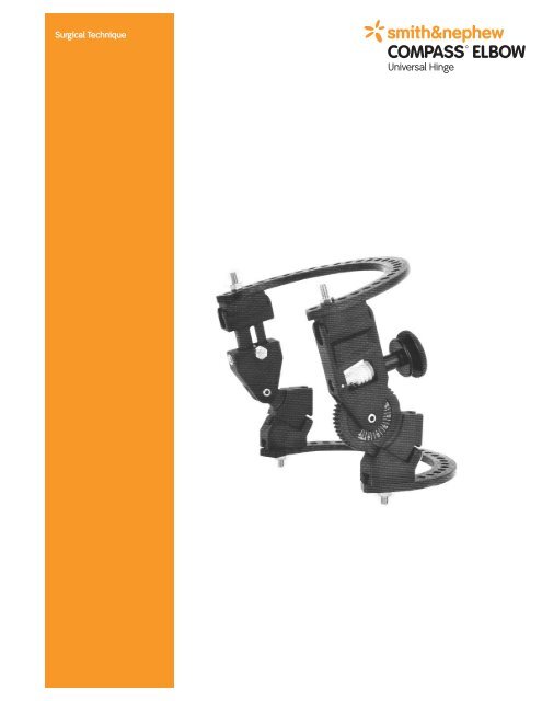
Surgical <strong>Technique</strong><br />
COMPASS ELBOW<br />
Universal <strong>Hinge</strong>
<strong>Compass</strong> <strong>Elbow</strong> Universal <strong>Hinge</strong><br />
By: Robert N. Hotchkiss, M.D.<br />
Chief of Surgery, The Hospital for Special Surgery<br />
Associate Attending, The Hospital of Special Surgery<br />
New York, New York<br />
Table of Contents<br />
Introduction 3<br />
Design Rationale 6<br />
Design Features 7<br />
Surgical <strong>Technique</strong> 8<br />
Catalog Information 30<br />
Nota Bene: The technique description herein is made available to the healthcare professional to<br />
illustrate the author’s suggested treatment for the uncomplicated procedures. In the final analysis,<br />
the preferred treatment is that which addresses the needs of the specific patient.
Introduction<br />
This technique defines the indication for<br />
application and use of the <strong>Compass</strong><br />
Universal <strong>Hinge</strong> on the elbow.<br />
Flexion contractures in the elbow are quite<br />
common after trauma to the joint and<br />
represent one of the major challenges in the<br />
care of these injuries. These disabling<br />
contractures may also occur after burns or<br />
the development of arthritis. Even minor<br />
contractures (30° to 40°) can significantly<br />
reduce function of the upper extremity.<br />
However, regaining a functional range of<br />
motion after open release or distraction<br />
arthroplasty may be precluded by pain,<br />
swelling, and adaptive shortening of the<br />
muscle tendon unit on both sides of the joint.<br />
Until now, there was no effective method of<br />
increasing the motion of the elbow following<br />
trauma or contracture release. Neither early<br />
active motion, comprehensive therapy,<br />
dynamic splints, nor CPM ensure success.<br />
Early active motion, while reducing the<br />
severity of contracture, requires the patient’s<br />
own strength and constant effort. Passive<br />
stretching by a therapist risks the formation<br />
of heterotopic bone and myositis ossificans.<br />
Dynamic splints are useful, but require<br />
pressure on the soft tissues of the arm,<br />
reducing patient compliance. Finally, CPM<br />
devices provide early motion gains, but do<br />
not allow the joint to reach the extremities of<br />
motion which are the areas of greatest need.<br />
3
Introduction<br />
The <strong>Compass</strong> universal hinge, however,<br />
addresses the challenge of maintaining or<br />
even enhancing the range of position. It<br />
allows both passive and active movement of<br />
the elbow through a kinematically normal<br />
range of motion while stretching the soft<br />
tissue capsule at the extremes of flexion and<br />
extension. The result is a significant reduction<br />
in joint contracture without the drawbacks<br />
inherent in the previously discussed<br />
methods. In addition, patients with instability<br />
or massive injury following trauma may be<br />
mobilized early after repair and placement of<br />
internal fixation.<br />
The Indications<br />
The indications for use of the <strong>Compass</strong> <strong>Hinge</strong><br />
include the following:<br />
1. Acute trauma with instability.<br />
2. “Cold” or delayed trauma to the elbow with<br />
subsequent instability.<br />
3. Stiff elbow.<br />
4. The arthritic elbow with posttraumatic<br />
arthritis with and without cartilage injury.<br />
4
Design Rationale<br />
The elbow (ulno-humeral articulation) is one<br />
of two joints which approximates a hinge<br />
(ginglymus). Only slight movement of the<br />
instant center of rotation occurs at the elbow<br />
during flexion and extension. Care must be<br />
taken, therefore, to locate the rotational axis<br />
of the elbow for proper treatment.<br />
The <strong>Compass</strong> Universal <strong>Hinge</strong> uses the<br />
anatomic axis of the elbow as the mechanical<br />
axis of the device. The mechanical axes of<br />
the device’s bilateral hinges are aligned<br />
coincident with the anatomic axis of the joint.<br />
The alignment can be verified throughout the<br />
course of application and treatment.<br />
Once engaged, the <strong>Compass</strong> <strong>Hinge</strong>’s<br />
precision worm gear permits passive<br />
mobilization of the elbow joint. This<br />
movement gently stretches the soft tissue<br />
capsule and muscle tendon during flexion<br />
and extension. Stress, relaxation and<br />
elongation increase the range of motion and<br />
range of position. Gentle, intermittent, passive<br />
displacement allows improvement or<br />
maintenance of a maximal range of motion<br />
(ROM) during hinge wear. The worm gear<br />
mechanism may also be disengaged to<br />
permit the patient to exercise active ROM.<br />
The Ilizarov method emphasizes incremental<br />
passive displacement to allow soft tissue<br />
accommodation during limb lengthening and<br />
bone regeneration. With the <strong>Compass</strong><br />
Universal <strong>Hinge</strong>, those same principles<br />
establish and maintain a maximal range of<br />
motion after contracture release, distraction<br />
arthroplasty, or trauma.<br />
6
Precision Worm Gear.<br />
The <strong>Compass</strong> Universal<br />
<strong>Hinge</strong> incorporates a<br />
precision worm gear that<br />
provides controlled<br />
displacement throughout<br />
the extremes of flexion<br />
and extension.<br />
Design Features<br />
Matching Axes of Rotation. The <strong>Compass</strong> Universal <strong>Hinge</strong> aligns its mechanical axis with the anatomic<br />
axis of the joint – elbow, knee, or angle. This allows the hinge to work with the joint, gently moving it<br />
through a biomechanically normal range of motion. A choice of passive or active modes ensures the<br />
greatest therapeutic value for each individual patient. As with the original design, radiolucent<br />
construction allows accurate alignment of the axes during hinge application. Once the hinge is placed,<br />
the axis reference pin is removed to reduce the likelihood of infection of the joint capsule.<br />
Range of Valgus.<br />
The self-telescoping design<br />
of the <strong>Compass</strong> Universal<br />
<strong>Hinge</strong> allows a full range of<br />
10° varus to 10° of valgus,<br />
allowing quick, easy and<br />
anatomically appropriate<br />
application to the knee,<br />
ankle, or elbow.<br />
Displacement/Distraction.<br />
Distraction screws allow the surgeon<br />
to distract the joint as needed.<br />
Versatility.<br />
The <strong>Compass</strong> Universal <strong>Hinge</strong><br />
offers great versatility for use on<br />
the elbow, the knee, or the ankle<br />
– and requires only a few simple<br />
adjustments for any application.<br />
Radiolucent Arcs.<br />
The <strong>Compass</strong> Universal <strong>Hinge</strong> is<br />
fully compatible with the Ilizarov<br />
system to provide a wide variety<br />
of fixation options.<br />
Lower Profile.<br />
The <strong>Compass</strong> Universal <strong>Hinge</strong> is lighter in weight<br />
and lower in profile than the original design. This<br />
improves patient comfort with the device and patient<br />
compliance throughout the healing process.<br />
7
Surgical <strong>Technique</strong><br />
Frame Assembly<br />
The frame should be prebuilt to confirm that<br />
proper ring size has been selected. It is<br />
important that the geared component is<br />
always medial with the knob facing posterior.<br />
Before tightening the rings to the hinge<br />
components, place an axis pin through the<br />
center of the hinges (Figure 1). Then tighten<br />
the rings to the connecting blocks with a 10<br />
mm wrench (Figure 2). Make sure that<br />
countertorque is applied to the hinge<br />
components to ensure that they maintain<br />
alignment on the axis pin.<br />
When the frame has been assembled and<br />
appropriately adjusted, it is helpful to test the<br />
alignment of the frame relative to the axis pin.<br />
A properly aligned frame should slide along<br />
the axis pin (M/L and L/M) without significant<br />
impingement (Figure 3). If the ring is too large<br />
or too small, adjustments can be made at this<br />
point to switch to either a larger or smaller<br />
ring bringing the hinge components either<br />
closer or farther away from the joint. Make<br />
sure that you allow for swelling in the<br />
postoperative period, allowing at least 2 cm of<br />
clearance from the skin to the hinge block at<br />
the time of surgery and at least two finger<br />
breadths posteriorly at the level of the elbow<br />
with the posterior portion of the ring. Make<br />
sure that the proximal ring is perpendicular to<br />
the humerus from the later view.<br />
The valgus angle of the hinge can be<br />
adjusted by loosening the set screw on the<br />
lateral component and rotating the 10 mm<br />
Hex (Figure 4). Retighten the set screw when<br />
ring is perpendicular to the shaft of the bone.<br />
8<br />
Figure 1<br />
Figure 2
Figure 3<br />
Figure 4<br />
Surgical <strong>Technique</strong><br />
Preoperative Planning<br />
Contracture Release<br />
Before embarking on the surgical release,<br />
care should be taken to ensure that the<br />
injured joint is scrutinized for the existences<br />
of heterotopic bone. Loss of pronation and<br />
supination must also be considered, as well<br />
as the loss of flexion and extension. Lateral<br />
polytomography and/or CAT scanning should<br />
be performed to look for bone bridging<br />
the defect.<br />
Once the determination is made that the<br />
patient is suitable for contracture release<br />
and the use of the <strong>Compass</strong> <strong>Hinge</strong>, a long<br />
discussion with the patient concerning<br />
length of treatment should be undertaken.<br />
The patient needs to understand that he/she<br />
will wear this device for at least six to eight<br />
weeks. There are frequently problems<br />
associated with the pins and proper care<br />
of these pins and earnest efforts by the<br />
patient are required to make this procedure<br />
a success.<br />
9
Surgical <strong>Technique</strong><br />
Patient Positioning<br />
For release of contracture and removal of<br />
heterotopic bone, the patient should be<br />
placed in the supine position with the arm on<br />
a radiolucent hand table. It is important to<br />
prep the patient all the way to the shoulder<br />
and axilla and a sterile tourniquet should be<br />
used. It is very important to position the<br />
patient so that the proximal portion of the<br />
arm/humerus is as lateral as possible. The<br />
shoulder should be at the very edge of the<br />
operating table. A donut may be necessary to<br />
support the head. If this is not done, it is<br />
difficult to visualize the proximal portion of<br />
the pins and their location in the humerus.<br />
If the patient first requires a more extensive<br />
exposure of the distal humerus for fracture or<br />
reconstructive work, it may be useful to begin<br />
the operation with the arm over the chest<br />
when using one or more standard posterior<br />
approaches to the elbow, either olecranon<br />
ostectomy or a triceps sparing exposure<br />
(Bryan/Morrey). Once the fracture work is<br />
completed, the patient can then be made<br />
more supine and the hand table inserted<br />
under the drapes and the patient placed in<br />
the position as depicted in Figure 5, for the<br />
application of the <strong>Compass</strong> <strong>Hinge</strong>.<br />
10<br />
Figure 5
Figure 6<br />
Figure 7<br />
Figure 8<br />
Incision<br />
Tourniquet<br />
Flexi Carpi<br />
Radialis Muscle Biceps Muscle<br />
Pronator Teres<br />
Muscle<br />
Brachialis Muscle<br />
Medial Epicondyle<br />
of Humerus<br />
Ulnar Nerve<br />
Exposed<br />
Anterior<br />
Capsule<br />
Intermuscular<br />
Septum<br />
Partially Cut<br />
Origin of Pronator<br />
Teres Muscle<br />
Triceps Muscle<br />
Medial Head<br />
Median Nerve &<br />
Brachial Artery<br />
Protected<br />
Brachialis Muscle<br />
Biceps Brachi<br />
Muscle<br />
Excised Intermuscular<br />
Septum<br />
Surgical <strong>Technique</strong><br />
Anterior Exposure of the Joint<br />
The Modified “Over the Top”<br />
Exposure of the <strong>Elbow</strong><br />
Incision – The skin incision may be<br />
predetermined from previous surgery. The<br />
incision can vary from posterior to medial. For<br />
nearly all applications, especially those<br />
patients who have contractures from trauma<br />
about the elbow and who lack significant<br />
flexion, it is important to transpose the ulnar<br />
nerve (Figure 6). The skin incision must be<br />
extensive enough to allow exposure of the<br />
ulnar nerve along its entire course, as well as<br />
exposure of the elbow and distal humerus.<br />
The most proximal portion of the incision<br />
allows direct visualization of the distal-middle<br />
humerus for placement of the medial pin.<br />
Using the medial incision, the ulnar nerve can<br />
be mobilized and will allow exposure of both<br />
the anterior and posterior elbow joint (Figure<br />
7). After the ulnar nerve is mobilized and the<br />
intermuscular septum excised, the anterior<br />
distal humerus and capsule are exposed by<br />
elevating the most proximal origin of the<br />
flexor muscle mass (the flexor carpi ulnaris<br />
[FCU]) is left attached to the medial<br />
epicondyle. Superior to the origin of the<br />
capsule, the subperiosteal dissection is<br />
carried out to the distal humerus and a<br />
Bennett retractor or a blunt Hohmann can be<br />
inserted over the anterior surface of the<br />
bone.<br />
With the flexor pronator muscle mass<br />
elevated as depicted in Figure 7, the anterior<br />
muscle of the brachialis and biceps can be<br />
separated from the anterior capsule, thereby<br />
fully exposing the elbow joint (Figure 8 Inset).<br />
Heterotopic bone encountered at this time<br />
can also be excised. The principle danger in<br />
this exposure is excessive traction on the<br />
median nerve and brachial artery which are<br />
bordering the lateral aspect of the muscular<br />
incision (Figure 8).<br />
11
Surgical <strong>Technique</strong><br />
There is usually a sufficient amount of<br />
brachialis muscle to protect the median nerve<br />
from direct contact with the anterior<br />
retractors. The most distal extent of the<br />
muscle split, at the flexor pronator origin,<br />
should not be lengthened without<br />
identification of the branches of the median<br />
nerve to the Pronator Teres. Once the capsule<br />
is exposed, it can be excised from proximal to<br />
distal (Figure 9). The most superior portion of<br />
the elbow joint can be visualized at this point<br />
and excision carried out from medial to<br />
lateral. Flexion of the joint itself relaxes<br />
tension to the anterior structures and often<br />
affords a better view. It is sometimes<br />
necessary to use a headlight to see all the<br />
way across as the capsular excision is<br />
performed. Each case is different and at this<br />
point the surgeon, using the medial exposure,<br />
must decide whether a full anterior release<br />
has been accomplished. If there is extensive<br />
heterotopic bone or concern over further scar<br />
and contracture at the lateral side, it may be<br />
necessary to perform a lateral exposure<br />
through a supplementary incision along the<br />
supracondylar ridge of the distal humerus.<br />
This need only be as extensive as necessary<br />
to complete the capsular incision and removal<br />
of heterotopic bone.<br />
12<br />
Figure 9<br />
Excised Anterior Capsule
Poesterior Capsular<br />
Excision<br />
Olecranon<br />
Figure 10<br />
Figure 9<br />
Hererotopic<br />
Bone<br />
Ulnar Nerve<br />
Surgical <strong>Technique</strong><br />
Posterior Exposure of the Joint<br />
Once the anterior release is completed, there<br />
is usually little gain in extension of flexion<br />
because of contracture and accumulated soft<br />
tissue in the olecranon fossa posteriorly.<br />
Often heterotopic bone posterior to the<br />
olecranon also limits motion. The ulnar nerve<br />
must now be mobilized and transposed<br />
anteriorly. A vessel loop is usually used to<br />
accomplish this; however, it is somewhat<br />
dangerous to apply a hemostat or clamp to<br />
the loop for fear that inadvertent, sudden<br />
retraction could injure the nerve. With the<br />
nerve held anteriorly, the posterior exposure<br />
can then be performed (Figure 10). Similar to<br />
the anterior approach, a subperiosteal<br />
dissection and retraction of the triceps at the<br />
distal humerus is first performed with<br />
insertion of a Hohmannn retractor posteriorly<br />
separating the distal humerus from the<br />
triceps. In cases of posttraumatic adherence<br />
and burns, there is often a great deal of<br />
adherence all along the triceps to the<br />
exposure distally. Once the retractor is in<br />
place, the capsule of the posterior elbow joint<br />
can be exposed and excised (Figure 11). The<br />
entire posterior portion of the collateral<br />
ligament can be removed between the<br />
humerus and ulna. The anterior portion of the<br />
medial collateral ligament is protected by the<br />
overlying origin of the flexor carpi ulnaris<br />
muscle mass that has not been elevated.<br />
Once the capsule is exposed and excised<br />
posteriorly, a complete excision of the<br />
heterotopic bone and impinging<br />
13
Surgical <strong>Technique</strong><br />
portion of the olecranon must be achieved<br />
(Figure 12). It is sometimes difficult to see all<br />
the way over to the lateral aspect of the<br />
olecranon for an adequate excision. Again, a<br />
supplementary lateral incision is occasionally<br />
necessary. Once the entire capsular release<br />
has been achieved both posteriorly and<br />
anteriorly, the elbow usually exhibits improved<br />
mobility. The anterior and posterior structures<br />
can still be quite tense or tight. Excessive or<br />
forceful manipulation is ill-advised. However,<br />
gentle, sustained pressure can be applied<br />
and manipulation of the elbow can be<br />
performed to maximize flexion and extension.<br />
Closure – Before closing the entire wound,<br />
the ulnar nerve should be transposed and<br />
held with a fascial sling (Figure 13). The fascial<br />
sling should be constructed in a way that<br />
does not constrict the nerve and, during<br />
flexion and extension of the elbow, does not<br />
allow the nerve to subluxate nor become<br />
entrapped. It is sometimes necessary to<br />
make a small groove in the fascia of the<br />
flexor carpi ulnaris so that the nerve is<br />
not compressed.<br />
This is also the time that the first medial pin<br />
can be placed with direct visualization. It is<br />
usually best placed posterior to the anteriorly<br />
transposed ulnar nerve; however, it<br />
sometimes can be placed anterior to the<br />
nerve, depending on the extent of release.<br />
The level of the pin placement is determined<br />
by placing the <strong>Compass</strong> <strong>Hinge</strong> first over the<br />
elbow and noting where it lies. Most of the<br />
wound can be closed leaving only the<br />
exposure of the distal humerus.<br />
14<br />
Excised Posterior<br />
Capsule<br />
Figure 12<br />
Figure 13<br />
Ulecranon<br />
Ostectomy<br />
Transposed<br />
Ulnar Nerve<br />
Fascial Sling<br />
for Ulnar Nerve<br />
1st. Medical Pin
Figure 14<br />
Figure 15A<br />
Figure 15B<br />
Axis of Rotation<br />
Surgical <strong>Technique</strong><br />
Axis Pin Placement<br />
There are two methods that can be used for<br />
axis pin placement. The temporary axis pin<br />
aligns the hinge to the axis of rotation. Proper<br />
placement is crucial. Remember that the<br />
center axis pin is removed from the distal<br />
humerus at the end of the case.<br />
Method 1 (Single pin technique)<br />
Where you can easily visualize the axis of the<br />
distal humerus, the axis pin may be placed<br />
under direct vision. This may be the case with<br />
an extensive contracture release or gross<br />
instability. In these cases, it is not uncommon<br />
to have the entire distal humerus exposed.<br />
In this setting, simply identify the starting<br />
point; usually this is easier on the lateral side.<br />
Imagine that the distal humerus is a spool<br />
sitting on the end of a column. The goal is to<br />
place the pin perfectly in the center of<br />
rotation of that spool. The axis is distal to<br />
both the medial and lateral epicondyles<br />
(Figure 14).<br />
Take the 3.5 mm axis pin through either the<br />
medial or lateral side of the exposed joint,<br />
place the pin centrally and begin drilling to<br />
start the hole in the alignment that is as close<br />
to the axis as possible. Confirm the alignment<br />
either by C-arm in the A/P plane or by direct<br />
visualization at this time.<br />
The alignment of the axis is crucial. It is<br />
important to take the time necessary to<br />
achieve perfect placement of this pin for<br />
alignment of the <strong>Compass</strong> <strong>Hinge</strong> at the<br />
elbow. Both an A/P and lateral should be<br />
viewed to ensure adequate placement<br />
(Figures 15A and 15B).<br />
15
Surgical <strong>Technique</strong><br />
Method 2 (Two pin technique)<br />
More commonly, the distal humerus is<br />
visualized incompletely, but exposed on both<br />
the medial and lateral sides. In this case the<br />
surgeon must have a competent assistant to<br />
help with axis pin placement.<br />
1. Preassemble the frame using the proper<br />
size rings. Make certain that the frame<br />
can rotate on its hinges. The gear portion<br />
is usually located on the medial side.<br />
2. Both surgeons identify the center point on<br />
the distal humerus, medial and lateral, the<br />
axis of rotation.<br />
3. The hinge is now brought into position<br />
and held by hand.<br />
4. Starting with the medial side, the surgeon<br />
pushes the 3.5 mm axis pin through the<br />
frame, by hand, into the center of rotation<br />
as viewed from the medial side. This point<br />
is located just distal and anterior to the<br />
medial epicondyle (Figure 16). This medial<br />
pin is held at this point during the<br />
placement of the axis pin from the<br />
later side.<br />
5. From the lateral side, the second surgeon<br />
carefully pushes a second 3.5 mm pin<br />
through the axis hole to the center of<br />
rotation, as viewed from the lateral<br />
position (Figure 17).<br />
16<br />
Figure 16<br />
Figure 17
Figure 18<br />
Surgical <strong>Technique</strong><br />
6. The two axis pins must now be adjusted<br />
into alignment. Neither pin should be<br />
moved from their respective point of<br />
entry, as this reflects the axis of rotation,<br />
but rather the angle of entry adjusted<br />
until the frame itself can easily be slid<br />
medial to lateral, back and forth, assuring<br />
uniaxial alignment (Figure 18).<br />
7. Once the two pins are coincident,<br />
entering at their respective centers of<br />
rotation, the lateral pin is driven in<br />
approximately 2 cm by power. Again, a<br />
check should be made that driving the<br />
lateral pin in did not cause the medial<br />
pin, held by hand, to shift. The frame<br />
should still be easy to slide from medial<br />
to lateral, back and forth, before driving<br />
in the pin from the medial side<br />
(Figure 18).<br />
8. The medial pin is then drilled in,<br />
approximately 2 cm under power.<br />
9. A check is made that the frame still can<br />
slide freely from medial to lateral.<br />
10. An A/P fluoroscopic view is checked. A<br />
lateral may also be checked if desired,<br />
however, with experience, this becomes<br />
unnecessary since you have been able to<br />
visualize both sides of the axis at the<br />
time of pin placement.<br />
17
Surgical <strong>Technique</strong><br />
Half-Pin Placement<br />
Rancho <strong>Technique</strong> for Placement of Half-Pins<br />
1. Determine the desired position of the pin<br />
location and angle.<br />
2. Build a cube assembly that allows the<br />
particular pin placement. This may be a<br />
cube attached directly to a ring. It may be<br />
hinged for proximal-distal angulation. The<br />
hinged construct is built by attaching a<br />
cube to a hinge or post with a bolt. A star<br />
washer is used between the cube and post<br />
to resist rotation of the cube and possibly<br />
loosening of the bolt. An 8 mm bolt should<br />
be used, especially for the one hole cube,<br />
so that this bolt does not interfere with the<br />
large hole in the cube through which the<br />
guide sleeve and pin pass.<br />
3. The drill guide is passed through the large<br />
hole. It should touch the skin and be in the<br />
location and direction desired for the pin.<br />
4. Lift the guide so that an incision can<br />
be made.<br />
5. Make an incision and separate the soft<br />
tissues and periosteum so that the drill<br />
guide rests on bone. The drill guide has a<br />
concave tip that reduces slipping.<br />
6. Lightly lock the drill guide in place with a<br />
set screw or a bolt.<br />
7. Using the appropriate size of drill and<br />
accepted techniques for reducing heat<br />
transfer to the bone, drill carefully through<br />
bone cortices. Bone thickness can be<br />
determined by reading the number of<br />
millimeters indicated on the drill shank at<br />
the top of the guide.<br />
18
Surgical <strong>Technique</strong><br />
8. Thickness from cortex to cortex can also<br />
be determined by hooking the tip of the<br />
depth gauge on the outside of the far<br />
cortex and reading the number of<br />
millimeters at the top of the guide.<br />
9. Choose the appropriate thread length<br />
designed by measurement and place the<br />
pin through the guide using the driverextractor.<br />
Manual placement is<br />
recommended. The Smith & Nephew<br />
half-pins are self-tapping.<br />
10. Once the pin is firm in both cortices<br />
(X-ray verification is helpful), remove the<br />
drill guide.<br />
11. Slide the proper size of centering sleeve<br />
over the pin. Align the bold line on the<br />
head to point to the threaded hole to be<br />
used to lock the pin. This allows the bolt<br />
or set screw to impinge the pin directly<br />
ensuring a more secured lock.<br />
12. Ensure all connections are<br />
tightened securely.<br />
13. After each pin placement, check<br />
alignment of elbow and hinge axis.<br />
4 mm pins use a 2.7 mm drill<br />
5 mm pins use a 3.8 mm drill<br />
19
Surgical <strong>Technique</strong><br />
Humeral Pin Placement<br />
Two half pins are placed, one medial and the<br />
other lateral. The principle is to secure the<br />
humerus in two places, without impaling<br />
any of the major muscle-tendon units or<br />
jeopardizing any neurovascular structures.<br />
1. The medial pin is usually placed first<br />
through a two-hole Rancho cube on<br />
the undersurface of the upper ring<br />
(Figure 19A).<br />
2. The medial pin will be close to the ulnar<br />
nerve and should run along the medial<br />
intermuscular septum.<br />
3. As this pin is drilled, care should be taken<br />
to ensure that the upper 5/8 ring is not<br />
flexed or extended, but perpendicular to<br />
the humerus (Figures 19B and 19C).<br />
4. Both cortices should be engaged.<br />
20<br />
Figure 19A<br />
Figure 19B<br />
Figure 19C
Figure 20<br />
Surgical <strong>Technique</strong><br />
The lateral pin is usually placed using a<br />
two-hole post and a single-hole Rancho cube.<br />
1. The lateral flare of the humerus is<br />
used for placement.<br />
2. The drill guide rests on the lateral<br />
supracondylar ridge, directed anterior<br />
and distally. The radial nerve, at this<br />
level, is posterior to the pin.<br />
It is helpful to envision and place the<br />
posterolateral humeral pin just anterior to the<br />
triceps pin but directed from posterolateral to<br />
anteromedial. The radial nerve is now anterior<br />
to this pin. A Rancho cube below the humeral<br />
5/8 ring is used to fix this pin (Figure 20).<br />
At this time, assure that the alignment of the<br />
axis is acceptable. Modifications of position<br />
from anterior to posterior are possible using<br />
the sliding 5/8 ring attachment assemblies.<br />
21
Surgical <strong>Technique</strong><br />
Placement of Ulnar Fixation<br />
It is important at this point to assure that the<br />
distraction component is well-seated. Again<br />
using the Rancho System, two or three 4 mm<br />
pins are used in the ulna. The more proximal<br />
pin provides better control and can be placed<br />
up and through the coronoid. Spacing the<br />
pins along the subcutaneous border of the<br />
ulna allows excellent rotational control. If the<br />
elbow is grossly unstable, it is quite important<br />
to reduce the elbow before placing the ulnar<br />
pins. It is often helpful to place the elbow in<br />
approximately 90° of flexion when applying<br />
the ulnar fixation. If a distraction arthroplasty<br />
is performed and the elbow is grossly<br />
unstable, it is possible to have translated the<br />
ulna on the humerus without knowing this. It<br />
is therefore helpful, if there is any concern<br />
about this, to view the joint under the C-arm<br />
in the A/P plane before proceeding with<br />
ulnar fixation.<br />
Once the joint is reduced and held in<br />
position, the first proximal ulnar pin can be<br />
placed using a two-hole post (Figure 21). This<br />
is tightened into place on the ring<br />
perpendicular to the ulna. A second pin can<br />
be placed as well (Figure 22). Again, because<br />
of the size and the trefoil shape of the ulna, it<br />
is sometimes frustrating when placing these<br />
pins and great patience may be necessary to<br />
predrill and achieve bicortical fixation of the 4<br />
mm pins. Once the first two pins are in place,<br />
ranging through flexion and extension and<br />
assuring reduction of the joint is important.<br />
If there is a tendency for the elbow to<br />
subluxate, then alignment has not been<br />
achieved and the bolts must be loosened<br />
and reduction achieved.<br />
22<br />
Figure 21<br />
Figure 22
Surgical <strong>Technique</strong><br />
In summary, the assembly is as follows:<br />
1. The axis pin is placed across the distal<br />
humerus using a 3.5 mm pin.<br />
2. The hinge – the medial gear block and the<br />
lateral hinge block are slid onto the axis<br />
pin and using the ring of appropriate size,<br />
the hinge blocks are connected and<br />
affixed firmly using the hinge block<br />
connectors through the bolts. If there is<br />
valgus alignment, it needs to be adjusted.<br />
Loosen set screw on lateral component<br />
and rotate 10 mm Hex until ring is in<br />
proper alignment. Tighten set screw.<br />
3. The alignment of the hinge relative to tilt<br />
axis pin is confirmed by sliding the frame<br />
along the pin. The proximal medial and<br />
the proximal lateral half pin is placed<br />
using the 3.8 mm drill and 5 mm half<br />
pin (in most adults).<br />
The second pin is placed and then the<br />
optional third pin is placed on the<br />
lateral side.<br />
23
Surgical <strong>Technique</strong><br />
4. Before the axis pin is removed, confirm<br />
that the hinge rotates appropriately.<br />
5. The ulnar assembly, or the fixation of the<br />
ulna is then performed. Ensure that the<br />
joint tracks appropriately and that the<br />
distractor blocks are flush at this<br />
zero position.<br />
6. Next, the ulna is placed in the reduced<br />
position at approximately 90° and the<br />
first 4 or 5 mm pins is placed proximally<br />
followed by a second and/or third pin<br />
if needed. These are extended down<br />
distally and kept on the subcutaneous<br />
border of the ulna.<br />
Again, the axis pin is kept in place if possible,<br />
taken through a range of motion to determine<br />
that the hinge is functioning well actively and<br />
passively. And finally, the axis pin is removed.<br />
All pin lengths should be checked by C-arm<br />
to ensure proper length and alignment, and<br />
finally, cut off at the appropriate length. Before<br />
leaving the operating room, confirm that all<br />
connections are tightened including the half<br />
pins to the frame.<br />
24
Figure 23<br />
Surgical <strong>Technique</strong><br />
Application of Distraction<br />
Once the joint has been reduced and all<br />
pins applied, distraction can then be<br />
applied to the system through the distraction<br />
mechanism. Distraction is achieved by turning<br />
the bolts located on the ulnar ring fixation<br />
blocks (Figure 23). Both sides of the hinge<br />
should be distracted an equal amount. Use<br />
of distraction should be done at the discretion<br />
of the surgeon.<br />
Again it is helpful to check the entire<br />
range of motion of the elbow. It is often<br />
impossible to achieve full extension or full<br />
flexion immediately on the table after this<br />
release because of static and resting length<br />
contracture of both the triceps and biceps<br />
and brachialis muscle masses. It is<br />
nonetheless helpful to achieve as much<br />
as possible.<br />
Immediate Postoperative Dressings<br />
A light dressing is applied around the<br />
<strong>Compass</strong> <strong>Hinge</strong> in the wounds with sponges<br />
and clips over the pins. The axis pin can<br />
be removed at any point once the humeral<br />
fixation is achieved. If the patient’s principle<br />
lack of position has been extension, then<br />
extension to the point of tightness is applied<br />
and the patient goes to the recovery room<br />
in this position. It is important to ensure that<br />
excessive extension is not applied. Brachial<br />
block anesthesia is helpful in creating a<br />
painless extremity, but does preclude<br />
examination for any nerve function. Hemovac<br />
drains are used and left in place for several<br />
days to reduce the amount of potential<br />
hematoma formation. Ice packs around<br />
the elbow are also used to reduce swelling<br />
and inflammation.<br />
25
Surgical <strong>Technique</strong><br />
Postoperative Mobilization<br />
The first few days are spent gradually<br />
improving extension or flexion depending<br />
upon the patient’s needs. CPM is not used,<br />
nor has it been found to be helpful in this<br />
situation. Rather a slow, controlled passive<br />
stretch of the entire elbow is used to<br />
gradually improve and overcome the resting<br />
length of the biceps brachialis and triceps.<br />
Once the swelling and immediate<br />
postoperative edema is resolved, the patient<br />
beings cycling his/her motion from flexion to<br />
extension over a six- to eight-hour period. For<br />
six to eight hours, the patient works on<br />
achieving greater and greater extension,<br />
either alone or under the supervision of the<br />
therapist. With the clutch engaged, gradual<br />
extension is applied increasingly in<br />
accordance with the patient’s tolerance. They<br />
are usually left in extension overnight.<br />
The following day, work is done to achieve as<br />
much flexion as possible, again on a gradual<br />
basis over a period of hours with change in<br />
position applied, as tolerated, as frequently<br />
as every 15-30 minutes. Again, rapid changes<br />
in position are not well tolerated in the early<br />
postoperative period.<br />
26
Surgical <strong>Technique</strong><br />
Widening the range of position is the goal<br />
over the first week and analgesia is<br />
important. If an indwelling brachial block is<br />
possible, this is often quite helpful. If not,<br />
patient controlled anesthesia with intravenous<br />
narcotics, is often the best method.<br />
Nonetheless, it should be appreciated that<br />
this is not comfortable and adequate<br />
analgesia must be given to achieve the<br />
desired result. Indomethecin therapy is also<br />
initiated immediately to reduce the frequency<br />
and extent of heterotopic ossification that is<br />
potential in all of these cases.<br />
The patient’s hand and wrist are often<br />
somewhat unsupported so the use of an offthe-shelf<br />
wrist splint is sometimes helpful.<br />
Once the swelling and soreness have begun<br />
to resolve, the patient is comfortable with the<br />
<strong>Compass</strong> <strong>Hinge</strong>, and the family is taught the<br />
method of gradual stretching and use of the<br />
<strong>Compass</strong> <strong>Hinge</strong>, the patient may be<br />
discharged. At four to five days following the<br />
surgery, the patient may shower with the arm<br />
uncovered. Clean water is obviously<br />
important. A sterile dressing over the wound<br />
with standard sponges over the pin site is the<br />
dressing of choice. Again, ice should be used<br />
liberally for the first week, packed around the<br />
elbow during stretching sessions.<br />
27
Surgical <strong>Technique</strong><br />
First Two Weeks<br />
The first and second weeks are often not<br />
noted for extensive gains, but every effort<br />
should be made to achieve as much range of<br />
position as possible. The patient’s medial pin<br />
often drains serous fluid because of some<br />
motion of the skin at that site.<br />
Again, clean dressings around the pins and<br />
standard pin care are used. If any of the pins<br />
become irritated or inflamed, the patient must<br />
be inspected for excessive skin tension and<br />
the skin released. Oral antibiotics are<br />
sometimes necessary for cellulites around the<br />
pin sites.<br />
The first postoperative visit is usually at one<br />
week following discharge from the hospital.<br />
The patient is asked to keep a record of<br />
his/her range of position and the particular<br />
times a day. This gives the surgeon some<br />
information as to how well the patient is using<br />
the <strong>Compass</strong> <strong>Hinge</strong>. Again the use of a<br />
therapist to help supervise the range of<br />
position is also helpful. Sessions in a therapy<br />
setting with ice and stretching over a half-day<br />
period can be quite beneficial in the early<br />
stages. Again, the overall goal is to overcome<br />
the resting tension in the muscle, both on the<br />
flexor and extensor surfaces of the elbow.<br />
28
Surgical <strong>Technique</strong><br />
Removal<br />
Six to eight weeks following application,<br />
depending upon the patient’s overall<br />
progress, removal of the hinge is generally<br />
done in an outpatient surgery suite.<br />
Gentle manipulation can be performed<br />
at the time. Physical therapy is usually<br />
continued to maintain range of motion<br />
and to regain strength.<br />
29
Catalog Information<br />
<strong>Compass</strong> Universal Set<br />
Cat. No. 7106-0000<br />
<strong>Compass</strong> Universal <strong>Hinge</strong><br />
Cat. No. 7106-0001<br />
(Includes medial gear and lateral<br />
hinge assemblies only)<br />
<strong>Compass</strong> Instrumentation<br />
Sterilization Case<br />
Cat. No. 7106-0004<br />
Tray Accepts:<br />
Description Cat. No. Qty.<br />
1 Hole Rancho Cube 10-3451 2<br />
2 Hole Rancho Cube 10-3452 2<br />
3 Hole Rancho Cube 10-3453 1<br />
4 Hole Rancho Cube 10-3454 1<br />
5 Hole Rancho Cube 10-3455 1<br />
5 mm Centering Sleeve 10-3405 5<br />
Set Screw 11-2727 10<br />
Hex Driver 11-2719 1<br />
2.7 mm Drill 10-3044 1<br />
3.8 mm Drill 10-30456 1<br />
Pin Driver Extractor 11-2716 1<br />
Drill Guide and Trocar 7103-1040 1<br />
Drill Sleeve Adapter 7101-1005 1<br />
Composite 1/2 Pin Arc 150 mm 7110-1555 2<br />
Composite 1/2 Pin Arc 180 mm 7110-1557 2<br />
Composite 1/2 Pin Arc 200 mm 7110-1558 2<br />
8 mm Bolt 10-0550 10<br />
10 mm Bolt 10-3200 20<br />
16 mm Bolt 10-3201 10<br />
20 mm Bolt 10-3203 10<br />
30<br />
Description Cat. No. Qty.<br />
40 mm Threaded Socket 10-0901 4<br />
60 mm Threaded Socket 10-0911 4<br />
Nut 10-3300 40<br />
Thin Washer 10-2700 10<br />
Star Washer 10-2708 5<br />
Half Pin 4 x 20 12-2700 3<br />
Half Pin 4 x 30 12-2702 3<br />
Half Pin 4 x 40 12-2704 3<br />
Half Pin 5 x 20 12-2707 4<br />
Half Pin 5 x 30 12-2709 4<br />
Half Pin 5 x 40 12-2711 4<br />
Half Pin 5 x 50 12-2713 4<br />
130 mm 5/8 Ring 10-1363 2<br />
150 mm 5/8 Ring 10-1364 2<br />
180 mm 5/8 Ring 10-1366 2<br />
200 mm 5/8 Ring 7110-1362 2<br />
13 mm / 10 mm Wrench L20-2002 2<br />
9/64 x 9 (3.5 mm) Steinman Pin 12-8117 6
Notes<br />
31
Orthopaedics<br />
Smith & Nephew, Inc.<br />
1450 Brooks Road<br />
Memphis, TN 38116<br />
USA<br />
Telephone: 901-396-2121<br />
Information: 1-800-821-5700<br />
Orders/Inquiries: 1-800-238-7538<br />
Trademark of Smith & Nephew, Reg. U.S. Pat & Tm. Off.<br />
www.smith-nephew.com<br />
30036203001b 7108-0177 11/04