Installation and Operating Instructions - Truma Gerätetechnik GmbH ...
Installation and Operating Instructions - Truma Gerätetechnik GmbH ...
Installation and Operating Instructions - Truma Gerätetechnik GmbH ...

Create successful ePaper yourself
Turn your PDF publications into a flip-book with our unique Google optimized e-Paper software.
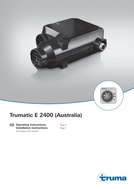
<strong>Truma</strong>tic E 2400 (Australia)<br />
<strong>Operating</strong> instructions Page 2<br />
<strong>Installation</strong> instructions<br />
To be kept in the vehicle!<br />
Page 7<br />
9<br />
9<br />
7<br />
7<br />
4<br />
3<br />
5<br />
<strong>Truma</strong>tic E<br />
5<br />
5<br />
2<br />
3<br />
3<br />
1<br />
1<br />
1
<strong>Truma</strong>tic E 2400 (Australia)<br />
Table of contents<br />
<strong>Installation</strong> example ........................................................... 2<br />
Symbols used ......................................................................... 3<br />
Safety instructions ............................................................. 3<br />
Important operating notes ................................................ 3<br />
<strong>Operating</strong> instructions<br />
Control panel with rotary switch ............................................ 4<br />
Switching on the Heating ...................................................... 4<br />
Switching on the Ventilation .................................................. 4<br />
Switching off .......................................................................... 4<br />
Green LED “Operation” .......................................................... 4<br />
Fuses ...................................................................................... 4<br />
Red LED “Failure” .................................................................. 4<br />
Maintenance ........................................................................ 4<br />
Accessories .......................................................................... 4<br />
Technical data ...................................................................... 5<br />
Dimensions ............................................................................ 5<br />
<strong>Truma</strong> warranty policy ....................................................... 5<br />
Trouble-shooting list ........................................................... 6<br />
<strong>Installation</strong> example<br />
1 Control panel<br />
2 Time switch (accessories)<br />
3 Combustion air<br />
4 Flue gas<br />
5 Electronic control units<br />
6 Power supply<br />
7 Gas connection<br />
W Warm air<br />
U Circulating air<br />
<strong>Installation</strong> options<br />
1<br />
2<br />
<strong>Installation</strong> inside the vehicle<br />
with wall flue kit<br />
<strong>Installation</strong> instructions<br />
Intended use ........................................................................... 7<br />
Approval ................................................................................. 7<br />
Regulations ............................................................................. 7<br />
Choice of location ............................................................... 7<br />
Exhaust duct ........................................................................ 8<br />
Permissible duct lengths ........................................................ 8<br />
Interior installation using the wall cowl kit ................... 8<br />
Assembly of wall cowl ........................................................... 8<br />
Fastening the appliance ......................................................... 8<br />
Double cowl duct connection to the heating<br />
appliance .............................................................................. 8<br />
Warm air distribution <strong>and</strong> circulating air return with<br />
interior installation .............................................................. 9<br />
Warm air distribution ............................................................. 9<br />
Circulating air return ............................................................... 9<br />
Fitting the control panel .................................................... 9<br />
Installing the control panel with rotary switch ...................... 9<br />
Fitting the electronic control units ................................ 10<br />
Electrical connection 12 V ............................................... 10<br />
Gas connection .................................................................. 10<br />
Function check .................................................................. 11<br />
Warning information ........................................................ 11
Symbols used<br />
This symbol indicates possible hazards.<br />
Information <strong>and</strong> advice.<br />
Safety instructions<br />
The use of upright gas cylinders from which gas is taken in<br />
the gas phase is m<strong>and</strong>atory for the operation of gas regulators,<br />
gas equipment <strong>and</strong> gas systems. Gas cylinders from<br />
which gas is taken in the liquid phase (e.g. for fork lifts) must<br />
not be used, since they would result in damage to the gas<br />
system.<br />
If the gas system is leaking or if there is a smell of gas:<br />
– extinguish all flames<br />
– do not smoke<br />
– switch off the appliances<br />
– shut off the gas cylinder<br />
– open windows <strong>and</strong> door<br />
– do not actuate any electrical switches<br />
– have the entire system checked by an expert!<br />
Repairs may only be carried out by an expert!<br />
A new O-ring must always be installed after dismantling the<br />
exhaust duct!<br />
Guarantee claims, warranty claims <strong>and</strong> acceptance of liability<br />
will be ruled out in the event of the following:<br />
– modifications to the unit (including accessories),<br />
– modifications to the exhaust duct <strong>and</strong> the cowl,<br />
– failure to use original <strong>Truma</strong> parts as replacement parts <strong>and</strong><br />
accessories,<br />
– failure to follow the installation <strong>and</strong> operating instructions.<br />
It also becomes illegal to use the appliance, <strong>and</strong> in some<br />
countries this even makes it illegal to use the vehicle.<br />
The gas supply’s operating pressure (2.75 kPa) must be the<br />
same as the unit´s operating pressure (see type plate).<br />
LPG Systems <strong>and</strong> pressure regulators must comply with<br />
the technical <strong>and</strong> administrative regulations of the country<br />
in which the appliance is used. For your own safety it is<br />
absolutely necessary to have the complete gas installation<br />
regularly checked by an expert (at least every 2 years).<br />
The vehicle owner is always responsible for arranging<br />
the gas inspection.<br />
Pressure regulating equipment <strong>and</strong> hoses must be replaced<br />
with new ones no more than 10 years after the date of<br />
manufacture. This is the responsibility of the operator.<br />
Liquid gas equipment must not be used when refuelling, in<br />
multi-storey car parks, in garages or on ferries.<br />
During the initial operation of a br<strong>and</strong> new appliance (or after<br />
it has not been used for some time), a slight amount of fumes<br />
<strong>and</strong> smell may be noticed for a short while.<br />
This will be remedied by running the heater <strong>and</strong> ensuring adequate<br />
room ventilation.<br />
If the burner makes an unusual noise, it is likely that the<br />
gas pressure regulator is faulty <strong>and</strong> it is essential to have it<br />
checked.<br />
Do not place articles on or against this appliance.<br />
Do not use or store flammable materials near this appliance.<br />
Do not spray aerosols in the vicinity of this appliance while it<br />
is in operation.<br />
For the gas supply, only a pressure regulator with a fixed delivery<br />
pressure of 2.75 kPa may be used.<br />
The flow rate of the pressure control device must correspond<br />
to at least the maximum consumption of all devices installed<br />
by the system manufacturer.<br />
Controller connecting hoses that meet national regulations<br />
must always be used in the respective country for which the<br />
equipment is destined. These hoses must be checked regularly<br />
for brittleness. Winter-proof special hoses must always<br />
be used if the equipment is operated during the winter.<br />
Important operating notes<br />
The integrity <strong>and</strong> tight fit of the exhaust gas double duct must<br />
be checked regularly, particularly at the end of long trips. Also<br />
check the mounting of the appliance <strong>and</strong> the cowl.<br />
Following a blow-back (misfire) always have the exhaust gas<br />
system checked by an expert!<br />
Always keep the cowl for conducting exhaust gas <strong>and</strong> supplying<br />
combustion air, free from contamination (slush, leaves<br />
etc.).<br />
The installed temperature limiter shuts off the gas supply if the<br />
appliance becomes too hot. Therefore do not shut the warm<br />
air outlets <strong>and</strong> the opening for the returning circulating air.<br />
The cabin air flow through the heater must not be restricted in<br />
any way. Do not use any after market air filters or air grills.<br />
The use of such components may cause the unit to over heat.<br />
Warning: Air from the discharge vent may be hot. Do not<br />
place combustible materials directly in front of the discharge<br />
vent. Keep curtains, bedding <strong>and</strong> other flammable materials<br />
away from the vent.<br />
Always use original <strong>Truma</strong> parts for maintenance <strong>and</strong> repair<br />
work!<br />
3
Always observe the opera ting instructions <strong>and</strong> “Important<br />
operating notes” prior to starting! The vehicle owner<br />
is responsible for the correct operation of the appliance!<br />
The installer or vehicle owner must apply the yellow sticker<br />
with the warning information, which is enclosed with the appliance,<br />
to a place in the vehicle where it is clearly visible to<br />
all users (e.g. on the wardrobe door)! Ask <strong>Truma</strong> to send you<br />
stickers, if necessary.<br />
Control panel with rotary switch<br />
4<br />
<strong>Operating</strong> instructions<br />
g<br />
f<br />
e<br />
9<br />
7<br />
4<br />
3<br />
5<br />
<strong>Truma</strong>tic E<br />
a = rotary switch (external ring)<br />
b = “Ventilation” rotary switch<br />
c = “Off” rotary switch<br />
d = “Heating” rotary switch<br />
e = green LED lit “Operation”<br />
f = rotary knob for room temperature (1 – 5, 4 ≈ 23 ˚C)<br />
g = red LED lit, red LED blinking “Failure”<br />
5<br />
2<br />
Switching on the Heating<br />
Turn on gas cylinder <strong>and</strong> open quick-acting valve in the gas<br />
supply line.<br />
Adjust desired room temperature at rotary knob.<br />
Switching the heating on:<br />
Set the rotary switch to (d).<br />
Switching on the Ventilation<br />
Set the rotary switch to (b).<br />
Switching off<br />
Set the rotary switch (a) to the centre (c). If the appliance is<br />
switched off after a heating phase, the fan can continue running<br />
in order to make use of the residual heat.<br />
If the appliance is not used for a prolonged period of time,<br />
close quick-acting valve in the gas supply line <strong>and</strong> turn off<br />
gas cylinder.<br />
Green LED “Operation”<br />
(under rotary control knob)<br />
When the appliance is switched on (heating or ventilation)<br />
the green LED must be illuminated (the fan is running). If the<br />
LED is not illuminated, possibly check the (main) switch. For<br />
this purpose observe respective instructions of the vehicle<br />
manufacturer.<br />
During the heating operation, while the flame is burning, the<br />
green LED lights up with twice the intensity. This also makes it<br />
possible to determine the instantaneous switching point of the<br />
room temperature.<br />
3<br />
1<br />
1<br />
a<br />
b<br />
c<br />
d<br />
Fuses<br />
The device <strong>and</strong> control panel fuses are on the electronic control<br />
unit on the device.<br />
Device fuse (F1):<br />
3.15 AT – slow –<br />
Control panel fuse (F3):<br />
1.6 AT – slow –<br />
The fine-wire fuse must only be replaced by a fuse of the<br />
same design.<br />
Red LED “Failure”<br />
Should a failure occur, the red LED is illuminated permanently.<br />
Possible causes for the failure can be e.g. no gas, insufficient<br />
combustion air, heavily soiled fan, defective fuse etc.. Deactivate<br />
by switching off <strong>and</strong> then switching on again.<br />
Flash operation indicates that the operating voltage is too<br />
low (charge battery, if necessary) or too high for the appliance.<br />
Maintenance<br />
The unit must be checked annually for contamination (dust,<br />
dirt, debris) by an expert <strong>and</strong> cleaned if necessary.<br />
Servicing shall be carried out only by authorised<br />
personnel.<br />
Please contact Dometic Service Centre for service <strong>and</strong> repairs.<br />
Accessories<br />
1 Time switch ZUE 2<br />
for pre-programming 3 switch-on times within 7 days,<br />
including 4 m connecting cable (suitable for 12 V vehicle<br />
electrical system).<br />
2 Remote sensor FFC 2<br />
monitors the room tem perature independent of the position<br />
of the control panel (with 4 m connecting cable).<br />
3 Multiple box MSD<br />
for connecting several accessories (e.g. time switch <strong>and</strong><br />
remote sensor).<br />
Extension cable for accessories<br />
items 1, 3 of 4 m or 10 m (not illustrated).<br />
All electrical accessories are fitted with a connector <strong>and</strong> can<br />
be connected individually.
Technical data<br />
determined in accordance with AS 4556/2000 or<br />
<strong>Truma</strong> test conditions<br />
Manufacturer<br />
<strong>Truma</strong> <strong>Gerätetechnik</strong> <strong>GmbH</strong> & Co. KG<br />
P.O. Box 1252<br />
85637 Putzbrunn / Munich<br />
Germany<br />
Type of gas<br />
LPG (propane)<br />
Test point pressure<br />
2.75 kPa (see type plate)<br />
Nominal input<br />
8.56 MJ/h<br />
Gas consumption<br />
170 g/h<br />
Air flow rate<br />
Approx. 78 m³/h<br />
Power consumption 12 V<br />
1.1 A<br />
St<strong>and</strong>by<br />
0.01 A<br />
Weight<br />
Heater unit (without control devices) 5.0 kg<br />
Heater unit with peripheral devices (without cowl kit) 6.0 kg<br />
Cowl kit 0.7 kg<br />
Declaration of conformity<br />
The heater E 2400 (Australia) is tested <strong>and</strong> approved according<br />
AS 4556/2000 <strong>and</strong> fulfils the st<strong>and</strong>ard.<br />
The heater complies with the interference suppression<br />
directive 72/245/EEC for vehicle engines with annexes<br />
2004/104/EC, 2005/83/EC <strong>and</strong> 2006/28/EC.<br />
AGA approval number<br />
7550<br />
5375<br />
The right to effect technical modifications is reserved!<br />
Dimensions<br />
370<br />
All dimensions in mm.<br />
110<br />
47<br />
123<br />
248<br />
<strong>Truma</strong> warranty policy<br />
The warranty is given by Dometic Pty Ltd, Building 3B,<br />
Clayton Business Park, 1508 Centre Road, Clayton, Victoria,<br />
3168, for 12 months from the date of purchase against any<br />
defect arising from faulty materials or workmanship.<br />
Repairs will be carried out during normal business hours only by<br />
Dometic Pty Ltd, or its duly authorised service agents, <strong>and</strong> are<br />
subject to the warranty conditions <strong>and</strong> exclusions hereunder.<br />
Warranty conditions<br />
– The company will only provide service on presentation<br />
of proof of purchase, on either the <strong>Truma</strong> product, or the<br />
Caravan / RV / Pleasure Craft in which the <strong>Truma</strong> product<br />
has been installed, to any authorised service agent. The purchaser<br />
must allow the service agent to photocopy the proof<br />
of purchase to facilitate his claim to the manufacturer.<br />
– Warranty repairs can only be performed by authorised service<br />
agents <strong>and</strong> under no circumstances will Dometic reimburse<br />
repairs carried out by unauthorised persons. Tampering<br />
with any part of the product by unauthorised personnel<br />
will automatically void the warranty.<br />
– The product must be used solely for domestic purposes<br />
only. If the product is used for commercial purposes the<br />
warranty is 6 months only.<br />
– Where applicable, the products must be used on the appropriate<br />
electrical voltage, gas type <strong>and</strong> pressure, or fuel<br />
source.<br />
– If at any time during the warranty period any part or parts<br />
are replaced with a part or parts not supplied or approved<br />
by <strong>Truma</strong>, this warranty shall immediately become void.<br />
Important notice<br />
Before calling a service technician please check carefully the<br />
operating instructions, service booklet <strong>and</strong> warranty terms <strong>and</strong><br />
conditions. If the product fails for any of the reasons detailed<br />
therein, or is faulty due to abuse, misuse or improper installation,<br />
then a service fee shall be charged to the purchaser.<br />
If you have any queries regarding the interpretation of the<br />
warranty you should contact Dometic Pty Ltd.<br />
Whilst this book represents service outlets at the time of<br />
printing, changes occur from time to time. Should you have<br />
any queries or wish to locate your nearest authorised service<br />
agent please contact Dometic Pty Ltd.<br />
Warranty does not cover<br />
– Any heater which has been:<br />
(a) Subject to misuse, neglect, accident or alteration by any<br />
person.<br />
(b) Damaged or destroyed by fire, flood, act of God or other<br />
inevitable accident.<br />
– Fair wear <strong>and</strong> tear.<br />
– Damage from foreign substances such as dirt or liquid.<br />
– Travelling expenses or call out fee to <strong>and</strong> from authorised<br />
service agents premises.<br />
– Accommodation or Site Expenses.<br />
– Cleaning of the system or cleaning <strong>and</strong> adjustment of the<br />
gas system. This is considered to be a part of normal product<br />
maintenance.<br />
– Non operation of the heater or resultant damage to the<br />
unit where the heater has been operated in an out of level<br />
situation.<br />
– Freight cost of the appliance or parts, to or from, point of<br />
service or transit damage.<br />
– Dometic / <strong>Truma</strong> are not responsible for resultant loss or<br />
damage sustained by the purchaser.<br />
–<br />
Non operation of the appliance or resultant damage to the<br />
unit where the appliance has not been installed, ventilated,<br />
flued or operated in accordance with the manufacturers<br />
instructions.<br />
Apart from any warranties implied by the Trade Practices Act<br />
1974 or any relevant State legislation all other warranties express<br />
or implied whether arising by virtue of statute or otherwise<br />
are hereby excluded.<br />
5
Trouble-shooting list<br />
6<br />
Fault Cause Rectification<br />
After switching on none of<br />
the LEDs are lit.<br />
The green LED comes on<br />
when the unit is switched<br />
on but the heater does not<br />
operate.<br />
Red LED flashes 1 x per sec.<br />
Red LED flashes 3 x per sec.<br />
Approximately 30 seconds<br />
after the heater is switched<br />
on, the red LED is lit.<br />
After operating for a longer<br />
period of time, the heater<br />
switches to failure.<br />
– No operating voltage.<br />
–<br />
Device fuse or vehicle fuse<br />
defective.<br />
– Check 12 V battery voltage, charge if necessary.<br />
– Check all electrical plug connections.<br />
–<br />
Check the unit or vehicle fuse <strong>and</strong> replace if necessary<br />
(see fuses).<br />
– The temperature setting on – Select higher room temperature at the control panel.<br />
the control panel is lower<br />
than the room temperature.<br />
–<br />
–<br />
–<br />
–<br />
Under-voltage range<br />
10.9 V – 10.5 V.<br />
Over-voltage range<br />
15.8 V – 16.4 V.<br />
Gas cylinder or quick-acting<br />
valve in the gas line is<br />
closed.<br />
Combustion air infeed or<br />
exhaust outlet is sealed.<br />
– Hot-air outlets blocked.<br />
–<br />
–<br />
Recirculated air intake<br />
blocked.<br />
Gas pressure regulator<br />
iced up.<br />
– Charge battery!<br />
–<br />
Check the battery voltage <strong>and</strong> power supply such as<br />
e.g. the charging device.<br />
– Check gas supply <strong>and</strong> open valves.<br />
– Remove cowl cap.<br />
–<br />
Inspect openings for contamination (slush, ice, leaves, etc.)<br />
<strong>and</strong> remove contamination if necessary.<br />
– Check individual outlet apertures.<br />
– Remove blockage from recirculated air intake.<br />
– Use regulator heating (EisEx).<br />
If these measures do not remove the failure, please contact the nearest Dometic Service.
<strong>Installation</strong> instructions<br />
This appliance must be installed by an authorised person.<br />
Non-compliance with installation instructions or incorrect<br />
installation can result in endangerment of persons<br />
<strong>and</strong> property.<br />
This appliance shall be installed in accordance with the manufacturer’s<br />
installation instructions, local gas fitting regulations,<br />
municipal building codes, electrical wiring regulations,<br />
AS 5601/2004 “Gas <strong>Installation</strong>s”, <strong>and</strong> any other statutory<br />
regulations.<br />
Intended use<br />
This device was designed for installing in vehicles (motor<br />
homes <strong>and</strong> caravans). Other applications are also possible<br />
following consul tation with <strong>Truma</strong>.<br />
Vehicles for hazardous materials<br />
Combustion heaters for gaseous fuel are not permitted.<br />
Approval<br />
Declaration of conformity<br />
The heater E 2400 (Australia) is tested <strong>and</strong> approved according<br />
AS 4556/2000 <strong>and</strong> fulfils the st<strong>and</strong>ard.<br />
The heater complies with the interference suppression<br />
directive 72/245/EEC for vehicle engines with annexes<br />
2004/104/EC, 2005/83/EC <strong>and</strong> 2006/28/EC.<br />
AGA approval number<br />
7550<br />
5375<br />
The year when the equipment was first taken into operation<br />
must be indicated with a check on the type plate.<br />
Regulations<br />
Guarantee claims, warranty claims <strong>and</strong> acceptance of liability<br />
will be ruled out in the event of the following:<br />
– modifications to the unit (including accessories),<br />
– modifications to the exhaust duct <strong>and</strong> the cowl,<br />
– failure to use original <strong>Truma</strong> parts as replacement parts <strong>and</strong><br />
accessories,<br />
– failure to follow the installation <strong>and</strong> operating instructions.<br />
It also becomes illegal to use the appliance, <strong>and</strong> in some<br />
countries this even makes it illegal to use the vehicle.<br />
In-vehicle installations must comply with the technical <strong>and</strong><br />
administrative regulations of the respective country of use<br />
(e.g. AS 5601/2004 for vehicles). The national regulations <strong>and</strong><br />
rules must be complied with.<br />
In other countries always observe the respectively valid<br />
regulations.<br />
For further details on the rules <strong>and</strong> regulations in the respective<br />
country of designation, please contact our agencies<br />
abroad (see <strong>Truma</strong> Service Booklet or www.truma.com).<br />
Choice of location<br />
Always install the appliance <strong>and</strong> its exhaust duct in such a<br />
way that it is always easily accessible for service work <strong>and</strong> can<br />
be removed <strong>and</strong> installed easily.<br />
This appliance can be installed without any clearance to combustible<br />
materials providing the surrounding materials will<br />
withst<strong>and</strong> temperatures of up to 85 °C. The flue <strong>and</strong> warm air<br />
ducts can also be installed without clearance providing only<br />
<strong>Truma</strong> components supplied with the appliance are fitted.<br />
Make sure that there is at least 10 mm clearance to combustible<br />
materials around the warm air discharge vent <strong>and</strong> 500 mm<br />
in front of the vent. Locate the vent so that curtains, bedding,<br />
etc. cannot be blown directly in front of or in contact with the<br />
warm air vent.<br />
Steps must be taken to ensure that the warm air outlet of the<br />
heating system is never obstructed (see warm air distribution).<br />
The installation space must have appropriate openings for the<br />
circulating air return (see circulating air return).<br />
Locate the heater in such a way that the cowl can be mounted<br />
on the outside on a surface which is as straight <strong>and</strong> smooth<br />
as possible.<br />
For evenly distributed heating, the installation of the appliance<br />
should be as much in the centre of the vehicle as possible,<br />
<strong>and</strong> in such a way that the air distribution ducts can be routed<br />
with approximately the same length.<br />
The cowl must be placed in such a way that the exhaust gas<br />
cannot find its way into the vehicle interior. The exhaust gas<br />
cowl can only be installed through a vertical wall to the<br />
outside, never through a horizontal surface.<br />
The flue cowl must always vent to outdoors <strong>and</strong><br />
not into any annex or other enclosed area.<br />
This outside surface must be exposed to wind from all<br />
directions <strong>and</strong>, if possible, there should be no trim strips or<br />
covers in this area, mount heater on an appropriate base,<br />
if necessary.<br />
The wall cowl is to be fitted in such a way that no tank nozzles<br />
or tank ventilation apertures are located within 500 mm (R) of<br />
it. In addition, no air discharge apertures for the living area or<br />
window openings may be located with 300 mm of it.<br />
R<br />
300 mm<br />
300 mm<br />
If installing the cowl directly underneath a window<br />
that will be opened, installation of an electric window<br />
switch (part no. 34000-85800) is m<strong>and</strong>atory. The gas unit<br />
must automatically switch itself off using the <strong>Truma</strong> automatic<br />
shut-off facility if the window is opened (Accessories, part no.<br />
39050-00800).<br />
Refer to AS 5601/2004 – Gas <strong>Installation</strong>s, for location requirements<br />
of the flue terminal.<br />
7
Exhaust duct<br />
With the <strong>Truma</strong>tic E 2400 (Australia) only use the <strong>Truma</strong> exhaust<br />
duct AA 24 (part no. 39420-00) with wall cowl <strong>and</strong> the<br />
combustion air supply duct ZR 24 (part no. 39440-00) for the<br />
installation, as the appliance has only been tested <strong>and</strong> approved<br />
with these ducts.<br />
8<br />
A new O-ring must always be installed after dismantling<br />
the exhaust duct!<br />
Permissible duct lengths<br />
Interior installation with wall cowl<br />
(refer to installation variant 1, page 2):<br />
– Duct lengths of up to max. 70 cm can be routed as<br />
ascending duct in any way required, or descending by max.<br />
30 cm.<br />
– Duct lengths from 30 cm to max. 100 cm must be routed<br />
as ascending duct with an ascending angle of min. 45°.<br />
Interior installation using the wall cowl kit<br />
Refer to installation variant, Fig 1 (page 2).<br />
Assembly of wall cowl<br />
Assemble wall cowl on a surface which is as flat as possible<br />
<strong>and</strong> which is exposed to wind from all directions. Drill an<br />
opening (8) measuring 70 mm in diameter (pack wood into<br />
hollow spaces in the area of the cowl opening). Use the provided<br />
rubber seal (10) for sealing. In the event of structured<br />
surfaces, coat with plastic body sealant – do not use silicone.<br />
In the event of a greater wall thickness, first connect the<br />
exhaust double duct to the cowl from the outside.<br />
Slide rubber seal (10) <strong>and</strong> clamp (4) onto the cowl inner<br />
part (11).<br />
5<br />
Ø<br />
70 mm<br />
1<br />
4<br />
8<br />
2<br />
10<br />
9<br />
Top<br />
14<br />
11<br />
12<br />
13<br />
Compress the corrugations of the exhaust duct (1) for the full<br />
width of the clamp (4) as shown in the diagram below. Slide<br />
exhaust duct over the O-Ring (2a) on the flue cowl connection<br />
fitting (2) up to the collar (3). Make sure the flue cowl bend<br />
points upwards. Ensure the edge of the clamp (4) fits over<br />
the collar (3). Tighten the clamp (4) over the collar (3) <strong>and</strong> the<br />
compressed corrugations of the exhaust duct (1) as shown in<br />
the diagram below.<br />
1 4<br />
Coat serrated connection fitting (9) with plastic body sealant –<br />
do not use silicone! – <strong>and</strong> slide over combustion air supply<br />
duct (5).<br />
Fasten cowl inner part (11) with 3 screws (12 – observe installation<br />
position! Mount cowl outer part (13) <strong>and</strong> screw on with<br />
2 screws (14).<br />
Always install a new O-ring following any disassembly!<br />
Fastening the appliance<br />
Depending on the installation position, bolt on the appliance<br />
using fastening strap (a) or mounting brackets (b). Fasten<br />
exhaust double duct to the wall using duct clamp ZR 24 (c), if<br />
necessary (in the scope of delivery).<br />
2a<br />
Double cowl duct connection to the<br />
heating appliance<br />
Compress the corrugations of the exhaust duct (1) for the full<br />
width of the clamp (4) as shown in the diagram below. Slide<br />
exhaust duct over the O–Ring (2b) on the heater connection<br />
fitting (2) up to the collar (3). Ensure the edge of the clamp (4)<br />
fits over the collar (3). Tighten the clamp (4) over the collar (3)<br />
<strong>and</strong> the compressed corrugations of the exhaust duct (1) as<br />
shown in the diagram below. Fasten combustion air supply<br />
duct (5) on the connection fitting (6) using clamp (7).<br />
Always install a new O-ring following any disassembly!<br />
3<br />
2
Warm air distribution <strong>and</strong> circulating air<br />
return with interior installation<br />
Warm air distribution<br />
Hot air suction apertures must be arranged in such a way that<br />
no exhaust gases from the engine or the heating device can<br />
be drawn in. It must be ensured by means of construction<br />
design that the heating air introduced into the vehicle is not<br />
polluted (e.g. by oil vapour). This is achieved, for example,<br />
with air heaters with circulating air operation.<br />
Only use original <strong>Truma</strong> parts for ducting, outlets, fittings<br />
<strong>and</strong> accessories, supplied by Dometic or <strong>Truma</strong>.<br />
Do not use any other parts.<br />
The warm air (W) is blown out from the appliance, either<br />
directly or using a warm air duct VR 80 (80 mm diameter).<br />
Remove grating from warm air outlet of the appliance. Connect<br />
duct VR 80 (80 mm diameter). By positioning a manifold<br />
section, the ducts VR 72 (72 mm diameter), ÜR (65 mm diameter)<br />
or ZR 18 (49 mm diameter) can also be added on.<br />
Use the following table to determine the number of required<br />
air openings in the warm air duct.<br />
Duct length* Number of air openings<br />
up to <strong>and</strong><br />
including 1 m<br />
over 1 m<br />
up to 5 m<br />
at least 1 air opening<br />
at least 2 air openings<br />
(the first air opening after max. 1 m)<br />
5 m a more at least 3 air openings<br />
(the first air opening after max. 1 m)<br />
* In the case of duct branches, the sum of the installed warm<br />
air ducts.<br />
In order to avoid overheating, there must be at least<br />
one air passage which is always open (swivel<br />
nozzle SCW 2).<br />
Secure all duct connections with self-tapping screws. Fasten<br />
ducts with clamps.<br />
The hot air system is individually designed for each vehicle<br />
model using a modular principle. A wide range of accessories<br />
is available for this purpose.<br />
Circulating air return<br />
The circulating air (U) is sucked back into the appliance, either<br />
directly or via a duct piece VR 80 (80 mm diameter).<br />
1. Direct intake: If the appliance is installed in a storage compartment<br />
or such, drill two holes measuring 75 mm in<br />
diameter into it, or make a corresponding opening for the<br />
circulating air return.<br />
Do not obstruct the air passage to the appliance!<br />
2. Circulating air outside the storage area can be drawn in via<br />
a duct piece VR 80 (1) 80 mm diameter (max. 100 cm in<br />
length) <strong>and</strong> returned to the appliance. The storage compartment<br />
can then be used to the full.<br />
Remove protective grating from the connection fitting (3).<br />
Insert duct piece (1) into the grating connection fitting <strong>and</strong><br />
fasten using the available screws. Attach swivel nozzle SCW 2<br />
to the duct end (4).<br />
W<br />
min 0.5m<br />
U<br />
Fitting the control panel<br />
4<br />
1<br />
3<br />
max 1m<br />
Any modification made to the <strong>Truma</strong> components<br />
pertaining to this will lead to the cancellation of the<br />
guarantee <strong>and</strong> to the exclusion of any claims for liability.<br />
The installer (manufacturer) is responsible for providing operating<br />
instructions for the user as well as for the labelling of<br />
the control panels!<br />
When selecting the location, take note that the control panels<br />
must not be subjected to any direct radiant heat. Length of<br />
the connection cable 4 m or 10 m.<br />
Selecting the position of the thermostat is very important,<br />
the reading of the air temperature is taken by the<br />
thermostat, therefore the position of the thermostat needs<br />
to be considered. The thermostat must be placed in an area<br />
away from sunlight or any external source of heat. The position<br />
should be chosen to represent the average air temperature<br />
experienced inside the vehicle.<br />
If installation is only possible behind curtains or in similar<br />
locations with temperature fluctuations, a remote sensor for<br />
the ambient temperature must be used (Accessories).<br />
Installing the control panel with rotary switch<br />
If flush mounting is not possible, <strong>Truma</strong> will supply an<br />
on-surface frame (1 – part no. 40000-52600) as an accessory<br />
on request.<br />
Drill a hole Ø 55 mm in diameter.<br />
Plug the control panel cable (2) into the control panel (3) <strong>and</strong><br />
then fit the rear cover cap (4) as a stress-relieving device.<br />
Push the cable through to the rear <strong>and</strong> lay it to the electronic<br />
control unit.<br />
Secure the control panel with four screws (5) <strong>and</strong> fit the cover<br />
frame (6) in place.<br />
<strong>Truma</strong> offers side parts (7) in eight different colors for<br />
finishing the cover frames (6) in a visually pleasing way.<br />
Please ask your dealer.<br />
2<br />
Ø 55 mm<br />
1<br />
4<br />
<strong>Truma</strong>tic E<br />
4<br />
5<br />
2<br />
3<br />
1<br />
7 6<br />
3<br />
5<br />
7<br />
9
Fitting the electronic control units<br />
Unscrew the cover of the control units (A <strong>and</strong> B).<br />
The plugs on the electronic control units should only be<br />
withdrawn or plugged in if the supply voltage had been<br />
disconnected beforeh<strong>and</strong>. Pull the plug out straight!<br />
Insert the plug on the control panel cable (1) as shown in the<br />
diagram onto the red terminal strip of the control unit (A).<br />
Insert plug (2) – 20-pin – in the grey terminal strip on the<br />
control unit (A).<br />
Insert plug (3) – 10-pin – in the red terminal strip on the<br />
control unit (B).<br />
If a timer switch or a remote sensor is fitted, its plug is to<br />
be inserted on the black terminal strip (control unit – A).<br />
If several accessory components are being used at the same<br />
time, connection is effected via the multiple box (Accessories).<br />
Secure the lower parts with two screws at an easily accessible<br />
location, protected against moisture (must not be heated to<br />
above 65 °C).<br />
Screw the cover of the control units into place.<br />
Electrical connection 12 V<br />
Electric cables, switching units <strong>and</strong> control units for heaters<br />
must be arranged in the vehicle in such a way that their satisfactory<br />
operation cannot be adversely affected under normal<br />
operating conditions. All cables leading to the outside must be<br />
splash proof at the leadthrough opening.<br />
Prior to working on electric components the appliance<br />
must be disconnected from the power supply. Switching<br />
off at the control panel is not sufficient!<br />
When carrying out electric welding work on the body the<br />
appliance connection must be disconnected from the vehicle<br />
electrical system.<br />
If the connections are transposed there is a risk of cable<br />
burning. This also rules out any guarantee or liability<br />
claims!<br />
10<br />
The red cable is positive, the blue cable is negative!<br />
Connect the appliance to the fused vehicle electrical system<br />
(central electrical system 5 – 10 A) using the 2 x 1.5 mm 2<br />
cable, for lengths over 6 m use 2 x 2.5 mm 2 cable. Negative<br />
cable to central ground. For direct connection to the battery<br />
the positive <strong>and</strong> negative cable must be fused. Connections in<br />
Faston terminals, fully insulated (motor vehicle flat connector<br />
system, 6.3 mm).<br />
Do not connect any other consumers to the supply line!<br />
When power packs or power supply units are being<br />
used, note that the output voltage is between 11 V <strong>and</strong><br />
15 V <strong>and</strong> the alternating current ripple is < 1.2 Vpp.<br />
Gas connection<br />
The gas supply’s operating pressure (2.75 kPa) must be<br />
the same as the unit´s operating pressure (see type plate).<br />
The gas inlet connection on the E 2400 (Australia) is a 8 mm<br />
connection.<br />
The gas connecti on fitting on the appliance is not to be shortened<br />
or bent.<br />
To connect, the UNF 1/2" – 20 (SAE Male AN Flare) gas inlet<br />
connection provided with the appliance must be used.<br />
UNF 1/2"<br />
8 mm<br />
For connection to 8 mm steel piping Dometic povides an<br />
adapter UNF 1/2" x RVS 8, part no. 70020-02700.<br />
Before connecting to the appliance make sure that the gas<br />
lines are free from dirt, chips <strong>and</strong> such!<br />
Route the pipes in such a way that the appliance can be<br />
removed again for servicing.<br />
Refer to AS 5601/2004 – Gas <strong>Installation</strong>s, for gas pipe sizing.<br />
The gas inlet connection is preinstalled.<br />
Please check for leaks before starting up for the first time.<br />
Check for gas leaks (do not check for gas leaks with a naked<br />
flame), then check that the gas pressure is as follows:<br />
Propane gas: 2.75 kPa<br />
Keep the number of parting connections in the gas supply<br />
line in rooms frequented by people to a technically feasible<br />
minimum.<br />
The gas system must accord with the technical <strong>and</strong> administrative<br />
provisions of the individual country of use (in Australia,<br />
AS 5601/2004 for motor vehicles). National regulations <strong>and</strong><br />
rulings must be respected.
Function check<br />
After installation, check gas supple line for leaks in accordance<br />
with the pressure drop method.<br />
Always observe the operating instructions prior to starting!<br />
Then check all functions of the appliance, as specified in the<br />
operating instructions.<br />
If the appliance can not be adjusted to perform correctly,<br />
please contact Dometic Service Centre.<br />
The operating instructions <strong>and</strong> completed guarantee card are<br />
to be given to the owner of the vehicle.<br />
Remove the type plate from the operating <strong>and</strong> installation<br />
instructions <strong>and</strong> affix it at a position on the heater which<br />
is clearly visible <strong>and</strong> well protected against damage. The year<br />
of initial operation must be marked on the type plate.<br />
Warning information<br />
The installer or vehicle owner must apply the yellow sticker<br />
with the warning information, which is enclosed with the<br />
appliance, to a place in the vehicle where it is clearly visible<br />
to all users (e.g. on the wardrobe door)! Ask Dometic to send<br />
you stickers, if necessary.<br />
11
In Australia, always notify the Dometic Service Centre<br />
if problems are encountered; in other countries the<br />
relevant service partners should be contacted<br />
(see Service Booklet or www.truma.com).<br />
Having the equipment model <strong>and</strong> the serial number<br />
ready (see type plate) will speed up processing.<br />
Dometic Pty Ltd<br />
Building 3B,<br />
Clayton Business Park<br />
1508 Centre Road<br />
Clayton, Victoria, 3168<br />
Australia<br />
Service (Australia)<br />
Telephone: +61 (0)3 92 39 10 00<br />
Facsimile: +61 (0)3 92 39 10 99<br />
Dometic New Zeal<strong>and</strong> Ltd.<br />
26 Cashew Street,<br />
Grenada North Wellington<br />
New Zeal<strong>and</strong><br />
Service (New Zeal<strong>and</strong>)<br />
Telephone +64 (0)4 232 38 98<br />
Facsimile +64 (0)4 232 38 78<br />
Fo · ©<br />
39050-06400 · 05 · 11/2011 ·