Create successful ePaper yourself
Turn your PDF publications into a flip-book with our unique Google optimized e-Paper software.
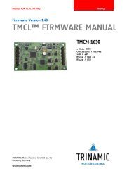
MODULE FOR STEPPER MOTORS MODULE<br />
V 1.03<br />
HARDWARE MANUAL<br />
+ + <strong>TMCM</strong>-<strong>1630</strong><br />
+ +<br />
TRINAMIC Motion Control GmbH & Co. KG<br />
Hamburg, Germany<br />
www.trinamic.com<br />
1-Axis BLDC<br />
Controller / Driver<br />
plug-in module<br />
10A / 48V DC<br />
RS232 / CAN or<br />
RS485 / USB
<strong>TMCM</strong>-<strong>1630</strong> <strong>Hardware</strong> <strong>Manual</strong> (Rev. 1.03 / 2012-JUL-03) 2<br />
Table of contents<br />
1 Life support policy ....................................................................................................................................................... 3<br />
2 Features ........................................................................................................................................................................... 4<br />
3 Order codes .................................................................................................................................................................... 5<br />
4 Mechanical and electrical interfacing ..................................................................................................................... 6<br />
4.1 Dimensions of the module ............................................................................................................................... 6<br />
5 Connectors ...................................................................................................................................................................... 7<br />
5.1 Motor and power connector ............................................................................................................................ 9<br />
5.1.1 Power supply requirements ....................................................................................................................... 9<br />
5.2 Communication, GPIO, and encoder connector........................................................................................ 10<br />
5.2.1 Reset the module to factory defaults .................................................................................................... 10<br />
5.2.2 Inputs .............................................................................................................................................................. 11<br />
5.2.3 Open drain outputs ..................................................................................................................................... 12<br />
5.2.4 Encoder ........................................................................................................................................................... 13<br />
6 LEDs ................................................................................................................................................................................ 14<br />
7 Operational ratings .................................................................................................................................................... 15<br />
8 Functional description .............................................................................................................................................. 16<br />
8.1 System architecture ........................................................................................................................................... 16<br />
8.1.1 Microcontroller ............................................................................................................................................. 16<br />
8.1.2 TMC603A pre-driver ..................................................................................................................................... 16<br />
8.1.3 hallFX - hall sensor feedback ............................................................................................................... 17<br />
9 Revision history .......................................................................................................................................................... 18<br />
9.1 Document revision ............................................................................................................................................ 18<br />
9.2 <strong>Hardware</strong> revision ............................................................................................................................................. 18<br />
10 References..................................................................................................................................................................... 18<br />
www.trinamic.com
<strong>TMCM</strong>-<strong>1630</strong> <strong>Hardware</strong> <strong>Manual</strong> (Rev. 1.03 / 2012-JUL-03) 3<br />
1 Life support policy<br />
TRINAMIC Motion Control GmbH & Co. KG does not<br />
authorize or warrant any of its products for use in life<br />
support systems, without the specific written consent of<br />
TRINAMIC Motion Control GmbH & Co. KG.<br />
Life support systems are equipment intended to support or<br />
sustain life, and whose failure to perform, when properly<br />
used in accordance with instructions provided, can be<br />
reasonably expected to result in personal injury or death.<br />
© TRINAMIC Motion Control GmbH & Co. KG 2012<br />
Information given in this data sheet is believed to be<br />
accurate and reliable. However neither responsibility is<br />
assumed for the consequences of its use nor for any<br />
infringement of patents or other rights of third parties,<br />
which may result from its use.<br />
Specifications are subject to change without notice.<br />
www.trinamic.com
<strong>TMCM</strong>-<strong>1630</strong> <strong>Hardware</strong> <strong>Manual</strong> (Rev. 1.03 / 2012-JUL-03) 4<br />
2 Features<br />
The <strong>TMCM</strong>-<strong>1630</strong> is a highly integrated single axis BLDC servo controller module with several interfaceoptions.<br />
The highly integrated module (size: 50mm x 92.5 mm) has been designed in order to be plugged<br />
onto a baseboard. It integrates velocity and position control and offers hall sensor and incremental encoder<br />
(a/b/n) inputs. The module can be used in stand alone operation or remote controlled.<br />
Applications<br />
Demanding single and multi-axis BLDC motor solutions<br />
Electrical data<br />
Supply voltage: +24V DC or +48V DC nominal (+12… +55V DC max.)<br />
Motor current: up to 10A RMS (programmable) peak<br />
Integrated motion controller<br />
High performance ARM Cortex-M3 microcontroller for system control and communication protocol<br />
handling<br />
Integrated motor driver<br />
High performance integrated pre-driver (TMC603A)<br />
Support for sensorless back EMF commutation (hallFX)<br />
High-efficient operation, low power dissipation (MOSFETs with low R DS(ON))<br />
Dynamic current control<br />
Integrated protection<br />
On the fly alteration of motion parameters (e.g. position, velocity, acceleration)<br />
Interfaces<br />
Two standard assembly options:<br />
RS232 and CAN (2.0B up to 1Mbit/s)<br />
RS485 and USB (High-speed 12Mbit/s)<br />
2 analogue and 2 digital inputs<br />
3 open drain outputs<br />
Motor type<br />
Block commutated 3 phase BLDC motors with optional hall sensors / optional encoder<br />
Motor power from a few Watts to nearly 500W<br />
Motor velocity up to 100,000 RPM (electrical field)<br />
Common supply voltages of 12V DC, 24V DC, 36V DC and 48V DC supported<br />
Coil current up to 10A peak<br />
Software<br />
TMCL stand-alone operation or remote controlled operation<br />
TMCL program memory (non volatile) for up to 2048 TMCL commands<br />
TMCL PC-based application development software TMCL-IDE and TMCL-BLDC available for free<br />
CANopen ready: CiA 301 + CiA 402 (homing mode, profile position mode and velocity mode) under<br />
development<br />
Other<br />
Two double-row 2.54mm connectors<br />
ROHS compliant<br />
Size: 50x92.5mm²<br />
Please see separate TMCL and CANopen Firmware <strong>Manual</strong> (in preparation) for additional information<br />
www.trinamic.com
<strong>TMCM</strong>-<strong>1630</strong> <strong>Hardware</strong> <strong>Manual</strong> (Rev. 1.03 / 2012-JUL-03) 5<br />
3 Order codes<br />
Order code Description Dimensions [mm]<br />
<strong>TMCM</strong>-<strong>1630</strong>-4U-TMCL Single axis BLDC plug-in servo controller module 50 x 92.5 x 14*<br />
with RS485 interface, USB interface and TMCL<br />
firmware<br />
<strong>TMCM</strong>-<strong>1630</strong>-2C-CANopen Single axis BLDC plug-in servo controller module 50 x 92.5 x 14*<br />
with RS232 interface, CAN interface, and CANopen<br />
firmware<br />
<strong>TMCM</strong>-<strong>1630</strong>-2C-TMCL Single axis BLDC plug-in servo controller module 50 x 92.5 x 14*<br />
with RS232 interface, CAN interface, and TMCL<br />
firmware<br />
* Module height (14mm) including connectors<br />
Table 3.1: Order codes<br />
www.trinamic.com
<strong>TMCM</strong>-<strong>1630</strong> <strong>Hardware</strong> <strong>Manual</strong> (Rev. 1.03 / 2012-JUL-03) 6<br />
4 Mechanical and electrical interfacing<br />
4.1 Dimensions of the module<br />
The module has a size of 92.5mm x 50mm. It offers four mounting holes (diameter: 3.2mm). Maximum<br />
overall height of the module including connectors: approx. 14mm.<br />
46<br />
4<br />
4 x 3.2<br />
Figure 4.1: Size of module<br />
www.trinamic.com<br />
92.5<br />
88.5<br />
4<br />
50
<strong>TMCM</strong>-<strong>1630</strong> <strong>Hardware</strong> <strong>Manual</strong> (Rev. 1.03 / 2012-JUL-03) 7<br />
5 Connectors<br />
The module offers two double row 2.54mm pitch standard connectors, one at each end of the board.<br />
1<br />
3<br />
5<br />
7<br />
9<br />
11<br />
13<br />
15<br />
17<br />
19<br />
21<br />
23<br />
25<br />
+5V<br />
Torque<br />
Dir_IN<br />
Stop_IN<br />
LED_Curlim<br />
GND<br />
Enc_A+<br />
Enc_B+<br />
Enc_N+<br />
CANL/USBD-<br />
CANH/USBD+<br />
USB_+VB<br />
GND<br />
Figure 5.1: Connectors<br />
www.trinamic.com<br />
2<br />
4<br />
6<br />
8<br />
10<br />
12<br />
14<br />
16<br />
18<br />
20<br />
22<br />
24<br />
26<br />
Velocity<br />
GND<br />
Tacho<br />
LED_Temp<br />
+5V<br />
GND<br />
Enc_A-<br />
Enc_B-<br />
Enc_N-<br />
RXD/485-<br />
TXD/485+<br />
n.c.<br />
GND<br />
Domain Connector type Mating connector type<br />
I/Os, interfaces, TSM-113-03-L-DV-K-A, 2x13 poles, double SSW, SSQ, SSM, BSW, ESW, ESQ, BCS, SLW,<br />
encoder row, 2.54mm pitch, SMD vertical, Samtec CES, HLE , IDSS and IDSD series, Samtec<br />
Power, hallFX, TSM-113-03-L-DV-K-A, 2x13 poles, double SSW, SSQ, SSM, BSW, ESW, ESQ, BCS, SLW,<br />
motor<br />
row, 2.54mm pitch, SMD vertical, Samtec CES, HLE , IDSS and IDSD series, Samtec<br />
Table 5.1: Connector type and mating connector of the <strong>TMCM</strong>-<strong>1630</strong><br />
Since the two connectors of the <strong>TMCM</strong>-<strong>1630</strong> are similar be careful not to plug-in the module the other<br />
way round. Also, be sure to place the connectors exactly to their mating opponents. Not following<br />
these guidelines might cause permanent damage to the module when turning power supply on.<br />
26<br />
24<br />
22<br />
20<br />
18<br />
16<br />
14<br />
12<br />
10<br />
8<br />
6<br />
4<br />
2<br />
Hall2<br />
Hall3<br />
GND<br />
GND<br />
GND<br />
+VM<br />
+VM<br />
U<br />
U<br />
V<br />
V<br />
W<br />
W<br />
25<br />
23<br />
21<br />
19<br />
17<br />
15<br />
13<br />
11<br />
9<br />
7<br />
5<br />
3<br />
1<br />
Hall1<br />
+5V<br />
GND<br />
GND<br />
GND<br />
+VM<br />
+VM<br />
U<br />
U<br />
V<br />
V<br />
W<br />
W
<strong>TMCM</strong>-<strong>1630</strong> <strong>Hardware</strong> <strong>Manual</strong> (Rev. 1.03 / 2012-JUL-03) 8<br />
Especially for higher motor currents the module offers an assembly option for a detachable screw connector<br />
which will be assembled on the top side of the board. The 5 pin connector offers power supply (+VM and<br />
GND) and motor coil (U, V, W) connections:<br />
Figure 5.2: Additional detachable screw connector as assembly option<br />
The signals are connected 1:1 to the signals with the same label on the two-row motor and power<br />
connector header on the bottom side of the board.<br />
Connector type assembled on board Mating connector type<br />
RIA AKL 330-05 5pin, 5.0mm pitch connector 1x RIA AKL 349-05 5pin, 5.0mm pitch screw connector<br />
or<br />
1x RIA AKL 349-02 2pin, 5.0mm pitch screw connector<br />
for power supply (+VM and GND) and<br />
1x RIA AKL 349-03 3pin 5.0mm pitch screw connector for<br />
motor coil connection (U, V, W)<br />
Table 5.2: Connector type and mating connector of the detachable screw connector<br />
www.trinamic.com<br />
W<br />
V<br />
U<br />
+VM<br />
GND
<strong>TMCM</strong>-<strong>1630</strong> <strong>Hardware</strong> <strong>Manual</strong> (Rev. 1.03 / 2012-JUL-03) 9<br />
5.1 Motor and power connector<br />
A double row 26 pin header with 2.54mm pitch is used for connecting all motor related signals and module<br />
power supply.<br />
Pin Label Description Pin Label Description<br />
1 W Motor coil W 2 W Motor coil W<br />
3 W Motor coil W 4 W Motor coil W<br />
5 V Motor coil V 6 V Motor coil V<br />
7 V Motor coil V 8 V Motor coil V<br />
9 U Motor coil U 10 U Motor coil U<br />
11 U Motor coil U 12 U Motor coil U<br />
13 VM Module driver supply voltage 14 VM Module driver supply voltage<br />
15 VM Module driver supply voltage 16 VM Module driver supply voltage<br />
17 GND<br />
Module ground (power supply<br />
and signal ground)<br />
18 GND<br />
Module ground (power supply<br />
and signal ground)<br />
19 GND<br />
Module ground (power supply<br />
and signal ground)<br />
20 GND<br />
Module ground (power supply<br />
and signal ground)<br />
21 GND<br />
Module ground (power supply<br />
and signal ground)<br />
+5V output (100mA max.) for<br />
22 GND<br />
Module ground (power supply<br />
and signal ground)<br />
23 +5V encoder and/or hall sensor<br />
supply<br />
24 HALL3 Hall sensor 3 signal input<br />
25 HALL1 Hall sensor 1 signal input 26 HALL2 Hall sensor 2 signal input<br />
Table 5.3: Connector for motor related signals and power supply<br />
5.1.1 Power supply requirements<br />
The power supply should be designed in a way, that it supplies the nominal motor voltage at the desired<br />
maximum motor current. In no case shall the supply voltage exceed the upper or lower voltage limits. To be<br />
able to cope with high voltage spikes which might be caused by energy fed back from the motor during<br />
deceleration, a sufficient power supply capacitor should be added on the baseboard closed to the module.<br />
Depending on the motor and expected motor current please use a 4700µF or larger capacitor with suitable<br />
voltage rating. Additionally, a suitable suppressor (zener-) diode might be useful.<br />
www.trinamic.com
<strong>TMCM</strong>-<strong>1630</strong> <strong>Hardware</strong> <strong>Manual</strong> (Rev. 1.03 / 2012-JUL-03) 10<br />
5.2 Communication, GPIO, and encoder connector<br />
A double row 26 pin header with 2.54mm pitch is used for connecting all communication and GPIO signals.<br />
Pin Label Description Pin Label Description<br />
1 +5V<br />
3 Torque<br />
5 Dir_IN<br />
7 Stop_IN<br />
9 LED-Curlim<br />
www.trinamic.com<br />
5V analog reference as used by<br />
the internal DAC.<br />
Max. load 0.5mA<br />
Used for max. motor current /<br />
torque control in stand alone<br />
operation by supplying external<br />
0-10V signal<br />
5V TTL input. Tie to GND to<br />
inverse motor direction, leave<br />
open or tie to 5V otherwise.<br />
Emergency stop. Tie this pin to<br />
GND to stop the motor (same as<br />
the Motor Off switch on PCB).<br />
The motor can be restarted via<br />
the interface, or by cycling the<br />
power supply<br />
High, when module goes into<br />
current limiting mode<br />
2 Velocity<br />
4 GND<br />
6 Tacho<br />
8 LED-Temp<br />
10 +5V<br />
Used for velocity control in<br />
stand alone operation by<br />
supplying external 0 – 10V<br />
signal<br />
Module ground (power supply<br />
and signal ground)<br />
This pin outputs a tacho<br />
impulse, i.e. toggles on each<br />
hall sensor change<br />
5V TTL output: Toggling with<br />
3Hz when temperature prewarning<br />
threshold is exceeded,<br />
high when module shut down<br />
due to overtemperature<br />
5V output as reference for<br />
external purpose<br />
11 GND GND reference 12 GND GND reference<br />
13 Enc_A+ Encoder A+ channel 14 Enc_A- Encoder A- channel<br />
15 Enc_B+ Encoder B+ channel 16 Enc_B- Encoder B- channel<br />
17 Enc_N+ Encoder N+ channel 18 Enc_N- Encoder N- channel<br />
19 CANL/USBD-<br />
CAN low /<br />
USB D- bus line<br />
20 RXD/<br />
485-<br />
RXD signal for RS232 /<br />
inverting signal for RS485<br />
21 CANH/USBD+<br />
CAN high /<br />
USB D+ bus line<br />
22 TXD/<br />
485+<br />
TXD signal for RS232 /<br />
non inverting signal for RS485<br />
23 USB_+VB<br />
Use to detect availability of<br />
attached host system (e.g. PC)<br />
24 n.c.<br />
25 GND GND reference 26 GND GND reference<br />
Table 5.4: Connector for communication and GPIOs<br />
5.2.1 Reset the module to factory defaults<br />
Interface Description<br />
RS232 Short RxD and TxD for resetting the module.<br />
USB Use your USB interface for resetting the module<br />
with the functions of TMCL-IDE. Please refer to the<br />
TMCL Firmware <strong>Manual</strong>.<br />
Table 5.5: Reset the module to factory defaults
<strong>TMCM</strong>-<strong>1630</strong> <strong>Hardware</strong> <strong>Manual</strong> (Rev. 1.03 / 2012-JUL-03) 11<br />
5.2.2 Inputs<br />
The <strong>TMCM</strong>-<strong>1630</strong> offers two analogue and two digital inputs.<br />
Pin Label analogue/digital Description<br />
2 Velocity analogue<br />
3 Torque analogue<br />
5 Dir_IN digital<br />
7 Stop_IN digital<br />
+3.3V<br />
GND<br />
www.trinamic.com<br />
+3.3V<br />
GND<br />
Figure 5.3: Internal circuit of analogue and digital inputs<br />
+3.3V<br />
GND<br />
Used for velocity control in stand alone operation by<br />
supplying external 0 – 10V signal<br />
Used for max. motor current / torque control in stand alone<br />
operation by supplying external 0 – 10V signal<br />
Direction input (+5V TTL compatible). Tie to GND to inverse motor<br />
direction, leave open or tie to +5V otherwise.<br />
Emergency stop. Tie this pin to GND to stop the motor. The motor<br />
can be restarted via the interface, or by cycling the power supply<br />
+3.3V<br />
GND<br />
GND<br />
19k1/1%<br />
GND<br />
19k1/1%<br />
39k<br />
39k<br />
10k/1%<br />
10k/1%<br />
100pF/50V<br />
GND<br />
100pF/50V<br />
GND<br />
100pF/50V<br />
GND<br />
100pF/50V<br />
GND<br />
Header<br />
Velocity<br />
Torque<br />
DIR_IN<br />
STOP_IN
<strong>TMCM</strong>-<strong>1630</strong> <strong>Hardware</strong> <strong>Manual</strong> (Rev. 1.03 / 2012-JUL-03) 12<br />
5.2.3 Open drain outputs<br />
The module offers three open drain outputs. Two of them (LED-Temp and LED-Curlim) power on-board LEDs,<br />
also. Please refer to paragraph 6 for more information about the LEDs.<br />
Pin Label Description<br />
6 Tacho<br />
This pin outputs a tacho impulse, i.e. toggles on each hall sensor<br />
change<br />
+5V TTL output: Toggling with 3Hz when temperature pre-warning<br />
8 LED-Temp threshold is exceeded, low when module shut down due to<br />
overtemperature<br />
9 LED-Curlim Low when module goes into current limiting mode<br />
Table 5.6: Outputs of the <strong>TMCM</strong>-<strong>1630</strong><br />
GND<br />
10k/1%<br />
www.trinamic.com<br />
220R<br />
GND<br />
Figure 5.4: Internal circuit of the outputs<br />
+VM +5V<br />
1kOO/1%<br />
Header<br />
Tacho<br />
LED-Temp<br />
LED-Curlim
<strong>TMCM</strong>-<strong>1630</strong> <strong>Hardware</strong> <strong>Manual</strong> (Rev. 1.03 / 2012-JUL-03) 13<br />
5.2.4 Encoder<br />
Pin Label Description<br />
13 Enc_A+ Encoder A+ channel<br />
14 Enc_A- Encoder A- channel<br />
15 Enc_B+ Encoder B+ channel<br />
16 Enc_B- Encoder B- channel<br />
17 Enc_N+ Encoder N+ channel<br />
18 Enc_N- Encoder N- channel<br />
Table 5.7: Encoder channels of <strong>TMCM</strong>-<strong>1630</strong><br />
A+<br />
A-<br />
B+<br />
B-<br />
N+<br />
N-<br />
3k30/1%<br />
470R/5%<br />
47k/5%<br />
www.trinamic.com<br />
470R/5%<br />
47k/5%<br />
470R/5%<br />
47k/5%<br />
2k2/1%<br />
+5V<br />
GND<br />
120R/5%<br />
120R/5%<br />
Figure 5.5: Internal circuit of the encoder channels<br />
120R/5%<br />
Differential<br />
Line<br />
Recever<br />
ENC_A<br />
ENC_B<br />
ENC_N
<strong>TMCM</strong>-<strong>1630</strong> <strong>Hardware</strong> <strong>Manual</strong> (Rev. 1.03 / 2012-JUL-03) 14<br />
6 LEDs<br />
The <strong>TMCM</strong>-<strong>1630</strong> module has 4 on-board LEDs for power, error indication, current overload, and temperature<br />
warning. The LEDs are placed on the back of the module. You can plug the module on its baseboard and<br />
take a look at the LEDs on the backside of the module.<br />
Figure 6.1: On-board LEDs<br />
www.trinamic.com<br />
Power<br />
Error<br />
Current overload<br />
Temperature warning<br />
LED Color Description<br />
Power green LED is ON, if the on-board +5V are available<br />
Error red ON in case of error<br />
Current overload<br />
Temperature warning<br />
red<br />
red<br />
Blink<br />
ON/Flicker<br />
Table 6.1: LEDs signals and their meaning<br />
The current limit LED blinks upon under<br />
voltage switch off<br />
Motor PWM is reduced due to exceeding the<br />
set motor current limit<br />
Blink The power stage on the module has exceeded<br />
a critical temperature of 100°C (Pre-warning)<br />
ON The power stage on the module has exceeded<br />
the critical temperature of 125°C. The motor<br />
becomes switched off, until temperature falls<br />
below 115°C. The measurement is correct to<br />
about +/-10°C
<strong>TMCM</strong>-<strong>1630</strong> <strong>Hardware</strong> <strong>Manual</strong> (Rev. 1.03 / 2012-JUL-03) 15<br />
7 Operational ratings<br />
The operational ratings show the intended/the characteristic range for the values and should be used as<br />
design values. An operation within the limiting values is possible, but shall not be used for extended<br />
periods, because the unit life time may be shortened. In no case shall the limiting values be exceeded.<br />
Symbol Parameter Min Typ Max Unit<br />
V S Power supply voltage for operation 12 24, 48 55 V<br />
I S Power supply current 0.04 I MOT A<br />
P ID Module idle power consumption 1.2 W<br />
V 5<br />
www.trinamic.com<br />
5 Volt (+-8%) output external load (hall sensors plus<br />
other load)<br />
100 mA<br />
I MC Continuous Motor current at V MF 0 – 8 10 A<br />
I MP Short time Motor current in acceleration periods 0 – 10 A<br />
V I Logic input voltage on digital / hall sensor inputs -0.3 V CC+<br />
I O Sink current on digital outputs (open-drain outputs) 1 A<br />
V IA Analog input voltage -24 0 – 10 24 V<br />
f CHOP Chopper frequency 20 kHz<br />
E x Exactness of voltage and current measurement -8 +8 %<br />
T SL Motor output slope (U, V, W) 100 ns<br />
T O Environment temperature operating -25 +70 °C<br />
T OF<br />
T board<br />
Environment temperature for operation at full specified<br />
current (air flow might required, depending upon motor<br />
/ voltage)<br />
Temperature of the module, as measured by the<br />
integrated sensor.<br />
Table 7.1: Operational ratings<br />
0.3<br />
-25 +60 °C<br />
V<br />
<strong>TMCM</strong>-<strong>1630</strong> <strong>Hardware</strong> <strong>Manual</strong> (Rev. 1.03 / 2012-JUL-03) 16<br />
8 Functional description<br />
In figure 8.1 the main parts of the <strong>TMCM</strong>-<strong>1630</strong> module are shown. The module mainly consists of the<br />
Cortex-M3 CPU, TRINAMICs highly integrated TMC603 BLDC motor pre-driver, the MOSFET driver stage,<br />
different interfaces (depends up-on which option you have chosen), the inputs, and the outputs (open<br />
drain).<br />
RS232 or RS485<br />
USB or CAN<br />
Analogue Inputs:<br />
Velocity,<br />
Torque<br />
Digital Inputs:<br />
Dir_IN,<br />
Stop_IN<br />
Open drain outputs:<br />
Tacho,<br />
LED_Temp,<br />
LED_Curlim<br />
12… 55V DC<br />
www.trinamic.com<br />
2<br />
2<br />
3<br />
5V<br />
3.3V<br />
Cortex_M3<br />
CPU<br />
hall FX<br />
EEPROM<br />
TMC603<br />
BLDC motor<br />
driver<br />
ABN<br />
Figure 8.1: Main parts of the <strong>TMCM</strong>-<strong>1630</strong><br />
8.1 System architecture<br />
MOSFET<br />
driver<br />
stage<br />
<strong>TMCM</strong>-<strong>1630</strong><br />
Hall sensor<br />
feedback<br />
optional<br />
BLDC Motor<br />
encoder<br />
feedback<br />
The <strong>TMCM</strong>-<strong>1630</strong> integrates a microcontroller with the TMCL Firmware or CANopen. The motion control realtime<br />
tasks are realized by the TMC603A.<br />
8.1.1 Microcontroller<br />
On this module, the ARM Cortex-M3 CPU 32-bit processor is used to run the TMCL operating system and<br />
to control the TMC603A. The flash memory of the microcontroller holds the TMCL operating system. The<br />
EEPROM memory is used to permanently store configuration data. The microcontroller runs the TMCL or<br />
CANopen operating system which makes it possible to execute commands that are sent to the module from<br />
the host via the interface. The microcontroller interprets the commands and controls the TMC603A.<br />
The TMCL operating system can be updated via the host interface. Please use the latest version of the<br />
TMCL-IDE to do this.<br />
8.1.2 TMC603A pre-driver<br />
The TMC603A is a three phase motor driver for highly compact and energy efficient drive solutions. It<br />
contains all power and analog circuitry required for a high performance BLDC motor system. The TMC603A is<br />
designed to provide the frontend for a microcontroller doing motor commutation and control algorithms.<br />
Integrated hallFX (pat.) allows for sensorless commutation. Protection and diagnostic features as well as a<br />
step down switching regulator reduce system cost and increase reliability.<br />
optional
<strong>TMCM</strong>-<strong>1630</strong> <strong>Hardware</strong> <strong>Manual</strong> (Rev. 1.03 / 2012-JUL-03) 17<br />
8.1.3 hallFX - hall sensor feedback<br />
hallFX provides emulated hall sensor signals. The emulated hall sensor signals are available without a<br />
phase shift and there is no error-prone PLL necessary, like with many other systems, nor is the knowledge<br />
of special motor parameters required. Since it is based on the motors’ back-EMF, a minimum motor velocity<br />
is required to get a valid signal. Therefore, the motor needs to be started without feedback, until the<br />
velocity is high enough to generate a reliable hallFX signal.<br />
Please refer to the <strong>TMCM</strong>-<strong>1630</strong> Firmware <strong>Manual</strong> for further information about using hallFX.<br />
Low pass LPU<br />
BM1<br />
ULP<br />
E1<br />
H1<br />
BM2<br />
BM3<br />
Switch Cap filters<br />
Low pass LPV<br />
Low pass LPW<br />
Figure 8.2: hallFX block diagram and timing<br />
A switched capacitor filter for each coil supplies the measured effective coil voltages. Its filter frequency can<br />
be adapted to the chopper frequency and the desired maximum motor velocity. An induction pulse<br />
suppressor unit gates the commutation spikes which result from the inductive behavior of the motor coils<br />
after switching off the current. The gating time can be adapted by an external capacitor to fit the motor<br />
inductivity and its (maximum) velocity.<br />
www.trinamic.com<br />
D<br />
SC_CLK<br />
30k<br />
A<br />
FILT3<br />
FILT2<br />
FILT1<br />
Position signal<br />
generation (PSG)<br />
VLP<br />
30k<br />
WLP<br />
A<br />
30k<br />
A<br />
PSG<br />
E2<br />
E3<br />
ENRS_TEST<br />
Induction pulse<br />
supressor (IPS)<br />
IPS<br />
D<br />
A<br />
SP_SUP<br />
CSUP<br />
D H2<br />
D H3<br />
U<br />
V<br />
W<br />
E1<br />
E2<br />
E3<br />
H1<br />
H2<br />
H3
<strong>TMCM</strong>-<strong>1630</strong> <strong>Hardware</strong> <strong>Manual</strong> (Rev. 1.03 / 2012-JUL-03) 18<br />
9 Revision history<br />
9.1 Document revision<br />
Version Date Author Description<br />
1.00 2011-JUN-02 SD Initial version<br />
1.01 2011-NOV-07 SD Minor changes<br />
1.02 2012-JUN-11 SD Hall signal description (connector) corrected.<br />
1.03 2012-JUL-03 GE<br />
Assembly option for 5pin detachable screw connector for power and<br />
motor coil connection on top side of module added.<br />
Table 9.1: Document revision<br />
9.2 <strong>Hardware</strong> revision<br />
Version Date Description<br />
V1.0 2011-JAN-19 First version<br />
Table 9.2: <strong>Hardware</strong> revision<br />
10 References<br />
[<strong>TMCM</strong>-<strong>1630</strong>] <strong>TMCM</strong>-<strong>1630</strong> TMCL Firmware <strong>Manual</strong><br />
[BB-<strong>1630</strong>] BB-<strong>1630</strong> <strong>Hardware</strong> <strong>Manual</strong><br />
[TMCL-IDE] TMCL-IDE User <strong>Manual</strong><br />
[TMCL-BLDC] TMCL-BLDC User <strong>Manual</strong><br />
Please refer to www.trinamic.com.<br />
www.trinamic.com


