TMCM-1110 TMCL Firmware Manual - Trinamic
TMCM-1110 TMCL Firmware Manual - Trinamic
TMCM-1110 TMCL Firmware Manual - Trinamic

Create successful ePaper yourself
Turn your PDF publications into a flip-book with our unique Google optimized e-Paper software.
MODULE FOR STEPPER MOTORS MODULE<br />
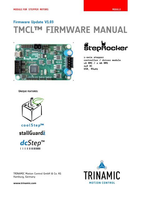
<strong>Firmware</strong> Update V1.03<br />
<strong>TMCL</strong> FIRMWARE MANUAL<br />
+ +<br />
+ +<br />
UNIQUE FEATURES:<br />
TRINAMIC Motion Control GmbH & Co. KG<br />
Hamburg, Germany<br />
www.trinamic.com<br />
1-axis stepper<br />
controller / driver module<br />
1A RMS / 2.8A RMS<br />
24V DC<br />
USB, RS485
<strong>TMCM</strong>-<strong>1110</strong> <strong>TMCL</strong> <strong>Firmware</strong> V1.03 <strong>Manual</strong> (Ref. 1.07 / 2012-APR-11) 2<br />
Table of Contents<br />
1 Features ........................................................................................................................................................................... 4<br />
2 Overview ......................................................................................................................................................................... 5<br />
3 Putting the Module into Operation ......................................................................................................................... 6<br />
3.1 Basic Set-up ........................................................................................................................................................... 7<br />
3.1.1 Connecting the Module ............................................................................................................................... 7<br />
3.1.2 Start the <strong>TMCL</strong>-IDE Software Development Environment ................................................................. 9<br />
3.1.3 Using <strong>TMCL</strong> Direct Mode ........................................................................................................................ 10<br />
3.1.4 Important Motor Settings ......................................................................................................................... 11<br />
4 <strong>TMCL</strong> and <strong>TMCL</strong>-IDE ................................................................................................................................................ 13<br />
4.1 Binary Command Format ................................................................................................................................ 13<br />
4.2 Reply Format ....................................................................................................................................................... 14<br />
4.2.1 Status Codes ................................................................................................................................................. 14<br />
4.3 Standalone Applications .................................................................................................................................. 14<br />
4.3.1 Testing with a Simple <strong>TMCL</strong> Program ............................................................................................... 15<br />
4.4 <strong>TMCL</strong> Command Overview .......................................................................................................................... 15<br />
4.4.1 <strong>TMCL</strong> Commands ..................................................................................................................................... 15<br />
4.4.2 Commands Listed According to Subject Area ..................................................................................... 16<br />
4.5 Commands ........................................................................................................................................................... 20<br />
4.5.1 ROR (rotate right)......................................................................................................................................... 20<br />
4.5.2 ROL (rotate left) ............................................................................................................................................ 21<br />
4.5.3 MST (motor stop) ......................................................................................................................................... 22<br />
4.5.4 MVP (move to position) ............................................................................................................................. 23<br />
4.5.5 SAP (set axis parameter) ........................................................................................................................... 25<br />
4.5.6 GAP (get axis parameter) ........................................................................................................................... 26<br />
4.5.7 STAP (store axis parameter) ..................................................................................................................... 27<br />
4.5.8 RSAP (restore axis parameter) ................................................................................................................. 28<br />
4.5.9 SGP (set global parameter) ....................................................................................................................... 29<br />
4.5.10 GGP (get global parameter) ...................................................................................................................... 30<br />
4.5.11 STGP (store global parameter) ................................................................................................................. 31<br />
4.5.12 RSGP (restore global parameter) ............................................................................................................. 32<br />
4.5.13 RFS (reference search) ................................................................................................................................ 33<br />
4.5.14 SIO (set output) ........................................................................................................................................... 34<br />
4.5.15 GIO (get input/output) ............................................................................................................................... 35<br />
4.5.16 CALC (calculate) ............................................................................................................................................ 37<br />
4.5.17 COMP (compare) ........................................................................................................................................... 38<br />
4.5.18 JC (jump conditional).................................................................................................................................. 39<br />
4.5.19 JA (jump always).......................................................................................................................................... 40<br />
4.5.20 CSUB (call subroutine) ................................................................................................................................ 41<br />
4.5.21 RSUB (return from subroutine) ................................................................................................................ 42<br />
4.5.22 WAIT (wait for an event to occur) ......................................................................................................... 43<br />
4.5.23 STOP (stop <strong>TMCL</strong> program execution) ............................................................................................... 44<br />
4.5.24 SCO (set coordinate) ................................................................................................................................... 45<br />
4.5.25 GCO (get coordinate) .................................................................................................................................. 46<br />
4.5.26 CCO (capture coordinate) ........................................................................................................................... 47<br />
4.5.27 ACO (accu to coordinate)........................................................................................................................... 48<br />
4.5.28 CALCX (calculate using the X register) .................................................................................................. 49<br />
4.5.29 AAP (accumulator to axis parameter) .................................................................................................... 50<br />
4.5.30 AGP (accumulator to global parameter) ............................................................................................... 51<br />
4.5.31 CLE (clear error flags) ................................................................................................................................. 52<br />
4.5.32 VECT (set interrupt vector) ........................................................................................................................ 53<br />
4.5.33 EI (enable interrupt) ................................................................................................................................... 54<br />
4.5.34 DI (disable interrupt) .................................................................................................................................. 55<br />
4.5.35 RETI (return from interrupt) ..................................................................................................................... 56<br />
4.5.36 Customer Specific <strong>TMCL</strong> Command Extension (UF0… UF7 - User Function)............................ 56<br />
4.5.37 Request Target Position Reached Event ............................................................................................... 57<br />
4.5.38 <strong>TMCL</strong> Control Functions ......................................................................................................................... 58<br />
www.trinamic.com
<strong>TMCM</strong>-<strong>1110</strong> <strong>TMCL</strong> <strong>Firmware</strong> V1.03 <strong>Manual</strong> (Ref. 1.07 / 2012-APR-11) 3<br />
5 Axis Parameters........................................................................................................................................................... 59<br />
5.1 stallGuard2 Related Parameters ................................................................................................................. 65<br />
5.2 coolStep Related Parameters ..................................................................................................................... 67<br />
5.3 Reference Search ................................................................................................................................................ 69<br />
5.3.1 Reference Search Modes (Axis Parameter 193) ................................................................................... 70<br />
5.4 Encoder ................................................................................................................................................................. 72<br />
5.4.1 Changing the Prescaler Value of an Encoder ...................................................................................... 72<br />
5.5 Calculation: Velocity and Acceleration vs. Microstep- and Fullstep-Frequency ............................... 73<br />
5.5.1 Microstep Frequency ................................................................................................................................... 74<br />
5.5.2 Fullstep Frequency ...................................................................................................................................... 74<br />
6 Global Parameters ...................................................................................................................................................... 76<br />
6.1 Bank 0 ................................................................................................................................................................... 76<br />
6.2 Bank 1 ................................................................................................................................................................... 78<br />
6.3 Bank 2 ................................................................................................................................................................... 78<br />
6.4 Bank 3 ................................................................................................................................................................... 79<br />
7 <strong>TMCL</strong> Programming Techniques and Structure .............................................................................................. 80<br />
7.1 Initialization ........................................................................................................................................................ 80<br />
7.2 Main Loop ............................................................................................................................................................ 80<br />
7.3 Using Symbolic Constants............................................................................................................................... 80<br />
7.4 Using Variables ................................................................................................................................................... 81<br />
7.5 Using Subroutines ............................................................................................................................................. 81<br />
7.6 Mixing Direct Mode and Standalone Mode ................................................................................................ 82<br />
8 Life Support Policy ..................................................................................................................................................... 83<br />
9 Revision History .......................................................................................................................................................... 84<br />
9.1 <strong>Firmware</strong> Revision ............................................................................................................................................. 84<br />
9.2 Document Revision ........................................................................................................................................... 84<br />
10 References..................................................................................................................................................................... 85<br />
www.trinamic.com
<strong>TMCM</strong>-<strong>1110</strong> <strong>TMCL</strong> <strong>Firmware</strong> V1.03 <strong>Manual</strong> (Ref. 1.07 / 2012-APR-11) 4<br />
1 Features<br />
The <strong>TMCM</strong>-<strong>1110</strong> stepRocker is a single axis motor controller/driver board for 2-phase bipolar stepper motors.<br />
It features the TRINAMIC controller/driver chain consisting of TMC429 and TMC262 in combination with a<br />
Samsung S3FN41F processor. The Module is intended to be a fully functional development platform. A<br />
stepRocker can be extended to a full 3-axes system using two additional boards, because the <strong>TMCM</strong>-<strong>1110</strong><br />
stepRocker board can be both, master or slave.<br />
Software wise two different approaches are possible: it is possible to use the stepRocker with the<br />
<strong>Trinamic</strong>MotionControlLanguage <strong>TMCL</strong>. The board comes with the preinstalled firmware. The integrated<br />
development environment <strong>TMCL</strong>-IDE for PC can be downloaded and used free of charge. It is possible to<br />
remote control the stepRocker or to write and download complete command sequences for standalone use.<br />
The alternative is to write the firmware for the microcontroller using downloadable software tools and<br />
motion control libraries (refer to www.motioncontrol-community.org).<br />
Applications<br />
Highly compact single axis stepper motor controller/driver board for 2-phase bipolar stepper motors<br />
2- and 3-axis systems using additional boards as slaves<br />
Electrical data<br />
Supply voltage: +24V DC (+10… +30V DC)<br />
Motor current: up to 1A RMS or 2.8A RMS (can be selected with jumpers)<br />
Mechanical data<br />
Board size: 85mm x 55mm, height 15mm max. without mating connectors<br />
4 mounting holes for M3 screws<br />
Interfaces<br />
RS485 host interface<br />
USB 2.0 host interface (mini-USB connector)<br />
Step/Dir input (TTL level)<br />
Step/Dir outputs (TTL level) for multi axis applications<br />
3 multi-purpose inputs (can be used for ABN-encoder)<br />
2 limit switch inputs per motor<br />
6 multi-purpose I/Os<br />
2 open-drain outputs<br />
µC programming interface SWD (single wire debug / pads on PCB)<br />
Retro-fit option: CAN 2.0B communication interface<br />
Features<br />
TMC429 stepper motor controller IC for on-the-fly alteration of many motion specific parameters<br />
TMC262 advanced stepper motor driver IC with stallGuard2 and coolStep features. Using the<br />
spreadCycle chopper the µstep current sine wave is well formed with smooth zero crossing.<br />
Ready for dcStep<br />
Up to 256 microsteps per fullstep trough mircoPlyer technology<br />
2 x end switch for all three axes.<br />
EEPROM<br />
Software<br />
<strong>TMCL</strong> remote (direct mode) and standalone operation (memory for up to 2048 <strong>TMCL</strong> commands)<br />
Fully supported by <strong>TMCL</strong>-IDE (PC based integrated development environment)<br />
Please note that the <strong>TMCM</strong>-<strong>1110</strong> stepRocker can be used with a special <strong>TMCL</strong> firmware version with its<br />
source codes in order to provide new developments, too. Here is your platform for individual <strong>TMCL</strong><br />
extensions: www.motioncontrol-community.org or www.steprocker.com.<br />
www.trinamic.com
<strong>TMCM</strong>-<strong>1110</strong> <strong>TMCL</strong> <strong>Firmware</strong> V1.03 <strong>Manual</strong> (Ref. 1.07 / 2012-APR-11) 5<br />
2 Overview<br />
The software running on the microprocessor of the <strong>TMCM</strong>-<strong>1110</strong> consists of two parts, a boot loader and the<br />
firmware itself. Whereas the boot loader is installed during production and testing at TRINAMIC and remains<br />
untouched throughout the whole lifetime, the firmware can be updated by the user. New versions can be<br />
downloaded free of charge from the TRINAMIC website (http://www.trinamic.com).<br />
The firmware is related to the standard <strong>TMCL</strong> firmware with regard to protocol and commands.<br />
Corresponding, this module is based on the TMC429 stepper motor controller and the TMC262 power driver<br />
and supports the standard <strong>TMCL</strong> with a special range of values.<br />
The TMC262 is a new energy efficient high current high precision microstepping driver IC for bipolar stepper<br />
motors and offers TRINAMICs patented coolStep feature with its special commands. Please mind this<br />
technical innovation.<br />
All commands and parameters available with this unit are explained on the following pages.<br />
www.trinamic.com
<strong>TMCM</strong>-<strong>1110</strong> <strong>TMCL</strong> <strong>Firmware</strong> V1.03 <strong>Manual</strong> (Ref. 1.07 / 2012-APR-11) 6<br />
3 Putting the Module into Operation<br />
In this chapter you will find basic information for putting your module into operation. This includes a<br />
simple example for a <strong>TMCL</strong> program and a short description of operating the module in direct mode.<br />
The stepRocker is able to control up to three motors. In this chapter it is explained how to start with one<br />
motor (motor number 0), only. If you want to use the module for controlling more motors, refer to the<br />
Hardware <strong>Manual</strong>, please. There you will find information about extensions.<br />
THINGS YOU NEED<br />
- <strong>TMCM</strong>-<strong>1110</strong> with appropriate stepper motor (e.g. QSH4218)<br />
- Interface (RS485 or USB) suitable to your <strong>TMCM</strong>-<strong>1110</strong> module<br />
- Nominal supply voltage +24V DC (+9… +28V DC) for your module<br />
- <strong>TMCL</strong>-IDE program (can be downloaded free of charge from www.trinamic.com. Please refer to the<br />
<strong>TMCL</strong>-IDE User <strong>Manual</strong>, too)<br />
- Appropriate cables – at least for power supply, communication and motor<br />
PRECAUTIONS<br />
Do not mix up connections or short-circuit pins.<br />
Avoid bounding I/O wires with motor power wires.<br />
Do not exceed the maximum power supply of +30V DC!<br />
Do not connect or disconnect the motor while powered on!<br />
START WITH POWER SUPPLY OFF!<br />
USB<br />
RS485<br />
(CAN<br />
optional)<br />
www.trinamic.com<br />
1<br />
1<br />
GPIO<br />
1<br />
Reference<br />
switches<br />
Power<br />
1<br />
14 1<br />
1<br />
Driver<br />
In<br />
Controller<br />
Out 1<br />
1<br />
Controller<br />
Out 2<br />
Figure 3.1: <strong>TMCM</strong>-<strong>1110</strong> stepRocker connectors<br />
1<br />
Motor
<strong>TMCM</strong>-<strong>1110</strong> <strong>TMCL</strong> <strong>Firmware</strong> V1.03 <strong>Manual</strong> (Ref. 1.07 / 2012-APR-11) 7<br />
3.1 Basic Set-up<br />
The following paragraph will guide you through the steps of connecting the unit and making first<br />
movements with the motor.<br />
3.1.1 Connecting the Module<br />
For first steps you will need a power supply and a communication between PC and one of the serial<br />
interfaces of the module (RS485 or USB). If you are interested in detailed pin assignments, please refer to<br />
the <strong>TMCM</strong>-<strong>1110</strong> Hardware <strong>Manual</strong>.<br />
Please note: later on it is perfectly possible to operate the unit as standalone device, using the available<br />
inputs and outputs for control.<br />
3.1.1.1 Communication<br />
Choose your communication interface out of the interfaces: RS485 or USB.<br />
3.1.1.1.1 RS485<br />
Connect the RS485 interface with the appropriate connector (see Figure 3.1)<br />
RS485 as field bus interface normally requires an adapter. From TRINAMIC the USB-2-485 converter between<br />
USB and RS485 is available.<br />
Label Connector type Mating connector type<br />
RS485<br />
3.1.1.1.2 USB<br />
www.trinamic.com<br />
Low profile box header without locking<br />
bar, type 8380, 10 pol., DIN 41651,<br />
2.54mm pitch<br />
Low profile IDC socket connector, 10pol.,<br />
DIN41651, 2.54mm pitch<br />
Before using the USB interface the device driver has to be installed (available on www.trinamic.com).<br />
Label Connector type Mating connector type<br />
Mini-USB connector<br />
Molex 500075-1517 Mini USB Type B<br />
vertical receptacle<br />
Any standard mini-USB plug<br />
3.1.1.2 Motor<br />
The <strong>TMCM</strong>-<strong>1110</strong> controls one 2-phase stepper motor. Connect one coil of the motor to the terminal marked<br />
A0 and A1 and the other coil to the connector marked B0 and B1.<br />
Before connecting a motor please make sure which cable belongs to which coil. Wrong connections may<br />
lead to damage of the driver chips or the motor!<br />
Label Connector type Mating connector type<br />
Motor<br />
Motor 0… 5<br />
A1<br />
A2<br />
B1<br />
B2<br />
M<br />
Figure 3.2: Motor connection<br />
RIA 183-04, 4 pol., 3.5mm pitch,<br />
shrouded header<br />
RIA 169-04, screw type terminal block,<br />
pluggable, centerline 3.5mm pitch
<strong>TMCM</strong>-<strong>1110</strong> <strong>TMCL</strong> <strong>Firmware</strong> V1.03 <strong>Manual</strong> (Ref. 1.07 / 2012-APR-11) 8<br />
3.1.1.3 Power Supply<br />
Connect the power supply with the power supply connector (see Figure 3.1), but start with power supply<br />
OFF.<br />
Take care of the polarity, wrong polarity can destroy the board!<br />
Do not exceed the maximum power supply of +30V DC!<br />
Label Connector type Mating connector type<br />
Power<br />
www.trinamic.com<br />
RIA 220-02, 2 pol., 5.08mm pitch,<br />
shrouded header<br />
3.1.1.4 Reference / Home Switches<br />
Connect the switches with the appropriate connectors if needed.<br />
RIA 249-02, screw type terminal block,<br />
pluggable, centerline 5.08mm pitch<br />
Please refer to the Hardware <strong>Manual</strong> for more information about the reference switch connectors.<br />
Label Connector type Mating connector type<br />
Ref. switches Multi-pin-connector, 7 pol., 2.54mm pitch Female connector with 2.54mm pitch<br />
3.1.1.5 I/Os<br />
Connect inputs and outputs with the appropriate connectors (see Figure 3.1), if you want to use them.<br />
Please refer to the Hardware <strong>Manual</strong> for more information about the I/O connectors.<br />
Label Connector type Mating connector type<br />
GPIO<br />
Multi-pin-connector, 14 pol., 2.54mm<br />
pitch<br />
Female connector with 2.54mm pitch
<strong>TMCM</strong>-<strong>1110</strong> <strong>TMCL</strong> <strong>Firmware</strong> V1.03 <strong>Manual</strong> (Ref. 1.07 / 2012-APR-11) 9<br />
3.1.2 Start the <strong>TMCL</strong>-IDE Software Development Environment<br />
The <strong>TMCL</strong>-IDE is available on www.trinamic.com.<br />
Installing the <strong>TMCL</strong>-IDE:<br />
Make sure the COM port you intend to use is not blocked by another program.<br />
Open <strong>TMCL</strong>-IDE by clicking <strong>TMCL</strong>.exe.<br />
Choose Setup and Options and thereafter the Connection tab.<br />
For RS485 choose COM port and Type with the parameters shown below (baud rate 9600). Click OK.<br />
Please refer to the <strong>TMCL</strong>-IDE User <strong>Manual</strong> for more information about connecting the other interfaces<br />
(www.TRINAMIC.com).<br />
www.trinamic.com
<strong>TMCM</strong>-<strong>1110</strong> <strong>TMCL</strong> <strong>Firmware</strong> V1.03 <strong>Manual</strong> (Ref. 1.07 / 2012-APR-11) 10<br />
3.1.3 Using <strong>TMCL</strong> Direct Mode<br />
Start <strong>TMCL</strong> Direct Mode.<br />
www.trinamic.com<br />
Direct Mode<br />
If the communication is established the <strong>TMCM</strong>-<strong>1110</strong> is automatically detected.<br />
If the module is not detected, please check cables, interface, power supply, COM port, and baud rate.<br />
Issue a command by choosing Instruction, Type (if necessary), Motor, and Value and click Execute to send<br />
it to the module.<br />
ATTENTION<br />
As the <strong>TMCM</strong>-<strong>1110</strong> stepRocker is able to control up to three motors the motor numbers for the three motors<br />
are 0, 1, and 2. If only one motor is connected the motor number is always 0.<br />
Examples:<br />
- ROR rotate right, motor 0, value 500 -> Click Execute. The first motor is rotating now.<br />
- MST motor stop, motor 0 -> Click Execute. The first motor stops now.<br />
Top right of the <strong>TMCL</strong> Direct Mode window is the button Copy to editor. Click here to copy the chosen<br />
command and create your own <strong>TMCL</strong> program. The command will be shown immediately on the editor.
<strong>TMCM</strong>-<strong>1110</strong> <strong>TMCL</strong> <strong>Firmware</strong> V1.03 <strong>Manual</strong> (Ref. 1.07 / 2012-APR-11) 11<br />
3.1.4 Important Motor Settings<br />
There are some axis parameters which have to be adjusted right in the beginning after installing your<br />
module. Please set the upper limiting values for the speed (axis parameter 4), the acceleration (axis<br />
parameter 5), and the current (axis parameter 6). Further set the standby current (axis parameter 7) and<br />
choose your microstep resolution with axis parameter 140.<br />
Use the SAP (Set Axis Parameter) command for adjusting these values. The SAP command is described in<br />
paragraph 4.5.5. You can use the <strong>TMCM</strong>-IDE direct mode for easily configuring your module.<br />
ATTENTION<br />
The most important motor setting is the absolute maximum motor current setting, since too high values<br />
might cause motor damage!<br />
IMPORTANT AXIS PARAMETERS FOR MOTOR SETTING<br />
Number Axis Parameter Description Range [Unit]<br />
4 maximum Should not exceed the physically highest possible 0… 2047<br />
positioning value. Adjust the pulse divisor (axis parameter 154), if<br />
speed<br />
the speed value is very low (
<strong>TMCM</strong>-<strong>1110</strong> <strong>TMCL</strong> <strong>Firmware</strong> V1.03 <strong>Manual</strong> (Ref. 1.07 / 2012-APR-11) 12<br />
Number Axis Parameter Description Range [Unit]<br />
140 microstep 0 full step<br />
0… 8<br />
resolution 1 half step<br />
2 4 microsteps<br />
3 8 microsteps<br />
4 16 microsteps<br />
5 32 microsteps<br />
6 64 microsteps<br />
7 128 microsteps<br />
8 256 microsteps<br />
* 1 Unit of acceleration:<br />
www.trinamic.com
<strong>TMCM</strong>-<strong>1110</strong> <strong>TMCL</strong> <strong>Firmware</strong> V1.03 <strong>Manual</strong> (Ref. 1.07 / 2012-APR-11) 13<br />
4 <strong>TMCL</strong> and <strong>TMCL</strong>-IDE<br />
The <strong>TMCM</strong>-<strong>1110</strong> supports <strong>TMCL</strong> direct mode (binary commands) and standalone <strong>TMCL</strong> program execution.<br />
You can store up to 2048 <strong>TMCL</strong> instructions on it.<br />
In direct mode and most cases the <strong>TMCL</strong> communication over RS485 or USB follows a strict master/slave<br />
relationship. That is, a host computer (e.g. PC/PLC) acting as the interface bus master will send a command<br />
to the <strong>TMCM</strong>-<strong>1110</strong>. The <strong>TMCL</strong> interpreter on the module will then interpret this command, do the<br />
initialization of the motion controller, read inputs and write outputs or whatever is necessary according to<br />
the specified command. As soon as this step has been done, the module will send a reply back over<br />
RS485/USB to the bus master. Only then should the master transfer the next command. Normally, the<br />
module will just switch to transmission and occupy the bus for a reply, otherwise it will stay in receive<br />
mode. It will not send any data over the interface without receiving a command first. This way, any collision<br />
on the bus will be avoided when there are more than two nodes connected to a single bus.<br />
The <strong>Trinamic</strong> Motion Control Language [<strong>TMCL</strong>] provides a set of structured motion control commands.<br />
Every motion control command can be given by a host computer or can be stored in an EEPROM on the<br />
<strong>TMCM</strong> module to form programs that run standalone on the module. For this purpose there are not only<br />
motion control commands but also commands to control the program structure (like conditional jumps,<br />
compare and calculating).<br />
Every command has a binary representation and a mnemonic. The binary format is used to send commands<br />
from the host to a module in direct mode, whereas the mnemonic format is used for easy usage of the<br />
commands when developing standalone <strong>TMCL</strong> applications using the <strong>TMCL</strong>-IDE (IDE means Integrated<br />
Development Environment).<br />
There is also a set of configuration variables for the axis and for global parameters which allow individual<br />
configuration of nearly every function of a module. This manual gives a detailed description of all <strong>TMCL</strong><br />
commands and their usage.<br />
4.1 Binary Command Format<br />
When commands are sent from a host to a module, the binary format has to be used. Every command<br />
consists of a one-byte command field, a one-byte type field, a one-byte motor/bank field and a four-byte<br />
value field. So the binary representation of a command always has seven bytes. When a command is to be<br />
sent via RS485 or USB interface, it has to be enclosed by an address byte at the beginning and a checksum<br />
byte at the end. In this case it consists of nine bytes.<br />
This is different when communicating is via the CAN bus. Address and checksum are included in the CAN<br />
standard and do not have to be supplied by the user.<br />
The binary command format for RS485/USB is as follows:<br />
Bytes Meaning<br />
1 Module address<br />
1 Command number<br />
1 Type number<br />
1 Motor or Bank number<br />
4 Value (MSB first!)<br />
1 Checksum<br />
- The checksum is calculated by adding up all the other bytes using an 8-bit addition.<br />
- When using CAN bus, just leave out the first byte (module address) and the last byte (checksum).<br />
www.trinamic.com
<strong>TMCM</strong>-<strong>1110</strong> <strong>TMCL</strong> <strong>Firmware</strong> V1.03 <strong>Manual</strong> (Ref. 1.07 / 2012-APR-11) 14<br />
Checksum calculation<br />
As mentioned above, the checksum is calculated by adding up all bytes (including the module address byte)<br />
using 8-bit addition. Here are two examples to show how to do this:<br />
in C:<br />
unsigned char i, Checksum;<br />
unsigned char Command[9];<br />
//Set the “Command” array to the desired command<br />
Checksum = Command[0];<br />
for(i=1; i
<strong>TMCM</strong>-<strong>1110</strong> <strong>TMCL</strong> <strong>Firmware</strong> V1.03 <strong>Manual</strong> (Ref. 1.07 / 2012-APR-11) 15<br />
4.3.1 Testing with a Simple <strong>TMCL</strong> Program<br />
Open the file test2.tmc of the <strong>TMCL</strong>-IDE. The test program is written for three motors. Change the motor<br />
numbers into 0, if only one motor is connected.<br />
Now, the test program looks as follows:<br />
//A simple example for using <strong>TMCL</strong> and <strong>TMCL</strong>-IDE<br />
www.trinamic.com<br />
ROL 0, 500 //Rotate motor 0 with speed 500<br />
WAIT TICKS, 0, 500<br />
MST 0<br />
ROR 0, 250 //Rotate motor 0 with 250<br />
WAIT TICKS, 0, 500<br />
MST 0<br />
SAP 4, 0, 500 //Set max. Velocity<br />
SAP 5, 0, 50 //Set max. Acceleration<br />
Loop: MVP ABS, 0, 10000 //Move to Position 10000<br />
WAIT POS, 0, 0 //Wait until position reached<br />
MVP ABS, 0, -10000 //Move to Position -10000<br />
WAIT POS, 0, 0 //Wait until position reached<br />
JA Loop //Infinite Loop<br />
Assemble<br />
Download Run<br />
1. Click on Icon Assemble to convert the <strong>TMCL</strong> into machine code.<br />
2. Then download the program to the <strong>TMCM</strong>-<strong>1110</strong> module via the icon Download.<br />
3. Press icon Run. The desired program will be executed.<br />
4. Click Stop button to stop the program.<br />
4.4 <strong>TMCL</strong> Command Overview<br />
Stop<br />
In this section a short overview of the <strong>TMCL</strong> commands is given.<br />
4.4.1 <strong>TMCL</strong> Commands<br />
Command Number Parameter Description<br />
ROR 1 , Rotate right with specified velocity<br />
ROL 2 , Rotate left with specified velocity<br />
MST 3 Stop motor movement<br />
MVP 4 ABS|REL|COORD, ,<br />
<br />
Move to position (absolute or relative)<br />
SAP 5 , , Set axis parameter (motion control<br />
specific settings)<br />
GAP 6 , Get axis parameter (read out motion<br />
control specific settings)<br />
STAP 7 , Store axis parameter permanently (non<br />
volatile)<br />
RSAP 8 , Restore axis parameter<br />
SGP 9 , , value Set global parameter (module specific<br />
settings e.g. communication settings<br />
or <strong>TMCL</strong> user variables)
<strong>TMCM</strong>-<strong>1110</strong> <strong>TMCL</strong> <strong>Firmware</strong> V1.03 <strong>Manual</strong> (Ref. 1.07 / 2012-APR-11) 16<br />
Command Number Parameter Description<br />
GGP 10 , Get global parameter (read out module<br />
specific settings e.g. communication<br />
settings or <strong>TMCL</strong> user variables)<br />
STGP 11 , Store global parameter (<strong>TMCL</strong> user<br />
variables only)<br />
RSGP 12 , Restore global parameter (<strong>TMCL</strong> user<br />
variable only)<br />
RFS 13 START|STOP|STATUS, Reference search<br />
SIO 14 , , Set digital output to specified value<br />
GIO 15 , Get value of analogue/digital input<br />
CALC 19 , Process accumulator & value<br />
COMP 20 Compare accumulator value<br />
JC 21 , Jump conditional<br />
JA 22 Jump absolute<br />
CSUB 23 Call subroutine<br />
RSUB 24 Return from subroutine<br />
EI 25 Enable interrupt<br />
DI 26 Disable interrupt<br />
WAIT 27 , , Wait with further program execution<br />
STOP 28 Stop program execution<br />
SCO 30 , ,<br />
<br />
Set coordinate<br />
GCO 31 , Get coordinate<br />
CCO 32 , Capture coordinate<br />
CALCX 33 Process accumulator & X-register<br />
AAP 34 , Accumulator to axis parameter<br />
AGP 35 , Accumulator to global parameter<br />
VECT 37 , Set interrupt vector<br />
RETI 38 Return from interrupt<br />
ACO 39 , Accu to coordinate<br />
4.4.2 Commands Listed According to Subject Area<br />
4.4.2.1 Motion Commands<br />
These commands control the motion of the motor. They are the most important commands and can be used<br />
in direct mode or in standalone mode.<br />
Mnemonic Command number Meaning<br />
ROL 2 Rotate left<br />
ROR 1 Rotate right<br />
MVP 4 Move to position<br />
MST 3 Motor stop<br />
RFS 13 Reference search<br />
SCO 30 Store coordinate<br />
CCO 32 Capture coordinate<br />
GCO 31 Get coordinate<br />
www.trinamic.com
<strong>TMCM</strong>-<strong>1110</strong> <strong>TMCL</strong> <strong>Firmware</strong> V1.03 <strong>Manual</strong> (Ref. 1.07 / 2012-APR-11) 17<br />
4.4.2.2 Parameter Commands<br />
These commands are used to set, read and store axis parameters or global parameters. Axis parameters can<br />
be set independently for the axis, whereas global parameters control the behavior of the module itself.<br />
These commands can also be used in direct mode and in standalone mode.<br />
Mnemonic Command number Meaning<br />
SAP 5 Set axis parameter<br />
GAP 6 Get axis parameter<br />
STAP 7 Store axis parameter into EEPROM<br />
RSAP 8 Restore axis parameter from EEPROM<br />
SGP 9 Set global parameter<br />
GGP 10 Get global parameter<br />
STGP 11 Store global parameter into EEPROM<br />
RSGP 12 Restore global parameter from EEPROM<br />
4.4.2.3 Control Commands<br />
These commands are used to control the program flow (loops, conditions, jumps etc.). It does not make<br />
sense to use them in direct mode. They are intended for standalone mode only.<br />
Mnemonic Command number Meaning<br />
JA 22 Jump always<br />
JC 21 Jump conditional<br />
COMP 20 Compare accumulator with constant value<br />
CSUB 23 Call subroutine<br />
RSUB 24 Return from subroutine<br />
WAIT 27 Wait for a specified event<br />
STOP 28 End of a <strong>TMCL</strong> program<br />
4.4.2.4 I/O Port Commands<br />
These commands control the external I/O ports and can be used in direct mode and in standalone mode.<br />
Mnemonic Command number Meaning<br />
SIO 14 Set output<br />
GIO 15 Get input<br />
4.4.2.5 Calculation Commands<br />
These commands are intended to be used for calculations within <strong>TMCL</strong> applications. Although they could<br />
also be used in direct mode it does not make much sense to do so.<br />
Mnemonic Command number Meaning<br />
CALC 19 Calculate using the accumulator and a constant value<br />
CALCX 33 Calculate using the accumulator and the X register<br />
AAP 34 Copy accumulator to an axis parameter<br />
AGP 35 Copy accumulator to a global parameter<br />
ACO 39 Copy accu to coordinate<br />
For calculating purposes there is an accumulator (or accu or A register) and an X register. When executed in<br />
a <strong>TMCL</strong> program (in standalone mode), all <strong>TMCL</strong> commands that read a value store the result in the<br />
accumulator. The X register can be used as an additional memory when doing calculations. It can be loaded<br />
from the accumulator.<br />
When a command that reads a value is executed in direct mode the accumulator will not be affected. This<br />
means that while a <strong>TMCL</strong> program is running on the module (standalone mode), a host can still send<br />
commands like GAP and GGP to the module (e.g. to query the actual position of the motor) without<br />
affecting the flow of the <strong>TMCL</strong> program running on the module.<br />
www.trinamic.com
<strong>TMCM</strong>-<strong>1110</strong> <strong>TMCL</strong> <strong>Firmware</strong> V1.03 <strong>Manual</strong> (Ref. 1.07 / 2012-APR-11) 18<br />
4.4.2.6 Interrupt Commands<br />
Due to some customer requests, interrupt processing has been introduced in the <strong>TMCL</strong> firmware for ARM<br />
based modules.<br />
Mnemonic Command number Meaning<br />
EI 25 Enable interrupt<br />
DI 26 Disable interrupt<br />
VECT 37 Set interrupt vector<br />
RETI 38 Return from interrupt<br />
4.4.2.6.1 Interrupt Types:<br />
There are many different interrupts in <strong>TMCL</strong>, like timer interrupts, stop switch interrupts, position reached<br />
interrupts, and input pin change interrupts. Each of these interrupts has its own interrupt vector. Each<br />
interrupt vector is identified by its interrupt number. Please use the <strong>TMCL</strong> included file Interrupts.inc for<br />
symbolic constants of the interrupt numbers.<br />
4.4.2.6.2 Interrupt Processing:<br />
When an interrupt occurs and this interrupt is enabled and a valid interrupt vector has been defined for that<br />
interrupt, the normal <strong>TMCL</strong> program flow will be interrupted and the interrupt handling routine will be<br />
called. Before an interrupt handling routine gets called, the context of the normal program will be saved<br />
automatically (i.e. accumulator register, X register, <strong>TMCL</strong> flags).<br />
There is no interrupt nesting, i.e. all other interrupts are disabled while an interrupt handling routine is<br />
being executed.<br />
On return from an interrupt handling routine, the context of the normal program will automatically be<br />
restored and the execution of the normal program will be continued.<br />
4.4.2.6.3 Interrupt Vectors:<br />
The following table shows all interrupt vectors that can be used.<br />
Interrupt number Interrupt type<br />
0 Timer 0<br />
1 Timer 1<br />
2 Timer 2<br />
3 Target position reached 0<br />
4 Target position reached 1<br />
5 Target position reached 2<br />
15 stallGuard axis 0<br />
21 Deviation axis 0<br />
27 Left stop switch 0<br />
28 Right stop switch 0<br />
29 Left stop switch 1<br />
30 Right stop switch 1<br />
31 Left stop switch 2<br />
32 Right stop switch 2<br />
39 Input change 0<br />
40 Input change 1<br />
41 Input change 2<br />
42 Input change 3<br />
255 Global interrupts<br />
www.trinamic.com
<strong>TMCM</strong>-<strong>1110</strong> <strong>TMCL</strong> <strong>Firmware</strong> V1.03 <strong>Manual</strong> (Ref. 1.07 / 2012-APR-11) 19<br />
4.4.2.6.4 Further Configuration of Interrupts<br />
Some interrupts need further configuration (e.g. the timer interval of a timer interrupt). This can be done<br />
using SGP commands with parameter bank 3 (SGP , 3, ). Please refer to the SGP command<br />
(paragraph 4.5.9) for further information about that.<br />
4.4.2.6.5 Using Interrupts in <strong>TMCL</strong><br />
To use an interrupt the following things have to be done:<br />
Define an interrupt handling routine using the VECT command.<br />
If necessary, configure the interrupt using an SGP , 3, command.<br />
Enable the interrupt using an EI command.<br />
Globally enable interrupts using an EI 255 command.<br />
An interrupt handling routine must always end with a RETI command<br />
The following example shows the use of a timer interrupt:<br />
VECT 0, Timer0Irq //define the interrupt vector<br />
SGP 0, 3, 1000 //configure the interrupt: set its period to 1000ms<br />
EI 0 //enable this interrupt<br />
EI 255 //globally switch on interrupt processing<br />
//Main program: toggles output 3, using a WAIT command for the delay<br />
Loop:<br />
SIO 3, 2, 1<br />
WAIT TICKS, 0, 50<br />
SIO 3, 2, 0<br />
WAIT TICKS, 0, 50<br />
JA Loop<br />
//Here is the interrupt handling routine<br />
Timer0Irq:<br />
GIO 0, 2 //check if OUT0 is high<br />
JC NZ, Out0Off //jump if not<br />
SIO 0, 2, 1 //switch OUT0 high<br />
RETI //end of interrupt<br />
Out0Off:<br />
SIO 0, 2, 0 //switch OUT0 low<br />
RETI //end of interrupt<br />
In the example above, the interrupt numbers are used directly. To make the program better readable use the<br />
provided include file Interrupts.inc. This file defines symbolic constants for all interrupt numbers which can<br />
be used in all interrupt commands. The beginning of the program above then looks like the following:<br />
#include Interrupts.inc<br />
VECT TI_TIMER0, Timer0Irq<br />
SGP TI_TIMER0, 3, 1000<br />
EI TI_TIMER0<br />
EI TI_GLOBAL<br />
Please also take a look at the other example programs.<br />
www.trinamic.com
<strong>TMCM</strong>-<strong>1110</strong> <strong>TMCL</strong> <strong>Firmware</strong> V1.03 <strong>Manual</strong> (Ref. 1.07 / 2012-APR-11) 20<br />
4.5 Commands<br />
The module specific commands are explained in more detail on the following pages. They are listed<br />
according to their command number.<br />
4.5.1 ROR (rotate right)<br />
The motor will be instructed to rotate with a specified velocity in right direction (increasing the position<br />
counter).<br />
Internal function: first, velocity mode is selected. Then, the velocity value is transferred to axis parameter #2<br />
(target velocity).<br />
The module is based on the TMC429 stepper motor controller and the TMC262 power driver. This makes<br />
possible choosing a velocity between 0 and 2047.<br />
Related commands: ROL, MST, SAP, GAP<br />
Mnemonic: ROR , <br />
Binary representation:<br />
INSTRUCTION NO. TYPE MOT/BANK VALUE<br />
www.trinamic.com<br />
1 don't care<br />
Reply in direct mode:<br />
STATUS VALUE<br />
100 – OK don't care<br />
Example:<br />
Rotate right motor 0, velocity = 350<br />
Mnemonic: ROR 0, 350<br />
<br />
0… 2<br />
<br />
0… 2047<br />
Binary:<br />
Byte Index 0 1 2 3 4 5 6 7<br />
Function Target- Instruction Type Motor/ Operand Operand Operand Operand<br />
address Number<br />
Bank Byte3 Byte2 Byte1 Byte0<br />
Value (hex) $01 $01 $00 $00 $00 $00 $01 $5e
<strong>TMCM</strong>-<strong>1110</strong> <strong>TMCL</strong> <strong>Firmware</strong> V1.03 <strong>Manual</strong> (Ref. 1.07 / 2012-APR-11) 21<br />
4.5.2 ROL (rotate left)<br />
With this command the motor will be instructed to rotate with a specified velocity (opposite direction<br />
compared to ROR, decreasing the position counter).<br />
Internal function: first, velocity mode is selected. Then, the velocity value is transferred to axis parameter #2<br />
(target velocity).<br />
The module is based on the TMC429 stepper motor controller and the TMC262 power driver. This makes<br />
possible choosing a velocity between 0 and 2047.<br />
Related commands: ROR, MST, SAP, GAP<br />
Mnemonic: ROL , <br />
Binary representation:<br />
INSTRUCTION NO. TYPE MOT/BANK VALUE<br />
www.trinamic.com<br />
2 don't care<br />
Reply in direct mode:<br />
STATUS VALUE<br />
100 – OK don't care<br />
Example:<br />
Rotate left motor 0, velocity = 1200<br />
Mnemonic: ROL 0, 1200<br />
<br />
0… 2<br />
<br />
0… 2047<br />
Binary:<br />
Byte Index 0 1 2 3 4 5 6 7<br />
Function Target- Instruction Type Motor/ Operand Operand Operand Operand<br />
address Number<br />
Bank Byte3 Byte2 Byte1 Byte0<br />
Value (hex) $01 $02 $00 $00 $00 $00 $04 $b0
<strong>TMCM</strong>-<strong>1110</strong> <strong>TMCL</strong> <strong>Firmware</strong> V1.03 <strong>Manual</strong> (Ref. 1.07 / 2012-APR-11) 22<br />
4.5.3 MST (motor stop)<br />
The motor will be instructed to stop.<br />
Internal function: the axis parameter target velocity is set to zero.<br />
Related commands: ROL, ROR, SAP, GAP<br />
Mnemonic: MST <br />
Binary representation:<br />
INSTRUCTION NO. TYPE MOT/BANK VALUE<br />
www.trinamic.com<br />
3 don’t care<br />
Reply in direct mode:<br />
STATUS VALUE<br />
Example:<br />
Stop motor 0<br />
Mnemonic: MST 0<br />
100 – OK don’t care<br />
<br />
0… 2<br />
don’t care<br />
Binary:<br />
Byte Index 0 1 2 3 4 5 6 7<br />
Function Target- Instruction Type Motor/ Operand Operand Operand Operand<br />
address Number<br />
Bank Byte3 Byte2 Byte1 Byte0<br />
Value (hex) $01 $03 $00 $00 $00 $00 $00 $00
<strong>TMCM</strong>-<strong>1110</strong> <strong>TMCL</strong> <strong>Firmware</strong> V1.03 <strong>Manual</strong> (Ref. 1.07 / 2012-APR-11) 23<br />
4.5.4 MVP (move to position)<br />
The motor will be instructed to move to a specified relative or absolute position or a pre-programmed<br />
coordinate. It will use the acceleration/deceleration ramp and the positioning speed programmed into the<br />
unit. This command is non-blocking – that is, a reply will be sent immediately after command interpretation<br />
and initialization of the motion controller. Further commands may follow without waiting for the motor<br />
reaching its end position. The maximum velocity and acceleration are defined by axis parameters #4 and #5.<br />
The range of the MVP command is 32 bit signed (−2.147.483.648… +2.147.483.647). Positioning can be<br />
interrupted using MST, ROL or ROR commands.<br />
Attention:<br />
- Please note, that the distance between the actual position and the new one should not be more<br />
than 2.147.483.647 (2 31 -1) microsteps. Otherwise the motor will run in the opposite direction in order<br />
to take the shorter distance.<br />
Two operation types are available:<br />
Moving to an absolute position in the range from −2.147.483.648… +2.147.483.647 (-2 31 … 2 31 -1).<br />
Starting a relative movement by means of an offset to the actual position. In this case, the new<br />
resulting position value must not exceed the above mentioned limits, too.<br />
Internal function: A new position value is transferred to the axis parameter #0 target position.<br />
Related commands: SAP, GAP, SCO, CCO, GCO, MST<br />
Mnemonic: MVP , , <br />
Binary representation:<br />
INSTRUCTION NO. TYPE MOT/BANK VALUE<br />
www.trinamic.com<br />
4<br />
Reply in direct mode:<br />
STATUS VALUE<br />
100 – OK don’t care<br />
Example:<br />
Move motor 0 to (absolute) position 90000<br />
Mnemonic: MVP ABS, 0, 9000<br />
0 ABS – absolute<br />
<br />
1 REL – relative <br />
2 COORD –<br />
0… 2 <br />
coordinate<br />
0… 20<br />
Binary:<br />
Byte Index 0 1 2 3 4 5 6 7<br />
Function Target- Instruction Type Motor/ Operand Operand Operand Operand<br />
address Number<br />
Bank Byte3 Byte2 Byte1 Byte0<br />
Value (hex) $01 $04 $00 $00 $00 $01 $5f $90
<strong>TMCM</strong>-<strong>1110</strong> <strong>TMCL</strong> <strong>Firmware</strong> V1.03 <strong>Manual</strong> (Ref. 1.07 / 2012-APR-11) 24<br />
Example:<br />
Move motor 0 from current position 1000 steps backward (move relative -1000)<br />
Mnemonic: MVP REL, 0, -1000<br />
Binary:<br />
Byte Index 0 1 2 3 4 5 6 7<br />
Function Target- Instruction Type Motor/ Operand Operand Operand Operand<br />
address Number<br />
Bank Byte3 Byte2 Byte1 Byte0<br />
Value (hex) $01 $04 $01 $00 $ff $ff $fc $18<br />
Example:<br />
Move motor 0 to previously stored coordinate #8<br />
Mnemonic: MVP COORD, 0, 8<br />
Binary:<br />
Byte Index 0 1 2 3 4 5 6 7<br />
Function Target- Instruction Type Motor/ Operand Operand Operand Operand<br />
address Number<br />
Bank Byte3 Byte2 Byte1 Byte0<br />
Value (hex) $01 $04 $02 $00 $00 $00 $00 $08<br />
When moving to a coordinate, the coordinate has to be set properly in advance with the help of the<br />
SCO, CCO or ACO command.<br />
www.trinamic.com
<strong>TMCM</strong>-<strong>1110</strong> <strong>TMCL</strong> <strong>Firmware</strong> V1.03 <strong>Manual</strong> (Ref. 1.07 / 2012-APR-11) 25<br />
4.5.5 SAP (set axis parameter)<br />
Most of the motion control parameters of the module can be specified with the SAP command. The settings<br />
will be stored in SRAM and therefore are volatile. That is, information will be lost after power off. Please<br />
use command STAP (store axis parameter) in order to store any setting permanently.<br />
Internal function: the parameter format is converted ignoring leading zeros (or ones for negative values).<br />
The parameter is transferred to the correct position in the appropriate device.<br />
Related commands: GAP, STAP, RSAP, AAP<br />
Mnemonic: SAP , , <br />
Binary representation:<br />
INSTRUCTION NO. TYPE MOT/BANK VALUE<br />
www.trinamic.com<br />
5 <br />
Reply in direct mode:<br />
STATUS VALUE<br />
100 – OK don’t care<br />
<br />
0… 2<br />
<br />
For a table with parameters and values which can be used together with this command please refer to<br />
chapter 5.<br />
Example:<br />
Set the absolute maximum current of motor to 200mA<br />
Because of the current unit<br />
*) the 200mA setting has the 51 (value range<br />
for current setting: 0… 255). The value for current setting has to be calculated before using this<br />
special SAP command.<br />
Mnemonic: SAP 6, 0, 47<br />
Binary:<br />
Byte Index 0 1 2 3 4 5 6 7<br />
Function Target- Instruction Type Motor/ Operand Operand Operand Operand<br />
address Number<br />
Bank Byte3 Byte2 Byte1 Byte0<br />
Value (hex) $01 $05 $06 $00 $00 $00 $00 $2f<br />
* ) Other current units are possible because the motor current can be chosen by jumper. Please refer to<br />
chapter 5 for further information about the current unit and to the Hardware <strong>Manual</strong> for information about<br />
using jumpers.
<strong>TMCM</strong>-<strong>1110</strong> <strong>TMCL</strong> <strong>Firmware</strong> V1.03 <strong>Manual</strong> (Ref. 1.07 / 2012-APR-11) 26<br />
4.5.6 GAP (get axis parameter)<br />
Most parameters of the <strong>TMCM</strong>-<strong>1110</strong> can be adjusted individually for the axis. With this parameter they can be<br />
read out. In standalone mode the requested value is also transferred to the accumulator register for further<br />
processing purposes (such as conditioned jumps). In direct mode the value read is only output in the value<br />
field of the reply (without affecting the accumulator).<br />
Internal function: the parameter is read out of the correct position in the appropriate device. The parameter<br />
format is converted adding leading zeros (or ones for negative values).<br />
Related commands: SAP, STAP, AAP, RSAP<br />
Mnemonic: GAP , <br />
Binary representation:<br />
INSTRUCTION NO. TYPE MOT/BANK VALUE<br />
www.trinamic.com<br />
6 <br />
Reply in direct mode:<br />
STATUS VALUE<br />
100 – OK don’t care<br />
<br />
0… 2<br />
don’t care<br />
For a table with parameters and values which can be used together with this command please refer to<br />
chapter 5.<br />
Example:<br />
Get the maximum current of motor<br />
Mnemonic: GAP 6, 0<br />
Binary:<br />
Byte Index 0 1 2 3 4 5 6 7<br />
Function Target- Instruction Type Motor/ Operand Operand Operand Operand<br />
address Number<br />
Bank Byte3 Byte2 Byte1 Byte0<br />
Value (hex) $01 $06 $06 $00 $00 $00 $00 $00<br />
Reply:<br />
Byte Index 0 1 2 3 4 5 6 7<br />
Function Host- Target- Status Instruction Operand Operand Operand Operand<br />
address address<br />
Byte3 Byte2 Byte1 Byte0<br />
Value (hex) $02 $01 $64 $06 $00 $00 $02 $80<br />
Status = no error, value = 128
<strong>TMCM</strong>-<strong>1110</strong> <strong>TMCL</strong> <strong>Firmware</strong> V1.03 <strong>Manual</strong> (Ref. 1.07 / 2012-APR-11) 27<br />
4.5.7 STAP (store axis parameter)<br />
An axis parameter previously set with a Set Axis Parameter command (SAP) will be stored permanent. Most<br />
parameters are automatically restored after power up.<br />
Internal function: an axis parameter value stored in SRAM will be transferred to EEPROM and loaded from<br />
EEPORM after next power up.<br />
Related commands: SAP, RSAP, GAP, AAP<br />
Mnemonic: STAP , <br />
Binary representation:<br />
INSTRUCTION NO. TYPE MOT/BANK VALUE<br />
7 <br />
0… 2<br />
don’t care*<br />
* the value operand of this function has no effect. Instead, the currently used value (e.g. selected by SAP) is saved<br />
Reply in direct mode:<br />
STATUS VALUE<br />
www.trinamic.com<br />
100 – OK don’t care<br />
For a table with parameters and values which can be used together with this command please refer to<br />
chapter 5.<br />
Example:<br />
Store the maximum speed of motor<br />
Mnemonic: STAP 4, 0<br />
Binary:<br />
Byte Index 0 1 2 3 4 5 6 7<br />
Function Target- Instruction Type Motor/ Operand Operand Operand Operand<br />
address Number<br />
Bank Byte3 Byte2 Byte1 Byte0<br />
Value (hex) $01 $07 $04 $00 $00 $00 $00 $00<br />
Note: The STAP command will not have any effect when the configuration EEPROM is locked (refer to<br />
6.1). In direct mode, the error code 5 (configuration EEPROM locked, see also section 0) will be returned<br />
in this case.
<strong>TMCM</strong>-<strong>1110</strong> <strong>TMCL</strong> <strong>Firmware</strong> V1.03 <strong>Manual</strong> (Ref. 1.07 / 2012-APR-11) 28<br />
4.5.8 RSAP (restore axis parameter)<br />
For all configuration-related axis parameters non-volatile memory locations are provided. By default, most<br />
parameters are automatically restored after power up. A single parameter that has been changed before can<br />
be reset by this instruction also.<br />
Internal function: the specified parameter is copied from the configuration EEPROM memory to its RAM<br />
location.<br />
Relate commands: SAP, STAP, GAP, and AAP<br />
Mnemonic: RSAP , <br />
Binary representation:<br />
INSTRUCTION NO. TYPE MOT/BANK VALUE<br />
www.trinamic.com<br />
8 <br />
0… 2<br />
Reply structure in direct mode:<br />
STATUS VALUE<br />
100 – OK don’t care<br />
don’t care<br />
For a table with parameters and values which can be used together with this command please refer to<br />
chapter 5.<br />
Example:<br />
Restore the maximum current of motor<br />
Mnemonic: RSAP 6, 0<br />
Binary:<br />
Byte Index 0 1 2 3 4 5 6 7<br />
Function Target- Instruction Type Motor/ Operand Operand Operand Operand<br />
address Number<br />
Bank Byte3 Byte2 Byte1 Byte0<br />
Value (hex) $01 $08 $06 $00 $00 $00 $00 $00
<strong>TMCM</strong>-<strong>1110</strong> <strong>TMCL</strong> <strong>Firmware</strong> V1.03 <strong>Manual</strong> (Ref. 1.07 / 2012-APR-11) 29<br />
4.5.9 SGP (set global parameter)<br />
Most of the module specific parameters not directly related to motion control can be specified and the<br />
<strong>TMCL</strong> user variables can be changed. Global parameters are related to the host interface, peripherals or<br />
other application specific variables. The different groups of these parameters are organized in banks to<br />
allow a larger total number for future products. Currently, bank 0 and bank 1 are used for global parameters.<br />
Bank 2 is used for user variables and bank 3 is used for interrupt configuration.<br />
All module settings will automatically be stored non-volatile (internal EEPROM of the processor). The<br />
<strong>TMCL</strong> user variables will not be stored in the EEPROM automatically, but this can be done by using<br />
STGP commands.<br />
Internal function: the parameter format is converted ignoring leading zeros (or ones for negative values).<br />
The parameter is transferred to the correct position in the appropriate (on board) device.<br />
Related commands: GGP, STGP, RSGP, AGP<br />
Mnemonic: SGP , , <br />
Binary representation:<br />
INSTRUCTION NO. TYPE MOT/BANK VALUE<br />
www.trinamic.com<br />
9 <br />
Reply in direct mode:<br />
STATUS VALUE<br />
100 – OK don’t care<br />
For a table with parameters and bank numbers which can be used together with this command please refer<br />
to chapter 0.<br />
Example:<br />
Set the serial address of the target device to 3<br />
Mnemonic: SGP 66, 0, 3<br />
Binary:<br />
Byte Index 0 1 2 3 4 5 6 7<br />
Function Target- Instruction Type Motor/ Operand Operand Operand Operand<br />
address Number<br />
Bank Byte3 Byte2 Byte1 Byte0<br />
Value (hex) $01 $09 $42 $00 $00 $00 $00 $03
<strong>TMCM</strong>-<strong>1110</strong> <strong>TMCL</strong> <strong>Firmware</strong> V1.03 <strong>Manual</strong> (Ref. 1.07 / 2012-APR-11) 30<br />
4.5.10 GGP (get global parameter)<br />
All global parameters can be read with this function. Global parameters are related to the host interface,<br />
peripherals or application specific variables. The different groups of these parameters are organized in banks<br />
to allow a larger total number for future products. Currently, bank 0 and bank 1 are used for global<br />
parameters. Bank 2 is used for user variables and bank 3 is used for interrupt configuration.<br />
Internal function: the parameter is read out of the correct position in the appropriate device. The parameter<br />
format is converted adding leading zeros (or ones for negative values).<br />
Related commands: SGP, STGP, RSGP, AGP<br />
Mnemonic: GGP , <br />
Binary representation:<br />
INSTRUCTION NO. TYPE MOT/BANK VALUE<br />
www.trinamic.com<br />
10 don’t care<br />
Reply in direct mode:<br />
STATUS VALUE<br />
100 – OK don’t care<br />
For a table with parameters and bank numbers which can be used together with this command please refer<br />
to chapter 0.<br />
Example:<br />
Get the serial address of the target device<br />
Mnemonic: GGP 66, 0<br />
Binary:<br />
Byte Index 0 1 2 3 4 5 6 7<br />
Function Target- Instruction Type Motor/ Operand Operand Operand Operand<br />
address Number<br />
Bank Byte3 Byte2 Byte1 Byte0<br />
Value (hex) $01 $0a $42 $00 $00 $00 $00 $00<br />
Reply:<br />
Byte Index 0 1 2 3 4 5 6 7<br />
Function Host- Target- Status Instruction Operand Operand Operand Operand<br />
address address<br />
Byte3 Byte2 Byte1 Byte0<br />
Value (hex) $02 $01 $64 $0a $00 $00 $00 $01<br />
Status = no error, value = 1
<strong>TMCM</strong>-<strong>1110</strong> <strong>TMCL</strong> <strong>Firmware</strong> V1.03 <strong>Manual</strong> (Ref. 1.07 / 2012-APR-11) 31<br />
4.5.11 STGP (store global parameter)<br />
This command is used to store <strong>TMCL</strong> user variables permanently in the EEPROM of the module. Some<br />
global parameters are located in RAM memory, so without storing modifications are lost at power down.<br />
This instruction enables enduring storing. Most parameters are automatically restored after power up.<br />
Internal function: the specified parameter is copied from its RAM location to the configuration EEPROM.<br />
Related commands: SGP, GGP, RSGP, AGP<br />
Mnemonic: STGP , <br />
Binary representation:<br />
INSTRUCTION NO. TYPE MOT/BANK VALUE<br />
www.trinamic.com<br />
11 don’t care<br />
Reply in direct mode:<br />
STATUS VALUE<br />
100 – OK don’t care<br />
For a table with parameters and bank numbers which can be used together with this command please refer<br />
to chapter 0.<br />
Example:<br />
Store the user variable #42<br />
Mnemonic: STGP 42, 2<br />
Binary:<br />
Byte Index 0 1 2 3 4 5 6 7<br />
Function Target- Instruction Type Motor/ Operand Operand Operand Operand<br />
address Number<br />
Bank Byte3 Byte2 Byte1 Byte0<br />
Value (hex) $01 $0b $2a $02 $00 $00 $00 $00
<strong>TMCM</strong>-<strong>1110</strong> <strong>TMCL</strong> <strong>Firmware</strong> V1.03 <strong>Manual</strong> (Ref. 1.07 / 2012-APR-11) 32<br />
4.5.12 RSGP (restore global parameter)<br />
With this command the contents of a <strong>TMCL</strong> user variable can be restored from the EEPROM. For all<br />
configuration-related axis parameters, non-volatile memory locations are provided. By default, most<br />
parameters are automatically restored after power up. A single parameter that has been changed before can<br />
be reset by this instruction.<br />
Internal function: The specified parameter is copied from the configuration EEPROM memory to its RAM<br />
location.<br />
Relate commands: SGP, STGP, GGP, and AGP<br />
Mnemonic: RSGP , <br />
Binary representation:<br />
INSTRUCTION NO. TYPE MOT/BANK VALUE<br />
www.trinamic.com<br />
12 don’t care<br />
Reply structure in direct mode:<br />
STATUS VALUE<br />
100 – OK don’t care<br />
For a table with parameters and bank numbers which can be used together with this command please refer<br />
to chapter 0.<br />
Example:<br />
Restore the user variable #42<br />
Mnemonic: RSGP 42, 2<br />
Binary:<br />
Byte Index 0 1 2 3 4 5 6 7<br />
Function Target- Instruction Type Motor/ Operand Operand Operand Operand<br />
address Number<br />
Bank Byte3 Byte2 Byte1 Byte0<br />
Value (hex) $01 $0c $2a $02 $00 $00 $00 $00
<strong>TMCM</strong>-<strong>1110</strong> <strong>TMCL</strong> <strong>Firmware</strong> V1.03 <strong>Manual</strong> (Ref. 1.07 / 2012-APR-11) 33<br />
4.5.13 RFS (reference search)<br />
The <strong>TMCM</strong>-<strong>1110</strong> has a built-in reference search algorithm which can be used. The reference search algorithm<br />
provides switching point calibration and three switch modes. The status of the reference search can also be<br />
queried to see if it has already finished. (In a <strong>TMCL</strong> program it is better to use the WAIT command to wait<br />
for the end of a reference search.) Please see the appropriate parameters in the axis parameter table to<br />
configure the reference search algorithm to meet your needs (chapter 5). The reference search can be<br />
started, stopped, and the actual status of the reference search can be checked.<br />
Internal function: the reference search is implemented as a state machine, so interaction is possible during<br />
execution.<br />
Related commands: WAIT<br />
Mnemonic: RFS , <br />
Binary representation:<br />
INSTRUCTION NO. TYPE MOT/BANK VALUE<br />
13<br />
Reply in direct mode:<br />
www.trinamic.com<br />
0 START – start ref. search<br />
1 STOP – abort ref. search<br />
2 STATUS – get status<br />
When using type 0 (START) or 1 (STOP):<br />
STATUS VALUE<br />
100 – OK don’t care<br />
When using type 2 (STATUS):<br />
STATUS VALUE<br />
100 – OK 0 ref. search active<br />
other values no ref. search<br />
active<br />
Example:<br />
Start reference search of motor 0<br />
Mnemonic: RFS START, 0<br />
<br />
0… 2<br />
see below<br />
Binary:<br />
Byte Index 0 1 2 3 4 5 6 7<br />
Function Target- Instruction Type Motor/ Operand Operand Operand Operand<br />
address Number<br />
Bank Byte3 Byte2 Byte1 Byte0<br />
Value (hex) $01 $0d $00 $00 $00 $00 $00 $00<br />
With this module it is possible to use stall detection instead of a reference search. Please refer to<br />
section 0 for details.
<strong>TMCM</strong>-<strong>1110</strong> <strong>TMCL</strong> <strong>Firmware</strong> V1.03 <strong>Manual</strong> (Ref. 1.07 / 2012-APR-11) 34<br />
4.5.14 SIO (set output)<br />
This command sets the status of the general digital output either to low (0) or to high (1).<br />
Internal function: the passed value is transferred to the specified output line.<br />
Related commands: GIO, WAIT<br />
Mnemonic: SIO , , <br />
Binary representation:<br />
INSTRUCTION NO. TYPE MOT/BANK VALUE<br />
www.trinamic.com<br />
14 <br />
2<br />
Reply structure:<br />
STATUS VALUE<br />
100 – OK don’t care<br />
Example:<br />
Set OUT_1 to high (bank 2, output 1)<br />
Mnemonic: SIO 1, 2, 1<br />
<br />
0/1<br />
Binary:<br />
Byte Index 0 1 2 3 4 5 6 7<br />
Function Target- Instruction Type Motor/ Operand Operand Operand Operand<br />
address Number<br />
Bank Byte3 Byte2 Byte1 Byte0<br />
Value (hex) $01 $0e $01 $02 $00 $00 $00 $01<br />
1<br />
GPIO<br />
Figure 4.1: connectors of <strong>TMCM</strong>-<strong>1110</strong><br />
Bank 2 is used for setting the status of the general digital output either to low (0) or to high (1).<br />
I/O PORTS USED FOR SIO AND COMMAND<br />
Pin I/O port Command Range<br />
11 OpenDrain_1 SIO 0, 2, 1/0<br />
13 OpenDrain_2 SIO 1, 2, 1/0<br />
4 PWMU0 SIO 2, 2, 1/0<br />
6 PWMU1 SIO 3, 2, 1/0<br />
8 PWMU2 SIO 4, 2, 1/0
<strong>TMCM</strong>-<strong>1110</strong> <strong>TMCL</strong> <strong>Firmware</strong> V1.03 <strong>Manual</strong> (Ref. 1.07 / 2012-APR-11) 35<br />
4.5.15 GIO (get input/output)<br />
With this command the status of the two available general purpose inputs of the module can be read out.<br />
The function reads a digital or analogue input port. Digital lines will read 0 and 1, while the ADC channels<br />
deliver their 12 bit result in the range of 0… 4095.<br />
In standalone mode the requested value is copied to the accumulator (accu) for further processing purposes<br />
such as conditioned jumps.<br />
In direct mode the value is only output in the value field of the reply, without affecting the accumulator.<br />
The actual status of a digital output line can also be read.<br />
Internal function: the specified line is read.<br />
Related commands: SIO, WAIT<br />
Mnemonic: GIO , <br />
Binary representation:<br />
INSTRUCTION NO. TYPE MOT/BANK VALUE<br />
www.trinamic.com<br />
15 don’t care<br />
Reply in direct mode:<br />
STATUS VALUE<br />
100 – OK <br />
Example:<br />
Get the analogue value of ADC channel 0<br />
Mnemonic: GIO 0, 1<br />
Binary:<br />
Byte Index 0 1 2 3 4 5 6 7<br />
Function Target- Instruction Type Motor/ Operand Operand Operand Operand<br />
address Number<br />
Bank Byte3 Byte2 Byte1 Byte0<br />
Value (hex) $01 $0f $00 $01 $00 $00 $00 $00<br />
Reply:<br />
Byte Index 0 1 2 3 4 5 6 7<br />
Function Host- Target- Status Instruction Operand Operand Operand Operand<br />
address address<br />
Byte3 Byte2 Byte1 Byte0<br />
Value (hex) $02 $01 $64 $0f $00 $00 $01 $2e<br />
Status = no error, value = 46<br />
1<br />
GPIO<br />
Figure 4.2: connectors of <strong>TMCM</strong>-<strong>1110</strong>
<strong>TMCM</strong>-<strong>1110</strong> <strong>TMCL</strong> <strong>Firmware</strong> V1.03 <strong>Manual</strong> (Ref. 1.07 / 2012-APR-11) 36<br />
4.5.15.1 I/O bank 0 – digital inputs<br />
The ADIN lines can be read as digital or analogue inputs at the same time. The analogue values can<br />
be accessed in bank 1.<br />
Pin I/O port Command Range<br />
9 AIN_0 GIO 0, 0 0/1<br />
3 PWMD0 GIO 1, 0 0/1<br />
5 PWMD1 GIO 2, 0 0/1<br />
7 PWMD2 GIO 3, 0 0/1<br />
4.5.15.2 I/O bank 1 – analogue inputs<br />
The ADIN lines can be read back as digital or analogue inputs at the same time. The digital states can<br />
be accessed in bank 0.<br />
Pin I/O port Command Range<br />
9 AIN_0 GIO 0, 1 0… 4095<br />
- ADC7 (connected to +VS) GIO 1, 1 0… 4095<br />
- ADC6 (connected to +5V) GIO 2, 1 0… 4095<br />
4.5.15.3 I/O bank 2 – the states of digital outputs<br />
The states of the OUT lines (that have been set by SIO commands) can be read back using bank 2.<br />
Pin I/O port Command Range<br />
11 OpenDrain_1 GIO 0, 2 1/0<br />
13 OpenDrain_2 GIO 1, 2 1/0<br />
4 PWMU0 GIO 2, 2 1/0<br />
6 PWMU1 GIO 3, 2 1/0<br />
8 PWMU2 GIO 4, 2 1/0<br />
www.trinamic.com
<strong>TMCM</strong>-<strong>1110</strong> <strong>TMCL</strong> <strong>Firmware</strong> V1.03 <strong>Manual</strong> (Ref. 1.07 / 2012-APR-11) 37<br />
4.5.16 CALC (calculate)<br />
A value in the accumulator variable, previously read by a function such as GAP (get axis parameter) can be<br />
modified with this instruction. Nine different arithmetic functions can be chosen and one constant operand<br />
value must be specified. The result is written back to the accumulator, for further processing like<br />
comparisons or data transfer.<br />
Related commands: CALCX, COMP, JC, AAP, AGP, GAP, GGP, GIO<br />
Mnemonic: CALC , <br />
Binary representation:<br />
INSTRUCTION NO. TYPE MOT/BANK VALUE<br />
www.trinamic.com<br />
19 0 ADD – add to accu<br />
1 SUB – subtract from accu<br />
2 MUL – multiply accu by<br />
3 DIV – divide accu by<br />
4 MOD – modulo divide by<br />
5 AND – logical and accu with<br />
6 OR – logical or accu with<br />
7 XOR – logical exor accu with<br />
8 NOT – logical invert accu<br />
9 LOAD – load operand to accu<br />
Example:<br />
Multiply accu by -5000<br />
Mnemonic: CALC MUL, -5000<br />
don’t care <br />
Binary:<br />
Byte Index 0 1 2 3 4 5 6 7<br />
Function Target- Instruction Type Motor/ Operand Operand Operand Operand<br />
address Number<br />
Bank Byte3 Byte2 Byte1 Byte0<br />
Value (hex) $01 $13 $02 $00 $FF $FF $EC $78<br />
Reply:<br />
Byte Index 0 1 2 3 4 5 6 7<br />
Function Host- Target- Status Instruction Operand Operand Operand Operand<br />
address address<br />
Byte3 Byte2 Byte1 Byte0<br />
Value (hex) $02 $01 $64 $13 $ff $ff $ec $78<br />
Status = no error, value = -5000
<strong>TMCM</strong>-<strong>1110</strong> <strong>TMCL</strong> <strong>Firmware</strong> V1.03 <strong>Manual</strong> (Ref. 1.07 / 2012-APR-11) 38<br />
4.5.17 COMP (compare)<br />
The specified number is compared to the value in the accumulator register. The result of the comparison can<br />
for example be used by the conditional jump (JC) instruction. This command is intended for use in<br />
standalone operation only.<br />
The host address and the reply are used only to take the instruction to the <strong>TMCL</strong> program memory<br />
while the program downloads.<br />
Internal function: the specified value is compared to the internal accumulator, which holds the value of a<br />
preceding get or calculate instruction (see GAP/GGP/GIO/CALC/CALCX). The internal arithmetic status flags are<br />
set according to the comparison result.<br />
Related commands: JC (jump conditional), GAP, GGP, GIO, CALC, CALCX<br />
Mnemonic: COMP <br />
Binary representation:<br />
INSTRUCTION NO. TYPE MOT/BANK VALUE<br />
www.trinamic.com<br />
20 don’t care don’t care <br />
Example:<br />
Jump to the address given by the label when the position of motor is greater than or equal to 1000.<br />
GAP 1, 2, 0 //get axis parameter, type: no. 1 (actual position), motor: 0, value: 0 don’t care<br />
COMP 1000 //compare actual value to 1000<br />
JC GE, Label //jump, type: 5 greater/equal, the label must be defined somewhere else in the<br />
program<br />
Binary format of the COMP 1000 command:<br />
Byte Index 0 1 2 3 4 5 6 7<br />
Function Target- Instruction Type Motor/ Operand Operand Operand Operand<br />
address Number<br />
Bank Byte3 Byte2 Byte1 Byte0<br />
Value (hex) $01 $14 $00 $00 $00 $00 $03 $e8
<strong>TMCM</strong>-<strong>1110</strong> <strong>TMCL</strong> <strong>Firmware</strong> V1.03 <strong>Manual</strong> (Ref. 1.07 / 2012-APR-11) 39<br />
4.5.18 JC (jump conditional)<br />
The JC instruction enables a conditional jump to a fixed address in the <strong>TMCL</strong> program memory, if the<br />
specified condition is met. The conditions refer to the result of a preceding comparison. Please refer to<br />
COMP instruction for examples. This function is for standalone operation only.<br />
The host address and the reply are only used to take the instruction to the <strong>TMCL</strong> program memory<br />
while the program downloads.<br />
Internal function: the <strong>TMCL</strong> program counter is set to the passed value if the arithmetic status flags are in<br />
the appropriate state(s).<br />
Related commands: JA, COMP, WAIT, CLE<br />
Mnemonic: JC , <br />
where =ZE|NZ|EQ|NE|GT|GE|LT|LE|ETO|EAL|EDV|EPO<br />
Binary representation:<br />
INSTRUCTION NO. TYPE MOT/BANK VALUE<br />
www.trinamic.com<br />
21 0 ZE - zero<br />
1 NZ - not zero<br />
2 EQ - equal<br />
3 NE - not equal<br />
4 GT - greater<br />
5 GE - greater/equal<br />
6 LT - lower<br />
7 LE - lower/equal<br />
8 ETO - time out error<br />
9 EAL - external alarm<br />
10 EDV - deviation error<br />
11 EPO - position error<br />
don’t care <br />
Example:<br />
Jump to address given by the label when the position of motor is greater than or equal to 1000.<br />
GAP 1, 0, 0 //get axis parameter, type: no. 1 (actual position), motor: 0, value: 0 don’t care<br />
COMP 1000 //compare actual value to 1000<br />
JC GE, Label //jump, type: 5 greater/equal<br />
...<br />
...<br />
Label: ROL 0, 1000<br />
Binary format of JC GE, Label when Label is at address 10:<br />
Byte Index 0 1 2 3 4 5 6 7<br />
Function Target- Instruction Type Motor/ Operand Operand Operand Operand<br />
address Number<br />
Bank Byte3 Byte2 Byte1 Byte0<br />
Value (hex) $01 $15 $05 $00 $00 $00 $00 $0a
<strong>TMCM</strong>-<strong>1110</strong> <strong>TMCL</strong> <strong>Firmware</strong> V1.03 <strong>Manual</strong> (Ref. 1.07 / 2012-APR-11) 40<br />
4.5.19 JA (jump always)<br />
Jump to a fixed address in the <strong>TMCL</strong> program memory. This command is intended for standalone<br />
operation only.<br />
The host address and the reply are only used to take the instruction to the <strong>TMCL</strong> program memory<br />
while the program downloads.<br />
Internal function: the <strong>TMCL</strong> program counter is set to the passed value.<br />
Related commands: JC, WAIT, CSUB<br />
Mnemonic: JA <br />
Binary representation:<br />
INSTRUCTION NO. TYPE MOT/BANK VALUE<br />
www.trinamic.com<br />
22 don’t care don’t care <br />
Example: An infinite loop in <strong>TMCL</strong><br />
Loop: MVP ABS, 0, 10000<br />
WAIT POS, 0, 0<br />
MVP ABS, 0, 0<br />
WAIT POS, 0, 0<br />
JA Loop //Jump to the label Loop<br />
Binary format of JA Loop assuming that the label Loop is at address 20:<br />
Byte Index 0 1 2 3 4 5 6 7<br />
Function Target- Instruction Type Motor/ Operand Operand Operand Operand<br />
address Number<br />
Bank Byte3 Byte2 Byte1 Byte0<br />
Value (hex) $01 $16 $00 $00 $00 $00 $00 $14
<strong>TMCM</strong>-<strong>1110</strong> <strong>TMCL</strong> <strong>Firmware</strong> V1.03 <strong>Manual</strong> (Ref. 1.07 / 2012-APR-11) 41<br />
4.5.20 CSUB (call subroutine)<br />
This function calls a subroutine in the <strong>TMCL</strong> program memory. It is intended for standalone operation<br />
only.<br />
The host address and the reply are only used to take the instruction to the <strong>TMCL</strong> program memory<br />
while the program downloads.<br />
Internal function: the actual <strong>TMCL</strong> program counter value is saved to an internal stack, afterwards<br />
overwritten with the passed value. The number of entries in the internal stack is limited to 8. This also<br />
limits nesting of subroutine calls to 8. The command will be ignored if there is no more stack space left.<br />
Related commands: RSUB, JA<br />
Mnemonic: CSUB <br />
Binary representation:<br />
INSTRUCTION NO. TYPE MOT/BANK VALUE<br />
www.trinamic.com<br />
23 don’t care don’t care <br />
Example: Call a subroutine<br />
Loop: MVP ABS, 0, 10000<br />
CSUB SubW //Save program counter and jump to label SubW<br />
MVP ABS, 0, 0<br />
JA Loop<br />
SubW: WAIT POS, 0, 0<br />
WAIT TICKS, 0, 50<br />
RSUB //Continue with the command following the CSUB command<br />
Binary format of the CSUB SubW command assuming that the label SubW is at address 100:<br />
Byte Index 0 1 2 3 4 5 6 7<br />
Function Target- Instruction Type Motor/ Operand Operand Operand Operand<br />
address Number<br />
Bank Byte3 Byte2 Byte1 Byte0<br />
Value (hex) $01 $17 $00 $00 $00 $00 $00 $64
<strong>TMCM</strong>-<strong>1110</strong> <strong>TMCL</strong> <strong>Firmware</strong> V1.03 <strong>Manual</strong> (Ref. 1.07 / 2012-APR-11) 42<br />
4.5.21 RSUB (return from subroutine)<br />
Return from a subroutine to the command after the CSUB command. This command is intended for use in<br />
standalone mode only.<br />
The host address and the reply are only used to take the instruction to the <strong>TMCL</strong> program memory<br />
while the program loads down. This command cannot be used in direct mode.<br />
Internal function: the <strong>TMCL</strong> program counter is set to the last value of the stack. The command will be<br />
ignored if the stack is empty.<br />
Related command: CSUB<br />
Mnemonic: RSUB<br />
Binary representation:<br />
INSTRUCTION NO. TYPE MOT/BANK VALUE<br />
www.trinamic.com<br />
24 don’t care don’t care don’t care<br />
Example: please see the CSUB example (section 4.5.20).<br />
Binary format of RSUB:<br />
Byte Index 0 1 2 3 4 5 6 7<br />
Function Target- Instruction Type Motor/ Operand Operand Operand Operand<br />
address Number<br />
Bank Byte3 Byte2 Byte1 Byte0<br />
Value (hex) $01 $18 $00 $00 $00 $00 $00 $00
<strong>TMCM</strong>-<strong>1110</strong> <strong>TMCL</strong> <strong>Firmware</strong> V1.03 <strong>Manual</strong> (Ref. 1.07 / 2012-APR-11) 43<br />
4.5.22 WAIT (wait for an event to occur)<br />
This instruction interrupts the execution of the <strong>TMCL</strong> program until the specified condition is met. This<br />
command is intended for standalone operation only.<br />
The host address and the reply are only used to take the instruction to the <strong>TMCL</strong> program memory<br />
while the program loads down. This command cannot be used in direct mode.<br />
There are five different wait conditions that can be used:<br />
TICKS: Wait until the number of timer ticks specified by the parameter has been reached.<br />
POS: Wait until the target position of the motor specified by the parameter has been<br />
reached. An optional timeout value (0 for no timeout) must be specified by the <br />
parameter.<br />
REFSW: Wait until the reference switch of the motor specified by the parameter has<br />
been triggered. An optional timeout value (0 for no timeout) must be specified by the <br />
parameter.<br />
LIMSW: Wait until a limit switch of the motor specified by the parameter has been<br />
triggered. An optional timeout value (0 for no timeout) must be specified by the <br />
parameter.<br />
RFS: Wait until the reference search of the motor specified by the field has been<br />
reached. An optional timeout value (0 for no timeout) must be specified by the <br />
parameter.<br />
The timeout flag (ETO) will be set after a timeout limit has been reached. You can then use a JC ETO<br />
command to check for such errors or clear the error using the CLE command.<br />
Internal function: the <strong>TMCL</strong> program counter is held until the specified condition is met.<br />
Related commands: JC, CLE<br />
Mnemonic: WAIT , , <br />
Binary representation:<br />
INSTRUCTION NO. TYPE MOT/BANK VALUE<br />
27<br />
* 1 one tick is 10 milliseconds<br />
www.trinamic.com<br />
0 TICKS - timer ticks* 1 don’t care <br />
1 POS - target position reached<br />
<br />
0… 2<br />
,<br />
0 for no timeout<br />
2 REFSW – reference switch<br />
<br />
0… 2<br />
,<br />
0 for no timeout<br />
3 LIMSW – limit switch<br />
<br />
0… 2<br />
,<br />
0 for no timeout<br />
4 RFS – reference search<br />
,<br />
completed<br />
0… 2 0 for no timeout<br />
Example:<br />
Wait for motor 0 to reach its target position, without timeout<br />
Mnemonic: WAIT POS, 0, 0<br />
Binary:<br />
Byte Index 0 1 2 3 4 5 6 7 8<br />
Function Target- Instruction Type Motor/ Operand Operand Operand Operand Checksum<br />
address Number<br />
Bank Byte3 Byte2 Byte1 Byte0<br />
Value (hex) $01 $1b $01 $00 $00 $00 $00 $00 $1d
<strong>TMCM</strong>-<strong>1110</strong> <strong>TMCL</strong> <strong>Firmware</strong> V1.03 <strong>Manual</strong> (Ref. 1.07 / 2012-APR-11) 44<br />
4.5.23 STOP (stop <strong>TMCL</strong> program execution)<br />
This function stops executing a <strong>TMCL</strong> program. The host address and the reply are only used to transfer<br />
the instruction to the <strong>TMCL</strong> program memory.<br />
End standalone <strong>TMCL</strong> programs with the STOP command. It is not to be used in direct mode.<br />
Internal function: <strong>TMCL</strong> instruction fetching is stopped.<br />
Related commands: none<br />
Mnemonic: STOP<br />
Binary representation:<br />
INSTRUCTION NO. TYPE MOT/BANK VALUE<br />
Example:<br />
Mnemonic: STOP<br />
www.trinamic.com<br />
28 don’t care don’t care don’t care<br />
Binary:<br />
Byte Index 0 1 2 3 4 5 6 7<br />
Function Target- Instruction Type Motor/ Operand Operand Operand Operand<br />
address Number<br />
Bank Byte3 Byte2 Byte1 Byte0<br />
Value (hex) $01 $1c $00 $00 $00 $00 $00 $00
<strong>TMCM</strong>-<strong>1110</strong> <strong>TMCL</strong> <strong>Firmware</strong> V1.03 <strong>Manual</strong> (Ref. 1.07 / 2012-APR-11) 45<br />
4.5.24 SCO (set coordinate)<br />
Up to 20 position values (coordinates) can be stored for every axis for use with the MVP COORD command.<br />
This command sets a coordinate to a specified value. Depending on the global parameter 84, the<br />
coordinates are only stored in RAM or also stored in the EEPROM and copied back on startup (with the<br />
default setting the coordinates are stored in RAM only).<br />
Please note that the coordinate number 0 is always stored in RAM only.<br />
Internal function: the passed value is stored in the internal position array.<br />
Related commands: GCO, CCO, MVP<br />
Mnemonic: SCO , , <br />
Binary representation:<br />
INSTRUCTION NO. TYPE MOT/BANK VALUE<br />
www.trinamic.com<br />
30 <br />
0… 20<br />
Reply in direct mode:<br />
STATUS VALUE<br />
100 – OK don’t care<br />
Example:<br />
Set coordinate #1 of motor to 1000<br />
Mnemonic: SCO 1, 0, 1000<br />
<br />
0… 2<br />
<br />
-2 23 … +2 23<br />
Binary:<br />
Byte Index 0 1 2 3 4 5 6 7<br />
Function Target- Instruction Type Motor/ Operand Operand Operand Operand<br />
address Number<br />
Bank Byte3 Byte2 Byte1 Byte0<br />
Value (hex) $01 $1e $01 $00 $00 $00 $03 $e8<br />
Two special functions of this command have been introduced that make it possible to copy all coordinates<br />
or one selected coordinate to the EEPROM.<br />
These functions can be accessed using the following special forms of the SCO command:<br />
SCO 0, 255, 0 copies all coordinates (except coordinate number 0) from RAM to the<br />
EEPROM.<br />
SCO , 255, 0 copies the coordinate selected by to the<br />
EEPROM. The coordinate number must be a value between 1 and 20.
<strong>TMCM</strong>-<strong>1110</strong> <strong>TMCL</strong> <strong>Firmware</strong> V1.03 <strong>Manual</strong> (Ref. 1.07 / 2012-APR-11) 46<br />
4.5.25 GCO (get coordinate)<br />
This command makes possible to read out a previously stored coordinate. In standalone mode the<br />
requested value is copied to the accumulator register for further processing purposes such as conditioned<br />
jumps. In direct mode, the value is only output in the value field of the reply, without affecting the<br />
accumulator. Depending on the global parameter 84, the coordinates are only stored in RAM or also stored<br />
in the EEPROM and copied back on startup (with the default setting the coordinates are stored in RAM, only).<br />
Please note that the coordinate number 0 is always stored in RAM, only.<br />
Internal function: the desired value is read out of the internal coordinate array, copied to the accumulator<br />
register and – in direct mode – returned in the value field of the reply.<br />
Related commands: SCO, CCO, MVP<br />
Mnemonic: GCO , <br />
Binary representation:<br />
INSTRUCTION NO. TYPE MOT/BANK VALUE<br />
www.trinamic.com<br />
31 <br />
0… 20<br />
Reply in direct mode:<br />
STATUS VALUE<br />
100 – OK don’t care<br />
Example:<br />
Get motor value of coordinate 1<br />
Mnemonic: GCO 1, 0<br />
<br />
0… 2<br />
don’t care<br />
Binary:<br />
Byte Index 0 1 2 3 4 5 6 7<br />
Function Target- Instruction Type Motor/ Operand Operand Operand Operand<br />
address Number<br />
Bank Byte3 Byte2 Byte1 Byte0<br />
Value (hex) $01 $1f $01 $00 $00 $00 $00 $00<br />
Reply:<br />
Byte Index 0 1 2 3 4 5 6 7<br />
Function Target- Target- Status Instruction Operand Operand Operand Operand<br />
address address<br />
Byte3 Byte2 Byte1 Byte0<br />
Value (hex)<br />
Value: 0<br />
$02 $01 $64 $0a $00 $00 $00 $00<br />
Two special functions of this command have been introduced that make it possible to copy all coordinates<br />
or one selected coordinate from the EEPROM to the RAM.<br />
These functions can be accessed using the following special forms of the GCO command:<br />
GCO 0, 255, 0 copies all coordinates (except coordinate number 0) from the<br />
EEPROM to the RAM.<br />
GCO , 255, 0 copies the coordinate selected by from the<br />
EEPROM to the RAM. The coordinate number must be a value<br />
between 1 and 20.
<strong>TMCM</strong>-<strong>1110</strong> <strong>TMCL</strong> <strong>Firmware</strong> V1.03 <strong>Manual</strong> (Ref. 1.07 / 2012-APR-11) 47<br />
4.5.26 CCO (capture coordinate)<br />
The actual position of the axis is copied to the selected coordinate variable. Depending on the global<br />
parameter 84, the coordinates are only stored in RAM or also stored in the EEPROM and copied back on<br />
startup (with the default setting the coordinates are stored in RAM only). Please see the SCO and GCO<br />
commands on how to copy coordinates between RAM and EEPROM.<br />
Note, that the coordinate number 0 is always stored in RAM only.<br />
Internal function: the selected (24 bit) position values are written to the 20 by 3 bytes wide coordinate<br />
array.<br />
Related commands: SCO, GCO, MVP<br />
Mnemonic: CCO , <br />
Binary representation:<br />
INSTRUCTION NO. TYPE MOT/BANK VALUE<br />
www.trinamic.com<br />
32 <br />
0… 20<br />
Reply in direct mode:<br />
STATUS VALUE<br />
100 – OK don’t care<br />
Example:<br />
Store current position of the axis 0 to coordinate 3<br />
Mnemonic: CCO 3, 0<br />
<br />
0… 2<br />
don’t care<br />
Binary:<br />
Byte Index 0 1 2 3 4 5 6 7<br />
Function Target- Instruction Type Motor/ Operand Operand Operand Operand<br />
address Number<br />
Bank Byte3 Byte2 Byte1 Byte0<br />
Value (hex) $01 $20 $03 $00 $00 $00 $00 $00
<strong>TMCM</strong>-<strong>1110</strong> <strong>TMCL</strong> <strong>Firmware</strong> V1.03 <strong>Manual</strong> (Ref. 1.07 / 2012-APR-11) 48<br />
4.5.27 ACO (accu to coordinate)<br />
With the ACO command the actual value of the accumulator is copied to a selected coordinate of the motor.<br />
Depending on the global parameter 84, the coordinates are only stored in RAM or also stored in the EEPROM<br />
and copied back on startup (with the default setting the coordinates are stored in RAM only).<br />
Please note also that the coordinate number 0 is always stored in RAM only. For Information about<br />
storing coordinates refer to the SCO command.<br />
Internal function: the actual value of the accumulator is stored in the internal position array.<br />
Related commands: GCO, CCO, MVP COORD, SCO<br />
Mnemonic: ACO , <br />
Binary representation:<br />
INSTRUCTION NO. TYPE MOT/BANK VALUE<br />
www.trinamic.com<br />
39 <br />
0… 20<br />
Reply in direct mode:<br />
STATUS VALUE<br />
100 – OK don’t care<br />
<br />
0… 2<br />
Example:<br />
Copy the actual value of the accumulator to coordinate 1 of motor 0<br />
Mnemonic: ACO 1, 0<br />
don’t care<br />
Binary:<br />
Byte Index 0 1 2 3 4 5 6 7<br />
Function Target- Instruction Type Motor/ Operand Operand Operand Operand<br />
address Number<br />
Bank Byte3 Byte2 Byte1 Byte0<br />
Value (hex) $01 $27 $01 $00 $00 $00 $00 $00
<strong>TMCM</strong>-<strong>1110</strong> <strong>TMCL</strong> <strong>Firmware</strong> V1.03 <strong>Manual</strong> (Ref. 1.07 / 2012-APR-11) 49<br />
4.5.28 CALCX (calculate using the X register)<br />
This instruction is very similar to CALC, but the second operand comes from the X register. The X register<br />
can be loaded with the LOAD or the SWAP type of this instruction. The result is written back to the<br />
accumulator for further processing like comparisons or data transfer.<br />
Related commands: CALC, COMP, JC, AAP, AGP<br />
Mnemonic: CALCX <br />
Binary representation:<br />
INSTRUCTION NO. TYPE MOT/BANK VALUE<br />
www.trinamic.com<br />
33 0 ADD – add X register to accu<br />
1 SUB – subtract X register from accu<br />
2 MUL – multiply accu by X register<br />
3 DIV – divide accu by X-register<br />
4 MOD – modulo divide accu by x-register<br />
5 AND – logical and accu with X-register<br />
6 OR – logical or accu with X-register<br />
7 XOR – logical exor accu with X-register<br />
8 NOT – logical invert X-register<br />
9 LOAD – load accu to X-register<br />
10 SWAP – swap accu with X-register<br />
don’t care don’t care<br />
Example:<br />
Multiply accu by X-register<br />
Mnemonic: CALCX MUL<br />
Binary:<br />
Byte Index 0 1 2 3 4 5 6 7<br />
Function Target- Instruction Type Motor/ Operand Operand Operand Operand<br />
address Number<br />
Bank Byte3 Byte2 Byte1 Byte0<br />
Value (hex) $01 $21 $02 $00 $00 $00 $00 $00
<strong>TMCM</strong>-<strong>1110</strong> <strong>TMCL</strong> <strong>Firmware</strong> V1.03 <strong>Manual</strong> (Ref. 1.07 / 2012-APR-11) 50<br />
4.5.29 AAP (accumulator to axis parameter)<br />
The content of the accumulator register is transferred to the specified axis parameter. For practical usage,<br />
the accumulator has to be loaded e.g. by a preceding GAP instruction. The accumulator may have been<br />
modified by the CALC or CALCX (calculate) instruction.<br />
Related commands: AGP, SAP, GAP, SGP, GGP, GIO, GCO, CALC, CALCX<br />
Mnemonic: AAP , <br />
Binary representation:<br />
INSTRUCTION NO. TYPE MOT/BANK VALUE<br />
www.trinamic.com<br />
34 <br />
0… 2<br />
Reply in direct mode:<br />
STATUS VALUE<br />
100 – OK don’t care<br />
<strong>TMCM</strong>-<strong>1110</strong> <strong>TMCL</strong> <strong>Firmware</strong> V1.03 <strong>Manual</strong> (Ref. 1.07 / 2012-APR-11) 51<br />
4.5.30 AGP (accumulator to global parameter)<br />
The content of the accumulator register is transferred to the specified global parameter. For practical usage,<br />
the accumulator has to be loaded e.g. by a preceding GAP instruction. The accumulator may have been<br />
modified by the CALC or CALCX (calculate) instruction. Note, that the global parameters in bank 0 are<br />
EEPROM-only and thus should not be modified automatically by a standalone application.<br />
Related commands: AAP, SGP, GGP, SAP, GAP, GIO<br />
Mnemonic: AGP , <br />
Binary representation:<br />
INSTRUCTION NO. TYPE MOT/BANK VALUE<br />
www.trinamic.com<br />
35 don’t care<br />
Reply in direct mode:<br />
STATUS VALUE<br />
100 – OK don’t care<br />
For a table with parameters and bank numbers which can be used together with this command please refer<br />
to chapter 0.<br />
Example:<br />
Copy accumulator to <strong>TMCL</strong> user variable #3<br />
Mnemonic: AGP 3, 2<br />
Binary:<br />
Byte Index 0 1 2 3 4 5 6 7<br />
Function Target- Instruction Type Motor/ Operand Operand Operand Operand<br />
address Number<br />
Bank Byte3 Byte2 Byte1 Byte0<br />
Value (hex) $01 $23 $03 $02 $00 $00 $00 $00
<strong>TMCM</strong>-<strong>1110</strong> <strong>TMCL</strong> <strong>Firmware</strong> V1.03 <strong>Manual</strong> (Ref. 1.07 / 2012-APR-11) 52<br />
4.5.31 CLE (clear error flags)<br />
This command clears the internal error flags. It is intended for use in standalone mode only and must<br />
not be used in direct mode.<br />
The following error flags can be cleared by this command (determined by the parameter):<br />
ALL: clear all error flags.<br />
ETO: clear the timeout flag.<br />
EAL: clear the external alarm flag<br />
EDV: clear the deviation flag<br />
EPO: clear the position error flag<br />
Related commands: JC<br />
Mnemonic: CLE <br />
Binary representation:<br />
INSTRUCTION NO. TYPE MOT/BANK VALUE<br />
www.trinamic.com<br />
36 0 – (ALL) all flags<br />
1 – (ETO) timeout flag<br />
2 – (EAL) alarm flag<br />
3 – (EDV) deviation flag<br />
4 – (EPO) position flag<br />
5 – (ESD) shutdown flag<br />
Example:<br />
Reset the timeout flag<br />
Mnemonic: CLE ETO<br />
don’t care don’t care<br />
Binary:<br />
Byte Index 0 1 2 3 4 5 6 7<br />
Function Target- Instruction Type Motor/ Operand Operand Operand Operand<br />
address Number<br />
Bank Byte3 Byte2 Byte1 Byte0<br />
Value (hex) $01 $24 $01 $00 $00 $00 $00 $00
<strong>TMCM</strong>-<strong>1110</strong> <strong>TMCL</strong> <strong>Firmware</strong> V1.03 <strong>Manual</strong> (Ref. 1.07 / 2012-APR-11) 53<br />
4.5.32 VECT (set interrupt vector)<br />
The VECT command defines an interrupt vector. It needs an interrupt number and a label as parameter (like<br />
in JA, JC and CSUB commands).<br />
This label must be the entry point of the interrupt handling routine.<br />
Related commands: EI, DI, RETI<br />
Mnemonic: VECT , <br />
Binary representation:<br />
INSTRUCTION NO. TYPE MOT/BANK VALUE<br />
www.trinamic.com<br />
37 don’t care <br />
The following table shows all interrupt vectors that can be used:<br />
Interrupt number Interrupt type<br />
0 Timer 0<br />
1 Timer 1<br />
2 Timer 2<br />
3 Target position reached 0<br />
4 Target position reached 1<br />
5 Target position reached 2<br />
15 stallGuard axis 0<br />
21 Deviation axis 0<br />
27 Left stop switch 0<br />
28 Right stop switch 0<br />
29 Left stop switch 1<br />
30 Right stop switch 1<br />
31 Left stop switch 2<br />
32 Right stop switch 2<br />
39 Input change 0<br />
40 Input change 1<br />
41 Input change 2<br />
42 Input change 3<br />
255 Global interrupts<br />
Example: Define interrupt vector at target position 500<br />
VECT 3, 500<br />
Binary format of VECT:<br />
Byte Index 0 1 2 3 4 5 6 7<br />
Function Target- Instruction Type Motor/ Operand Operand Operand Operand<br />
address Number<br />
Bank Byte3 Byte2 Byte1 Byte0<br />
Value (hex) $01 $25 $03 $00 $00 $00 $01 $F4
<strong>TMCM</strong>-<strong>1110</strong> <strong>TMCL</strong> <strong>Firmware</strong> V1.03 <strong>Manual</strong> (Ref. 1.07 / 2012-APR-11) 54<br />
4.5.33 EI (enable interrupt)<br />
The EI command enables an interrupt. It needs the interrupt number as parameter. Interrupt number 255<br />
globally enables interrupts.<br />
Related command: DI, VECT, RETI<br />
Mnemonic: EI <br />
Binary representation:<br />
INSTRUCTION NO. TYPE MOT/BANK VALUE<br />
www.trinamic.com<br />
25 don’t care don’t care<br />
The following table shows all interrupt vectors that can be used:<br />
Interrupt number Interrupt type<br />
0 Timer 0<br />
1 Timer 1<br />
2 Timer 2<br />
3 Target position reached 0<br />
4 Target position reached 1<br />
5 Target position reached 2<br />
15 stallGuard axis 0<br />
21 Deviation axis 0<br />
27 Left stop switch 0<br />
28 Right stop switch 0<br />
29 Left stop switch 1<br />
30 Right stop switch 1<br />
31 Left stop switch 2<br />
32 Right stop switch 2<br />
39 Input change 0<br />
40 Input change 1<br />
41 Input change 2<br />
42 Input change 3<br />
255 Global interrupts<br />
Examples:<br />
Enable interrupts globally<br />
EI, 255<br />
Binary format of EI:<br />
Byte Index 0 1 2 3 4 5 6 7<br />
Function Target- Instruction Type Motor/ Operand Operand Operand Operand<br />
address Number<br />
Bank Byte3 Byte2 Byte1 Byte0<br />
Value (hex) $01 $19 $FF $00 $00 $00 $00 $00<br />
Enable interrupt when target position reached<br />
EI, 3<br />
Binary format of EI:<br />
Byte Index 0 1 2 3 4 5 6 7<br />
Function Target- Instruction Type Motor/ Operand Operand Operand Operand<br />
address Number<br />
Bank Byte3 Byte2 Byte1 Byte0<br />
Value (hex) $01 $19 $03 $00 $00 $00 $00 $00
<strong>TMCM</strong>-<strong>1110</strong> <strong>TMCL</strong> <strong>Firmware</strong> V1.03 <strong>Manual</strong> (Ref. 1.07 / 2012-APR-11) 55<br />
4.5.34 DI (disable interrupt)<br />
The DI command disables an interrupt. It needs the interrupt number as parameter. Interrupt number 255<br />
globally disables interrupts.<br />
Related command: EI, VECT, RETI<br />
Mnemonic: DI <br />
Binary representation:<br />
INSTRUCTION NO. TYPE MOT/BANK VALUE<br />
www.trinamic.com<br />
26 don’t care don’t care<br />
The following table shows all interrupt vectors that can be used:<br />
Interrupt number Interrupt type<br />
0 Timer 0<br />
1 Timer 1<br />
2 Timer 2<br />
3 Target position reached 0<br />
4 Target position reached 1<br />
5 Target position reached 2<br />
15 stallGuard axis 0<br />
21 Deviation axis 0<br />
27 Left stop switch 0<br />
28 Right stop switch 0<br />
29 Left stop switch 1<br />
30 Right stop switch 1<br />
31 Left stop switch 2<br />
32 Right stop switch 2<br />
39 Input change 0<br />
40 Input change 1<br />
41 Input change 2<br />
42 Input change 3<br />
255 Global interrupts<br />
Examples:<br />
Disable interrupts globally<br />
DI, 255<br />
Binary format of DI:<br />
Byte Index 0 1 2 3 4 5 6 7<br />
Function Target- Instruction Type Motor/ Operand Operand Operand Operand<br />
address Number<br />
Bank Byte3 Byte2 Byte1 Byte0<br />
Value (hex) $01 $1A $FF $00 $00 $00 $00 $00<br />
Disable interrupt when target position reached<br />
DI, 3<br />
Binary format of DI:<br />
Byte Index 0 1 2 3 4 5 6 7<br />
Function Target- Instruction Type Motor/ Operand Operand Operand Operand<br />
address Number<br />
Bank Byte3 Byte2 Byte1 Byte0<br />
Value (hex) $01 $1A $03 $00 $00 $00 $00 $00
<strong>TMCM</strong>-<strong>1110</strong> <strong>TMCL</strong> <strong>Firmware</strong> V1.03 <strong>Manual</strong> (Ref. 1.07 / 2012-APR-11) 56<br />
4.5.35 RETI (return from interrupt)<br />
This command terminates the interrupt handling routine, and the normal program execution continues.<br />
At the end of an interrupt handling routine the RETI command must be executed.<br />
Internal function: the saved registers (A register, X register, flags) are copied back. Normal program<br />
execution continues.<br />
Related commands: EI, DI, VECT<br />
Mnemonic: RETI<br />
Binary representation:<br />
INSTRUCTION NO. TYPE MOT/BANK VALUE<br />
www.trinamic.com<br />
38 don’t care don’t care don’t care<br />
Example: Terminate interrupt handling and continue with normal program execution<br />
RETI<br />
Binary format of RETI:<br />
Byte Index 0 1 2 3 4 5 6 7<br />
Function Target- Instruction Type Motor/ Operand Operand Operand Operand<br />
address Number<br />
Bank Byte3 Byte2 Byte1 Byte0<br />
Value (hex) $01 $26 $00 $00 $00 $00 $01 $00<br />
4.5.36 Customer Specific <strong>TMCL</strong> Command Extension (UF0… UF7 - User<br />
Function)<br />
The user definable functions UF0… UF7 are predefined functions without topic for user specific purposes. A<br />
user function (UF) command uses three parameters. Please contact TRINAMIC for a customer specific<br />
programming.<br />
Internal function: Call user specific functions implemented in C by TRINAMIC.<br />
Related commands: none<br />
Mnemonic: UF0… UF7 <br />
Binary representation:<br />
INSTRUCTION NO. TYPE MOT/BANK VALUE<br />
64… 71 user defined user defined user defined<br />
Reply in direct mode:<br />
Byte Index 0 1 2 3 4 5 6 7<br />
Function Target- Target- Status Instruction Operand Operand Operand Operand<br />
address address<br />
Byte3 Byte2 Byte1 Byte0<br />
Value (hex) $02 $01 user 64… 71 user user user user<br />
defined<br />
defined defined defined defined
<strong>TMCM</strong>-<strong>1110</strong> <strong>TMCL</strong> <strong>Firmware</strong> V1.03 <strong>Manual</strong> (Ref. 1.07 / 2012-APR-11) 57<br />
4.5.37 Request Target Position Reached Event<br />
This command is the only exception to the <strong>TMCL</strong> protocol, as it sends two replies: One immediately after<br />
the command has been executed (like all other commands also), and one additional reply that will be sent<br />
when the motor has reached its target position. This instruction can only be used in direct mode (in<br />
standalone mode, it is covered by the WAIT command) and hence does not have a mnemonic.<br />
Internal function: send an additional reply when the motor has reached its target position<br />
Mnemonic: ---<br />
Binary representation:<br />
INSTRUCTION NO. TYPE MOT/BANK VALUE<br />
www.trinamic.com<br />
138 0/1 (don’t care) motor bit mask<br />
With command 138 the value field is a bit vector. It shows for which motors one would like to have a<br />
position reached message. The value field contains a bit mask where every bit stands for one motor.<br />
MOTOR BIT MASK<br />
Bit Selected motor<br />
0 0<br />
1 1<br />
2 2<br />
VALUES FOR TYPE<br />
Value Description<br />
0 Position reached messages only for the next MVP command.<br />
1 Position reached event message for every MVP command.<br />
Reply in direct mode (right after execution of this command):<br />
Byte Index 0 1 2 3 4 5 6 7<br />
Function Target- Target- Status Instruction Operand Operand Operand Operand<br />
address address<br />
Byte3 Byte2 Byte1 Byte0<br />
Value (hex) $02 $01 100 138 $00 $00 $00 Motor bit<br />
mask<br />
The additional reply will be sent when at least the first motor has reached its target position. The <strong>TMCM</strong>-<br />
<strong>1110</strong> can control up to three motors.<br />
Additional reply in direct mode (after a motor has reached its target position):<br />
Byte Index 0 1 2 3 4 5 6 7<br />
Function Target- Target- Status Instruction Operand Operand Operand Operand<br />
address address<br />
Byte3 Byte2 Byte1 Byte0<br />
Value (hex) $02 $01 128 138 $00 $00 $00 Motor bit<br />
mask
<strong>TMCM</strong>-<strong>1110</strong> <strong>TMCL</strong> <strong>Firmware</strong> V1.03 <strong>Manual</strong> (Ref. 1.07 / 2012-APR-11) 58<br />
4.5.38 <strong>TMCL</strong> Control Functions<br />
There are several <strong>TMCL</strong> control functions, but for the user are only 136 and 137 interesting. Other control<br />
functions can be used with axis parameters.<br />
Instruction number Type Command Description<br />
136 0 – string<br />
1 – binary<br />
137 don’t care Reset to factory<br />
defaults<br />
Further information about command 136<br />
www.trinamic.com<br />
<strong>Firmware</strong> version Get the module type and firmware revision as a<br />
string or in binary format. (Motor/Bank and Value<br />
are ignored.)<br />
- Type set to 0 - reply as a string:<br />
Byte index Contents<br />
1 Host Address<br />
2… 9 Version string (8 characters, e.g. 6110V100)<br />
There is no checksum in this reply format!<br />
Reset all settings stored in the EEPROM to their<br />
factory defaults<br />
This command does not send back a reply.<br />
Value must be 1234<br />
- Type set to 1 - version number in binary format:<br />
Please use the normal reply format. The version number is output in the value field of the reply in<br />
the following way:<br />
Byte index in value field Contents<br />
1 Version number, low byte<br />
2 Version number, high byte<br />
3 Type number, low byte (currently not used)<br />
4 Type number, high byte<br />
(currently not used)
<strong>TMCM</strong>-<strong>1110</strong> <strong>TMCL</strong> <strong>Firmware</strong> V1.03 <strong>Manual</strong> (Ref. 1.07 / 2012-APR-11) 59<br />
5 Axis Parameters<br />
The following sections describe all axis parameters that can be used with the SAP, GAP, AAP, STAP and RSAP<br />
commands.<br />
ATTENTION<br />
The following axis parameters are only available for axis 0, because the module has only one driver IC:<br />
#6, #7<br />
#140<br />
#160… #184<br />
#204… #254<br />
Meaning of the letters in column Access:<br />
Access Related Description<br />
type command(s)<br />
R GAP Parameter readable<br />
W SAP, AAP Parameter writable<br />
E STAP, RSAP Parameter automatically restored from EEPROM after reset or power-on. These<br />
parameters can be stored permanently in EEPROM using STAP command and<br />
also explicitly restored (copied back from EEPROM into RAM) using RSAP.<br />
www.trinamic.com<br />
Basic parameters should be adjusted to motor / application for proper module operation.<br />
Parameters for the more experienced user – please do not change unless you are absolutely sure.<br />
Number Axis Parameter Description Range [Unit] Acc.<br />
0 target (next) The desired position in position mode (see −2.147.483.648… RW<br />
position ramp mode, no. 138).<br />
+2.147.483.647<br />
[µsteps]<br />
1 actual position The current position of the motor. Should −2.147.483.648…<br />
only be overwritten for reference point +2.147.483.647<br />
RW<br />
setting.<br />
[µsteps]<br />
2 target (next) The desired speed in velocity mode (see ramp 2047<br />
RW<br />
speed<br />
mode, no. 138). In position mode, this<br />
parameter is set by hardware: to the<br />
maximum speed during acceleration, and to<br />
zero during deceleration and rest.<br />
3 actual speed The current rotation speed. 2047<br />
RW<br />
4 maximum<br />
positioning<br />
speed<br />
5 maximum<br />
acceleration<br />
Should not exceed the physically highest<br />
possible value. Adjust the pulse divisor (axis<br />
parameter 154), if the speed value is very low<br />
(
<strong>TMCM</strong>-<strong>1110</strong> <strong>TMCL</strong> <strong>Firmware</strong> V1.03 <strong>Manual</strong> (Ref. 1.07 / 2012-APR-11) 60<br />
Number Axis Parameter Description Range [Unit] Acc.<br />
6 absolute max. The maximum value is 255. This value means 0… 255<br />
RWE<br />
current<br />
100% of the maximum current of the module.<br />
(CS / Current The current adjustment is within the range 0… Without jumpers:<br />
Scale)<br />
255 and can be adjusted in 32 steps.<br />
0… 7 79…87 160… 167 240… 247<br />
8… 15 88… 95 168… 175 248… 255<br />
16… 23 96… 103 176… 183<br />
24… 31 104… 111 184… 191<br />
32… 39 112… 119 192… 199<br />
Jumpers set:<br />
40… 47 120… 127 200… 207<br />
48… 55 128… 135 208… 215<br />
56… 63 136… 143 216… 223<br />
64… 71 144… 151 224… 231<br />
72… 79 152… 159 232… 239<br />
7 standby current<br />
The unit of the current is adequate to the<br />
chosen motor current (with or without<br />
jumper).<br />
The most important motor setting, since too<br />
high values might cause motor damage!<br />
The current limit two seconds after the motor 0… 255<br />
has stopped.<br />
The unit of the current is adequate to the Without jumpers:<br />
chosen motor current (with or without<br />
jumper).<br />
RWE<br />
www.trinamic.com<br />
Jumpers set:<br />
8 target pos. Indicates that the actual position equals the 0/1 R<br />
reached target position.<br />
9 ref. switch status The logical state of the reference (left) switch.<br />
See the TMC 429 data sheet for the different<br />
switch modes. The default has two switch<br />
modes: the left switch as the reference<br />
switch, the right switch as a limit (stop)<br />
switch.<br />
0/1 R<br />
10 right limit switch The logical state of the (right) limit switch.<br />
status<br />
0/1 R<br />
11 left limit switch The logical state of the left limit switch (in 0/1 R<br />
status<br />
three switch mode)<br />
130 minimum speed Should always be set 1 to ensure exact 0… 2047<br />
reaching of the target position. Do not<br />
change!<br />
RWE<br />
135 actual<br />
acceleration<br />
The current acceleration (read only). 0… 2047* 1 R
<strong>TMCM</strong>-<strong>1110</strong> <strong>TMCL</strong> <strong>Firmware</strong> V1.03 <strong>Manual</strong> (Ref. 1.07 / 2012-APR-11) 61<br />
Number Axis Parameter Description Range [Unit] Acc.<br />
138 ramp mode Automatically set when using ROR, ROL, MST 0/1/2<br />
and MVP.<br />
0: position mode. Steps are generated, when<br />
the parameters actual position and target<br />
position differ. Trapezoidal speed ramps are<br />
provided.<br />
RWE<br />
2: velocity mode. The motor will run<br />
continuously and the speed will be changed<br />
with constant (maximum) acceleration, if the<br />
parameter target speed is changed.<br />
For special purposes, the soft mode (value 1)<br />
with exponential decrease of speed can be<br />
selected.<br />
140 microstep 0 full step<br />
0… 8 RWE<br />
resolution 1 half step<br />
2 4 microsteps<br />
3 8 microsteps<br />
4 16 microsteps<br />
5 32 microsteps<br />
6 64 microsteps<br />
7 128 microsteps<br />
8 256 microsteps<br />
153 ramp divisor The exponent of the scaling factor for the 0… 13<br />
ramp generator - should be de/incremented<br />
carefully (in steps of one).<br />
RWE<br />
154 pulse divisor The exponent of the scaling factor for the 0… 13 RWE<br />
pulse (step) generator – should be<br />
160 step<br />
de/incremented carefully (in steps of one).<br />
Step interpolation is supported with a 16 0/1 RW<br />
interpolation microstep setting only. In this setting, each<br />
enable<br />
step impulse at the input causes the<br />
execution of 16 times 1/256 microsteps. This<br />
way, a smooth motor movement like in 256<br />
microstep resolution is achieved.<br />
0 – step interpolation off<br />
1 – step interpolation on<br />
161 double step Every edge of the cycle releases a 0/1 RW<br />
enable<br />
step/microstep. It does not make sense to<br />
activate this parameter for internal use.<br />
Double step enable can be used with Step/Dir<br />
interface.<br />
0 – double step off<br />
1 – double step on<br />
162 chopper blank Selects the comparator blank time. This time 0… 3 RW<br />
time<br />
needs to safely cover the switching event and<br />
the duration of the ringing on the sense<br />
resistor. For low current drivers, a setting of 1<br />
or 2 is good. For higher current applications<br />
like the <strong>TMCM</strong>-<strong>1110</strong> a setting of 2 or 3 will be<br />
required.<br />
163 chopper mode Selection of the chopper mode:<br />
0 – spread cycle<br />
1 – classic const. off time<br />
0/1 RW<br />
www.trinamic.com
<strong>TMCM</strong>-<strong>1110</strong> <strong>TMCL</strong> <strong>Firmware</strong> V1.03 <strong>Manual</strong> (Ref. 1.07 / 2012-APR-11) 62<br />
Number Axis Parameter Description Range [Unit] Acc.<br />
164 chopper Hysteresis decrement setting. This setting 0… 3 RW<br />
hysteresis determines the slope of the hysteresis during<br />
decrement on time and during fast decay time.<br />
0 – fast decrement<br />
3 – very slow decrement<br />
165 chopper Hysteresis end setting. Sets the hysteresis end -3… 12 RW<br />
hysteresis end value after a number of decrements.<br />
166 chopper<br />
Decrement interval time is controlled by axis<br />
parameter 164.<br />
-3… -1 negative hysteresis end setting<br />
0 zero hysteresis end setting<br />
1… 12 positive hysteresis end setting<br />
Hysteresis start setting. Please remark, that 0… 8 RW<br />
hysteresis start this value is an offset to the hysteresis end<br />
value.<br />
167 chopper off time The off time setting controls the minimum 0 / 2… 15<br />
chopper frequency. An off time within the<br />
range of 5µs to 20µs will fit.<br />
RW<br />
168 smartEnergy<br />
current minimum<br />
(SEIMIN)<br />
169 smartEnergy<br />
current down<br />
step<br />
170 smartEnergy<br />
hysteresis<br />
www.trinamic.com<br />
Off time setting for constant t Off chopper:<br />
N CLK= 12 + 32*t OFF (Minimum is 64 clocks)<br />
Setting this parameter to zero completely<br />
disables all driver transistors and the motor<br />
can free-wheel.<br />
Sets the lower motor current limit for<br />
coolStep operation by scaling the CS<br />
(Current Scale, see axis parameter 6) value.<br />
minimum motor current:<br />
0 – 1/2 of CS<br />
1 – 1/4 of CS<br />
Sets the number of stallGuard2 readings<br />
above the upper threshold necessary for each<br />
current decrement of the motor current.<br />
Number of stallGuard2 measurements per<br />
decrement:<br />
Scaling: 0… 3: 32, 8, 2, 1<br />
0: slow decrement<br />
3: fast decrement<br />
Sets the distance between the lower and the<br />
upper threshold for stallGuard2 reading.<br />
Above the upper threshold the motor current<br />
becomes decreased.<br />
Hysteresis:<br />
(smartEnergy hysteresis value + 1) * 32<br />
Upper stallGuard2 threshold:<br />
(smartEnergy hysteresis start + smartEnergy<br />
hysteresis + 1) * 32<br />
0/1 RW<br />
0… 3 RW<br />
0… 15 RW
<strong>TMCM</strong>-<strong>1110</strong> <strong>TMCL</strong> <strong>Firmware</strong> V1.03 <strong>Manual</strong> (Ref. 1.07 / 2012-APR-11) 63<br />
Number Axis Parameter Description Range [Unit] Acc.<br />
171 smartEnergy Sets the current increment step. The current 1… 3 RW<br />
current up step becomes incremented for each measured<br />
stallGuard2 value below the lower threshold<br />
(see smartEnergy hysteresis start).<br />
172 smartEnergy<br />
hysteresis start<br />
173 stallGuard2<br />
filter enable<br />
174 stallGuard2<br />
threshold<br />
175 slope control<br />
high side<br />
176 slope control<br />
low side<br />
177 short protection<br />
disable<br />
178 short detection<br />
timer<br />
www.trinamic.com<br />
current increment step size:<br />
Scaling: 0… 3: 1, 2, 4, 8<br />
0: slow increment<br />
3: fast increment / fast reaction to rising load<br />
The lower threshold for the stallGuard2<br />
value (see smart Energy current up step).<br />
Enables the stallGuard2 filter for more<br />
precision of the measurement. If set, reduces<br />
the measurement frequency to one<br />
measurement per four fullsteps.<br />
In most cases it is expedient to set the<br />
filtered mode before using coolStep.<br />
Use the standard mode for step loss<br />
detection.<br />
0 – standard mode<br />
1 – filtered mode<br />
This signed value controls stallGuard2<br />
threshold level for stall output and sets the<br />
optimum measurement range for readout. A<br />
lower value gives a higher sensitivity. Zero is<br />
the starting value. A higher value makes<br />
stallGuard2 less sensitive and requires more<br />
torque to indicate a stall.<br />
0 Indifferent value<br />
1… 63 less sensitivity<br />
-1 - higher sensitivity<br />
64<br />
Determines the slope of the motor driver<br />
outputs. Set to 2 or 3 for this module or<br />
rather use the default value.<br />
0: lowest slope<br />
3: fastest slope<br />
Determines the slope of the motor driver<br />
outputs. Set identical to slope control high<br />
side.<br />
0: Short to GND protection is on<br />
1: Short to GND protection is disabled<br />
Use default value!<br />
0: 3.2µs<br />
1: 1.6µs<br />
2: 1.2µs<br />
3: 0.8µs<br />
Use default value!<br />
179 Vsense sense resistor voltage based current scaling<br />
0: Full scale sense resistor voltage is 1/18 VDD<br />
1: Full scale sense resistor voltage is 1/36 VDD<br />
(refers to a current setting of 31 and DAC<br />
value 255)<br />
Use default value. Do not change!<br />
0… 15 RW<br />
0/1 RW<br />
-64… 63 RW<br />
0… 3 RW<br />
0… 3 RW<br />
0/1 RW<br />
0… 3 RW<br />
0/1 RW
<strong>TMCM</strong>-<strong>1110</strong> <strong>TMCL</strong> <strong>Firmware</strong> V1.03 <strong>Manual</strong> (Ref. 1.07 / 2012-APR-11) 64<br />
Number Axis Parameter Description Range [Unit] Acc.<br />
180 smartEnergy This status value provides the actual motor 0… 31 RW<br />
actual current current setting as controlled by coolStep.<br />
The value goes up to the CS value and down<br />
to the portion of CS as specified by SEIMIN.<br />
www.trinamic.com<br />
actual motor current scaling factor:<br />
0 … 31: 1/32, 2/32, … 32/32<br />
181 stop on stall Below this speed motor will not be stopped.<br />
Above this speed motor will stop in case<br />
stallGuard2 load value reaches zero.<br />
182 smartEnergy<br />
threshold speed<br />
183 smartEnergy<br />
slow run current<br />
Above this speed coolStep becomes<br />
enabled.<br />
Sets the motor current which is used below<br />
the threshold speed.<br />
The unit of the current is adequate to the<br />
chosen motor current (with or without<br />
jumper).<br />
193 ref. search mode 1 search left stop switch only<br />
2 search right stop switch, then search<br />
left stop switch<br />
3 search right stop switch, then search<br />
left stop switch from both sides<br />
4 search left stop switch from both sides<br />
5 search home switch in negative<br />
direction, reverse the direction when<br />
left stop switch reached<br />
6 search home switch in positive<br />
direction, reverse the direction when<br />
right stop switch reached<br />
7 search home switch in positive<br />
direction, ignore end switches<br />
194 referencing<br />
search speed<br />
195 referencing<br />
switch speed<br />
196 distance end<br />
switches<br />
8 search home switch in negative<br />
direction, ignore end switches<br />
Adding 128 to these values reverses the<br />
polarity of the home switch input.<br />
For the reference search this value directly<br />
specifies the search speed.<br />
Similar to parameter no. 194, the speed for<br />
the switching point calibration can be<br />
selected.<br />
This parameter provides the distance between<br />
the end switches after executing the RFS<br />
command (mode 2 or 3).<br />
204 freewheeling Time after which the power to the motor will<br />
be cut when its velocity has reached zero.<br />
0… 2047<br />
0… 2047<br />
0… 255<br />
Without jumpers:<br />
Jumpers set:<br />
RW<br />
RW<br />
RW<br />
1… 8 RWE<br />
0… 2047<br />
0… 2047<br />
0… 2147483647 R<br />
0… 65535<br />
0 = never<br />
[msec]<br />
RWE<br />
RWE<br />
RWE
<strong>TMCM</strong>-<strong>1110</strong> <strong>TMCL</strong> <strong>Firmware</strong> V1.03 <strong>Manual</strong> (Ref. 1.07 / 2012-APR-11) 65<br />
Number Axis Parameter Description Range [Unit] Acc.<br />
206 actual load value Readout of the actual load value used for stall 0… 1023<br />
detection (stallGuard2).<br />
R<br />
208 TMC262 driver<br />
error flags<br />
Bit 0<br />
Bit 1<br />
stallGuard2 status<br />
(1: threshold reached)<br />
Overtemperature<br />
(1: driver is sh t down due to<br />
overtemperature)<br />
0… 255 R<br />
Bit 2 Pre-warning overtemperature<br />
(1: t reshold is exceeded)<br />
Bit 3 Short to ground A<br />
(1: short condition dete ted, driver<br />
currently shut down)<br />
Bit 4 Short to ground B<br />
(1: short condition detected, driver currently<br />
shut down)<br />
Bit 5 Open load A<br />
(1: no chopper event has happened during<br />
the last period with constant coil polarity)<br />
Bit 6 Open load B<br />
(1: no chopper event has happened during<br />
the last period with constant coil polarity)<br />
Bit 7 Stand still<br />
(1: no step impulse occurred on the step<br />
input during the last 2^20 clock cycles)<br />
209<br />
Please refer to the TMC262 Datasheet for more<br />
information.<br />
encoder position The value of an encoder register can be read [encoder steps]<br />
out or written.<br />
RW<br />
210 Encoder<br />
prescaler<br />
Prescaler for the encoder. See paragraph 5.4.1. RWE<br />
212 maximum When the actual position (parameter 1) and 0… 65535<br />
RWE<br />
encoder the encoder position (parameter 209) differ<br />
deviation more than set here the motor will be [encoder steps]<br />
stopped. This function is switched off when<br />
the maximum deviation is set to zero.<br />
214 power down Standstill period before the current is changed 1… 65535<br />
RWE<br />
delay<br />
down to standby current. The standard value [10msec]<br />
is 200 (value equates 2000msec).<br />
254 Step/dir mode 0 Normal mode. Step/dir mode off.<br />
0/1 RWE<br />
1 Step/dir mode with automatic current reduction<br />
in case of standstill. If current reduction in<br />
standstill is not desired, choose the same value<br />
for the axis parameters #6 and #7.<br />
* 1 Unit of acceleration:<br />
5.1 stallGuard2 Related Parameters<br />
The module is equipped with TMC262 motor driver chip. The TMC262 features load measurement that can be<br />
used for stall detection. stallGuard2 delivers a sensorless load measurement of the motor as well as a stall<br />
detection signal. The measured value changes linear with the load on the motor in a wide range of load,<br />
velocity and current settings. At maximum motor load the stallGuard2 value goes to zero. This<br />
corresponds to a load angle of 90° between the magnetic field of the stator and magnets in the rotor. This<br />
also is the most energy efficient point of operation for the motor.<br />
www.trinamic.com
<strong>TMCM</strong>-<strong>1110</strong> <strong>TMCL</strong> <strong>Firmware</strong> V1.03 <strong>Manual</strong> (Ref. 1.07 / 2012-APR-11) 66<br />
stallGuard2<br />
reading<br />
1000<br />
900<br />
800<br />
700<br />
600<br />
500<br />
400<br />
300<br />
200<br />
100<br />
www.trinamic.com<br />
Start value depends<br />
on motor and<br />
operating conditions<br />
stallGuard value reaches zero<br />
and indicates danger of stall.<br />
This point is set by stallGuard<br />
threshold value SGT.<br />
0 10 20 30 40 50 60 70 80 90 100<br />
motor load<br />
(% max. torque)<br />
Figure 5.1: Principle function of stallGuard2<br />
Motor stalls above this point.<br />
Load angle exceeds 90° and<br />
available torque sinks.<br />
Stall detection means that the motor will be stopped when the load gets too high. This level is set using<br />
axis parameter #174 (stallGuard2 threshold). In order to exclude e.g. resonances during motor acceleration<br />
and deceleration phases it is also possible to set a minimum speed for motor being stopped due to stall<br />
detection using axis parameter #181. Stall detection can also be used for finding the reference point. Do not<br />
use RFS in this case.<br />
PARAMETERS NEEDED FOR ADJUSTING THE STALLGUARD2 FEATURE<br />
Number Axis Parameter Description<br />
6 absolute max. The maximum value is 255. This value means 100% of the maximum current of<br />
current<br />
the module. The current adjustment is within the range 0… 255 and can be<br />
(CS / Current adjusted in 32 steps.<br />
Scale)<br />
0… 7 79…87 160… 167 240… 247<br />
8… 15 88… 95 168… 175 248… 255<br />
16… 23<br />
24… 31<br />
32… 39<br />
40… 47<br />
96… 103<br />
104… 111<br />
112… 119<br />
120… 127<br />
176… 183<br />
184… 191<br />
192… 199<br />
200… 207<br />
The most important motor<br />
setting, since too high values<br />
might cause motor damage!<br />
48… 55 128… 135 208… 215<br />
56… 63 136… 143 216… 223<br />
64… 71 144… 151 224… 231<br />
72… 79 152… 159 232… 239<br />
173 stallGuard2 Enables the stallGuard2 filter for more precision of the measurement. If set,<br />
filter enable reduces the measurement frequency to one measurement per four fullsteps.<br />
In most cases it is expedient to set the filtered mode before using coolStep.<br />
Use the standard mode for step loss detection.<br />
0 – standard mode<br />
1 – filtered mode<br />
174 stallGuard2 This signed value controls stallGuard2 threshold level for stall output and<br />
threshold sets the optimum measurement range for readout. A lower value gives a<br />
higher sensitivity. Zero is the starting value. A higher value makes<br />
stallGuard2 less sensitive and requires more torque to indicate a stall.<br />
0 Indifferent value<br />
1… 63 less sensitivity<br />
-1… -64 higher sensitivity<br />
181 stop on stall Below this speed motor will not be stopped. Above this speed motor will stop<br />
in case stallGuard2 load value reaches zero.<br />
206 actual load value Readout of the actual load value used for stall detection (stallGuard2).<br />
In this chapter only basic axis parameters are mentioned which concern stallGuard2. The complete list of<br />
axis parameters in chapter 5 contains further parameters which offer more configuration possibilities.
<strong>TMCM</strong>-<strong>1110</strong> <strong>TMCL</strong> <strong>Firmware</strong> V1.03 <strong>Manual</strong> (Ref. 1.07 / 2012-APR-11) 67<br />
5.2 coolStep Related Parameters<br />
The figure below gives an overview of the coolStep related parameters. Please have in mind that the<br />
figure shows only one example for a drive. There are parameters which concern the configuration of the<br />
current. Other parameters are for velocity regulation and for time adjustment.<br />
It is necessary to identify and configure the thresholds for current (I6, I7 and I183) and velocity (V182).<br />
Furthermore the stallGuard2 feature has to be adjusted and enabled (SG170 and SG181).<br />
The reduction or increasing of the current in the coolStep area (depending on the load) has to be<br />
configured with parameters I169 and I171.<br />
In this chapter only basic axis parameters are mentioned which concern coolStep and stallGuard2. The<br />
complete list of axis parameters in chapter 5 contains further parameters which offer more configuration<br />
possibilities.<br />
Velocity<br />
SG170<br />
SG181<br />
V182<br />
I6<br />
I183<br />
I6/2*<br />
I7<br />
www.trinamic.com<br />
Current<br />
I7<br />
coolStep area<br />
area without coolStep<br />
coolStep adjustment points and thresholds<br />
I6<br />
I183 I183<br />
I123 Current and parameter<br />
V123 Velocity and parameter<br />
T123 Time parameter<br />
SG123 stallGuard2 parameter<br />
* The lower threshold of the coolStep current can be adjusted up to I6/4. Refer to parameter 168.<br />
Figure 5.2: coolStep adjustment points and thresholds<br />
The current depends on<br />
the load of the motor.<br />
T214<br />
I7<br />
Time
<strong>TMCM</strong>-<strong>1110</strong> <strong>TMCL</strong> <strong>Firmware</strong> V1.03 <strong>Manual</strong> (Ref. 1.07 / 2012-APR-11) 68<br />
PARAMETERS NEEDED FOR ADJUSTING THE COOLSTEP FEATURE<br />
Number Axis parameter Description<br />
The maximum value is 255. This value means 100% of the<br />
maximum current of the module. The current adjustment is<br />
within the range 0… 255 and can be adjusted in 32 steps.<br />
0… 7 79…87 160… 167 240… 247<br />
8… 15 88… 95 168… 175 248… 255<br />
6<br />
absolute max. current<br />
(CS / Current Scale)<br />
16… 23<br />
24… 31<br />
32… 39<br />
40… 47<br />
48… 55<br />
56… 63<br />
64… 71<br />
96… 103<br />
104… 111<br />
112… 119<br />
120… 127<br />
128… 135<br />
136… 143<br />
144… 151<br />
176… 183<br />
184… 191<br />
192… 199<br />
200… 207<br />
208… 215<br />
216… 223<br />
224… 231<br />
The most<br />
important<br />
motor setting,<br />
since too high<br />
values might<br />
cause motor<br />
damage!<br />
72… 79 152… 159 232… 239<br />
7 standby current The current limit two seconds after the motor has stopped.<br />
Sets the lower motor current limit for coolStep operation by<br />
168<br />
smartEnergy current minimum<br />
(SEIMIN)<br />
scaling the CS (Current Scale, see axis parameter 6) value.<br />
Minimum motor current:<br />
0 – 1/2 of CS<br />
1 – 1/4 of CS<br />
Sets the number of stallGuard2 readings above the upper<br />
threshold necessary for each current decrement of the motor<br />
169<br />
smartEnergy current down<br />
step<br />
current. Number of stallGuard2 measurements per decrement:<br />
Scaling: 0… 3: 32, 8, 2, 1<br />
0: slow decrement<br />
3: fast decrement<br />
Sets the current increment step. The current becomes<br />
incremented for each measured stallGuard2 value below the<br />
lower threshold (see smartEnergy hysteresis start).<br />
171 smartEnergy current up step<br />
www.trinamic.com<br />
current increment step size:<br />
183 smartEnergy slow run current<br />
Scaling: 0… 3: 1, 2, 4, 8<br />
0: slow increment<br />
3: fast increment / fast reaction to rising load<br />
Sets the motor current which is used below the threshold<br />
speed. Please adjust the threshold speed with axis parameter<br />
182.<br />
Sets the distance between the lower and the upper threshold<br />
170 smartEnergy hysteresis for stallGuard2 reading. Above the upper threshold the motor<br />
current becomes decreased.<br />
181 stop on stall<br />
Below this speed motor will not be stopped. Above this speed<br />
motor will stop in case stallGuard2 load value reaches zero.<br />
182 smartEnergy threshold speed Above this speed coolStep becomes enabled.<br />
214 power down delay<br />
Standstill period before the current is changed down to standby<br />
current. The standard value is 200 (value equates 2000msec).<br />
For further information about the coolStep feature please refer to the TMC262 Datasheet.
<strong>TMCM</strong>-<strong>1110</strong> <strong>TMCL</strong> <strong>Firmware</strong> V1.03 <strong>Manual</strong> (Ref. 1.07 / 2012-APR-11) 69<br />
5.3 Reference Search<br />
The built-in reference search features switching point calibration and support of one or two reference<br />
switches. The internal operation is based on a state machine that can be started, stopped and monitored<br />
(instruction RFS, no. 13). The reference switch is connected in series with the left limit switch. The<br />
differentiation between the left limit switch and the home switch is made through software. Switches with<br />
open contacts (normally closed) are used. The analogue input AIN_0 of the module can be used as home<br />
switch.<br />
Hints for reference search:<br />
- The settings of the automatic stop functions corresponding to the switches (axis parameters 12 and<br />
13) have no influence on the reference search.<br />
- Until the reference switch is found for the first time, the searching speed is identical to the<br />
maximum positioning speed (axis parameter 4), unless reduced by axis parameter 194.<br />
- After hitting the reference switch, the motor slowly moves until the switch is released. Finally the<br />
switch is re-entered in the other direction, setting the reference point to the center of the two<br />
switching points. This low calibrating speed is a quarter of the maximum positioning speed by<br />
default (axis parameter 195).<br />
- Set one of the values for axis parameter 193 for selecting the reference search mode.<br />
PARAMETERS NEEDED FOR REFERENCE SEARCH<br />
Number Axis Parameter Description<br />
9 ref. switch status The logical state of the reference (left) switch.<br />
See the TMC 429 data sheet for the different switch modes. The default has<br />
two switch modes: the left switch as the reference switch, the right switch as<br />
a limit (stop) switch.<br />
10 right limit switch The logical state of the (right) limit switch.<br />
status<br />
11 left limit switch<br />
status<br />
The logical state of the left limit switch (in three switch mode)<br />
12 right limit switch If set, deactivates the stop function of the right switch<br />
disable<br />
13 left limit switch<br />
disable<br />
Deactivates the stop function of the left switch resp. reference switch if set.<br />
141 ref. switch For three-switch mode: a position range, where an additional switch<br />
tolerance (connected to the REFL input) won't cause motor stop.<br />
149 soft stop flag If cleared, the motor will stop immediately (disregarding motor limits), when<br />
the reference or limit switch is hit.<br />
193 ref. search mode 1 search left stop switch only<br />
2 search right stop switch, then search left stop switch<br />
3 search right stop switch, then search left stop switch from both sides<br />
4 search left stop switch from both sides<br />
5 search home switch in negative direction, reverse the direction when<br />
left stop switch reached<br />
6 search home switch in positive direction, reverse the direction when<br />
right stop switch reached<br />
7 search home switch in positive direction, ignore end switches<br />
194 referencing<br />
search speed<br />
195 referencing<br />
switch speed<br />
196 distance end<br />
switches<br />
www.trinamic.com<br />
8 search home switch in negative direction, ignore end switches<br />
Adding 128 to these values reverses the polarity of the home switch input.<br />
For the reference search this value directly specifies the search speed.<br />
Similar to parameter no. 194, the speed for the switching point calibration can<br />
be selected.<br />
This parameter provides the distance between the end switches after executing<br />
the RFS command (mode 2 or 3).
<strong>TMCM</strong>-<strong>1110</strong> <strong>TMCL</strong> <strong>Firmware</strong> V1.03 <strong>Manual</strong> (Ref. 1.07 / 2012-APR-11) 70<br />
5.3.1 Reference Search Modes (Axis Parameter 193)<br />
SAP 193, 0, 1<br />
Search left stop switch only.<br />
SAP 193, 0, 2<br />
SAP 193, 0, 3<br />
www.trinamic.com<br />
negative limit switch<br />
Search right stop switch, then search left stop switch.<br />
negative limit switch<br />
SAP 193, 0, 4<br />
positive limit switch<br />
Search right stop switch, then search left stop switch from both sides.<br />
Search left stop switch from both sides.<br />
Figure 5.3: Reference search modes 1-4<br />
negative limit switch<br />
positive limit switch<br />
negative limit switch
<strong>TMCM</strong>-<strong>1110</strong> <strong>TMCL</strong> <strong>Firmware</strong> V1.03 <strong>Manual</strong> (Ref. 1.07 / 2012-APR-11) 71<br />
SAP 193, 0, 5<br />
SAP 193, 0, 6<br />
www.trinamic.com<br />
negative limit switch<br />
negative limit switch<br />
positive limit switch<br />
home switch<br />
Search home switch in negative direction, reverse the direction when<br />
left stop switch reached.<br />
SAP 193, 0, 7<br />
SAP 193, 0, 8<br />
positive limit switch<br />
home switch<br />
Search home switch in positive direction, reverse the direction when<br />
right stop switch reached.<br />
home switch<br />
Search home switch in positive direction, ignore end switches.<br />
home switch<br />
Search home switch in negative direction, ignore end switches.<br />
Figure 5.4: Reference search modes 5-8
<strong>TMCM</strong>-<strong>1110</strong> <strong>TMCL</strong> <strong>Firmware</strong> V1.03 <strong>Manual</strong> (Ref. 1.07 / 2012-APR-11) 72<br />
5.4 Encoder<br />
The <strong>TMCM</strong>-<strong>1110</strong> provides an interface for single ended incremental encoders with TTL (5V) outputs. For the<br />
operation with encoder please consider the following:<br />
- The encoder counter can be read by software and can be used to monitor the exact position of the<br />
motor. This also makes closed loop operation possible.<br />
- The Encoder channel PHASE_Z is for zeroing the encoder counter. It can be selected as high or as<br />
low active, and it is automatically checked in parallel to the Encoder channel A and B inputs for<br />
referencing exactly.<br />
- To read out or to change the position value of the encoder, axis parameter 209 is used. To read out<br />
the position of your encoder 0 use GAP 209, 0. The position values can also be changed using<br />
command SAP 209, 0, , with n = −2.147.483.648… +2.147.483.647<br />
- To change the encoder settings, axis parameter 210 is used. For changing the prescaler of encoder 0<br />
use SAP 210, 0, .<br />
- Automatic motor stop on deviation error is also usable. This can be set using axis parameter 212<br />
(maximum deviation). This function is turned off when the maximum deviation is set to 0.<br />
PARAMETERS NEEDED FOR USING THE ENCODER<br />
Number Axis Parameter Description<br />
209 encoder position The value of an encoder register can be read out or [encoder steps]<br />
written.<br />
210 Encoder prescaler Prescaler for the encoder. See paragraph<br />
5.4.1<br />
212 maximum encoder<br />
deviation<br />
www.trinamic.com<br />
When the actual position (parameter 1) and the encoder<br />
position (parameter 209) differ more than set here the<br />
motor will be stopped. This function is switched off when<br />
the maximum deviation is set to zero.<br />
5.4.1 Changing the Prescaler Value of an Encoder<br />
0… 65535<br />
[encoder steps]<br />
The table below shows a prescaler subset which can be selected. Other values between those in the table<br />
can be used. The bits 2… 4 must not be used for the prescaler because they are needed to select special<br />
encoder functions.<br />
TO SELECT A PRESCALER, THE FOLLOWING VALUES CAN BE USED FOR :<br />
Value for<br />
<br />
Resulting<br />
prescaler<br />
SAP command for motor 0<br />
SAP 210, M0, <br />
64 0.125 SAP 210, 0, 64 200<br />
128 0.25 SAP 210, 0, 128 400<br />
256 0.5 SAP 210, 0, 256 800<br />
512 1 SAP 210, 0, 512 1600<br />
1024 2 SAP 210, 0, 1024 3200<br />
2048 4 SAP 210, 0, 2048 6400<br />
4096 8 SAP 210, 0, 4096 12800<br />
8192 16 SAP 210, 0, 8192 25600<br />
16384 32 SAP 210, 0, 16384 51200<br />
32768 64 SAP 210, 0, 32768 102400<br />
Formula for resulting steps per rotation:<br />
StepsPerRotation = LinesOfEncoder * 4 * Prescaler<br />
Consider the following formula for your calculation:<br />
Example: = 6400<br />
6400/512 = 12.5 (prescaler)<br />
Prescaler = _p_<br />
512<br />
Resulting steps per rotation<br />
for a 400 line (1600 quadrate<br />
count) encoder
<strong>TMCM</strong>-<strong>1110</strong> <strong>TMCL</strong> <strong>Firmware</strong> V1.03 <strong>Manual</strong> (Ref. 1.07 / 2012-APR-11) 73<br />
There are some special functions that can also be configured using these values. To select these functions<br />
just add the following values to :<br />
Bit Adder for Command: SAP 210, , <br />
2 4 If set the encoder will be zeroed with next null channel event.<br />
3 8<br />
If set in combination with bit 2: Encoder will be zeroed with each null channel<br />
event.<br />
4 16<br />
Channel Z polarity for encoder clearing: 0 - low<br />
1 - high<br />
Add up both values from these tables to get the required value for the SAP 210 command.<br />
The resulting prescaler is value/512.<br />
5.5 Calculation: Velocity and Acceleration vs. Microstep- and<br />
Fullstep-Frequency<br />
The values of the axis parameters, sent to the TMC429 do not have typical motor values, like rotations per<br />
second as velocity. But these values can be calculated from the TMC429 parameters, as shown in this<br />
document.<br />
TMC429 VELOCITY PARAMETERS<br />
TMC429<br />
velocity parameters<br />
Related <strong>TMCM</strong>-<strong>1110</strong> axis parameters<br />
Range<br />
(TMC429 and <strong>TMCM</strong>-<strong>1110</strong>)<br />
Velocity Axis parameter 2 target (next) speed<br />
0… 2047<br />
Axis parameter 3 actual speed<br />
Axis parameter 4 maximum positioning speed<br />
Axis parameter 13 minimum speed<br />
Axis parameter 194 referencing search speed<br />
Axis parameter 195 referencing switch speed<br />
a_max /<br />
maximum acceleration<br />
Axis parameter 5 0… 2047<br />
µsrs /<br />
microstep resolution<br />
microsteps per fullstep = 2 µsrs<br />
ramp_div /<br />
ramp divisor<br />
pulse_div /<br />
pulse divisor<br />
f CLK /<br />
clock frequency<br />
www.trinamic.com<br />
Axis parameter 140 offers the following settings: 0… 8<br />
0 full step<br />
1 half step<br />
2 4 microsteps<br />
3 8 microsteps<br />
4 16 microsteps<br />
5 32 microsteps<br />
6 64 microsteps<br />
7 128 microsteps<br />
8 256 microsteps<br />
Axis parameter 153: divider for the acceleration. The 0… 13<br />
higher the value is, the less is the maximum<br />
acceleration<br />
Default: 0<br />
Axis parameter 153: divider for the velocity.<br />
0… 13<br />
Increasing the value by one divides the acceleration<br />
into halves, decreasing the value by one doubles the<br />
acceleration.<br />
Default: 0<br />
--- 16MHz
<strong>TMCM</strong>-<strong>1110</strong> <strong>TMCL</strong> <strong>Firmware</strong> V1.03 <strong>Manual</strong> (Ref. 1.07 / 2012-APR-11) 74<br />
5.5.1 Microstep Frequency<br />
The microstep frequency of the stepper motor is calculated with<br />
f<br />
CLK<br />
[ Hz]<br />
velocity<br />
sf[<br />
Hz]<br />
<br />
pulse_<br />
div<br />
µsf: microstep-frequency<br />
2 2048<br />
32<br />
5.5.2 Fullstep Frequency<br />
To calculate the fullstep frequency from the microstep frequency, the microstep frequency must be divided<br />
by the number of microsteps per fullstep.<br />
sf[<br />
Hz]<br />
fsf [ Hz]<br />
srs<br />
fsf: fullstep-frequency<br />
2<br />
The change in the pulse rate per time unit (a: pulse frequency change per second) is given by<br />
2<br />
f amax<br />
a <br />
CLK<br />
pulse_<br />
divramp<br />
_ div29<br />
2<br />
This results in acceleration in fullsteps of:<br />
Example:<br />
a<br />
af srs<br />
af: acceleration in fullsteps<br />
2<br />
Signal Value<br />
fCLK 16 MHz<br />
velocity 1000<br />
a_max 1000<br />
pulse_div 1<br />
ramp_div 1<br />
µsrs 6<br />
16MHz1000<br />
sf <br />
1<br />
122070.<br />
31Hz<br />
2 204832<br />
122070.<br />
31<br />
fsf [ Hz]<br />
1907.<br />
34Hz<br />
6<br />
2<br />
2<br />
( 16Mhz)<br />
1000<br />
MHz<br />
a <br />
119.<br />
21<br />
11<br />
29<br />
2<br />
s<br />
MHz<br />
119.<br />
21<br />
s MHz<br />
af <br />
1.<br />
863<br />
6<br />
2<br />
s<br />
www.trinamic.com
<strong>TMCM</strong>-<strong>1110</strong> <strong>TMCL</strong> <strong>Firmware</strong> V1.03 <strong>Manual</strong> (Ref. 1.07 / 2012-APR-11) 75<br />
5.5.2.1 Calculation of Number of Rotations:<br />
A stepper motor has e.g. 72 fullsteps per rotation.<br />
RPS <br />
www.trinamic.com<br />
fsf 1907.<br />
34<br />
26.<br />
49<br />
fullsteps per rotation 72<br />
RPM<br />
<br />
fsf 60<br />
1907.<br />
3460<br />
<br />
1589.<br />
46<br />
fullsteps per rotation 72
<strong>TMCM</strong>-<strong>1110</strong> <strong>TMCL</strong> <strong>Firmware</strong> V1.03 <strong>Manual</strong> (Ref. 1.07 / 2012-APR-11) 76<br />
6 Global Parameters<br />
Global parameters are grouped into 4 banks:<br />
- bank 0 (global configuration of the module)<br />
- bank 1 (user C variables)<br />
- bank 2 (user <strong>TMCL</strong> variables)<br />
- bank 3 (interrupt configuration)<br />
Please use SGP and GGP commands to write and read global parameters.<br />
6.1 Bank 0<br />
Parameters 0… 38<br />
The first parameters 0… 38 are only mentioned here for completeness. They are used for the internal<br />
handling of the <strong>TMCL</strong>-IDE and serve for loading microstep and driver tables. Normally these parameters<br />
remain untouched. If you want to use them for loading your specific values with your PC software<br />
please contact TRINAMIC and ask how to do this. Otherwise you might cause damage on the motor<br />
driver!<br />
Number Parameter<br />
0 datagram low word (read only)<br />
1 datagram high word (read only)<br />
2 cover datagram position<br />
3 cover datagram length<br />
4 cover datagram contents<br />
5 reference switch states (read only)<br />
6 TMC429 SMGP register<br />
7… 22 driver chain configuration long words 0… 15<br />
23… 38 microstep table long word 0… 15<br />
Parameters 64… 132<br />
Parameters with numbers from 64 on configure stuff like the serial address of the module RS485 baud rate.<br />
Change these parameters to meet your needs. The best and easiest way to do this is to use the appropriate<br />
functions of the <strong>TMCL</strong>-IDE. The parameters with numbers between 64 and 128 are stored in EEPROM only.<br />
An SGP command on such a parameter will always store it permanently and no extra STGP command<br />
is needed. Take care when changing these parameters, and use the appropriate functions of the <strong>TMCL</strong>-<br />
IDE to do it in an interactive way.<br />
Meaning of the letters in column Access:<br />
Access type Related command Description<br />
R GGP Parameter readable<br />
W SGP, AGP Parameter writable<br />
E SGP, AGP Parameter stored permanently in EEPROM<br />
www.trinamic.com
<strong>TMCM</strong>-<strong>1110</strong> <strong>TMCL</strong> <strong>Firmware</strong> V1.03 <strong>Manual</strong> (Ref. 1.07 / 2012-APR-11) 77<br />
Number Global parameter Description Range Access<br />
64 EEPROM magic Setting this parameter to a different value as $E4 will 0… 255<br />
cause re-initialization of the axis and global parameters<br />
(to factory defaults) after the next power up. This is<br />
useful in case of miss-configuration.<br />
RWE<br />
65 RS485 baud rate*) 0 9600 baud Default<br />
0… 11 RWE<br />
1 14400 baud<br />
2 19200 baud<br />
3 28800 baud<br />
4 38400 baud<br />
5 57600 baud<br />
6 76800 baud Not supported by Windows!<br />
7 115200 baud<br />
8 230400 baud<br />
9 250000 baud Not supported by Windows!<br />
10 500000 baud Not supported by Windows!<br />
11 1000000 baud Not supported by Windows!<br />
66 serial address The module (target) address for RS485. 0… 255 RWE<br />
68 serial heartbeat Serial heartbeat for RS485 and USB interface. If this time [ms]<br />
limit is up and no further command is noticed the motor<br />
will be stopped.<br />
0 – parameter is disabled<br />
RWE<br />
69 CAN bit rate 2 20kBit/s<br />
2… 8 RWE<br />
3 50kBit/s<br />
4 100kBit/s<br />
5 125kBit/s<br />
6 250kBit/s<br />
7 500kBit/s<br />
8 1000kBit/s Default<br />
70 CAN reply ID The CAN ID for replies from the board (default: 2) 0… 7ff RWE<br />
71 CAN ID The module (target) address for CAN (default: 1) 0… 7ff RWE<br />
73 configuration EEPROM Write: 1234 to lock the EEPROM, 4321 to unlock it. 0/1 RWE<br />
lock flag<br />
Read: 1=EEPROM locked, 0=EEPROM unlocked.<br />
75 telegram pause time Pause time before the reply via RS485 is sent.<br />
For RS485 it is often necessary to set it to 15 (for RS485<br />
adapters controlled by the RTS pin).<br />
0… 255 RWE<br />
76 serial host address Host address used in the reply telegrams sent back via 0… 255<br />
RS485.<br />
RWE<br />
77 auto start mode 0: Do not start <strong>TMCL</strong> application after power up 0/1<br />
(default).<br />
1: Start <strong>TMCL</strong> application automatically after power up.<br />
RWE<br />
81 <strong>TMCL</strong> code protection Protect a <strong>TMCL</strong> program against disassembling or 0,1,2,3<br />
overwriting.<br />
0 – no protection<br />
1 – protection against disassembling<br />
2 – protection against overwriting<br />
3 – protection against disassembling and overwriting<br />
If you switch off the protection against<br />
disassembling, the program will be erased first!<br />
Changing this value from 1 or 3 to 0 or 2, the <strong>TMCL</strong><br />
program will be wiped off.<br />
RWE<br />
82 CAN heartbeat Heartbeat for CAN interface. If this time limit is up and [ms]<br />
no further command is noticed the motor will be<br />
stopped.<br />
0 – parameter is disabled<br />
RWE<br />
83 CAN secondary address Second CAN ID for the module. Switched off when set to 0… 7ff<br />
zero.<br />
RWE<br />
www.trinamic.com
<strong>TMCM</strong>-<strong>1110</strong> <strong>TMCL</strong> <strong>Firmware</strong> V1.03 <strong>Manual</strong> (Ref. 1.07 / 2012-APR-11) 78<br />
Number Global parameter Description Range Access<br />
84 coordinate storage 0 – coordinates are stored in the RAM only (but can be 0 or 1<br />
copied explicitly between RAM and EEPROM)<br />
1 – coordinates are always stored in the EEPROM only<br />
RWE<br />
85 do not restore user 0 – user variables are restored (default)<br />
0/1 RWE<br />
variables<br />
1 – user variables are not restored<br />
86 step pulse length Length of step pulse (for Step/Dir interface):<br />
Default setting: 0 (1µs)<br />
This setting is valid for all three motor axes.<br />
0… 15 RWE<br />
128 <strong>TMCL</strong> application 0 –stop<br />
0… 3 R<br />
status<br />
1 – run<br />
2 – step<br />
3 – reset<br />
129 download mode 0 – normal mode<br />
1 – download mode<br />
0/1 R<br />
130 <strong>TMCL</strong> program<br />
counter<br />
The index of the currently executed <strong>TMCL</strong> instruction. R<br />
132 tick timer A 32 bit counter that gets incremented by one every<br />
millisecond. It can also be reset to any start value.<br />
RW<br />
133 random number Choose a random number. 0…<br />
2147483<br />
647<br />
R<br />
*) With most RS485 converters that can be attached to the COM port of a PC the data direction is<br />
controlled by the RTS pin of the COM port. Please note that this will only work with Windows 2000,<br />
Windows XP or Windows NT4, not with Windows 95, Windows 98 or Windows ME (due to a bug in<br />
these operating systems). Another problem is that Windows 2000/XP/NT4 switches the direction back to<br />
receive too late. To overcome this problem, set the telegram pause time (global parameter #75) of the<br />
module to 15 (or more if needed) by issuing an SGP 75, 0, 15 command in direct mode. The parameter<br />
will automatically be stored in the configuration EEPROM.<br />
6.2 Bank 1<br />
The global parameter bank 1 is normally not available. It may be used for customer specific extensions of<br />
the firmware. Together with user definable commands (see section 6.3) these variables form the interface<br />
between extensions of the firmware (written in C) and <strong>TMCL</strong> applications.<br />
6.3 Bank 2<br />
Bank 2 contains general purpose 32 bit variables for the use in <strong>TMCL</strong> applications. They are located in RAM<br />
and can be stored to EEPROM. After booting, their values are automatically restored to the RAM.<br />
Up to 56 user variables are available.<br />
Meaning of the letters in column Access:<br />
Access type Related command Description<br />
R GGP Parameter readable<br />
W SGP, AGP Parameter writable<br />
E SGP, AGP Parameter stored permanently in EEPROM<br />
Number Global parameter<br />
www.trinamic.com<br />
Description Range Access<br />
0… 55 general purpose variable #0… 55 for use in <strong>TMCL</strong> applications -2 31 …+2 31 RWE<br />
56… 255 general purpose variables #56… #255 for use in <strong>TMCL</strong> applications -2 31 …+2 31 RW
<strong>TMCM</strong>-<strong>1110</strong> <strong>TMCL</strong> <strong>Firmware</strong> V1.03 <strong>Manual</strong> (Ref. 1.07 / 2012-APR-11) 79<br />
6.4 Bank 3<br />
Bank 3 contains interrupt parameters. Some interrupts need configuration (e.g. the timer interval of a timer<br />
interrupt). This can be done using the SGP commands with parameter bank 3 (SGP , 3, ). The<br />
priority of an interrupt depends on its number. Interrupts with a lower number have a higher priority.<br />
The following table shows all interrupt parameters that can be set.<br />
Meaning of the letters in column Access:<br />
Access type Related command Description<br />
R GGP Parameter readable<br />
W SGP, AGP Parameter writable<br />
E SGP, AGP Parameter stored permanently in EEPROM<br />
Number Global parameter Description Range Access<br />
0 Timer 0 period (ms) Time between two interrupts (ms) 32 bit unsigned [ms] RWE<br />
1 Timer 1 period (ms) Time between two interrupts (ms) 32 bit unsigned [ms] RWE<br />
2 Timer 2 period (ms) Time between two interrupts (ms) 32 bit unsigned [ms] RWE<br />
27 Left stop switch 0<br />
edge type<br />
0=off, 1=low-high, 2=high-low, 3=both 0… 3 RWE<br />
28 Right stop switch 0<br />
edge type<br />
0=off, 1=low-high, 2=high-low, 3=both 0… 3 RWE<br />
29 Left stop switch 1<br />
edge type<br />
0=off, 1=low-high, 2=high-low, 3=both 0… 3 RWE<br />
30 Right stop switch 1<br />
edge type<br />
0=off, 1=low-high, 2=high-low, 3=both 0… 3 RWE<br />
31 Left stop switch 2<br />
edge type<br />
0=off, 1=low-high, 2=high-low, 3=both 0… 3 RWE<br />
32 Right stop switch 2<br />
edge type<br />
0=off, 1=low-high, 2=high-low, 3=both 0… 3 RWE<br />
39 Input 0 edge type 0=off, 1=low-high, 2=high-low, 3=both 0… 3 RWE<br />
40 Input 1 edge type 0=off, 1=low-high, 2=high-low, 3=both 0… 3 RWE<br />
41 Input 2 edge type 0=off, 1=low-high, 2=high-low, 3=both 0… 3 RWE<br />
42 Input 3 edge type 0=off, 1=low-high, 2=high-low, 3=both 0… 3 RWE<br />
www.trinamic.com
<strong>TMCM</strong>-<strong>1110</strong> <strong>TMCL</strong> <strong>Firmware</strong> V1.03 <strong>Manual</strong> (Ref. 1.07 / 2012-APR-11) 80<br />
7 <strong>TMCL</strong> Programming Techniques and Structure<br />
7.1 Initialization<br />
The first task in a <strong>TMCL</strong> program (like in other programs also) is to initialize all parameters where different<br />
values than the default values are necessary. For this purpose, SAP and SGP commands are used.<br />
7.2 Main Loop<br />
Embedded systems normally use a main loop that runs infinitely. This is also the case in a <strong>TMCL</strong><br />
application that is running standalone. Normally the auto start mode of the module should be turned on.<br />
After power up, the module then starts the <strong>TMCL</strong> program, which first does all necessary initializations<br />
and then enters the main loop, which does all necessary tasks end never ends (only when the module is<br />
powered off or reset).<br />
There are exceptions, e.g. when <strong>TMCL</strong> routines are called from a host in direct mode.<br />
So most (but not all) standalone <strong>TMCL</strong> programs look like this:<br />
//Initialization<br />
SAP 4, 0, 500 //define max. positioning speed<br />
SAP 5, 0, 100 //define max. acceleration<br />
MainLoop:<br />
//do something, in this example just running between two positions<br />
MVP ABS, 0, 5000<br />
WAIT POS, 0, 0<br />
MVP ABS, 0, 0<br />
WAIT POS, 0, 0<br />
JA MainLoop //end of the main loop => run infinitely<br />
7.3 Using Symbolic Constants<br />
To make your program better readable and understandable, symbolic constants should be taken for all<br />
important numerical values that are used in the program. The <strong>TMCL</strong>-IDE provides an include file with<br />
symbolic names for all important axis parameters and global parameters.<br />
Example:<br />
//Define some constants<br />
#include <strong>TMCL</strong>Param.tmc<br />
MaxSpeed = 500<br />
MaxAcc = 100<br />
Position0 = 0<br />
Position1 = 5000<br />
//Initialization<br />
SAP APMaxPositioningSpeed, Motor0, MaxSpeed<br />
SAP APMaxAcceleration, Motor0, MaxAcc<br />
MainLoop:<br />
MVP ABS, Motor0, Position1<br />
WAIT POS, Motor0, 0<br />
MVP ABS, Motor0, Position0<br />
WAIT POS, Motor0, 0<br />
JA MainLoop<br />
www.trinamic.com
<strong>TMCM</strong>-<strong>1110</strong> <strong>TMCL</strong> <strong>Firmware</strong> V1.03 <strong>Manual</strong> (Ref. 1.07 / 2012-APR-11) 81<br />
Just have a look at the file <strong>TMCL</strong>Param.tmc provided with the <strong>TMCL</strong>-IDE. It contains symbolic constants that<br />
define all important parameter numbers.<br />
Using constants for other values makes it easier to change them when they are used more than once in a<br />
program. You can change the definition of the constant and do not have to change all occurrences of it in<br />
your program.<br />
7.4 Using Variables<br />
The User Variables can be used if variables are needed in your program. They can store temporary values.<br />
The commands SGP, GGP and AGP are used to work with user variables:<br />
SGP is used to set a variable to a constant value (e.g. during initialization phase).<br />
GGP is used to read the contents of a user variable and to copy it to the accumulator register for further<br />
usage.<br />
AGP can be used to copy the contents of the accumulator register to a user variable, e.g. to store the result<br />
of a calculation.<br />
Example:<br />
MyVariable = 42<br />
//Use a symbolic name for the user variable<br />
//(This makes the program better readable and understandable.)<br />
SGP MyVariable, 2, 1234 //Initialize the variable with the value 1234<br />
...<br />
...<br />
GGP MyVariable, 2 //Copy the contents of the variable to the accumulator<br />
register<br />
CALC MUL, 2 //Multiply accumulator register with two<br />
AAP MyVariable, 2 //Store contents of the accumulator register to the<br />
variable<br />
...<br />
...<br />
Furthermore, these variables can provide a powerful way of communication between a <strong>TMCL</strong> program<br />
running on a module and a host. The host can change a variable by issuing a direct mode SGP command<br />
(remember that while a <strong>TMCL</strong> program is running direct mode commands can still be executed, without<br />
interfering with the running program). If the <strong>TMCL</strong> program polls this variable regularly it can react on<br />
such changes of its contents.<br />
The host can also poll a variable using GGP in direct mode and see if it has been changed by the <strong>TMCL</strong><br />
program.<br />
7.5 Using Subroutines<br />
The CSUB and RSUB commands provide a mechanism for using subroutines. The CSUB command branches<br />
to the given label. When an RSUB command is executed the control goes back to the command that follows<br />
the CSUB command that called the subroutine.<br />
This mechanism can also be nested. From a subroutine called by a CSUB command other subroutines can be<br />
called. In the current version of <strong>TMCL</strong> eight levels of nested subroutine calls are allowed.<br />
www.trinamic.com
<strong>TMCM</strong>-<strong>1110</strong> <strong>TMCL</strong> <strong>Firmware</strong> V1.03 <strong>Manual</strong> (Ref. 1.07 / 2012-APR-11) 82<br />
7.6 Mixing Direct Mode and Standalone Mode<br />
Direct mode and standalone mode can also be mixed. When a <strong>TMCL</strong> program is being executed in<br />
standalone mode, direct mode commands are also processed (and they do not disturb the flow of the<br />
program running in standalone mode). So, it is also possible to query e.g. the actual position of the motor<br />
in direct mode while a <strong>TMCL</strong> program is running.<br />
Communication between a program running in standalone mode and a host can be done using the <strong>TMCL</strong><br />
user variables. The host can then change the value of a user variable (using a direct mode SGP command)<br />
which is regularly polled by the <strong>TMCL</strong> program (e.g. in its main loop) and so the <strong>TMCL</strong> program can<br />
react on such changes. Vice versa, a <strong>TMCL</strong> program can change a user variable that is polled by the host<br />
(using a direct mode GGP command).<br />
A <strong>TMCL</strong> program can be started by the host using the run command in direct mode. This way, also a set<br />
of <strong>TMCL</strong> routines can be defined that are called by a host. In this case it is recommended to place JA<br />
commands at the beginning of the <strong>TMCL</strong> program that jump to the specific routines. This assures that the<br />
entry addresses of the routines will not change even when the <strong>TMCL</strong> routines are changed (so when<br />
changing the <strong>TMCL</strong> routines the host program does not have to be changed).<br />
Example:<br />
//Jump commands to the <strong>TMCL</strong> routines<br />
Func1: JA Func1Start<br />
Func2: JA Func2Start<br />
Func3: JA Func3Start<br />
Func1Start: MVP ABS, 0, 1000<br />
WAIT POS, 0, 0<br />
MVP ABS, 0, 0<br />
WAIT POS, 0, 0<br />
STOP<br />
Func2Start: ROL 0, 500<br />
WAIT TICKS, 0, 100<br />
MST 0<br />
STOP<br />
Func3Start:<br />
www.trinamic.com<br />
ROR 0, 1000<br />
WAIT TICKS, 0, 700<br />
MST 0<br />
STOP<br />
This example provides three very simple <strong>TMCL</strong> routines. They can be called from a host by issuing a run<br />
command with address 0 to call the first function, or a run command with address 1 to call the second<br />
function, or a run command with address 2 to call the third function. You can see the addresses of the<br />
<strong>TMCL</strong> labels (that are needed for the run commands) by using the Generate symbol file function of the<br />
<strong>TMCL</strong>-IDE.<br />
Please refer to the <strong>TMCL</strong>-IDE User <strong>Manual</strong> for further information about the <strong>TMCL</strong>-IDE.
<strong>TMCM</strong>-<strong>1110</strong> <strong>TMCL</strong> <strong>Firmware</strong> V1.03 <strong>Manual</strong> (Ref. 1.07 / 2012-APR-11) 83<br />
8 Life Support Policy<br />
TRINAMIC Motion Control GmbH & Co. KG does not<br />
authorize or warrant any of its products for use in life<br />
support systems, without the specific written consent of<br />
TRINAMIC Motion Control GmbH & Co. KG.<br />
Life support systems are equipment intended to support or<br />
sustain life, and whose failure to perform, when properly<br />
used in accordance with instructions provided, can be<br />
reasonably expected to result in personal injury or death.<br />
© TRINAMIC Motion Control GmbH & Co. KG 2012<br />
Information given in this data sheet is believed to be<br />
accurate and reliable. However neither responsibility is<br />
assumed for the consequences of its use nor for any<br />
infringement of patents or other rights of third parties,<br />
which may result from its use.<br />
Specifications are subject to change without notice.<br />
www.trinamic.com
<strong>TMCM</strong>-<strong>1110</strong> <strong>TMCL</strong> <strong>Firmware</strong> V1.03 <strong>Manual</strong> (Ref. 1.07 / 2012-APR-11) 84<br />
9 Revision History<br />
9.1 <strong>Firmware</strong> Revision<br />
Version Date<br />
Author<br />
OK - Olav Kahlbaum<br />
Description<br />
1.00 2011-OCT-18 OK First version<br />
1.01 2011-DEC-20 OK - USB interface integration<br />
- Encoder parameter integrated<br />
- <strong>TMCL</strong> commands GIO and SIO<br />
1.03 2012-APR-03 OK - New interrupts for axis 1 and 2<br />
- Ready for using CAN interface<br />
- Extended value range for positioning<br />
- Global parameter 86 for setting step pulse length<br />
(for Step/Dir interface) added<br />
9.2 Document Revision<br />
Version Date<br />
Author<br />
SD – Sonja Dwersteg<br />
Description<br />
1.00 2011-OCT-30 SD Initial version<br />
1.01 2011-NOV-03 SD Minor changes<br />
1.02 2011-NOV-10 SD<br />
<strong>TMCL</strong> control function 137 added (reset to factory<br />
default, 4.5.38)<br />
- Example program: Motor numbers changed from<br />
three motors to only one motor (4.3.1).<br />
1.03 2011-DEC-22 SD<br />
-<br />
-<br />
Chapter 3.1.1.1.2 (USB interface) updated.<br />
Minor changes<br />
- Encoder information (chapter 5.4)<br />
- <strong>TMCL</strong> commands GIO and SIO integrated<br />
1.04 2012-JAN-03 SD Minor changes<br />
1.05 2012-JAN-11 SD Command 138 corrected<br />
Ref. 1.6 (firmware manual) corresponds to firmware<br />
version 1.03.<br />
- Interrupts 41 and 42 new<br />
- Interrupts 29… 32 new<br />
- Interrupts 4 and 5 new<br />
- Chapter 6: global parameters 68, 69, 70, 71, 82, 83,<br />
1.06 2012-APR-04 SD<br />
85, and 86 new<br />
- Chapter 4.1 and 4.2 updated (information about<br />
CAN interface)<br />
- Chapter 5: axis parameters 6, 7, 140, 160… 184,<br />
204… 254 for axis 0 only<br />
- Range for positioning extended to 32 bit<br />
- Axis parameters 12, 13, 141, and 149 deleted<br />
1.07 2012-APR-11 SD<br />
Axis parameter<br />
corrected.<br />
#254 (step/dir mode; chapter 5)<br />
www.trinamic.com
<strong>TMCM</strong>-<strong>1110</strong> <strong>TMCL</strong> <strong>Firmware</strong> V1.03 <strong>Manual</strong> (Ref. 1.07 / 2012-APR-11) 85<br />
10 References<br />
[<strong>TMCM</strong>-<strong>1110</strong>] <strong>TMCM</strong>-<strong>1110</strong> Hardware <strong>Manual</strong><br />
[TMC262] TMC262 Datasheet<br />
[TMC429] TMC429 Datasheet<br />
[<strong>TMCL</strong>-IDE] <strong>TMCL</strong>-IDE User <strong>Manual</strong><br />
[USB-2-485] USB-2-485 <strong>Manual</strong><br />
Please refer to www.trinamic.com.<br />
www.trinamic.com