TMCM-351 CANopen Firmware Manual - Trinamic
TMCM-351 CANopen Firmware Manual - Trinamic
TMCM-351 CANopen Firmware Manual - Trinamic

You also want an ePaper? Increase the reach of your titles
YUMPU automatically turns print PDFs into web optimized ePapers that Google loves.
<strong>TMCM</strong>-341/342/343/<strong>351</strong> <strong>CANopen</strong> <strong>Firmware</strong> <strong>Manual</strong> (V1.04 / 2011-AUG-01) 54<br />
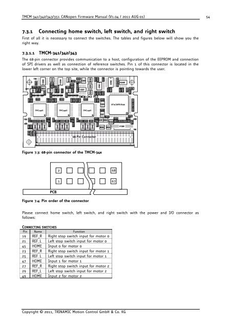
7.3.1 Connecting home switch, left switch, and right switch<br />
First of all it is necessary to connect the switches. The tables and figures below will show you the<br />
right way.<br />
7.3.1.1 <strong>TMCM</strong>-341/342/343<br />
The 68-pin connector provides communication to a host, configuration of the EEPROM and connection<br />
of SPI drivers as well as connection of reference switches. Pin 1 of this connector is located in the<br />
lower left corner on the top site, while the connector is pointing towards the user.<br />
Figure 7.3: 68-pin connector of the <strong>TMCM</strong>-34x<br />
PCB<br />
2 68<br />
Figure 7.4: Pin order of the connector<br />
1<br />
Please connect home switch, left switch, and right switch with the power and I/O connector as<br />
follows:<br />
CONNECTING SWITCHES<br />
Pin Name Function<br />
19 REF_R Right stop switch input for motor 0<br />
21 REF_L Left stop switch input for motor 0<br />
45 HOME Input 0 for motor 0<br />
23 REF_R Right stop switch input for motor 1<br />
25 REF_L Left stop switch input for motor 1<br />
47 HOME Input 1 for motor 1<br />
27 REF_R Right stop switch input for motor 2<br />
29 REF_L Left stop switch input for motor 2<br />
49 HOME Input 2 for motor 2<br />
Copyright © 2011, TRINAMIC Motion Control GmbH & Co. KG<br />
67