TMCM-351 CANopen Firmware Manual - Trinamic
TMCM-351 CANopen Firmware Manual - Trinamic
TMCM-351 CANopen Firmware Manual - Trinamic

Create successful ePaper yourself
Turn your PDF publications into a flip-book with our unique Google optimized e-Paper software.
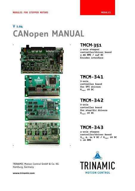
MODULES FOR STEPPER MOTORS MODULES<br />
V 1.04<br />
<strong>CANopen</strong> MANUAL<br />
+ + <strong>TMCM</strong>-<strong>351</strong><br />
3-axis stepper<br />
controller/driver board<br />
2.8A RMS / 24V DC<br />
Encoder interface<br />
+ +<br />
TRINAMIC Motion Control GmbH & Co. KG<br />
Hamburg, Germany<br />
www.trinamic.com<br />
<strong>TMCM</strong>-341<br />
3-axis<br />
controller board<br />
for SPI drivers<br />
V logic 5V DC<br />
<strong>TMCM</strong>-342<br />
3-axis<br />
controller board<br />
for step/dir drivers<br />
V logic 5V DC<br />
<strong>TMCM</strong>-343<br />
3-axis stepper<br />
controller/driver board<br />
V nom 8… 34 V DC / V logic 5V DC<br />
1.1A RMS
<strong>TMCM</strong>-341/342/343/<strong>351</strong> <strong>CANopen</strong> <strong>Firmware</strong> <strong>Manual</strong> (V1.04 / 2011-AUG-01) 2<br />
Table of contents<br />
1 Life support policy ....................................................................................................................................................... 6<br />
2 About this document .................................................................................................................................................. 7<br />
3 Features ........................................................................................................................................................................... 8<br />
3.1 Features of <strong>TMCM</strong>-341 ........................................................................................................................................ 8<br />
3.2 Features of the <strong>TMCM</strong>-342 ................................................................................................................................. 9<br />
3.3 Features of the <strong>TMCM</strong>-343 ............................................................................................................................... 10<br />
3.4 Features of the <strong>TMCM</strong>-<strong>351</strong> ............................................................................................................................... 11<br />
3.5 General features of this <strong>CANopen</strong> implementation ................................................................................ 12<br />
4 Order codes .................................................................................................................................................................. 13<br />
5 Communication ........................................................................................................................................................... 14<br />
5.1 Reference model ................................................................................................................................................ 14<br />
5.2 NMT state machine ............................................................................................................................................ 15<br />
5.3 Device model ...................................................................................................................................................... 17<br />
5.4 Object Dictionary ............................................................................................................................................... 18<br />
6 Communication objects ............................................................................................................................................ 19<br />
6.1 Detailed object specifications ........................................................................................................................ 19<br />
6.1.1 Object 1000 h: Device type.......................................................................................................................... 19<br />
6.1.2 Object 1001 h: Error register ....................................................................................................................... 19<br />
6.1.3 Object 1005 h: COB-ID SYNC Message ..................................................................................................... 20<br />
6.1.4 Object 1008 h: Manufacturer device name ............................................................................................. 20<br />
6.1.5 Object 1009 h: Manufacturer hardware version .................................................................................... 20<br />
6.1.6 Object 1010 h: Store parameters ............................................................................................................... 21<br />
6.1.7 Object 1011 h: Restore default parameters ............................................................................................ 22<br />
6.1.8 Object 100A h: Manufacturer software version ..................................................................................... 23<br />
6.1.9 Object 1014 h: COB-ID emergency object ............................................................................................... 23<br />
6.1.10 Object 1015 h: Inhibit time EMCY ............................................................................................................. 24<br />
6.1.11 Object 1016 h: Consumer heartbeat time ............................................................................................... 24<br />
6.1.12 Object 1017 h: Producer heartbeat time ................................................................................................. 24<br />
6.1.13 Object 1018 h: Identity object.................................................................................................................... 25<br />
6.1.14 Object 1023 h: OS command ...................................................................................................................... 25<br />
6.1.15 Object 1029 h: Error behavior .................................................................................................................... 26<br />
6.1.16 Objects 1400 h-1405 h: Receive PDO communication parameter ....................................................... 26<br />
6.1.17 Objects 1440 h-1445 h: Receive PDO communication parameter ....................................................... 27<br />
6.1.18 Objects 1480 h-1485 h: Receive PDO communication parameter ....................................................... 27<br />
6.1.19 Objects 1600 h-1605 h: Receive PDO mapping ........................................................................................ 28<br />
6.1.20 Objects 1640 h-1645 h: Receive PDO mapping ........................................................................................ 29<br />
6.1.21 Objects 1680 h-1685 h: Receive PDO mapping ........................................................................................ 30<br />
6.1.22 Objects 1800 h-1805 h: Transmit PDO communication parameter .................................................... 31<br />
6.1.23 Objects 1840 h-1845 h: Transmit PDO communication parameter .................................................... 32<br />
6.1.24 Objects 1880 h-1885 h: Transmit PDO communication parameter .................................................... 33<br />
6.1.25 Objects 1A00 h-1A05 h: Transmit PDO mapping parameter ................................................................ 34<br />
6.1.26 Objects 1A40 h-1A45 h: Transmit PDO mapping parameter ................................................................ 35<br />
6.1.27 Objects 1A80 h-1A85 h: Transmit PDO mapping parameter ................................................................ 36<br />
7 Device profile objects (CiA402) and modes of operation .............................................................................. 37<br />
7.1 Detailed object specifications ........................................................................................................................ 37<br />
7.1.1 Object 605A h, 685A h, and 705A h: Quick stop option code ............................................................... 37<br />
7.1.2 Object 605B h, 685B h, and 705B h: Shutdown option code ................................................................ 38<br />
7.1.3 Object 605C h, 685C h, and 705C h: Disable operation option code ................................................... 38<br />
7.1.4 Object 605D h, 685D h, and 705D h: Halt option code ............................................................................ 39<br />
7.1.5 Object 605E h, 685E h, and 705E h: Fault reaction option code ........................................................... 39<br />
7.1.6 Object 6060 h, 6860 h, and 7060 h: Modes of operation ........................................................................ 40<br />
7.1.7 Object 6061 h, 6861 h, and 7061 h: Modes of operation display ......................................................... 40<br />
7.1.8 Object 606A h, 686A h, and 706A h: Sensor selection code .................................................................. 41<br />
7.1.9 Object 60C5 h, 68C5 h, and 70C5 h: Max acceleration ............................................................................. 41<br />
7.1.10 Object 60C6 h, 68C6 h, and 70C6 h: Max deceleration ............................................................................. 41<br />
Copyright © 2011, TRINAMIC Motion Control GmbH & Co. KG
<strong>TMCM</strong>-341/342/343/<strong>351</strong> <strong>CANopen</strong> <strong>Firmware</strong> <strong>Manual</strong> (V1.04 / 2011-AUG-01) 3<br />
7.1.11 Object 60FD h, 68FD h, and 70FD h: Digital inputs .................................................................................. 42<br />
7.1.12 Object 6502 h, 6D02 h, and 7502 h: Supported drive modes ................................................................ 42<br />
7.2 Profile position mode ...................................................................................................................................... 43<br />
7.2.1 Detailed object specifications .................................................................................................................. 43<br />
7.2.1.1 Object 6040 h, 6840 h, and 7040 h: Controlword............................................................................ 44<br />
7.2.1.2 Object 6041 h, 6841 h, and 7041 h: Statusword .............................................................................. 45<br />
7.2.1.3 Object 6062 h, 6862 h, and 7062 h: Position demand value ....................................................... 46<br />
7.2.1.4 Object 6063 h, 6863 h, and 7063 h: Position actual internal value ........................................... 46<br />
7.2.1.5 Object 6064 h, 6864 h, and 7064 h: Position actual value ........................................................... 46<br />
7.2.1.6 Object 6065 h, 6865 h, and 7065 h: Following error window .................................................... 47<br />
7.2.1.7 Object 6067 h, 6867 h, and 7067 h: Position window ................................................................... 47<br />
7.2.1.8 Object 6068 h, 6868 h, and 7068 h: Position window time ......................................................... 48<br />
7.2.1.9 Object 607A h, 687A h, and 707A h: Target position ..................................................................... 48<br />
7.2.1.10 Object 607D h, 687D h, and 707D h: Software position limit ..................................................... 49<br />
7.2.1.11 Object 607F h, 687F h, and 707F h: Maximum profile velocity ................................................... 49<br />
7.2.1.12 Object 6081 h, 6881 h, and 7081 h: Profile velocity ....................................................................... 50<br />
7.2.1.13 Object 6083 h, 6883 h, and 7083 h: Profile acceleration ............................................................... 50<br />
7.2.1.14 Object 6084 h, 6884 h, and 7084 h: Profile deceleration .............................................................. 50<br />
7.2.1.15 Object 6085 h, 6885 h, and 7085 h: Quick stop deceleration ...................................................... 51<br />
7.2.1.16 Object 6086 h, 6886 h, and 7086 h: Motion profile type .............................................................. 51<br />
7.2.1.17 Object 608F h, 688F h, and 708F h: Position encoder resolution .............................................. 52<br />
7.2.2 How to move a motor in pp mode ....................................................................................................... 52<br />
7.3 Homing mode ..................................................................................................................................................... 53<br />
7.3.1 Connecting home switch, left switch, and right switch .................................................................. 54<br />
7.3.1.1 <strong>TMCM</strong>-341/342/343 ............................................................................................................................. 54<br />
7.3.1.2 <strong>TMCM</strong>-<strong>351</strong> ............................................................................................................................................. 55<br />
7.3.2 Connecting a brake ..................................................................................................................................... 56<br />
7.3.2.1 <strong>TMCM</strong>-341/342/343 ............................................................................................................................. 56<br />
7.3.2.2 <strong>TMCM</strong>-<strong>351</strong> ............................................................................................................................................. 56<br />
7.3.3 Homing methods: Homing on negative home switch and index pulse..................................... 57<br />
7.3.4 Detailed object definitions ....................................................................................................................... 58<br />
7.3.4.1 Object 6040 h, 6840 h, and 7040 h: Controlword............................................................................ 58<br />
7.3.5 Object 6041 h, 6841 h, and 7041 h: Statusword ........................................................................................ 59<br />
7.3.5.1 Object 607C h, 687C h, and 707C h: Home offset ........................................................................... 60<br />
7.3.5.2 Object 6098 h, 6898 h, and 7098 h: Homing method .................................................................... 60<br />
7.3.5.3 Object 6099 h, 6899 h, and 7099 h: Homing speeds ...................................................................... 61<br />
7.3.5.4 Object 609A h, 689A h, and 709A h: Homing acceleration ........................................................... 61<br />
7.3.6 How to start a homing in hm mode..................................................................................................... 61<br />
7.4 Velocity mode ..................................................................................................................................................... 62<br />
7.4.1 Detailed object definitions ....................................................................................................................... 62<br />
7.4.1.1 Object 6040 h, 6840 h, and 7040 h: Controlword............................................................................ 62<br />
7.4.1.2 Object 6041 h, 6841 h, and 7041 h: Statusword .............................................................................. 63<br />
7.4.1.3 Object 6042 h, 6842 h, and 7042 h: vl target velocity ................................................................... 63<br />
7.4.1.4 Object 6043 h, 6843 h, and 7043 h: vl velocity demand ............................................................... 64<br />
7.4.1.5 Object 6044 h, 6844 h, and 7044 h: vl velocity actual value........................................................ 64<br />
7.4.1.6 Object 6046 h, 6846 h, and 7046 h: vl velocity min max amount.............................................. 64<br />
7.4.1.7 Object 6048 h, 6848 h, and 7048 h: vl velocity acceleration ........................................................ 65<br />
7.4.1.8 Object 6049 h, 6849 h, and 7049 h: vl velocity deceleration ....................................................... 65<br />
7.4.1.9 Object 6062 h, 6862 h, and 7062 h: Position demand value ....................................................... 66<br />
7.4.1.10 Object 6063 h, 6863 h, and 7063 h: Position actual internal value ........................................... 66<br />
7.4.1.11 Object 6064 h, 6864 h, and 7064 h: Position actual value ........................................................... 66<br />
7.4.1.12 Object 6065 h, 6865 h, and 7065 h: Following error window .................................................... 67<br />
7.4.1.13 Object 607D h, 687D h, and 707D h: Software position limit ..................................................... 67<br />
7.4.1.14 Object 6083 h, 6883 h, and 7083 h: Profile acceleration ............................................................... 68<br />
7.4.1.15 Object 6084 h, 6884 h, and 7084 h: Profile deceleration .............................................................. 68<br />
7.4.1.16 Object 6085 h, 6885 h, and 7085 h: Quick stop deceleration ...................................................... 69<br />
7.4.2 How to move a motor in vl mode ........................................................................................................ 69<br />
Copyright © 2011, TRINAMIC Motion Control GmbH & Co. KG
<strong>TMCM</strong>-341/342/343/<strong>351</strong> <strong>CANopen</strong> <strong>Firmware</strong> <strong>Manual</strong> (V1.04 / 2011-AUG-01) 4<br />
8 Manufacturer specific area ....................................................................................................................................... 70<br />
8.1 Detailed object specifications ........................................................................................................................ 70<br />
8.1.1 Object 2000 h, 2200 h, and 2400 h: Microstep resolution ...................................................................... 70<br />
8.1.2 Object 2001 h, 2201 h, and 2401 h: Fullstep resolution .......................................................................... 70<br />
8.1.3 Object 2002 h, 2202 h, and 2402 h: Brake delay times ........................................................................... 71<br />
8.1.4 Object 2003 h, 2203 h, and 2403 h: Maximum current ............................................................................ 71<br />
8.1.5 Object 2004 h, 2204 h, and 2404 h: Standby current ............................................................................... 72<br />
8.1.6 Object 2005 h, 2205 h, and 2405 h: Limit switches .................................................................................. 72<br />
8.1.7 Object 2006 h, 2206 h, and 2406 h: Mixed decay threshold................................................................... 73<br />
8.1.8 Object 2007 h, 2207 h, and 2407 h: Stall detection threshold .............................................................. 73<br />
8.1.9 Object 2009 h, 2209 h, and 2409 h: Fullstep threshold ........................................................................... 73<br />
8.1.10 Object 200A h, 220A h, and 240A h: Enable drive delay time ............................................................... 74<br />
8.1.11 Object 200B h, 220B h, and 240B h: Encoder parameters....................................................................... 74<br />
8.1.12 Object 200C h, 220C h, and 240C h: Brake current feed .......................................................................... 75<br />
8.1.13 Object 2085 h, 2285 h, and 2485 h: Ramp divisor .................................................................................... 75<br />
8.1.14 Object 2086 h, 2286 h, and 2486 h: Pulse divisor ..................................................................................... 76<br />
8.1.15 Object 2087 h, 2287 h, and 2487 h: Maximum velocity ........................................................................... 76<br />
8.1.16 Object 2088 h, 2288 h, and 2488 h: Maximum acceleration ................................................................... 77<br />
8.1.17 Object 208C h, 228C h, and 248C h: Velocity dimension index ............................................................. 77<br />
8.1.18 Object 208E h, 228E h, and 248E h: Acceleration dimension index ..................................................... 77<br />
8.1.19 Object 2100 h, 2300 h, and 2500 h: Home offset display ....................................................................... 78<br />
8.1.20 Object 2101 h, 2301 h, and 2501 h: Actual stallGuard load value .................................................... 78<br />
8.1.21 Object 2102 h, 2302 h, and 2502 h: Driver error flags ............................................................................. 78<br />
8.1.22 Object 2103 h, 2303 h, and 2503 h: Pulse divisor display ...................................................................... 79<br />
8.1.23 Object 2104 h, 2304 h, and 2504 h: Maximum velocity display ............................................................ 79<br />
8.1.24 Object 2105 h, 2305 h, and 2505 h: Ramp divisor display ..................................................................... 79<br />
8.1.25 Object 2106 h, 2306 h, and 2506 h: Maximum acceleration display .................................................... 80<br />
8.1.26 Object 2107 h, 2307 h, and 2507 h: Microstep resolution display ....................................................... 80<br />
8.1.27 Object 2700 h: TMCL direct communication ....................................................................................... 80<br />
8.1.28 Object 2701 h: Manufacturer specific mode ........................................................................................... 81<br />
8.1.29 Object 2702 h: Digital inputs ...................................................................................................................... 81<br />
8.1.30 Object 2703 h: Digital outputs ................................................................................................................... 81<br />
8.1.31 Object 2704 h: CAN bit rate ........................................................................................................................ 82<br />
8.1.32 Object 2705 h: Node ID ................................................................................................................................ 82<br />
8.1.33 Object 2706 h: Store ...................................................................................................................................... 82<br />
8.1.34 Object 2707 h: CAN bit rate load ............................................................................................................... 83<br />
8.1.35 Object 2708 h: Node ID load ...................................................................................................................... 83<br />
8.1.36 Object 2709 h: Encoder interface ............................................................................................................... 83<br />
8.1.37 Object 270A h: Encoder interface display ............................................................................................... 83<br />
8.1.38 Object 270E h: Analog inputs ..................................................................................................................... 83<br />
9 Emergency messages ................................................................................................................................................ 85<br />
10 Revision history .......................................................................................................................................................... 87<br />
10.1 <strong>Firmware</strong> revision .............................................................................................................................................. 87<br />
10.2 Document revision ............................................................................................................................................ 87<br />
11 References..................................................................................................................................................................... 88<br />
Copyright © 2011, TRINAMIC Motion Control GmbH & Co. KG
<strong>TMCM</strong>-341/342/343/<strong>351</strong> <strong>CANopen</strong> <strong>Firmware</strong> <strong>Manual</strong> (V1.04 / 2011-AUG-01) 5<br />
Table of figures<br />
Figure 5.1: Overview <strong>CANopen</strong> NMT state machine .................................................................................................. 15<br />
Figure 5.2: Communication architecture ....................................................................................................................... 16<br />
Figure 5.3: Device model .................................................................................................................................................. 17<br />
Figure 6.1: Restore procedure.......................................................................................................................................... 22<br />
Figure 7.1: Finite state machine ..................................................................................................................................... 43<br />
Figure 7.2: Homing mode function ................................................................................................................................ 53<br />
Figure 7.3: 68-pin connector of the <strong>TMCM</strong>-34x ........................................................................................................... 54<br />
Figure 7.4: Pin order of the connector ......................................................................................................................... 54<br />
Figure 7.5: Connectors of <strong>TMCM</strong>-<strong>351</strong>.............................................................................................................................. 55<br />
Figure 7.6: Homing on negative home switch and index pulse ........................................................................... 57<br />
Figure 7.7: Home offset definition ................................................................................................................................. 60<br />
Figure 7.8: Transfer characteristic of the velocity acceleration ............................................................................. 65<br />
Figure 8.1: Brake output timing ...................................................................................................................................... 71<br />
Copyright © 2011, TRINAMIC Motion Control GmbH & Co. KG
<strong>TMCM</strong>-341/342/343/<strong>351</strong> <strong>CANopen</strong> <strong>Firmware</strong> <strong>Manual</strong> (V1.04 / 2011-AUG-01) 6<br />
1 Life support policy<br />
TRINAMIC Motion Control GmbH & Co. KG does not<br />
authorize or warrant any of its products for use in life<br />
support systems, without the specific written consent<br />
of TRINAMIC Motion Control GmbH & Co. KG.<br />
Life support systems are equipment intended to<br />
support or sustain life, and whose failure to perform,<br />
when properly used in accordance with instructions<br />
provided, can be reasonably expected to result in<br />
personal injury or death.<br />
© TRINAMIC Motion Control GmbH & Co. KG 2011<br />
Information given in this data sheet is believed to be<br />
accurate and reliable. However neither responsibility<br />
is assumed for the consequences of its use nor for<br />
any infringement of patents or other rights of third<br />
parties, which may result from its use.<br />
Specifications are subject to change without notice.<br />
Copyright © 2011, TRINAMIC Motion Control GmbH & Co. KG
<strong>TMCM</strong>-341/342/343/<strong>351</strong> <strong>CANopen</strong> <strong>Firmware</strong> <strong>Manual</strong> (V1.04 / 2011-AUG-01) 7<br />
2 About this document<br />
This document specifies objects and modes of operation of the TRINAMIC modules <strong>TMCM</strong>-341, <strong>TMCM</strong>-<br />
342, <strong>TMCM</strong>-343, and <strong>TMCM</strong>-<strong>351</strong> with <strong>CANopen</strong> firmware. As these products are stepper motor controller<br />
and driver modules the use of the CiA DSP402 protocol (described in the CiA <strong>CANopen</strong> drives and<br />
motion control device profile, Part 2) is fundamental. The <strong>CANopen</strong> firmware is designed to fulfill the<br />
DS301 version 4.02 and DS402 version 3.o standards. The CiA conformance has also been tested. This<br />
<strong>CANopen</strong> firmware has been developed to turn the ARM-based TRINAMIC motion control modules into<br />
<strong>CANopen</strong> compatible ones. There are versions each module.<br />
As with most TRINAMIC modules the software running on the microprocessor of the <strong>TMCM</strong>-341,<br />
<strong>TMCM</strong>-342, <strong>TMCM</strong>-343, and <strong>TMCM</strong>-<strong>351</strong> consists of two parts, a boot loader and the <strong>CANopen</strong> firmware<br />
itself. Whereas the boot loader is installed during production and testing at TRINAMIC and remains –<br />
normally – untouched throughout the whole lifetime, the <strong>CANopen</strong> firmware can be updated by the<br />
user. New versions can be downloaded free of charge from the TRINAMIC website<br />
(http://www.trinamic.com). The <strong>CANopen</strong> firmware can be loaded into the modules easily just by<br />
using the firmware update function of the TMCL-IDE.<br />
It is also still possible to control the drive using TMCL commands via a special vendor-specific<br />
object. You can turn the drive back into a TMCL module by loading the TMCL firmware into the<br />
drive again.<br />
This manual assumes that the reader is already familiar with the basics of the <strong>CANopen</strong> protocol<br />
(especially DS301 and DS402). On the following pages you will find a short introduction or rather a<br />
short overview and afterwards the information will be more in detail.<br />
ABBREVIATIONS<br />
CAN Controller area network<br />
COB Communication object<br />
FSA Finite state automation<br />
FSM Finite state machine<br />
NMT Network management<br />
ID Identifier<br />
LSB Least significant bit<br />
MSB Most significant bit<br />
PDO Process data object<br />
PDS Power drive system<br />
RPDO Receive process data object<br />
SDO Service data object<br />
TPDO Transmit process data object<br />
EMCY Emergency object<br />
rw Read and write<br />
ro Read only<br />
hm Homing mode<br />
pp Profile position mode<br />
pv Profile velocity mode<br />
Table 2.1: Abbreviations<br />
Copyright © 2011, TRINAMIC Motion Control GmbH & Co. KG
<strong>TMCM</strong>-341/342/343/<strong>351</strong> <strong>CANopen</strong> <strong>Firmware</strong> <strong>Manual</strong> (V1.04 / 2011-AUG-01) 8<br />
3 Features<br />
The following text gives an overview of the four TRINAMIC products which are discussed in this<br />
manual.<br />
3.1 Features of <strong>TMCM</strong>-341<br />
The <strong>TMCM</strong>-341 is a triple axis stepper motor controller module for external power drivers with SPI<br />
interface (e.g. TRINAMIC <strong>TMCM</strong>-035). With its very small size it is dedicated to embedded applications,<br />
where a compact solution is required.<br />
The <strong>TMCM</strong>-341 can be controlled via the serial UART interface (e.g. using a RS232 or RS485 level<br />
shifter) or via CAN. The firmware of the module can be updated via the serial interface as well as via<br />
the CAN interface.<br />
Applications<br />
Controller board for control of up to 3 two-phase bipolar motors using SPI drivers (e.g. <strong>TMCM</strong>-035<br />
or TMC249)<br />
Versatile possibilities of applications in standalone (only with TMCL - refer to the <strong>TMCM</strong>-341<br />
TMCL <strong>Firmware</strong> <strong>Manual</strong>) or host controlled mode (<strong>CANopen</strong> and TMCL)<br />
Electrical Data<br />
5V DC logic power supply<br />
Interface<br />
RS232, RS485 (max. 115200bps) or CAN 2.0b (max. 1MBit/s) host interface<br />
Inputs for reference and stop switches, general purpose analog and digital I/Os<br />
Highlights<br />
Up to 64 times microstepping<br />
Automatic ramp generation in hardware<br />
On the fly alteration of motion parameters (e.g. position, velocity, acceleration)<br />
High dynamics: full step frequencies up to 90kHz, microstep frequency up to 460kHz<br />
Supports stallGuard option for sensorless motor stall detection<br />
Can be adapted to any SPI driver type<br />
Software<br />
<strong>CANopen</strong> firmware (DS301 + DSP402 with homing mode, profile position mode, and velocity<br />
mode)<br />
Alternative: TMCL remote (direct mode) or stand-alone operation (memory for 2048 TMCL<br />
commands). TMCL is fully supported by TMCL-IDE (PC based integrated development<br />
environment).<br />
Other<br />
68 pin connector carries all signals (2*34 pins, 2mm pitch)<br />
RoHS compliant<br />
Size: 80 x 50 mm²<br />
Copyright © 2011, TRINAMIC Motion Control GmbH & Co. KG
<strong>TMCM</strong>-341/342/343/<strong>351</strong> <strong>CANopen</strong> <strong>Firmware</strong> <strong>Manual</strong> (V1.04 / 2011-AUG-01) 9<br />
3.2 Features of the <strong>TMCM</strong>-342<br />
The <strong>TMCM</strong>-342 is a triple axis stepper motor controller module for external power drivers with<br />
step/direction interface. With its very small size it is dedicated to embedded applications, where<br />
centralized or decentralized high power drivers are desired. The board can be connected to a<br />
baseboard or customized electronics with a pin connector.<br />
The <strong>TMCM</strong>-342 can be controlled via the serial UART interface (e.g. using a RS232 or RS485 level<br />
shifter) or via CAN. Communication traffic is kept very low since all time critical operations, e.g. ramp<br />
calculation, are performed on board. The firmware of the module can be updated via the serial<br />
interface as well as via the CAN interface.<br />
Applications<br />
Controller board for control of up to 3 step/direction drivers e.g. <strong>TMCM</strong>-035, <strong>TMCM</strong>-023 (triple<br />
driver), IDX or PD-013-42 mechatronic module or <strong>TMCM</strong>-078 step/direction driver<br />
Versatile possibilities of applications in stand alone or host controlled mode<br />
Electrical data<br />
5V DC logic power supply<br />
TTL/CMOS step/direction outputs<br />
Interface<br />
RS232, RS485 (max. 115200bps) or CAN 2.0b (max. 1MBit/s) host interface<br />
Inputs for reference and stop switches, general purpose analog and digital I/Os<br />
Step/direction outputs for three stepper motor drivers<br />
Highlights<br />
Three TMC428-I motion controllers for high step frequency<br />
Automatic ramp generation in hardware<br />
On the fly alteration of motion parameters (e.g. position, velocity, acceleration)<br />
High dynamics: step frequencies up to 300kHz<br />
1.8µs step pulse length and step to direction delay<br />
Software<br />
<strong>CANopen</strong> firmware (DS301 + DSP402 with homing mode, profile position mode, and velocity<br />
mode)<br />
Alternative: TMCL remote (direct mode) or stand-alone operation (memory for 2048 TMCL<br />
commands). TMCL is fully supported by TMCL-IDE (PC based integrated development<br />
environment).<br />
Other<br />
68 pin connector carries all signals (2*34 pins, 2mm pitch)<br />
RoHS compliant<br />
Size: 80 x 50 mm²<br />
Copyright © 2011, TRINAMIC Motion Control GmbH & Co. KG
<strong>TMCM</strong>-341/342/343/<strong>351</strong> <strong>CANopen</strong> <strong>Firmware</strong> <strong>Manual</strong> (V1.04 / 2011-AUG-01) 10<br />
3.3 Features of the <strong>TMCM</strong>-343<br />
The <strong>TMCM</strong>-343 is a compact and versatile triple axis 2-phase stepper motor controller and driver<br />
module. It provides a complete motion control solution at a very small size for embedded<br />
applications. Using the integrated additional I/Os it even can do complete system control applications.<br />
The board can be connected to a baseboard or customized electronics with a pin connector.<br />
Host communication is possible via the serial UART interface (e.g. using a RS232 or RS485 level shifter)<br />
or via CAN. All time critical operations, e.g. ramp calculation are performed onboard. The firmware of<br />
the module can be updated via the serial interface.<br />
With the optional stallGuard feature it is possible to detect overload and stall of the motor.<br />
Applications<br />
Controller/driver board for control of up to three axes<br />
Versatile possibilities of applications in stand alone or pc controlled mode<br />
Electrical data<br />
5V DC logic power supply<br />
Nominal motor supply voltage 8V… 34V<br />
Motor type<br />
Coil current from 300mA to 1.1A RMS (1.5A peak)<br />
8V… 34V nominal supply voltage<br />
Highlights<br />
Automatic ramp generation in hardware<br />
stallGuard option for sensorless motor stall detection<br />
Full step frequencies up to 20kHz<br />
On the fly alteration of motion parameters (e.g. position, velocity, acceleration)<br />
Local reference move using sensorless stallGuard feature or reference switch<br />
Coil current adjustable by software<br />
TMC428 motion controller for up to 64 times microstepping<br />
TMC246 power driver: No heat sink required<br />
Many adjustment possibilities make this module the solution for a great field of demands<br />
Software<br />
<strong>CANopen</strong> firmware (DS301 + DSP402 with homing mode, profile position mode, and velocity<br />
mode)<br />
Alternative: TMCL remote (direct mode) or stand-alone operation (memory for 2048 TMCL<br />
commands). TMCL is fully supported by TMCL-IDE (PC based integrated development<br />
environment).<br />
Other<br />
68 pin connector carries all signals (2*34 pins, 2mm pitch)<br />
RoHS compliant<br />
Size: 80 x 50 mm²<br />
Copyright © 2011, TRINAMIC Motion Control GmbH & Co. KG
<strong>TMCM</strong>-341/342/343/<strong>351</strong> <strong>CANopen</strong> <strong>Firmware</strong> <strong>Manual</strong> (V1.04 / 2011-AUG-01) 11<br />
3.4 Features of the <strong>TMCM</strong>-<strong>351</strong><br />
The <strong>TMCM</strong>-<strong>351</strong> is a powerful three axes bipolar stepper motor controller/driver board with optional<br />
encoder interface for all three axes and a large number of general purpose digital and analogue<br />
input/outputs. Several different serial communication interfaces are available.<br />
Electrical data<br />
Supply voltage: +24V DC nominal (28.5V DC max.)<br />
Motor current: up to 2.8A RMS per axis (programmable)<br />
Stepper motor data<br />
two phase bipolar stepper motors with up to 2.8A RMS coil current<br />
optional incremental encoder interface (a/b/n), accepts differential or single ended input signals<br />
Interfaces<br />
2 reference switch inputs per motor axis (6 altogether, internal pull-up resistors, +24V compatible)<br />
8 general purpose inputs (+24V compatible)<br />
8 general purpose outputs incl. two power outputs (all open-collector)<br />
1 shutdown input (enable/disable driver stage in hardware)<br />
4 dedicated analogue inputs (programmable 3.3V/10V input range)<br />
SPI connector with three chip select signals for I/O extension<br />
RS232, RS485, CAN and USB serial communication interfaces<br />
Features<br />
High-efficient operation, low power-dissipation (TMC249 stepper driver with external MOSFETs)<br />
Dynamic current control<br />
Integrated Protection<br />
On the fly alteration of motor parameters (e.g. position, velocity, acceleration)<br />
Motion profile calculation in real-time (TMC428 motion controller)<br />
Each axis individually and independently programmable<br />
Supports up to 64 microsteps per fullstep<br />
Integrated stallGuard TM for motor stall detection (e.g. elimination of end switches)<br />
Closed-loop operation with TMCL possible (when using the optional incremental encoder<br />
interface)<br />
Software<br />
<strong>CANopen</strong> firmware (DS301 + DSP402 with homing mode, profile position mode, and velocity<br />
mode)<br />
Alternative: TMCL remote (direct mode) or stand-alone operation (memory for 2048 TMCL<br />
commands). TMCL is fully supported by TMCL-IDE (PC based integrated development<br />
environment).<br />
Copyright © 2011, TRINAMIC Motion Control GmbH & Co. KG
<strong>TMCM</strong>-341/342/343/<strong>351</strong> <strong>CANopen</strong> <strong>Firmware</strong> <strong>Manual</strong> (V1.04 / 2011-AUG-01) 12<br />
3.5 General features of this <strong>CANopen</strong> implementation<br />
The general features of this <strong>CANopen</strong> implementation are:<br />
Communication according to standard CiA-301 V4.1<br />
CAN bit rate: 1000kBit/s<br />
CAN ID: 11 bit<br />
Node ID: 1… 127, settable by vendor specific objects<br />
NMT services: NMT slave<br />
SDO communication:<br />
1 server<br />
expedited transfer<br />
segmented transfer<br />
no block transfer<br />
PDO communication:<br />
Producer<br />
Consumer<br />
RPDOs:<br />
Axis 0: 1, 2, 3, 4, 6<br />
Axis 1: 65, 66, 67, 68, 70<br />
Axis 2: 129, 130, 131, 132, 134<br />
Transmission modes: asynchronous<br />
Dynamic mapping with max. 3 mapping entries<br />
Default mappings: according to CiA-402 for PDO 1, 2, 3 and 6, manufacturer<br />
specific for PDO4<br />
TPDOs:<br />
Axis 0: 1, 2, 3, 4, 6<br />
Axis 1: 65, 66, 67, 68, 70<br />
Axis 2: 129, 130, 131, 132, 134<br />
Transmission modes: asynchronous, asynchronous with event timer,<br />
synchronous<br />
Dynamic mapping with max. 3 mapping entries<br />
Default mappings: according to CiA-402 for PDO 1, 2, 3 and 6, manufacturer<br />
specific for PDO<br />
SYNC: consumer (TPDO3 and TPDO6 are synchronous PDOs)<br />
Emergency: producer<br />
RTR: not supported<br />
Copyright © 2011, TRINAMIC Motion Control GmbH & Co. KG
<strong>TMCM</strong>-341/342/343/<strong>351</strong> <strong>CANopen</strong> <strong>Firmware</strong> <strong>Manual</strong> (V1.04 / 2011-AUG-01) 13<br />
4 Order codes<br />
Order code Description Dimensions<br />
<strong>TMCM</strong>-341-option 1-option 2 3-axis controller module with SPI TM 80 x 55 x 5 mm 3<br />
<strong>TMCM</strong>-342-option 1-option 2 3-axis controller module with step/dir output 80 x 55 x 8 mm 3<br />
<strong>TMCM</strong>-343-option 1-option 2 3-axis controller/driver module 1.1A 80 x 55 x 8 mm 3<br />
<strong>TMCM</strong>-<strong>351</strong>-option 3-axis controller/driver module 2.8A 100 x 60 x 29 mm 3<br />
Option 1 for <strong>TMCM</strong>-341/-342/-343<br />
-V vertical pin connector (on request)<br />
-H horizontal pin connector (standard)<br />
Option 2 for <strong>TMCM</strong>-341/-342/-343<br />
-TMCL with TMCL (standard)<br />
-<strong>CANopen</strong> with <strong>CANopen</strong><br />
Options for <strong>TMCM</strong>-<strong>351</strong><br />
without option specification no encoder interface, <strong>TMCM</strong>-<strong>351</strong> comes with TMCL<br />
-E with encoder interface<br />
-<strong>CANopen</strong> with <strong>CANopen</strong><br />
-E-<strong>CANopen</strong> with encoder interface and <strong>CANopen</strong><br />
Products related to <strong>TMCM</strong>-341: Description Dimensions<br />
BB-301 (-option) Baseboard for <strong>TMCM</strong>-341 and 3 x <strong>TMCM</strong>-035 90 x 87 x 60 mm 3<br />
BB-301S (-option) Baseboard for <strong>TMCM</strong>-341 and 3 x <strong>TMCM</strong>-035 133 x 100 x 60 mm 3<br />
<strong>TMCM</strong>-035 1-axis driver 3.5A, 50V with stallGuard TM 80 x 50 x 9 mm 3<br />
<strong>TMCM</strong>-323 3-axis encoder 80 x 53 x 8 mm 3<br />
<strong>TMCM</strong>-EVAL Evaluation baseboard 160 x 100 x 24 mm 3<br />
Products related to <strong>TMCM</strong>-342 Description Dimensions<br />
BB-302 (-option) Baseboard for <strong>TMCM</strong>-342 80 x 50 x 15 mm 3<br />
BB-323-02 Baseboard for <strong>TMCM</strong>-342 87 x 77 x 60 mm 3<br />
<strong>TMCM</strong>-023 3-axis step/direction driver module 2A, 28.5V 60 x 100 x 12 mm 3<br />
<strong>TMCM</strong>-323 3-axis encoder 80 x 53 x 8 mm 3<br />
<strong>TMCM</strong>-078 1-axis step/direction driver module 7A, 75V 145 x 96 x 33 mm 3<br />
<strong>TMCM</strong>-EVAL Evaluation baseboard 160 x 100 x 24 mm 3<br />
PDx-013-42 PANdrive with step/dir 42.2 x 42.2 x 72/83/90<br />
mm 3<br />
IDX-7505 1-axis step/direction driver module 5A, 75V 65 x 64 x 24 mm 3<br />
Products related to <strong>TMCM</strong>-343 Description Dimensions<br />
BB-303 (-option) Baseboard for <strong>TMCM</strong>-343 80 x 50 x 15 mm 3<br />
BB-323-03 Baseboard for <strong>TMCM</strong>-343 96.5 x 79 x 60 mm 3<br />
<strong>TMCM</strong>-323 3-axis encoder 80 x 53 x 8 mm 3<br />
<strong>TMCM</strong>-EVAL Evaluation baseboard 160 x 100 x 24 mm 3<br />
Motors related to <strong>TMCM</strong>-<strong>351</strong> Description Dimensions<br />
QSH-5718 57mm/NEMA23, 1.8˚ step angle 57.2 x 57.2 x 41/55/<br />
78.5 mm<br />
QSH-6018 60mm/NEMA24, 1.8˚ step angle 60.5 x 60.5 x 45/56/<br />
65/86 mm<br />
Table 4.1: Order codes<br />
Copyright © 2011, TRINAMIC Motion Control GmbH & Co. KG
<strong>TMCM</strong>-341/342/343/<strong>351</strong> <strong>CANopen</strong> <strong>Firmware</strong> <strong>Manual</strong> (V1.04 / 2011-AUG-01) 14<br />
5 Communication<br />
5.1 Reference model<br />
The application layer comprises a concept to configure and communicate real-time-data as well as the<br />
mechanisms for synchronization between devices. The functionality the application layer offers to an<br />
application is logically divided over different service data objects (SDO) in the application layer. A<br />
service object offers a specific functionality and all the related services.<br />
Applications interact by invoking services of a service object in the application layer. To realize these<br />
services this object exchanges data via the CAN Network with peer service object(s) via a protocol.<br />
The application and the application layer interact with service primitives.<br />
There are four different service primitives:<br />
Request issued by the application to the application layer to request a service<br />
Indication issued by the application layer to the application to report an internal event detected<br />
by the application layer or indicate that a service is requested<br />
Response issued by the application to the application layer to respond to a previous received<br />
indication<br />
Confirmation issued by the application layer to the application to report the result of a previously<br />
issued request<br />
A service type defines the primitives that are exchanged between the application layer and the<br />
cooperating applications for a particular service of a service object.<br />
There are the following service types:<br />
Local service involves only the local service object. The application issues a request to<br />
its local service object that executes the requested service without<br />
communicating with peer service object(s)<br />
Unconfirmed service involves one or more peer service objects. The application issues a request<br />
to its local service object. This request is transferred to the peer service<br />
object(s) that each passes it to their application as an indication. The result<br />
is not confirmed back.<br />
Confirmed service can involve only one peer service object. The application issues a request<br />
to its local service object. This request is transferred to the peer service<br />
object that passes it to the other application as an indication. The other<br />
application issues a response that is transferred to the originating service<br />
object that passes it as a confirmation to the requesting application.<br />
Provider initiated service involves only the local service object. The service object (being the service<br />
provider) detects an event not solicited by a requested service. This event<br />
is then indicated to the application.<br />
Unconfirmed and confirmed services are collectively called remote services.<br />
Copyright © 2011, TRINAMIC Motion Control GmbH & Co. KG
<strong>TMCM</strong>-341/342/343/<strong>351</strong> <strong>CANopen</strong> <strong>Firmware</strong> <strong>Manual</strong> (V1.04 / 2011-AUG-01) 15<br />
5.2 NMT state machine<br />
The finite state machine (FSM) or simply state machine is a model of behavior composed of a finite<br />
number of states, transitions between those states, and actions. It shows which way the logic runs<br />
when certain conditions are met.<br />
Starting and resetting the device is controlled via the state machine. The NMT state machine consists<br />
of the following states:<br />
Initialization<br />
ID / Boot-up<br />
Pre-operational<br />
Operational<br />
Copyright © 2011, TRINAMIC Motion Control GmbH & Co. KG<br />
Stopped<br />
Figure 5.1: Overview <strong>CANopen</strong> NMT state machine<br />
After power-on or reset the device enters the Initialization state.<br />
After the device initialization is finished, the device automatically transits to the Pre-operational state<br />
and indicates this state transition by sending the boot-up message. This way the device indicates that<br />
it is ready to work. A device that stays in Pre-operational state may start to transmit SYNC-, time<br />
stamp- or heartbeat message. In contrast to the PDO communication that has to be disabled in this<br />
state, the device can communicate via SDO.<br />
The PDO communication is only possible within the Operational state. During Operational state the<br />
device can use all supported communication objects.<br />
A device that was switched to the Stopped state only reacts on received NMT commands. In addition<br />
the device indicates the current NMT state by support the error control protocol during Stopped state.<br />
The transitions between states are made by issuing a network management (NMT) communication<br />
object to the device. The NMT protocols are used to generate state machine change commands (e.g.<br />
to start and stop the device), detect remote device boot-ups and error conditions.<br />
The Heartbeat message of a <strong>CANopen</strong> device contains the device status of the NMT state machine and<br />
is sent cyclically by the <strong>CANopen</strong> device.
<strong>TMCM</strong>-341/342/343/<strong>351</strong> <strong>CANopen</strong> <strong>Firmware</strong> <strong>Manual</strong> (V1.04 / 2011-AUG-01) 16<br />
The figure below shows the situation of the state machine in this device profile:<br />
<strong>CANopen</strong> device profile CiA DSP 402<br />
Modes of operation:<br />
[used in this manual / according<br />
to CiA DSP 402]<br />
Homing mode<br />
Profile position mode<br />
Velocity mode<br />
Device control state machine<br />
<strong>CANopen</strong> Communication Profile CiA DS301<br />
CAN<br />
Figure 5.2: Communication architecture<br />
Copyright © 2011, TRINAMIC Motion Control GmbH & Co. KG
<strong>TMCM</strong>-341/342/343/<strong>351</strong> <strong>CANopen</strong> <strong>Firmware</strong> <strong>Manual</strong> (V1.04 / 2011-AUG-01) 17<br />
5.3 Device model<br />
A device is structured like the following:<br />
Communication This function unit provides the communication objects and the appropriate<br />
functionality to transport data items via the underlying network structure.<br />
Object dictionary The object dictionary is a collection of all the data items which have an<br />
influence on the behavior of the application objects, the communication<br />
objects and the state machine used on this device<br />
Application The application comprises the functionality of the device with respect to the<br />
interaction with the process environment<br />
Communication Object<br />
dictionary<br />
Application<br />
State machine Application<br />
object<br />
Communication<br />
object<br />
Communication<br />
object<br />
Communication<br />
object<br />
Communication<br />
object<br />
Entry 1<br />
Entry 2<br />
Entry n<br />
Copyright © 2011, TRINAMIC Motion Control GmbH & Co. KG<br />
Application<br />
object<br />
Application<br />
object<br />
Application<br />
object<br />
Bus system Process<br />
Figure 5.3: Device model
<strong>TMCM</strong>-341/342/343/<strong>351</strong> <strong>CANopen</strong> <strong>Firmware</strong> <strong>Manual</strong> (V1.04 / 2011-AUG-01) 18<br />
5.4 Object Dictionary<br />
The most important part of a device profile is the Object Dictionary description. The Object Dictionary<br />
is essentially a grouping of objects accessible via the network in an ordered pre-defined fashion. Each<br />
object within the dictionary is addressed using a 16-bit index.<br />
The overall layout of the standard Object Dictionary is shown below:<br />
Index (hex) Object<br />
0000 Not used<br />
0001 - 001F Static data types<br />
0020 - 003F Complex data types<br />
0040 - 005F Manufacturer specific complex data types<br />
0060 - 007F Device profile specific static data types<br />
0080 - 009F Device profile specific complex data types<br />
00A0 - 0FFF Reserved for further use<br />
1000 - 1FFF Communication profile area* 1<br />
2000 - 5FFF Manufacturer specific profile area* 2<br />
6000 - 9FFF Standardized device profile area* 3<br />
A000 - BFFF Standardized interface profile area<br />
C000 - FFFF Reserved for further use<br />
Table 5.1: Object Dictionary<br />
* 1 The communication profile area at indices 1000 h through 1FFF h contains the communication<br />
specific parameters for the CAN network. These entries are common to all devices.<br />
* 2 The manufacturer segment at indices 2000 h through 5FFF h contains manufacturer specific objects.<br />
These objects control the special features of the TRINAMIC motion control devices <strong>TMCM</strong>-<strong>351</strong> and<br />
<strong>TMCM</strong>341/342/343.<br />
* 3 The standardized device profile area at indices 6000 h through 9FFF h contains all data objects<br />
common to a class of devices that can be read or written via the network. The device profiles<br />
use entries from 6000 h to 9FFF h to describe the device parameters and the device functionality.<br />
Copyright © 2011, TRINAMIC Motion Control GmbH & Co. KG
<strong>TMCM</strong>-341/342/343/<strong>351</strong> <strong>CANopen</strong> <strong>Firmware</strong> <strong>Manual</strong> (V1.04 / 2011-AUG-01) 19<br />
6 Communication objects<br />
6.1 Detailed object specifications<br />
6.1.1 Object 1000 h: Device type<br />
This object contains information about the device type. The object 1000 h describes the type of device<br />
and its functionality. It is composed of a 16-bit field which describes the device profile that is used<br />
and a second 16-bit field which gives additional information about optional functionality of the<br />
device.<br />
OBJECT DESCRIPTION<br />
Index Name Object Code Data Type<br />
1000 h Device type Variable UNSIGNED32<br />
ENTRY DESCRIPTION<br />
Sub-Index Access PDO Mapping Value Range Default Value<br />
00 h r0 no UNSIGNED32 40192 h<br />
6.1.2 Object 1001 h: Error register<br />
This object is an error register. The module can map internal errors and object 1001 h is part of an<br />
emergency object.<br />
OBJECT DESCRIPTION<br />
Index Name Object Code Data Type<br />
1001 h Error register Variable UNSIGNED8<br />
ENTRY DESCRIPTION<br />
Sub-Index Access PDO Mapping Value Range Default Value<br />
00 h r0 yes UNSIGNED8 no<br />
STRUCTURE OF THE ERROR REGISTER<br />
Bit M/O Description<br />
0 M Generic error<br />
1 O Current<br />
2 O Voltage<br />
3 O Temperature<br />
4 O Communication error<br />
5 O Device profile specific<br />
6 O Reserved (always 0)<br />
7 O Manufacturer specific<br />
If a bit is set to 1, the specific error has occurred.<br />
Copyright © 2011, TRINAMIC Motion Control GmbH & Co. KG
<strong>TMCM</strong>-341/342/343/<strong>351</strong> <strong>CANopen</strong> <strong>Firmware</strong> <strong>Manual</strong> (V1.04 / 2011-AUG-01) 20<br />
6.1.3 Object 1005 h: COB-ID SYNC Message<br />
This object defines the COB-ID of the synchronization Object (SYNC). Further, it defines whether the<br />
module generates the SYNC.<br />
OBJECT DESCRIPTION<br />
Index Name Object Code Data Type<br />
1005 h COB-ID SYNC Message Variable UNSIGNED32<br />
ENTRY DESCRIPTION<br />
Sub-Index Access PDO Mapping Value Range Default Value<br />
00 h rw no UNSIGNED32 80 h<br />
6.1.4 Object 1008 h: Manufacturer device name<br />
This object contains the manufacturer device name.<br />
OBJECT DESCRIPTION<br />
Index Name Object Code Data Type<br />
1008 h Manufacturer device name Variable Visible string<br />
ENTRY DESCRIPTION<br />
Sub-Index Access PDO Mapping Value Range Default Value<br />
00h Const. no no<br />
<strong>TMCM</strong>-341, <strong>TMCM</strong>-342,<br />
<strong>TMCM</strong>-343 or <strong>TMCM</strong>-<strong>351</strong><br />
6.1.5 Object 1009 h: Manufacturer hardware version<br />
This object contains the hardware version description.<br />
OBJECT DESCRIPTION<br />
Index Name Object Code Data Type<br />
1009 h Manufacturer hardware version Variable Visible string<br />
ENTRY DESCRIPTION<br />
Sub-Index Access PDO Mapping Value Range Default Value<br />
00 h Const. no no Depends on device, e.g. 1.0<br />
Copyright © 2011, TRINAMIC Motion Control GmbH & Co. KG
<strong>TMCM</strong>-341/342/343/<strong>351</strong> <strong>CANopen</strong> <strong>Firmware</strong> <strong>Manual</strong> (V1.04 / 2011-AUG-01) 21<br />
6.1.6 Object 1010 h: Store parameters<br />
This object supports the saving of parameters in non volatile memory. By read access the device<br />
provides information about its saving capabilities.<br />
This command can only be carried out if the module is in ready to switch on mode.<br />
Several parameter groups are distinguished:<br />
˗ Sub-index 0 contains the largest sub-index that is supported.<br />
˗ Sub-index 1 refers to all parameters that can be stored on the device.<br />
˗ Sub-index 3 refers to application related parameters (index 6000 h - 9FFF h TRINAMICs specific<br />
application parameters).<br />
˗ Sub-index 4 stores parameters for the motor axis 0.<br />
˗ Sub-index 5 stores parameters for the motor axis 1.<br />
˗ Sub-index 6 stores parameters for the motor axis 2.<br />
In order to avoid storage of parameters by mistake, storage is only executed when the specific<br />
signature is written to the appropriate Sub-Index. The signature is safe.<br />
Storage write access structure<br />
Signature MSB LSB<br />
ISO 8859 ASCII e v a s<br />
hex 65 h 76 h 61 h 73 h<br />
On reception of the correct signature in the appropriate sub-index the device stores the parameter and<br />
then confirms the SDO transmission (initiate download response). If the storing failed, the device<br />
responds with an Abort SDO transfer (abort code: 0606 0000 h ).<br />
If a wrong signature is written, the device refuses to store and responds with Abort SDO transfer<br />
(abort code: 0800 002x h ).<br />
On read access to the appropriate sub-index the device provides information about its storage<br />
functionality with the following format.<br />
Storage read access structure<br />
UNSIGNED 32<br />
MSB LSB<br />
bits 31-2 1 0<br />
reserved 1/0 1/0<br />
Bit-number Value Meaning<br />
31-2 0 reserved<br />
1 0 Device does not safe parameters autonomously<br />
1 Device safes parameters autonomously<br />
0 0 Device does not safe parameters on command<br />
1 Device safes parameters on command<br />
Autonomous saving means that a device stores the storable parameters in a non-volatile manner<br />
without user request.<br />
OBJECT DESCRIPTION<br />
Index Name Object Code Data Type<br />
1010 h Store parameters ARRAY UNSIGNED 32<br />
Copyright © 2011, TRINAMIC Motion Control GmbH & Co. KG
<strong>TMCM</strong>-341/342/343/<strong>351</strong> <strong>CANopen</strong> <strong>Firmware</strong> <strong>Manual</strong> (V1.04 / 2011-AUG-01) 22<br />
ENTRY DESCRIPTION<br />
Sub-Index Description Access PDO Mapping Value Range Default Value<br />
00 h Largest sub-index supported ro no 1 h -7F h no<br />
01 h Store all parameters rw no UNSIGNED32 no<br />
03h 04h Store application parameters<br />
Store manufacturer specific motor<br />
parameters for axis 0<br />
rw<br />
rw<br />
no<br />
no<br />
UNSIGNED32<br />
UNSIGNED32<br />
no<br />
no<br />
05h Store manufacturer specific motor<br />
parameters for axis 1<br />
rw no UNSIGNED32<br />
no<br />
06h Store manufacturer specific motor<br />
parameters for axis 2<br />
rw no UNSIGNED32 no<br />
Please mind the figures above which explain the value ranges of the write access and the read access<br />
for the sub-indices.<br />
6.1.7 Object 1011 h: Restore default parameters<br />
With this object the default values of parameters according to the communication or device profile<br />
are restored. By read access the device provides information about its capabilities to restore these<br />
values.<br />
This command can only be carried out if the module is in ready to switch on mode.<br />
Several parameter groups are distinguished:<br />
˗ Sub-index 0 contains the largest sub-index that is supported.<br />
˗ Sub-index 1 refers to all parameters that can be restored.<br />
˗ Sub-index 3 refers to application related parameters (index 6000 h - 9FFF h TRINAMICs specific<br />
application parameters).<br />
˗ Sub-index 4 restores parameters for the motor axis 0.<br />
˗ Sub-index 5 restores parameters for the motor axis 1.<br />
˗ Sub-index 6 restores parameters for the motor axis 2.<br />
In order to avoid the restoring of default parameters by mistake, restoring is only executed when<br />
a specific signature is written to the appropriate sub-index. The signature is load.<br />
Signature MSB LSB<br />
ASCII d a o l<br />
Hex 64 h 61 h 6F h 6C h<br />
On reception of the correct signature in the appropriate sub-index the device restores the default<br />
parameters and then confirms the SDO transmission (initiate download response). If the restoring<br />
failed, the device responds with an Abort SDO Transfer (abort code: 0606 0000 h ). If a wrong signature<br />
is written, the device refuses to restore the defaults and responds with an Abort SDO Transfer (abort<br />
code: 0800 002x h ).<br />
The default values are set valid after the device is reset (reset node for sub-index 1h – 7Fh, reset<br />
communication for sub-index 2 h ) or power cycled.<br />
restore default<br />
reset / power cycle<br />
default values valid<br />
Figure 6.1: Restore procedure<br />
Copyright © 2011, TRINAMIC Motion Control GmbH & Co. KG
<strong>TMCM</strong>-341/342/343/<strong>351</strong> <strong>CANopen</strong> <strong>Firmware</strong> <strong>Manual</strong> (V1.04 / 2011-AUG-01) 23<br />
On read access to the appropriate sub-index the device provides information about its default<br />
parameter restoring capability with the following format.<br />
Structure of restore read access<br />
UNSIGNED 32<br />
MSB LSB<br />
bits 31-1 0<br />
reserved (0) 0/1<br />
OBJECT DESCRIPTION<br />
Index Name Object Code Data Type<br />
1011 h Restore default parameters ARRAY UNSIGNED 32<br />
ENTRY DESCRIPTION<br />
Sub-Index Description Access PDO Mapping Value Range Default Value<br />
00 h Largest sub-index supported ro no 1 h -7F h no<br />
01 h Restore all default parameters rw no UNSIGNED32 no<br />
03h Restore application default parameters rw no UNSIGNED32 no<br />
04h Restore manufacturer specific motor<br />
default parameters for axis 0<br />
rw no UNSIGNED32 no<br />
05h Restore manufacturer specific motor<br />
defaultparameters for axis 1<br />
rw no UNSIGNED32<br />
no<br />
06h Restore manufacturer specific motor<br />
default parameters for axis 2<br />
rw no UNSIGNED32 no<br />
Please mind the figures above which explain the value ranges of the write access and the read access<br />
for the sub-indices.<br />
6.1.8 Object 100A h: Manufacturer software version<br />
This object contains the software version description.<br />
OBJECT DESCRIPTION<br />
Index Name Object Code Data Type<br />
100A h Manufacturer software version Variable Visible string<br />
ENTRY DESCRIPTION<br />
Sub-Index Access PDO Mapping Value Range Default Value<br />
00 h Const. no no Depends on device, e.g. 2.3<br />
6.1.9 Object 1014 h: COB-ID emergency object<br />
This object defines the COB-ID of the emergency object (EMCY).<br />
OBJECT DESCRIPTION<br />
Index Name Object Code Data Type<br />
1014 h COB-ID emergency object Variable UNSIGNED32<br />
ENTRY DESCRIPTION<br />
Sub-Index Access PDO Mapping Value Range Default Value<br />
00 h rw no UNSIGNED32 80 h + NODE ID<br />
Copyright © 2011, TRINAMIC Motion Control GmbH & Co. KG
<strong>TMCM</strong>-341/342/343/<strong>351</strong> <strong>CANopen</strong> <strong>Firmware</strong> <strong>Manual</strong> (V1.04 / 2011-AUG-01) 24<br />
6.1.10 Object 1015 h: Inhibit time EMCY<br />
The inhibit time for the EMCY message can be adjusted via this entry. The time has to be a multiple<br />
of 100µs.<br />
OBJECT DESCRIPTION<br />
Index Name Object Code Data Type<br />
1015 h Inhibit time EMCY Variable UNSIGNED16<br />
ENTRY DESCRIPTION<br />
Sub-Index Access PDO Mapping Value Range Default Value<br />
00 h rw no UNSIGNED16 0<br />
6.1.11 Object 1016 h: Consumer heartbeat time<br />
The consumer heartbeat time defines the expected heartbeat cycle time and thus has to be higher<br />
than the corresponding producer heartbeat time configured on the module producing this heartbeat.<br />
The monitoring starts after the reception of the first heartbeat.<br />
˗ If the consumer heartbeat time is 0 the corresponding entry is not used.<br />
˗ The time has to be a multiple of 1ms.<br />
MSB LSB<br />
bits 31-24 23-16 15-0<br />
Value Reserved Node-ID Heartbeat time<br />
encoded as - UNSIGNED8 UNSIGNED16<br />
Table 6.1: Structure of consumer heartbeat time entry<br />
To configure several consumer heartbeat times unequal 0 for the same Node-ID the device aborts the<br />
SDO download with abort code 0604 0043h<br />
OBJECT DESCRIPTION<br />
Index Name Object Code Data Type<br />
1016 h Consumer heartbeat time ARRAY UNSIGNED32<br />
ENTRY DESCRIPTION<br />
Sub-Index Description Access PDO Mapping Value Range Default Value<br />
00 h Number of entries ro no 0… 127 no<br />
01 h Consumer heartbeat time rw no UNSIGNED32 no<br />
6.1.12 Object 1017 h: Producer heartbeat time<br />
The producer heartbeat time defines the cycle time of the heartbeat. The producer heartbeat time is 0<br />
if it is not used. The time has to be a multiple of 1ms.<br />
OBJECT DESCRIPTION<br />
Index Name Object Code Data Type<br />
1017 h Producer heartbeat time Variable UNSIGNED16<br />
ENTRY DESCRIPTION<br />
Sub-Index Access PDO Mapping Value Range Default Value<br />
00 h rw no UNSIGNED16 0<br />
Copyright © 2011, TRINAMIC Motion Control GmbH & Co. KG
<strong>TMCM</strong>-341/342/343/<strong>351</strong> <strong>CANopen</strong> <strong>Firmware</strong> <strong>Manual</strong> (V1.04 / 2011-AUG-01) 25<br />
6.1.13 Object 1018 h: Identity object<br />
The object 1018 h contains general information about the device.<br />
The Vendor ID (sub-index 01 h ) contains a unique value allocated to each manufacturer. The<br />
vendor ID of TRINAMIC is 0286 h .<br />
The manufacturer-specific Product code (sub-index 2 h ) identifies a specific device version.<br />
The Manufacturer-specific Revision number (sub-index 3 h ) consists of a major revision number<br />
and a minor revision number.<br />
OBJECT DESCRIPTION<br />
Index Name Object Code Data Type Category<br />
1018 h Identity object RECORD Identity Optional<br />
ENTRY DESCRIPTION<br />
Sub-Index Description Access PDO Mapping Value Range Default Value<br />
00 h Number of entries ro no 0… 3 number of entries:3<br />
01h Vendor ID ro no UNSIGNED32 reads 0286h 02h Product code ro no UNSIGNED32<br />
depends on device e.g. 341, 342, 343,<br />
<strong>351</strong><br />
03h Revision number ro no UNSIGNED32<br />
firmware revision number;<br />
reads e.g. 2003h for version 2.3<br />
04 h Serial number ro no UNSIGNED32 always contains 0 in the current version<br />
6.1.14 Object 1023 h: OS command<br />
The OS Command object is used as a command driven interface to programmable devices. The host<br />
system puts the command into the object OS Command, which is of the type Command Par.<br />
OBJECT DESCRIPTION<br />
Index Name Object Code Data Type Category<br />
1023 h OS command RECORD Command Par Optional<br />
ENTRY DESCRIPTION<br />
Sub-Index Description Access PDO Mapping Value Range Default Value<br />
00h Number of<br />
supported entries<br />
ro no 3<br />
number of entries: 3 (for direct TMCL<br />
communication)<br />
01h Command (TMCL<br />
command)<br />
Status (error code<br />
rw no Octet string no<br />
02h of a TMCL<br />
command)<br />
ro no UNSIGNED8 no<br />
03h Reply (reply of a<br />
TMCL command)<br />
ro no Octet string no<br />
Copyright © 2011, TRINAMIC Motion Control GmbH & Co. KG
<strong>TMCM</strong>-341/342/343/<strong>351</strong> <strong>CANopen</strong> <strong>Firmware</strong> <strong>Manual</strong> (V1.04 / 2011-AUG-01) 26<br />
6.1.15 Object 1029 h: Error behavior<br />
If a device failure is detected in operational state, the device can be configured to enter alternatively<br />
the stopped state or remain in the current state in case of a device failure. Device failures include the<br />
following errors:<br />
Communication error<br />
Application error<br />
OBJECT DESCRIPTION<br />
Index Name Object Code Data Type<br />
1029 h Error behavior ARRAY UNSIGNED8<br />
ENTRY DESCRIPTION<br />
Sub-Index Description Access PDO Mapping Value Range Default Value<br />
00 h Number of error classes ro no 2 h 2<br />
01 h Communication error rw no UNSIGNED8 0 (enter stopped state)<br />
02 h Application error rw no UNSIGNED8 1 (remain in current state)<br />
6.1.16 Objects 1400 h-1405 h: Receive PDO communication parameter<br />
This object contains the communication parameters for the PDOs of motor 0 the device is able to<br />
receive. The sub-index 0 h contains the number of valid entries within the communication record. Its<br />
value is at least 2.<br />
OBJECT DESCRIPTION<br />
Index Name Object Code Data Type<br />
1400 h -1405 h Receive PDO parameter RECORD PDO CommPar<br />
1400 h RPDO 1 RECORD PDO CommPar<br />
1401 h RPDO 2 RECORD PDO CommPar<br />
1402 h RPDO 3 RECORD PDO CommPar<br />
1403 h RPDO 4 RECORD PDO CommPar<br />
1405 h RPDO 6 RECORD PDO CommPar<br />
ENTRY DESCRIPTION<br />
Sub-Index Description Access PDO Mapping Value Range Default Value<br />
00h Largest sub-index<br />
supported<br />
ro no<br />
Number of<br />
entries: 2<br />
2<br />
Index 1400h: 200h + Node-ID<br />
01h COB-ID used by<br />
PDO<br />
rw no UNSIGNED32<br />
Index 1401h: 300h + Node-ID<br />
Index 1402h: 400h + Node-ID<br />
Index 1403h: 500h + Node-ID<br />
Index 1405h: 0<br />
Index 1400h: Ffh Index 1401h: Ffh 02h Transmission type rw no UNSIGNED8 Index 1402h: Ffh Index 1403h: Ffh Index 1405h: Ffh Copyright © 2011, TRINAMIC Motion Control GmbH & Co. KG
<strong>TMCM</strong>-341/342/343/<strong>351</strong> <strong>CANopen</strong> <strong>Firmware</strong> <strong>Manual</strong> (V1.04 / 2011-AUG-01) 27<br />
6.1.17 Objects 1440 h-1445 h: Receive PDO communication parameter<br />
This object contains the communication parameters for the PDOs of motor 1 the device is able to<br />
receive. The sub-index 0 h contains the number of valid entries within the communication record. Its<br />
value is at least 2.<br />
OBJECT DESCRIPTION<br />
Index Name Object Code Data Type<br />
1440 h -1445 h Receive PDO parameter RECORD PDO CommPar<br />
1440 h RPDO 1 RECORD PDO CommPar<br />
1441 h RPDO 2 RECORD PDO CommPar<br />
1442 h RPDO 3 RECORD PDO CommPar<br />
1443 h RPDO 4 RECORD PDO CommPar<br />
1445 h RPDO 6 RECORD PDO CommPar<br />
ENTRY DESCRIPTION<br />
Sub-Index Description Access PDO Mapping Value Range Default Value<br />
00h Largest sub-index<br />
supported<br />
ro no<br />
Number of<br />
entries: 2<br />
2<br />
Index 1440h: 0<br />
01h COB-ID used by<br />
PDO<br />
rw no UNSIGNED32<br />
Index 1441h: 0<br />
Index 1442h: 0<br />
Index 1443h: 0<br />
Index 1445h: 0<br />
Index 1440h: Ffh Index 1441h: Ffh 02h Transmission type rw no UNSIGNED8 Index 1442h: Ffh Index 1443h: Ffh Index 1445h: Ffh 6.1.18 Objects 1480 h-1485 h: Receive PDO communication parameter<br />
This object contains the communication parameters for the PDOs of motor 2 the device is able to<br />
receive. The sub-index 0 h contains the number of valid entries within the communication record. Its<br />
value is at least 2.<br />
OBJECT DESCRIPTION<br />
Index Name Object Code Data Type<br />
1400 h -1405 h Receive PDO parameter RECORD PDO CommPar<br />
1480 h RPDO 1 RECORD PDO CommPar<br />
1481 h RPDO 2 RECORD PDO CommPar<br />
1482 h RPDO 3 RECORD PDO CommPar<br />
1483 h RPDO 4 RECORD PDO CommPar<br />
1485 h RPDO 6 RECORD PDO CommPar<br />
ENTRY DESCRIPTION<br />
Sub-Index Description Access PDO Mapping Value Range Default Value<br />
00h Largest sub-index<br />
supported<br />
ro no<br />
Number of<br />
entries: 2<br />
2<br />
Index 1480h: 0<br />
01h COB-ID used by<br />
PDO<br />
rw no UNSIGNED32<br />
Index 1481h: 0<br />
Index 1482h: 0<br />
Index 1483h: 0<br />
Index 1485h: 0<br />
Index 1480h: Ffh Index 1481h: Ffh 02h Transmission type rw no UNSIGNED8 Index 1482h: Ffh Index 1483h: Ffh Index 1485h: Ffh Copyright © 2011, TRINAMIC Motion Control GmbH & Co. KG
<strong>TMCM</strong>-341/342/343/<strong>351</strong> <strong>CANopen</strong> <strong>Firmware</strong> <strong>Manual</strong> (V1.04 / 2011-AUG-01) 28<br />
6.1.19 Objects 1600 h-1605 h: Receive PDO mapping<br />
This object contains the mapping for the PDOs of motor 0 the device is able to receive. The sub-index<br />
0 h contains the number of valid entries within the mapping record. This number of entries is also the<br />
number of the application variables which shall be transmitted/received with the corresponding PDO.<br />
The sub-indices from 1 h to the number of entries contain the information about the mapped<br />
application variables. These entries describe the PDO contents by their index, sub-index and length.<br />
The values are hexadecimal coded.<br />
OBJECT DESCRIPTION<br />
Index Name Object Code Data Type<br />
1600 h -1605 h Receive PDO mapping RECORD PDO Mapping<br />
1600 h Mapping for RPDO 1 RECORD PDO Mapping<br />
1601 h Mapping for RPDO 2 RECORD PDO Mapping<br />
1602 h Mapping for RPDO 3 RECORD PDO Mapping<br />
1603 h Mapping for RPDO 4 RECORD PDO Mapping<br />
1605 h Mapping for RPDO 6 RECORD PDO Mapping<br />
ENTRY DESCRIPTION<br />
Sub-Index Description Access PDO Mapping Value Range Default Value<br />
Index 1600h: 1<br />
00h Number of mapped<br />
application objects in<br />
PDO<br />
rw no<br />
1… 3<br />
0 deactivated<br />
Index 1601h: 2<br />
Index 1602h: 2<br />
Index 1603h: 2<br />
Index 1605h: 2<br />
Index 1600h: 60400010h Index 1601h: 60400010h 01h Mapping entry 1 rw no UNSIGNED32 Index 1602h: 60400010h Index 1603h: 60400010h Index 1605h: 60400010h Index 1600h: 0<br />
Index 1601h: 60600008 h<br />
02h Mapping entry 2 rw no UNSIGNED32 Index 1602h: 607A0020h Index 1603h: 60FF0020h Index 1605h: 60420010h Index 1600h: 0<br />
Index 1601h: 0<br />
03h Mapping entry 3 rw no UNSIGNED32 Index 1602h: 0<br />
Index 1603h: 0<br />
Index 1605h: 0<br />
Copyright © 2011, TRINAMIC Motion Control GmbH & Co. KG
<strong>TMCM</strong>-341/342/343/<strong>351</strong> <strong>CANopen</strong> <strong>Firmware</strong> <strong>Manual</strong> (V1.04 / 2011-AUG-01) 29<br />
6.1.20 Objects 1640 h-1645 h: Receive PDO mapping<br />
This object contains the mapping for the PDOs of motor 1 the device is able to receive. The sub-index<br />
0 h contains the number of valid entries within the mapping record. This number of entries is also the<br />
number of the application variables which shall be transmitted/received with the corresponding PDO.<br />
The sub-indices from 1 h to the number of entries contain the information about the mapped<br />
application variables. These entries describe the PDO contents by their index, sub-index and length. All<br />
three values are hexadecimal coded.<br />
OBJECT DESCRIPTION<br />
Index Name Object Code Data Type<br />
1640 h -1645 h Receive PDO mapping RECORD PDO Mapping<br />
1640 h Mapping for RPDO 65 RECORD PDO Mapping<br />
1641 h Mapping for RPDO 66 RECORD PDO Mapping<br />
1642 h Mapping for RPDO 67 RECORD PDO Mapping<br />
1643 h Mapping for RPDO 68 RECORD PDO Mapping<br />
1645 h Mapping for RPDO 70 RECORD PDO Mapping<br />
ENTRY DESCRIPTION<br />
Sub-Index Description Access PDO Mapping Value Range Default Value<br />
Index 1640h: 1<br />
00h Number of mapped<br />
application objects in<br />
PDO<br />
rw no<br />
1… 3<br />
0 deactivated<br />
Index 1641h: 2<br />
Index 1642h: 2<br />
Index 1643h: 2<br />
Index 1645h: 2<br />
Index 1640h: 68400010h Index 1641h: 68400010h 01h Mapping entry 1 rw no UNSIGNED32 Index 1642h: 68400010h Index 1643h: 68400010h Index 1645h: 68400010h Index 1640h: 0<br />
Index 1641h: 68600008 h<br />
02h Mapping entry 2 rw no UNSIGNED32 Index 1642h: 687A0020h Index 1643h: 68FF0020h Index 1645h: 68420010h Index 1640h: 0<br />
Index 1641h: 0<br />
03h Mapping entry 3 rw no UNSIGNED32 Index 1642h: 0<br />
Index 1643h: 0<br />
Index 1645h: 0<br />
Copyright © 2011, TRINAMIC Motion Control GmbH & Co. KG
<strong>TMCM</strong>-341/342/343/<strong>351</strong> <strong>CANopen</strong> <strong>Firmware</strong> <strong>Manual</strong> (V1.04 / 2011-AUG-01) 30<br />
6.1.21 Objects 1680 h-1685 h: Receive PDO mapping<br />
This object contains the mapping for the PDOs of motor 2 the device is able to receive. The sub-index<br />
0 h contains the number of valid entries within the mapping record. This number of entries is also the<br />
number of the application variables which shall be transmitted/received with the corresponding PDO.<br />
The sub-indices from 1 h to the number of entries contain the information about the mapped<br />
application variables. These entries describe the PDO contents by their index, sub-index and length. All<br />
three values are hexadecimal coded.<br />
OBJECT DESCRIPTION<br />
Index Name Object Code Data Type<br />
1680 h -1685 h Receive PDO mapping RECORD PDO Mapping<br />
1680 h Mapping for RPDO 129 RECORD PDO Mapping<br />
1681 h Mapping for RPDO 130 RECORD PDO Mapping<br />
1682 h Mapping for RPDO 131 RECORD PDO Mapping<br />
1683 h Mapping for RPDO 132 RECORD PDO Mapping<br />
1685 h Mapping for RPDO 134 RECORD PDO Mapping<br />
ENTRY DESCRIPTION<br />
Sub-Index Description Access PDO Mapping Value Range Default Value<br />
Index 1680h: 1<br />
00h Number of mapped<br />
application objects in<br />
PDO<br />
rw no<br />
1… 3<br />
0 deactivated<br />
Index 1681h: 2<br />
Index 1682h: 2<br />
Index 1683h: 2<br />
Index 1685h: 2<br />
Index 1680h: 70400010h Index 1681h: 70400010h 01h Mapping entry 1 rw no UNSIGNED32 Index 1682h: 70400010h Index 1683h: 70400010h Index 1685h: 70400010h Index 1680h: 0<br />
Index 1681h: 70600008 h<br />
02h Mapping entry 2 rw no UNSIGNED32 Index 1682h: 707A0020h Index 1683h: 70FF0020h Index 1685h: 70420010h Index 1680h: 0<br />
Index 1681h: 0<br />
03h Mapping entry 3 rw no UNSIGNED32 Index 1682h: 0<br />
Index 1683h: 0<br />
Index 1685h: 0<br />
Copyright © 2011, TRINAMIC Motion Control GmbH & Co. KG
<strong>TMCM</strong>-341/342/343/<strong>351</strong> <strong>CANopen</strong> <strong>Firmware</strong> <strong>Manual</strong> (V1.04 / 2011-AUG-01) 31<br />
6.1.22 Objects 1800 h-1805 h: Transmit PDO communication parameter<br />
These objects contain the communication parameters for the PDOs of motor 0 the device is able to<br />
transmit.<br />
OBJECT DESCRIPTION<br />
Index Name Object Code Data Type<br />
1800h-1805h Transmit PDO communication<br />
parameter<br />
RECORD PDO CommPar<br />
1800 h<br />
1801 h<br />
1802 h<br />
1803 h<br />
1805 h<br />
TPDO 1 transmit<br />
communication parameter<br />
TPDO 2 transmit0<br />
communication parameter<br />
TPDO 3 transmit<br />
communication parameter<br />
TPDO 4 transmit<br />
communication parameter<br />
TPDO 6 transmit<br />
communication parameter<br />
RECORD PDO CommPar<br />
RECORD PDO CommPar<br />
RECORD PDO CommPar<br />
RECORD PDO CommPar<br />
RECORD PDO CommPar<br />
ENTRY DESCRIPTION<br />
Sub-Index Description Access PDO Mapping Value Range<br />
2… 5<br />
Default Value<br />
00h Largest sub-index supported ro no Number of<br />
entries: 5<br />
5<br />
Index 1800h: 180h + Node-ID<br />
Index 1801h: 280h + Node-ID<br />
01h TPDO 1-4, 6: COB-ID rw no UNSIGNED32 Index 1802h: 380h + Node-ID<br />
Index 1803h: 480h + Node-ID<br />
Index 1805h: 0<br />
Index 1800h: ffh Index 1801h: ffh 02h Transmission type rw no UNSIGNED8 Index 1802h: 1<br />
Index 1803h: 1<br />
Index 1805h: 1<br />
03h Inhibit time rw no UNSIGNED16 0<br />
04h Compatibility entry ro no UNSIGNED8 0<br />
05h Event timer rw no<br />
0 not used<br />
UNSIGNED16<br />
0<br />
Copyright © 2011, TRINAMIC Motion Control GmbH & Co. KG
<strong>TMCM</strong>-341/342/343/<strong>351</strong> <strong>CANopen</strong> <strong>Firmware</strong> <strong>Manual</strong> (V1.04 / 2011-AUG-01) 32<br />
6.1.23 Objects 1840 h-1845 h: Transmit PDO communication parameter<br />
These objects contain the communication parameters for the PDOs of motor 1 the device is able to<br />
transmit.<br />
OBJECT DESCRIPTION<br />
Index Name Object Code Data Type<br />
1840h-1845h Transmit PDO communication<br />
parameter<br />
RECORD PDO CommPar<br />
1840 h<br />
1841 h<br />
1842 h<br />
1843 h<br />
1845 h<br />
TPDO 65 transmit<br />
communication parameter<br />
TPDO 66 transmit0<br />
communication parameter<br />
TPDO 67 transmit<br />
communication parameter<br />
TPDO 68 transmit<br />
communication parameter<br />
TPDO 70 transmit<br />
communication parameter<br />
RECORD PDO CommPar<br />
RECORD PDO CommPar<br />
RECORD PDO CommPar<br />
RECORD PDO CommPar<br />
RECORD PDO CommPar<br />
ENTRY DESCRIPTION<br />
Sub-Index Description Access PDO Mapping Value Range<br />
2… 5<br />
Default Value<br />
00h Largest sub-index supported ro no Number of<br />
entries: 5<br />
5<br />
Index 1840h: 0<br />
Index 1841h: 0<br />
01h TPDO 1-4, 6: COB-ID rw no UNSIGNED32 Index 1842h: 0<br />
Index 1843h: 0<br />
Index 1845h: 0<br />
Index 1840h: ffh Index 1841h: ffh 02h Transmission type rw no UNSIGNED8 Index 1842h: 1<br />
Index 1843h: 1<br />
Index 1845h: 1<br />
03h Inhibit time rw no UNSIGNED16 0<br />
04h Compatibility entry ro no UNSIGNED8 0<br />
05h Event timer rw no<br />
0 not used<br />
UNSIGNED16<br />
0<br />
Copyright © 2011, TRINAMIC Motion Control GmbH & Co. KG
<strong>TMCM</strong>-341/342/343/<strong>351</strong> <strong>CANopen</strong> <strong>Firmware</strong> <strong>Manual</strong> (V1.04 / 2011-AUG-01) 33<br />
6.1.24 Objects 1880 h-1885 h: Transmit PDO communication parameter<br />
These objects contain the communication parameters for the PDOs of motor 2 the device is able to<br />
transmit.<br />
OBJECT DESCRIPTION<br />
Index Name Object Code Data Type<br />
1880h-1885h Transmit PDO communication<br />
parameter<br />
RECORD PDO CommPar<br />
1880 h<br />
1881 h<br />
1882 h<br />
1883 h<br />
1885 h<br />
TPDO 129 transmit<br />
communication parameter<br />
TPDO 130 transmit0<br />
communication parameter<br />
TPDO 131 transmit<br />
communication parameter<br />
TPDO 132 transmit<br />
communication parameter<br />
TPDO 134 transmit<br />
communication parameter<br />
RECORD PDO CommPar<br />
RECORD PDO CommPar<br />
RECORD PDO CommPar<br />
RECORD PDO CommPar<br />
RECORD PDO CommPar<br />
ENTRY DESCRIPTION<br />
Sub-Index Description Access PDO Mapping Value Range<br />
2… 5<br />
Default Value<br />
00h Largest sub-index supported ro no Number of<br />
entries: 5<br />
5<br />
Index 1880h: 0<br />
Index 1881h: 0<br />
01h TPDO 1-4, 6: COB-ID rw no UNSIGNED32 Index 1882h: 0<br />
Index 1883h: 0<br />
Index 1885h: 0<br />
Index 1880h: ffh Index 1881h: ffh 02h Transmission type rw no UNSIGNED8 Index 1882h: 1<br />
Index 1883h: 1<br />
Index 1885h: 1<br />
03h Inhibit time rw no UNSIGNED16 0<br />
04h Compatibility entry ro no UNSIGNED8 0<br />
05h Event timer rw no<br />
0 not used<br />
UNSIGNED16<br />
0<br />
Copyright © 2011, TRINAMIC Motion Control GmbH & Co. KG
<strong>TMCM</strong>-341/342/343/<strong>351</strong> <strong>CANopen</strong> <strong>Firmware</strong> <strong>Manual</strong> (V1.04 / 2011-AUG-01) 34<br />
6.1.25 Objects 1A00 h-1A05 h: Transmit PDO mapping parameter<br />
These objects contain the mapping for the PDOs of motor 0 the device is able to transmit.<br />
OBJECT DESCRIPTION<br />
Index Name Object Code Data Type<br />
1A00h-1A05h Transmit PDO mapping<br />
parameter<br />
RECORD PDO mapping<br />
1A00 h<br />
1A01 h<br />
1A02 h<br />
1A03 h<br />
1A05 h<br />
TPDO 1: transmit PDO<br />
mapping parameter<br />
TPDO 2: transmit PDO<br />
mapping parameter<br />
TPDO 3: transmit PDO<br />
mapping parameter<br />
TPDO 4: transmit PDO<br />
mapping parameter<br />
TPDO 6: transmit PDO<br />
mapping parameter<br />
RECORD PDO mapping<br />
RECORD PDO mapping<br />
RECORD PDO mapping<br />
RECORD PDO mapping<br />
RECORD PDO mapping<br />
ENTRY DESCRIPTION<br />
Sub-Index Description Access PDO Mapping Value Range Default Value<br />
Index 1A00h: 1<br />
00h Number of mapped application<br />
objects in PDO<br />
rw no<br />
0 deactivated<br />
Number of entries:<br />
1… 3<br />
Index 1A01h: 2<br />
Index 1A02h: 2<br />
Index 1A03h: 2<br />
Index 1A05h: 2<br />
Index 1A00h: 60410010h 01h Mapping entry 1 rw no UNSIGNED32<br />
Index 1A01h: 60410010h Index 1A02h: 60410010h Index 1A03h: 60410010h Index 1A05h: 60410010h Index 1A00h: 0<br />
02h Mapping entry 2 rw no UNSIGNED32<br />
Index 1A01h: 60610008h Index 1A02h: 60640020h Index 1A03h: 606c0020h Index 1A05h: 60440010h Index 1A00h: 0<br />
03h Mapping entry 3 rw no UNSIGNED32<br />
Index 1A01h: 0<br />
Index 1A02h: 0<br />
Index 1A03h: 0<br />
Index 1A05h: 0<br />
Copyright © 2011, TRINAMIC Motion Control GmbH & Co. KG
<strong>TMCM</strong>-341/342/343/<strong>351</strong> <strong>CANopen</strong> <strong>Firmware</strong> <strong>Manual</strong> (V1.04 / 2011-AUG-01) 35<br />
6.1.26 Objects 1A40 h-1A45 h: Transmit PDO mapping parameter<br />
These objects contain the mapping for the PDOs of motor 1 the device is able to transmit.<br />
OBJECT DESCRIPTION<br />
Index Name Object Code Data Type<br />
1A40h-1A45h Transmit PDO mapping<br />
parameter<br />
RECORD PDO mapping<br />
1A40 h<br />
1A41 h<br />
1A42 h<br />
1A43 h<br />
1A45 h<br />
TPDO 65: transmit PDO<br />
mapping parameter<br />
TPDO 66: transmit PDO<br />
mapping parameter<br />
TPDO 67: transmit PDO<br />
mapping parameter<br />
TPDO 68: transmit PDO<br />
mapping parameter<br />
TPDO 70: transmit PDO<br />
mapping parameter<br />
RECORD PDO mapping<br />
RECORD PDO mapping<br />
RECORD PDO mapping<br />
RECORD PDO mapping<br />
RECORD PDO mapping<br />
ENTRY DESCRIPTION<br />
Sub-Index Description Access PDO Mapping Value Range Default Value<br />
Index 1A40h: 1<br />
00h Number of mapped application<br />
objects in PDO<br />
rw no<br />
0 deactivated<br />
Number of entries:<br />
1… 3<br />
Index 1A41h: 2<br />
Index 1A42h: 2<br />
Index 1A43h: 2<br />
Index 1A45h: 2<br />
Index 1A40h: 68410010h 01h Mapping entry 1 rw no UNSIGNED32<br />
Index 1A41h: 68410010h Index 1A42h: 68410010h Index 1A43h: 68410010h Index 1A45h: 68410010h Index 1A40h: 0<br />
02h Mapping entry 2 rw no UNSIGNED32<br />
Index 1A41h: 68610008h Index 1A42h: 68640020h Index 1A43h: 686c0020h Index 1A45h: 68440010h Index 1A40h: 0<br />
03h Mapping entry 3 rw no UNSIGNED32<br />
Index 1A41h: 0<br />
Index 1A42h: 0<br />
Index 1A43h: 0<br />
Index 1A45h: 0<br />
Copyright © 2011, TRINAMIC Motion Control GmbH & Co. KG
<strong>TMCM</strong>-341/342/343/<strong>351</strong> <strong>CANopen</strong> <strong>Firmware</strong> <strong>Manual</strong> (V1.04 / 2011-AUG-01) 36<br />
6.1.27 Objects 1A80 h-1A85 h: Transmit PDO mapping parameter<br />
These objects contain the mapping for the PDOs of motor 2 the device is able to transmit.<br />
OBJECT DESCRIPTION<br />
Index Name Object Code Data Type<br />
1A80h-1A85h Transmit PDO mapping<br />
parameter<br />
RECORD PDO mapping<br />
1A80 h<br />
1A81 h<br />
1A82 h<br />
1A83 h<br />
1A85 h<br />
TPDO 129: transmit PDO<br />
mapping parameter<br />
TPDO 130: transmit PDO<br />
mapping parameter<br />
TPDO 131: transmit PDO<br />
mapping parameter<br />
TPDO 132: transmit PDO<br />
mapping parameter<br />
TPDO 134: transmit PDO<br />
mapping parameter<br />
RECORD PDO mapping<br />
RECORD PDO mapping<br />
RECORD PDO mapping<br />
RECORD PDO mapping<br />
RECORD PDO mapping<br />
ENTRY DESCRIPTION<br />
Sub-Index Description Access PDO Mapping Value Range Default Value<br />
Index 1A80h: 1<br />
00h Number of mapped application<br />
objects in PDO<br />
rw no<br />
0 deactivated<br />
Number of entries:<br />
1… 3<br />
Index 1A81h: 2<br />
Index 1A82h: 2<br />
Index 1A83h: 2<br />
Index 1A85h: 2<br />
Index 1A80h: 70410010h 01h Mapping entry 1 rw no UNSIGNED32<br />
Index 1A81h: 70410010h Index 1A82h: 70410010h Index 1A83h: 70410010h Index 1A85h: 70410010h Index 1A80h: 0<br />
02h Mapping entry 2 rw no UNSIGNED32<br />
Index 1A81h: 70610008h Index 1A82h: 70640020h Index 1A83h: 706c0020h Index 1A85h: 70440010h Index 1A80h: 0<br />
03h Mapping entry 3 rw no UNSIGNED32<br />
Index 1A81h: 0<br />
Index 1A82h: 0<br />
Index 1A83h: 0<br />
Index 1A85h: 0<br />
Copyright © 2011, TRINAMIC Motion Control GmbH & Co. KG
<strong>TMCM</strong>-341/342/343/<strong>351</strong> <strong>CANopen</strong> <strong>Firmware</strong> <strong>Manual</strong> (V1.04 / 2011-AUG-01) 37<br />
7 Device profile objects (CiA402) and modes of<br />
operation<br />
The PDS behavior depends on the activated mode of operation. The PDS implements several modes<br />
of operation. Since it is not possible to operate the modes in parallel, the user is able to activate the<br />
required function by selecting a mode of operation.<br />
The control device writes to the modes of operation object in order to select the operation mode. The<br />
drive device provides the modes of operation display object to indicate the actual activated operation<br />
mode. Controlword, statusword, and set-points are used mode-specific. This implies the responsibility<br />
of the control device to avoid inconsistencies and erroneous behavior.<br />
The following operation modes can be chosen:<br />
Profile position mode<br />
Homing mode<br />
Velocity mode<br />
Please refer to object 6060 h (section 0) for information about how to choose an operation mode.<br />
7.1 Detailed object specifications<br />
7.1.1 Object 605A h, 685A h, and 705A h: Quick stop option code<br />
This object indicates what action is performed when the quick stop function is executed. The slow<br />
down ramp is the deceleration value of the used mode of operations. The following quick stop option<br />
codes are supported in the current version of the <strong>CANopen</strong> firmware:<br />
VALUE DEFINITION<br />
Value Definition<br />
1 Slow down on slow down ramp and transit into switch on disabled<br />
2 Slow down on quick stop ramp and transit into switch on disabled<br />
3 Slow down on current limit and transit into switch on disabled<br />
5 Slow down on slow down ramp and stay in quick stop active<br />
6 Slow down on quick stop ramp and stay in quick stop active<br />
7 Slow down on voltage limit an stay in quick stop active<br />
OBJECT DESCRIPTION<br />
Index Name Object Code Data Type<br />
605A h (motor 0)<br />
685A h (motor 1)<br />
705A h (motor 2)<br />
Quick stop option<br />
code<br />
Variable SIGNED16<br />
ENTRY DESCRIPTION<br />
Sub-Index Access PDO Mapping Value Range Default Value<br />
00 h rw Refer to CiA402-3 See value definition above 2<br />
Copyright © 2011, TRINAMIC Motion Control GmbH & Co. KG
<strong>TMCM</strong>-341/342/343/<strong>351</strong> <strong>CANopen</strong> <strong>Firmware</strong> <strong>Manual</strong> (V1.04 / 2011-AUG-01) 38<br />
7.1.2 Object 605B h, 685B h, and 705B h: Shutdown option code<br />
This object indicates what action is performed if there is a transition from operation enabled state to<br />
ready to switch on state. The slow down ramp is the deceleration value of the used mode of<br />
operations. The shutdown option code always has the value 0 as only this is supported.<br />
VALUE DEFINITION<br />
Value Definition<br />
0 Disable drive function (switch-off the drive power stage)<br />
OBJECT DESCRIPTION<br />
Index Name Object Code Data Type<br />
605B h (motor 0)<br />
685B h (motor 1)<br />
705B h (motor 2)<br />
Shutdown option code Variable UNSIGNED16<br />
ENTRY DESCRIPTION<br />
Sub-Index Access PDO Mapping Value Range Default Value<br />
00 h r0 Refer to CiA402-3 See value definition above 0<br />
7.1.3 Object 605C h, 685C h, and 705C h: Disable operation option code<br />
This object indicates what action is performed if there is a transition from operation enabled state to<br />
switched on state. The disable operation option code always has the value 1 as only this is<br />
supported.<br />
VALUE DEFINITION<br />
Value Definition<br />
1 Slow down with slow down ramp; disable of the drive function<br />
OBJECT DESCRIPTION<br />
Index Name Object Code Data Type<br />
605C h (motor 0)<br />
685C h (motor 1)<br />
705C h (motor 2)<br />
Disable operation<br />
option code<br />
Variable UNSIGNED16<br />
ENTRY DESCRIPTION<br />
Sub-Index Access PDO Mapping Value Range Default Value<br />
00 h r0 Refer to CiA402-3 See value definition above 1<br />
Copyright © 2011, TRINAMIC Motion Control GmbH & Co. KG
<strong>TMCM</strong>-341/342/343/<strong>351</strong> <strong>CANopen</strong> <strong>Firmware</strong> <strong>Manual</strong> (V1.04 / 2011-AUG-01) 39<br />
7.1.4 Object 605D h, 685D h, and 705D h: Halt option code<br />
This object indicates what action is performed when the halt function is executed. The slow down<br />
ramp is the deceleration value of the used mode of operation. The halt option code always has the<br />
value 1 as only this is supported.<br />
VALUE DEFINITION<br />
Value Definition<br />
1 Slow down on slow down ramp and stay in operation enabled<br />
OBJECT DESCRIPTION<br />
Index Name Object Code Data Type<br />
605D h (motor 0)<br />
685D h (motor 1)<br />
705D h (motor 2)<br />
Halt option code Variable UNSIGNED16<br />
ENTRY DESCRIPTION<br />
Sub-Index Access PDO Mapping Value Range Default Value<br />
00 h r0 Refer to CiA402-3 See value definition above 1<br />
7.1.5 Object 605E h, 685E h, and 705E h: Fault reaction option code<br />
This object indicates what action is performed when fault is detected in the power drive system. The<br />
slow down ramp is the deceleration value of the used mode of operation. The fault reaction option<br />
code always has the value 2 as only this is supported.<br />
VALUE DEFINITION<br />
Value Definition<br />
2 Slow down on quick stop ramp<br />
OBJECT DESCRIPTION<br />
Index Name Object Code Data Type<br />
605E h (motor 0)<br />
685E h (motor 1)<br />
705E h (motor 2)<br />
Fault reaction option<br />
code<br />
Variable UNSIGNED16<br />
ENTRY DESCRIPTION<br />
Sub-Index Access PDO Mapping Value Range Default Value<br />
00 h r0 Refer to CiA402-3 See value definition above 2<br />
Copyright © 2011, TRINAMIC Motion Control GmbH & Co. KG
<strong>TMCM</strong>-341/342/343/<strong>351</strong> <strong>CANopen</strong> <strong>Firmware</strong> <strong>Manual</strong> (V1.04 / 2011-AUG-01) 40<br />
7.1.6 Object 6060 h, 6860 h, and 7060 h: Modes of operation<br />
This object indicates the requested operation mode. Supported operating modes are:<br />
VALUE DEFINITION<br />
Value Definition<br />
0 No mode*<br />
1 Profile position mode<br />
2 Velocity mode<br />
6 Homing mode<br />
* The motor will not run when the operating mode is set to 0. It will be stopped when the motor is running in one of the<br />
supported operating modes and the operating mode is then switched to 0.<br />
OBJECT DESCRIPTION<br />
Index Name Object Code Data Type<br />
6060 h (motor 0)<br />
6860 h (motor 1)<br />
7060 h (motor 2)<br />
Modes of operation Variable SIGNED8<br />
ENTRY DESCRIPTION<br />
Sub-Index Access PDO Mapping Value Range Default Value<br />
00 h rw Refer to CiA402-3 See value definition above 0<br />
7.1.7 Object 6061 h, 6861 h, and 7061 h: Modes of operation display<br />
This object shows the operating mode that is set.<br />
VALUE DEFINITION<br />
Value Definition<br />
0 No mode*<br />
1 Profile position mode<br />
2 Velocity mode<br />
6 Homing mode<br />
* The motor will not run when the operating mode is set to 0. It will be stopped when the motor is running in one of the<br />
supported operating modes and the operating mode is then switched to 0.<br />
OBJECT DESCRIPTION<br />
Index Name Object Code Data Type<br />
6061 h (motor 0)<br />
6861 h (motor 1)<br />
7061 h (motor 2)<br />
Modes of operation<br />
display<br />
Variable SIGNED8<br />
ENTRY DESCRIPTION<br />
Sub-Index Access PDO Mapping Value Range Default Value<br />
00 h ro Refer to CiA402-3 See value definition above 0<br />
Copyright © 2011, TRINAMIC Motion Control GmbH & Co. KG
<strong>TMCM</strong>-341/342/343/<strong>351</strong> <strong>CANopen</strong> <strong>Firmware</strong> <strong>Manual</strong> (V1.04 / 2011-AUG-01) 41<br />
7.1.8 Object 606A h, 686A h, and 706A h: Sensor selection code<br />
This object provides the source of the velocity sensor actual value. It selects whether an encoder is to<br />
be used or not.<br />
VALUE DEFINITION<br />
Value Definition<br />
0 Encoder used<br />
-1 No encoder<br />
OBJECT DESCRIPTION<br />
Index Name Object Code Data Type<br />
606A h (motor 0)<br />
686A h (motor 1)<br />
706A h (motor 2)<br />
Sensor selection code Variable SIGNED16<br />
ENTRY DESCRIPTION<br />
Sub-Index Access PDO Mapping Value Range Default Value<br />
00 h rw Refer to CiA402-3 See value definition above -1<br />
7.1.9 Object 60C5 h, 68C5 h, and 70C5 h: Max acceleration<br />
This object indicates the configured maximal acceleration. It is used to limit the acceleration to an<br />
acceptable value in order to prevent the motor and the moved mechanics from being destroyed. It is<br />
given in internal or user specific units (depending on object 208C h , paragraph 8.1.17, object 2087 h and<br />
object 2088 h , paragraph 8.1.15 and paragraph 0)<br />
OBJECT DESCRIPTION<br />
Index Name Object Code Data Type<br />
60C5 h (motor 0)<br />
68C5 h (motor 1)<br />
70C5 h (motor 2)<br />
Max acceleration Variable UNSIGNED32<br />
ENTRY DESCRIPTION<br />
Sub-Index Access PDO Mapping Value Range Default Value<br />
00 h ro Refer to CiA402-3 UNSIGNED32 Depends on the units<br />
7.1.10 Object 60C6 h, 68C6 h, and 70C6 h: Max deceleration<br />
This object indicates the configured maximal deceleration. It is used to limit the acceleration to an<br />
acceptable value in order to prevent the motor and the moved mechanics from being destroyed. The<br />
max deceleration is given in internal or user specific units (depending on object 208C h , paragraph<br />
8.1.17, object 2087 h and object 2088 h , paragraph 8.1.15 and paragraph 0). Object 60C6 h has the same<br />
unit as the max acceleration object 60C5 h .<br />
OBJECT DESCRIPTION<br />
Index Name Object Code Data Type<br />
60C6 h (motor 0)<br />
68C6 h (motor 1)<br />
70C6 h (motor 2)<br />
Max deceleration Variable UNSIGNED32<br />
ENTRY DESCRIPTION<br />
Sub-Index Access PDO Mapping Value Range Default Value<br />
00 h ro Refer to CiA402-3 UNSIGNED32 Depends on the units<br />
Copyright © 2011, TRINAMIC Motion Control GmbH & Co. KG
<strong>TMCM</strong>-341/342/343/<strong>351</strong> <strong>CANopen</strong> <strong>Firmware</strong> <strong>Manual</strong> (V1.04 / 2011-AUG-01) 42<br />
7.1.11 Object 60FD h, 68FD h, and 70FD h: Digital inputs<br />
This object contains the states of the digital inputs of the module. Starting from bit 0, every bit<br />
reflects the state of one digital input. The number of valid bits depends on the number of digital<br />
inputs on the module used.<br />
VALUE DEFINITION<br />
Value Definition<br />
Switched off<br />
0 b<br />
1 b<br />
Switched on<br />
OBJECT DESCRIPTION<br />
Index Name Object Code Data Type<br />
60FD h (motor 0)<br />
68FD h (motor 1)<br />
70FD h (motor 2)<br />
Digital inputs Variable UNSIGNED32<br />
ENTRY DESCRIPTION<br />
Sub-Index Access PDO Mapping Value Range Default Value<br />
00 h r0 Refer to CiA402-3 UNSIGNED32 0000 0000 h<br />
7.1.12 Object 6502 h, 6D02 h, and 7502 h: Supported drive modes<br />
This object provides information on the supported drive modes and contains always the value<br />
00000025 h which means that the following modes are provided by the drive:<br />
0 = no mode<br />
1 = profile position mode<br />
2 = velocity mode<br />
6 = homing mode<br />
OBJECT DESCRIPTION<br />
Index Name Object Code Data Type<br />
6502 h (motor 0)<br />
6D02 h (motor 1)<br />
7502 h (motor 2)<br />
Supported drive modes Variable UNSIGNED32<br />
ENTRY DESCRIPTION<br />
Sub-Index Access PDO Mapping Value Range Default Value<br />
00 h r0 Refer to CiA402-3 See above 00000025 h<br />
Copyright © 2011, TRINAMIC Motion Control GmbH & Co. KG
<strong>TMCM</strong>-341/342/343/<strong>351</strong> <strong>CANopen</strong> <strong>Firmware</strong> <strong>Manual</strong> (V1.04 / 2011-AUG-01) 43<br />
7.2 Profile position mode<br />
A target position is applied to the trajectory generator. It is generating a position-demand-value for<br />
the position control loop described in the position control function.<br />
7.2.1 Detailed object specifications<br />
The following text offers detailed object specifications. According to this it is necessary to show how<br />
the state machine works in detail:<br />
9 8<br />
Notes on state transitions:<br />
Power disabled Fault<br />
Start<br />
Not ready to switch on<br />
Switch on disabled<br />
2<br />
Ready to switch on<br />
3<br />
4<br />
Switched on<br />
Operation enable<br />
11<br />
Quick stop active<br />
Power enabled<br />
Controlword 6040h<br />
automatically<br />
Statusword 6041h<br />
Copyright © 2011, TRINAMIC Motion Control GmbH & Co. KG<br />
0<br />
automatically<br />
1<br />
7<br />
6<br />
5<br />
16<br />
10 12<br />
Fault reaction active<br />
Fault<br />
Figure 7.1: Finite state machine<br />
automatically<br />
Commands directing a change in state are processed completely and the new state achieved<br />
before additional state change commands are processed.<br />
Transitions 0 and 1 occur automatically at drive power-on or reset. Transition 14 occurs<br />
automatically, too. All other state changes must be directed by the host.<br />
Drive function disabled indicates that no current is being supplied to the motor.<br />
Drive function enabled indicates that current is available for the motor and profile position<br />
and profile velocity reference values may be processed.<br />
14<br />
15<br />
13<br />
13<br />
13
<strong>TMCM</strong>-341/342/343/<strong>351</strong> <strong>CANopen</strong> <strong>Firmware</strong> <strong>Manual</strong> (V1.04 / 2011-AUG-01) 44<br />
7.2.1.1 Object 6040 h, 6840 h, and 7040 h: Controlword<br />
This object indicates the received command controlling the power drive system finite state<br />
automation (PDS FSA). The CiA-402 state machine can be controlled using this object. Please refer to<br />
Figure 7.1: Finite state machine for detailed information.<br />
STRUCTURE OF CONTROLWORD / VALUE DEFINITION<br />
15 11<br />
MSB<br />
nu<br />
Copyright © 2011, TRINAMIC Motion Control GmbH & Co. KG<br />
10<br />
9 8 7 6 4<br />
r oms h fr<br />
oms<br />
3 2 1 0<br />
eo qs ev so<br />
LEGEND: nu = not used; r = reserved; oms = operation mode specific; h = halt;<br />
fr = fault reset; eo = enable operation; qs = quick stop; ev = enable voltage; so = switch on<br />
OPERATION MODE SPECIFIC BITS IN PP MODE<br />
Bit Name Definition<br />
4 New set point<br />
0-to-1: The next positioning will be started after the last<br />
one has completed.<br />
5 Change immediately Not supported<br />
6 Absolute/relative 0 = new position is absolute; 1 = new position is relative<br />
9 Change set point Not supported<br />
COMMAND CODING<br />
Command<br />
Bit 7<br />
Bits of controlword<br />
Bit 3 Bit 2 Bit 1 Bit 0<br />
Transitions<br />
Shutdown 0 x 1 1 0 2, 6, 8<br />
Switch on 0 0 1 1 1 3<br />
Switch on + enable<br />
operation<br />
0 1 1 1 1 3 + 4 (NOTE)<br />
Disable voltage 0 x x 0 x 7, 9, 10, 12<br />
Quick stop 0 x 0 1 x 7, 10, 11<br />
Disable operation 0 0 1 1 1 5<br />
Enable operation 0 1 1 1 1 4, 16<br />
Fault reset<br />
x x x x 15<br />
OBJECT DESCRIPTION<br />
Index Name Object Code Data Type<br />
6040 h (motor 0)<br />
6840 h (motor 1)<br />
7040 h (motor 2)<br />
Controlword Variable UNSIGNED16<br />
ENTRY DESCRIPTION<br />
Sub-Index Access PDO Mapping Value Range Default Value<br />
00h rw Refer to CiA402-3<br />
See command<br />
coding above<br />
Device and operation mode specific<br />
LSB
<strong>TMCM</strong>-341/342/343/<strong>351</strong> <strong>CANopen</strong> <strong>Firmware</strong> <strong>Manual</strong> (V1.04 / 2011-AUG-01) 45<br />
7.2.1.2 Object 6041 h, 6841 h, and 7041 h: Statusword<br />
This object provides the status of the PDS FSA. It reflects the status of the CiA402 state machine.<br />
Please refer to Figure 7.1: Finite state machine for detailed information. The object is structured as<br />
defined below.<br />
For more information about the coding refer to the <strong>CANopen</strong> Drives and motion control device profile,<br />
part 2 please.<br />
STRUCTURE OF STATUSWORD / VALUE DEFINITION<br />
15 14 13 12 11 10<br />
MSB<br />
ms<br />
oms<br />
ila<br />
tr rm ms w<br />
Copyright © 2011, TRINAMIC Motion Control GmbH & Co. KG<br />
9 8 7 6 5 4 3 2 1 0<br />
sod qs ve<br />
f oe so rtso<br />
LEGEND: ms = manufacturer specific; oms = operation mode specific; ila = internal limit active;<br />
tr = target reached; rm = remote; w = warning; sod = switch on disabled; qs = quick stop;<br />
ve = voltage enabled; f = fault; oe = operation enabled; so = switched on;<br />
rtso = ready to switch on<br />
OPERATION MODE SPECIFIC BITS IN PP MODE<br />
Bit Name Definition<br />
10 Target reached Set when the motor is within the target position window<br />
12 Set point acknowledge 0 = set point processed; 1 = set point still in process<br />
13 Following error Not supported<br />
STATE CODING<br />
Statusword PDS FSA state<br />
xxxx xxxx x0xx 0000b Not ready to switch on<br />
xxxx xxxx x1xx 0000b Switch on disabled<br />
xxxx xxxx x01x 0001b Ready to switch on<br />
xxxx xxxx x01x 0011b Switched on<br />
xxxx xxxx x01x 0111b Operation enabled<br />
xxxx xxxx x00x 0111b Quick stop active<br />
xxxx xxxx x0xx 1111b Fault reaction active<br />
xxxx xxxx x0xx 1000b Fault<br />
OBJECT DESCRIPTION<br />
Index Name Object Code Data Type<br />
6041 h (motor 0)<br />
6841 h (motor 1)<br />
7041 h (motor 2)<br />
Statusword Variable UNSIGNED16<br />
ENTRY DESCRIPTION<br />
Sub-Index Access PDO Mapping Value Range Default Value<br />
00h r0 Refer to CiA402-3<br />
See state coding<br />
above<br />
No<br />
LSB
<strong>TMCM</strong>-341/342/343/<strong>351</strong> <strong>CANopen</strong> <strong>Firmware</strong> <strong>Manual</strong> (V1.04 / 2011-AUG-01) 46<br />
7.2.1.3 Object 6062 h, 6862 h, and 7062 h: Position demand value<br />
This object provides the demanded position value. The value is given in microsteps. Object 6062 h<br />
indicates the actual position that the motor should have. It is not to be confused with the objects<br />
6063 h and 6064 h .<br />
OBJECT DESCRIPTION<br />
Index Name Object Code Data Type<br />
6062 h (motor 0)<br />
6862 h (motor 1)<br />
7062 h (motor 2)<br />
Position demand value Variable SIGNED32<br />
ENTRY DESCRIPTION<br />
Sub-Index Access PDO Mapping Value Range Default Value<br />
00 h ro Refer to CiA402-3 SIGNED32 No<br />
7.2.1.4 Object 6063 h, 6863 h, and 7063 h: Position actual internal value<br />
This object provides the actual value of the encoder or the motor. Please use the sensor selection<br />
object 606A h (0) for selecting the motor or the encoder first. Object 6063 h indicates the actual position<br />
of the encoder or the motor, re-scaled to the microstep resolution. The value is given in microsteps.<br />
OBJECT DESCRIPTION<br />
Index Name Object Code Data Type<br />
6063 h (motor 0)<br />
6863 h (motor 1)<br />
7063 h (motor 2)<br />
Position actual internal<br />
value<br />
Variable SIGNED32<br />
ENTRY DESCRIPTION<br />
Sub-Index Access PDO Mapping Value Range Default Value<br />
00 h ro Refer to CiA402-3 SIGNED32 No<br />
7.2.1.5 Object 6064 h, 6864 h, and 7064 h: Position actual value<br />
This object provides the actual value of the position measurement device. It always contains the<br />
same value as object 6063 h .<br />
OBJECT DESCRIPTION<br />
Index Name Object Code Data Type<br />
6064 h (motor 0)<br />
6864 h (motor 1)<br />
7064 h (motor 2)<br />
Position actual value Variable SIGNED32<br />
ENTRY DESCRIPTION<br />
Sub-Index Access PDO Mapping Value Range Default Value<br />
00 h ro Refer to CiA402-3 SIGNED32 No<br />
Copyright © 2011, TRINAMIC Motion Control GmbH & Co. KG
<strong>TMCM</strong>-341/342/343/<strong>351</strong> <strong>CANopen</strong> <strong>Firmware</strong> <strong>Manual</strong> (V1.04 / 2011-AUG-01) 47<br />
7.2.1.6 Object 6065 h, 6865 h, and 7065 h: Following error window<br />
This object indicates the configured range of tolerated position values symmetrically to the position<br />
demand value. If the position actual value is out of the following error window, a following error<br />
occurs. A following error may occur when a drive is blocked, unreachable profile velocity occurs, or at<br />
wrong closed-loop coefficients. The value shall be given in microsteps. If the value of the following<br />
error window is 0 or FFFF FFFF h , the following control will be switched off.<br />
When the difference between motor position (object 6062 h ) and encoder position (object 6063 h or<br />
6064 h ) is greater than the value set here, the motor will be stopped and an emergency message will<br />
be sent. Setting this object to zero will turn off this feature completely. Setting this object to a too<br />
low value will lead to false alarms.<br />
OBJECT DESCRIPTION<br />
Index Name Object Code Data Type<br />
6065 h (motor 0)<br />
6865 h (motor 1)<br />
7065 h (motor 2)<br />
Following error<br />
window<br />
Variable UNSIGNED32<br />
ENTRY DESCRIPTION<br />
Sub-Index Access PDO Mapping Value Range Default Value<br />
00 h rw Refer to CiA402-3 UNSIGNED32 0… 8388607<br />
7.2.1.7 Object 6067 h, 6867 h, and 7067 h: Position window<br />
This object indicates the configured symmetrical range of accepted positions relative to the target<br />
position. If the actual value of the position encoder is within the position window, this target<br />
position is regarded as having been reached. The value is given in increments. If the value of the<br />
position window is FFFF FFFF h, the position window control is switched off.<br />
If this object is set to zero, the target reached event will be signaled when the demand position<br />
(6062 h ) has reached the target position (6064 h ).<br />
When the position window is set to a value greater than zero, the target reached event will be<br />
signaled when the actual encoder position value (6064 h ) is within the target position – position<br />
window and target position + position window.<br />
OBJECT DESCRIPTION<br />
Index Name Object Code Data Type<br />
6067 h (motor 0)<br />
6867 h (motor 1)<br />
7067 h (motor 2)<br />
Position window Variable UNSIGNED32<br />
ENTRY DESCRIPTION<br />
Sub-Index Access PDO Mapping Value Range Default Value<br />
00 h rw Refer to CiA402-3 UNSIGNED32 0… 8388607<br />
Copyright © 2011, TRINAMIC Motion Control GmbH & Co. KG
<strong>TMCM</strong>-341/342/343/<strong>351</strong> <strong>CANopen</strong> <strong>Firmware</strong> <strong>Manual</strong> (V1.04 / 2011-AUG-01) 48<br />
7.2.1.8 Object 6068 h, 6868 h, and 7068 h: Position window time<br />
This object indicates the configured time, during which the actual position within the position<br />
window is measured. The value is given in ms. If this object is set to a value greater than zero and<br />
also the position window (6067 h ) is set to a value greater than zero the target reached event will not<br />
be signaled until the actual position (6064 h ) is at least as many milliseconds within the position<br />
window as defined by this object.<br />
OBJECT DESCRIPTION<br />
Index Name Object Code Data Type<br />
6068 h (motor 0)<br />
6868 h (motor 1)<br />
7068 h (motor 2)<br />
Position window time Variable UNSIGNED16<br />
ENTRY DESCRIPTION<br />
Sub-Index Access PDO Mapping Value Range Default Value<br />
00 h rw Refer to CiA402-3 UNSIGNED16 0<br />
7.2.1.9 Object 607A h , 687A h, and 707A h: Target position<br />
The target position is the position that the drive should move to in profile position mode using the<br />
current settings of motion control parameters (such as velocity, acceleration, deceleration, motion<br />
profile type etc.). The value of this object is interpreted as absolute or relative depending on the<br />
abs/rel flag in the controlword. It is given in microsteps.<br />
OBJECT DESCRIPTION<br />
Index Name Object Code Data Type<br />
607A h (motor 0)<br />
687A h (motor 1)<br />
707A h (motor 2)<br />
Target position Variable SIGNED32<br />
ENTRY DESCRIPTION<br />
Sub-Index Access PDO Mapping Value Range Default Value<br />
00 h rw Refer to CiA402-3 SIGNED32 -2147483647… +2147483647<br />
Copyright © 2011, TRINAMIC Motion Control GmbH & Co. KG
<strong>TMCM</strong>-341/342/343/<strong>351</strong> <strong>CANopen</strong> <strong>Firmware</strong> <strong>Manual</strong> (V1.04 / 2011-AUG-01) 49<br />
7.2.1.10 Object 607D h , 687D h, and 707D h: Software position limit<br />
This object indicates the configured maximal and minimal software position limits. These parameters<br />
define the absolute position limits for the position demand value and the position actual value. Every<br />
new target position is checked against these limits. The limit positions are always relative to the<br />
machine home position. Before being compared with the target position, they are corrected internally<br />
by the home offset as follows:<br />
Corrected min position limit = min position limit – home offset<br />
Corrected max position limit = max position limit – home offset<br />
The limit positions are given in microsteps (same as target position). Two limits for moving the motor<br />
in positioning mode can be set here. It will then not be possible to leave this window.<br />
OBJECT DESCRIPTION<br />
Index Name Object Code Data Type<br />
607D h (motor 0)<br />
687D h (motor 1)<br />
707D h (motor 2)<br />
Software position limit Array SIGNED32<br />
ENTRY DESCRIPTION<br />
Sub-Index Description Entry category Access PDO Mapping Value Range Default Value<br />
01 h Min position limit Mandatory rw Refer to CiA402-3 SIGNED32 -2147483647<br />
02 h Max position limit Mandatory rw Refer to CiA402-3 SIGNED32 -2147483647<br />
7.2.1.11 Object 607F h , 687F h, and 707F h: Maximum profile velocity<br />
This object indicates the configured maximal allowed velocity in either direction during a profiled<br />
motion. It is the maximum velocity that can be used for positioning. The value is given in internal or<br />
user specific units (depending on object 208C h , paragraph 8.1.17).<br />
OBJECT DESCRIPTION<br />
Index Name Object Code Data Type<br />
607F h (motor 0)<br />
687F h (motor 1)<br />
707F h (motor 2)<br />
Maximum profile velocity Variable UNSIGNED32<br />
ENTRY DESCRIPTION<br />
Sub-Index Access PDO Mapping Value Range Default Value<br />
00 h ro Refer to CiA402-3 UNSIGNED32 Depends on the units<br />
Copyright © 2011, TRINAMIC Motion Control GmbH & Co. KG
<strong>TMCM</strong>-341/342/343/<strong>351</strong> <strong>CANopen</strong> <strong>Firmware</strong> <strong>Manual</strong> (V1.04 / 2011-AUG-01) 50<br />
7.2.1.12 Object 6081 h , 6881 h, and 7081 h: Profile velocity<br />
This object indicates the configured velocity normally attained at the end of the acceleration ramp<br />
during a profiled motion and is valid for both directions of motion. The profile velocity is the<br />
maximum velocity used when driving to a new position. It is given in internal or user specific units<br />
(depending on object 208C h , paragraph 8.1.17)<br />
OBJECT DESCRIPTION<br />
Index Name Object Code Data Type<br />
6081 h (motor 0)<br />
6881 h (motor 1)<br />
7081 h (motor 2)<br />
Profile velocity Variable UNSIGNED32<br />
ENTRY DESCRIPTION<br />
Sub-Index Access PDO Mapping Value Range Default Value<br />
00 h rw Refer to CiA402-3 UNSIGNED32 Depends on the units<br />
7.2.1.13 Object 6083 h , 6883 h, and 7083 h: Profile acceleration<br />
This object indicates the configured acceleration. Object 6083 h sets the maximum acceleration to be<br />
used in profile positioning mode.<br />
Please choose the units for object 6083 h with object 208E h , described in paragraph 8.1.18. Object 208E h<br />
reads 0 when internal units are selected or 179 when user units (PPS/s) are selected.<br />
OBJECT DESCRIPTION<br />
Index Name Object Code Data Type<br />
6083 h (motor 0)<br />
6883 h (motor 1)<br />
7083 h (motor 2)<br />
Profile acceleration Variable UNSIGNED32<br />
ENTRY DESCRIPTION<br />
Sub-Index Access PDO Mapping Value Range Default Value<br />
00 h rw Refer to CiA402-3 UNSIGNED32 Depends on the units<br />
7.2.1.14 Object 6084 h , 6884 h, and 7084 h: Profile deceleration<br />
This object indicates the configured deceleration. It sets the maximum deceleration used in profile<br />
positioning mode.<br />
Please choose the units for object 6084 h with object 208E h , described in paragraph 8.1.18. Object 208E h<br />
reads 0 when internal units are selected or 179 when user units (PPS/s) are selected.<br />
OBJECT DESCRIPTION<br />
Index Name Object Code Data Type<br />
6084 h (motor 0)<br />
6884 h (motor 1)<br />
7084 h (motor 2)<br />
Profile deceleration Variable UNSIGNED32<br />
ENTRY DESCRIPTION<br />
Sub-Index Access PDO Mapping Value Range Default Value<br />
00 h rw Refer to CiA402-3 UNSIGNED32 Depends on the units<br />
Copyright © 2011, TRINAMIC Motion Control GmbH & Co. KG
<strong>TMCM</strong>-341/342/343/<strong>351</strong> <strong>CANopen</strong> <strong>Firmware</strong> <strong>Manual</strong> (V1.04 / 2011-AUG-01) 51<br />
7.2.1.15 Object 6085 h , 6885 h, and 7085 h: Quick stop deceleration<br />
This object indicates the configured deceleration used to stop the motor when the quick stop function<br />
is activated and the quick stop code object 605A h is set to 2 [or 6]. The value is given in the same<br />
unit as profile acceleration object 6083 h . Object 6085 h defines the deceleration that is to be used<br />
during a quick stop operation.<br />
OBJECT DESCRIPTION<br />
Index Name Object Code Data Type<br />
6085 h (motor 0)<br />
6885 h (motor 1)<br />
7085 h (motor 2)<br />
Quick stop<br />
deceleration<br />
Variable UNSIGNED32<br />
ENTRY DESCRIPTION<br />
Sub-Index Access PDO Mapping Value Range Default Value<br />
00 h rw Refer to CiA402-3 UNSIGNED32 Depends on the units<br />
7.2.1.16 Object 6086 h , 6886 h, and 7086 h: Motion profile type<br />
This object indicates the configured type of motion profile used to perform a profiled motion. Set<br />
this object to 0 for trapezoid ramps and to 1 for S-shaped ramps.<br />
VALUE DEFINITION<br />
Value Definition<br />
0 Linear ramp, trapezoidal profile<br />
OBJECT DESCRIPTION<br />
Index Name Object Code Data Type<br />
6086 h (motor 0)<br />
6886 h (motor 1)<br />
7086 h (motor 2)<br />
Motion profile type Variable UNSIGNED16<br />
ENTRY DESCRIPTION<br />
Sub-Index Access PDO Mapping Value Range Default Value<br />
00 h rw Refer to CiA402-3 0 0<br />
Copyright © 2011, TRINAMIC Motion Control GmbH & Co. KG
<strong>TMCM</strong>-341/342/343/<strong>351</strong> <strong>CANopen</strong> <strong>Firmware</strong> <strong>Manual</strong> (V1.04 / 2011-AUG-01) 52<br />
7.2.1.17 Object 608F h , 688F h, and 708F h: Position encoder resolution<br />
This object defines the resolution of the encoder. The position encoder resolution is calculated by the<br />
following formula:<br />
All values are dimensionless.<br />
OBJECT DESCRIPTION<br />
Index Name Object Code Data Type<br />
608F h (motor 0)<br />
688F h (motor 1)<br />
708F h (motor 2)<br />
Encoder resolution Array UNSIGNED32<br />
ENTRY DESCRIPTION<br />
Sub-Index Description Entry category Access PDO Mapping Value Range Default Value<br />
01h Highest sub index<br />
supported<br />
Mandatory c<br />
Refer to CiA402<br />
02h 02h Encoder<br />
increments<br />
Mandatory<br />
rw<br />
Refer to CiA402<br />
UNSIGNED32<br />
03h Motor revolutions Mandatory ro Refer to CiA402 UNSIGNED32 1<br />
7.2.2 How to move a motor in pp mode<br />
Here is a little example that shows how to get a motor running in pp mode. In this little example we<br />
assume that the module has been reset (and then switched to start) by NMT commands before.<br />
Please note, that the values are decimal.<br />
If you do not have any limit switches connected, first disable the limit switch inputs by<br />
writing 3 to object 2005 h .<br />
Select pp mode by writing 1 to object 6060 h .<br />
Write 6 to object 6040 h to switch to READY_TO_SWITCH_ON state.<br />
Write 7 to object 6040 h to switch to SWITCHED_ON state.<br />
Write 15 to object 6040 h to switch to OPERATION_ENABLED state.<br />
Write the desired target position (e.g. 500000) to object 607A h .<br />
Mark the new target position as active by writing 31 to object 6040 h . The motor starts moving<br />
now.<br />
Reset the activation by writing 15 to object 6040 h (this can be done while the motor is still<br />
moving).<br />
Copyright © 2011, TRINAMIC Motion Control GmbH & Co. KG
<strong>TMCM</strong>-341/342/343/<strong>351</strong> <strong>CANopen</strong> <strong>Firmware</strong> <strong>Manual</strong> (V1.04 / 2011-AUG-01) 53<br />
7.3 Homing mode<br />
This clause describes the method by which a drive seeks the home position (reference point). There<br />
are various methods of achieving this using limit switches at the ends of travel or a home switch in<br />
mid-travel. Some methods also use the index (zero) pulse train from an incremental encoder. The user<br />
may specify the speeds, acceleration and the method of homing.<br />
There is no output data except for those bits in the statusword, which return the status or result of<br />
the homing process and the demand to the position control loops.<br />
There are four sources of the homing signal available: These are positive and negative limit switches,<br />
the home switch and the index pulse from an encoder.<br />
Figure 7.2 shows the defined input objects as well as the output objects. The user can specify the<br />
speeds, acceleration and method of homing. There is a further object home offset, which allows<br />
displacing zero in the coordinate system for the home position.<br />
Controlword 6040h<br />
Homing method 6098h<br />
Homing speeds 6099h<br />
Homing acceleration 609Ah<br />
Home offset 607Ch<br />
Homing<br />
method<br />
Copyright © 2011, TRINAMIC Motion Control GmbH & Co. KG<br />
Statusword 6041h<br />
Figure 7.2: Homing mode function<br />
Position demand internal value 60FCh<br />
or<br />
Position demand value 6062h<br />
By choosing a homing method, the following behavior is determined: the homing signal (positive<br />
limit switch, negative limit switch, and home switch), the direction of actuation and where<br />
appropriate, the position of the index pulse. The home position and the zero position are offset by<br />
the home offset.<br />
For the operation of positioning drives, an exact knowledge of the absolute position is normally<br />
required. Since for cost reasons, drives often do not have an absolute encoder, a homing operation is<br />
necessary. There are several application specific methods. The homing method is used for selection.
<strong>TMCM</strong>-341/342/343/<strong>351</strong> <strong>CANopen</strong> <strong>Firmware</strong> <strong>Manual</strong> (V1.04 / 2011-AUG-01) 54<br />
7.3.1 Connecting home switch, left switch, and right switch<br />
First of all it is necessary to connect the switches. The tables and figures below will show you the<br />
right way.<br />
7.3.1.1 <strong>TMCM</strong>-341/342/343<br />
The 68-pin connector provides communication to a host, configuration of the EEPROM and connection<br />
of SPI drivers as well as connection of reference switches. Pin 1 of this connector is located in the<br />
lower left corner on the top site, while the connector is pointing towards the user.<br />
Figure 7.3: 68-pin connector of the <strong>TMCM</strong>-34x<br />
PCB<br />
2 68<br />
Figure 7.4: Pin order of the connector<br />
1<br />
Please connect home switch, left switch, and right switch with the power and I/O connector as<br />
follows:<br />
CONNECTING SWITCHES<br />
Pin Name Function<br />
19 REF_R Right stop switch input for motor 0<br />
21 REF_L Left stop switch input for motor 0<br />
45 HOME Input 0 for motor 0<br />
23 REF_R Right stop switch input for motor 1<br />
25 REF_L Left stop switch input for motor 1<br />
47 HOME Input 1 for motor 1<br />
27 REF_R Right stop switch input for motor 2<br />
29 REF_L Left stop switch input for motor 2<br />
49 HOME Input 2 for motor 2<br />
Copyright © 2011, TRINAMIC Motion Control GmbH & Co. KG<br />
67
<strong>TMCM</strong>-341/342/343/<strong>351</strong> <strong>CANopen</strong> <strong>Firmware</strong> <strong>Manual</strong> (V1.04 / 2011-AUG-01) 55<br />
7.3.1.2 <strong>TMCM</strong>-<strong>351</strong><br />
For the reference switch inputs (two reference switch inputs are supported for each motor) there are<br />
two connector options: either one detachable screw connector (for prototyping, smaller series) or<br />
three separate crimp connectors (for higher volume series).<br />
Power<br />
connector<br />
J4 - J12: Encoder input termination<br />
Encoder_0<br />
connector<br />
Encoder_1<br />
connector<br />
Motor<br />
connector<br />
Encoder_2<br />
connector<br />
Figure 7.5: Connectors of <strong>TMCM</strong>-<strong>351</strong><br />
I/O<br />
connector<br />
Copyright © 2011, TRINAMIC Motion Control GmbH & Co. KG<br />
Analog input 0 / 1<br />
connector<br />
Reference<br />
connector<br />
J1: RS485 bus termination<br />
RS485<br />
connector<br />
J2: RS232 / RS485 selection<br />
J3: CAN bus termination<br />
SPI<br />
connector<br />
Analog input 2 / 3<br />
connector<br />
USB<br />
connector<br />
RS232<br />
connector<br />
CAN<br />
connector<br />
Please connect home switch, left switch, and right switch with the reference connector and the I/O<br />
connector as follows:<br />
CONNECTING SWITCHES<br />
Pin Name Function<br />
1 REF_0_R Right stop switch input<br />
2 REF_0_L Left stop switch input<br />
11 HOME_0 Input 0, 24V compatible<br />
5 REF_1_R Right stop switch input<br />
6 REF_1_L Left stop switch input<br />
12 HOME_1 Input 1, 24V compatible<br />
9 REF_2_R Right stop switch input<br />
10 REF_2_L Left stop switch input<br />
13 HOME_2 Input 2, 24V compatible
<strong>TMCM</strong>-341/342/343/<strong>351</strong> <strong>CANopen</strong> <strong>Firmware</strong> <strong>Manual</strong> (V1.04 / 2011-AUG-01) 56<br />
7.3.2 Connecting a brake<br />
The modules provide the opportunity to connect a brake for each motor.<br />
7.3.2.1 <strong>TMCM</strong>-341/342/343<br />
Please connect the brakes with the power and I/O connector as follows:<br />
CONNECTING BRAKES<br />
Pin Name Function<br />
46 OUT_0 Connector for brake of motor o<br />
48 OUT_1 Connector for brake of motor 1<br />
50 OUT_2 Connector for brake of motor 2<br />
7.3.2.2 <strong>TMCM</strong>-<strong>351</strong><br />
Please connect the brakes with the I/O connector of the module as follows:<br />
CONNECTING BRAKES<br />
Pin Name Function<br />
1 OUT_0 Connector for brake of motor o<br />
2 OUT_1 Connector for brake of motor 1<br />
3 OUT_2 Connector for brake of motor 2<br />
Copyright © 2011, TRINAMIC Motion Control GmbH & Co. KG
<strong>TMCM</strong>-341/342/343/<strong>351</strong> <strong>CANopen</strong> <strong>Firmware</strong> <strong>Manual</strong> (V1.04 / 2011-AUG-01) 57<br />
7.3.3 Homing methods: Homing on negative home switch and index<br />
pulse<br />
There are several different methods of homing. This paragraph describes homing on negative home<br />
switch and index pulse.<br />
Using the two methods as shown in Figure 7.6, the initial position is situated so that the direction of<br />
movement is dependent on the state of the home switch. The home position is at the index pulse to<br />
either to the left or the right of the point where the home switch changes state. If the initial position<br />
is situated so that the direction of movement is reverse during homing, the point at which the<br />
reversal takes place is anywhere after a change of state of the home switch.<br />
Index pulse<br />
Home switch<br />
Copyright © 2011, TRINAMIC Motion Control GmbH & Co. KG<br />
2<br />
2<br />
Figure 7.6: Homing on negative home switch and index pulse<br />
1<br />
1
<strong>TMCM</strong>-341/342/343/<strong>351</strong> <strong>CANopen</strong> <strong>Firmware</strong> <strong>Manual</strong> (V1.04 / 2011-AUG-01) 58<br />
7.3.4 Detailed object definitions<br />
7.3.4.1 Object 6040 h, 6840 h, and 7040 h: Controlword<br />
This object indicates the received command controlling the power drive system finite state<br />
automation (PDS FSA). The CiA-402 state machine can be controlled using this object. Please refer to<br />
Figure 7.1: Finite state machine for detailed information.<br />
STRUCTURE OF CONTROLWORD / VALUE DEFINITION<br />
15 9<br />
MSB<br />
see 8.2.1.1<br />
8<br />
7 6 5<br />
Halt see 8.2.1.1 Reserved (0) Homing operation start see 8.2.1.1<br />
OPERATION MODE SPECIFIC BITS IN HM MODE<br />
Bit Name Definition<br />
4 Homing operation start Set to 1 to start homing; setting to 0 stops homing<br />
8 Halt Not supported<br />
OBJECT DESCRIPTION<br />
Index Name Object Code Data Type<br />
6040 h (motor 0)<br />
6840 h (motor 1)<br />
7040 h (motor 2)<br />
Controlword Variable UNSIGNED16<br />
Copyright © 2011, TRINAMIC Motion Control GmbH & Co. KG<br />
4 3<br />
0<br />
ENTRY DESCRIPTION<br />
Sub-Index Access PDO Mapping Value Range Default Value<br />
00h rw Refer to CiA402-3<br />
See command<br />
coding above<br />
Device and operation mode specific<br />
LSB
<strong>TMCM</strong>-341/342/343/<strong>351</strong> <strong>CANopen</strong> <strong>Firmware</strong> <strong>Manual</strong> (V1.04 / 2011-AUG-01) 59<br />
7.3.5 Object 6041 h, 6841 h, and 7041 h: Statusword<br />
This object provides the status of the PDS FSA. It reflects the status of the CiA402 state machine.<br />
Please refer to Figure 7.1: Finite state machine for detailed information. The object is structured as<br />
defined below.<br />
For more information about the coding refer to the <strong>CANopen</strong> Drives and motion control device profile,<br />
part 2 please.<br />
STRUCTURE OF STATUSWORD / VALUE DEFINITION<br />
15 14<br />
see 8.2.1.2<br />
MSB<br />
13<br />
Homing error Homing attained<br />
12 11 10<br />
OPERATION MODE SPECIFIC BITS IN HM MODE<br />
Bit Name Definition<br />
10 Target reached<br />
Set when the zero position has been found or homing<br />
has been stopped by setting controlword bit 4 to zero<br />
12 Homing attained Set when the zero position has been found<br />
13 Homing error Not supported<br />
DEFINITION OF BIT 10, BIT 12, AND BIT 13<br />
Bit 13 Bit 12 Bit 10 Definition<br />
0 0 0 Homing procedure is in progress<br />
0 0 1 Homing procedure is interrupted or not reached<br />
0 1 0 Homing is attained, but target is not reached<br />
0 1 1 Homing procedure is completed successfully<br />
1 0 0 Homing error occurred, velocity is not 0<br />
1 0 1 Homing error occurred, velocity is 0<br />
1 1 x reserved<br />
OBJECT DESCRIPTION<br />
Index Name Object Code Data Type<br />
6041 h (motor 0)<br />
6841 h (motor 1)<br />
7041 h (motor 2)<br />
Statusword Variable UNSIGNED16<br />
Copyright © 2011, TRINAMIC Motion Control GmbH & Co. KG<br />
9 0<br />
see 8.2.1.2 Target reached see 8.2.1.2<br />
ENTRY DESCRIPTION<br />
Sub-Index Access PDO Mapping Value Range Default Value<br />
00h r0 Refer to CiA402-3<br />
See state coding<br />
above<br />
No<br />
LSB
<strong>TMCM</strong>-341/342/343/<strong>351</strong> <strong>CANopen</strong> <strong>Firmware</strong> <strong>Manual</strong> (V1.04 / 2011-AUG-01) 60<br />
7.3.5.1 Object 607C h, 687C h, and 707C h: Home offset<br />
This object indicates the configured difference between the zero position for the application and the<br />
machine home position/home switch (found during homing). While homing, the machine home<br />
position is found and once the homing is completed, the zero position is offset from the home<br />
position by adding the home offset to the home position. The effect of setting the home position to<br />
a non-zero value depends on the selected homing method. The value of this object is given in<br />
microsteps. Negative values indicate the opposite direction.<br />
Zero position Home switch<br />
Home offset<br />
Figure 7.7: Home offset definition<br />
OBJECT DESCRIPTION<br />
Index Name Object Code Data Type<br />
607C h (motor 0)<br />
687C h (motor 1)<br />
707C h (motor 2)<br />
Home offset Variable SIGNED32<br />
ENTRY DESCRIPTION<br />
Sub-Index Access PDO Mapping Value Range Default Value<br />
00 h rw Refer to CiA402-3 SIGNED32 -2147483647… +2147483647<br />
7.3.5.2 Object 6098 h, 6898 h, and 7098 h: Homing method<br />
The homing method to be used in homing mode can be selected here. Homing methods supported<br />
by the current firmware are:<br />
VALUE DEFINITION<br />
Value Definition<br />
0 No homing. This is the default value, but there is actually no homing method 0.<br />
3 Search the positive edge of the home switch, than search the next encoder index pulse.<br />
5 Search the negative edge of the home switch, than search the next encoder index pulse.<br />
19 Search the positive edge of the home switch.<br />
21 Search the negative edge of the home switch.<br />
33 Search next index pulse in negative direction.<br />
34 Search next index pulse in positive direction.<br />
35<br />
The actual position is used as the home position. All position values (objects 6062 h , 6063 h , and 6064 h ) are set<br />
to zero, but the motor will not move.<br />
Other homing methods are not supported by the current firmware, but will be added in later<br />
firmware releases.<br />
OBJECT DESCRIPTION<br />
Index Name Object Code Data Type<br />
6098 h (motor 0)<br />
6898 h (motor 1)<br />
7098 h (motor 2)<br />
Homing method Variable SIGNED8<br />
ENTRY DESCRIPTION<br />
Sub-Index Access PDO Mapping Value Range Default Value<br />
00 h rw Refer to CiA402-3 0, 3, 5, 19, 21, 33, 34, 35 0<br />
Copyright © 2011, TRINAMIC Motion Control GmbH & Co. KG
<strong>TMCM</strong>-341/342/343/<strong>351</strong> <strong>CANopen</strong> <strong>Firmware</strong> <strong>Manual</strong> (V1.04 / 2011-AUG-01) 61<br />
7.3.5.3 Object 6099 h, 6899 h, and 7099 h: Homing speeds<br />
This object indicates the configured speeds used during homing procedure. The values are given in<br />
units, which can be selected with object 208C h , described in paragraph 8.1.17. Using object 6099 h a<br />
fast and a slow homing speed can be set. In most homing modes, the home switch is searched with<br />
the fast speed first. When the home switch has been found, the motor will be decelerated to the<br />
slow speed (using the homing acceleration, object 609A h ) and then stopped at the exact switch point.<br />
OBJECT DESCRIPTION<br />
Index Name Object Code Data Type<br />
6099 h (motor 0)<br />
6899 h (motor 1)<br />
7099 h (motor 2)<br />
Homing speeds ARRAY UNSIGNED32<br />
ENTRY DESCRIPTION<br />
Sub-Index Description Access PDO Mapping Value Range Default Value<br />
01 h Fast homing speed rw Refer to CiA402-3 UNSIGNED32 Depends on the unit setting<br />
02 h Slow homing speed rw Refer to CiA402-3 UNSIGNED32 Depends on the unit setting<br />
7.3.5.4 Object 609A h, 689A h, and 709A h: Homing acceleration<br />
This object indicates the configured acceleration and deceleration to be used during homing<br />
operation. The values for accelerating to the fast homing speed and for decelerating to the slow<br />
homing speed can be set here. The values are given in units, which can be selected with object 208E h ,<br />
described in paragraph 8.1.18.<br />
OBJECT DESCRIPTION<br />
Index Name Object Code Data Type<br />
609A h (motor 0)<br />
689A h (motor 1)<br />
709A h (motor 2)<br />
Homing acceleration Variable UNSIGNED32<br />
ENTRY DESCRIPTION<br />
Sub-Index Access PDO Mapping Value Range<br />
00 h rw Refer to CiA402-3 UNSIGNED32<br />
7.3.6 How to start a homing in hm mode<br />
Here is a little example that shows how to home the motor in hm mode. In this little example we<br />
assume that the module has been reset (and then switched to start) by NMT commands before. The<br />
home switch must be connected to the home switch input. It can be operated manually.<br />
Select hm mode by writing 6 to object 6060 h .<br />
Write 6 to object 6040 h to switch to READY_TO_SWITCH_ON state.<br />
Write 7 to object 6040 h to switch to SWITCHED_ON state.<br />
Write 15 to object 6040 h to switch to OPERATION_ENABLED state.<br />
Select homing method 19 by writing 19 to object 6098 h .<br />
Set the homing speeds by writing e.g. 50000 to object 6099 h sub index 1 and e.g. 10000 to<br />
object 6099 h sub index 2.<br />
Write 31 to object 6040 h to start the homing process.<br />
Press and release the home switch.<br />
When homing has finished, write 15 to object 6040 h again.<br />
Copyright © 2011, TRINAMIC Motion Control GmbH & Co. KG
<strong>TMCM</strong>-341/342/343/<strong>351</strong> <strong>CANopen</strong> <strong>Firmware</strong> <strong>Manual</strong> (V1.04 / 2011-AUG-01) 62<br />
7.4 Velocity mode<br />
The velocity mode is used to control the velocity of the drive without a special regard of the position.<br />
It contains limit functions.<br />
The operation of the reference value generator and its input parameters include:<br />
Velocity<br />
Acceleration<br />
Deceleration<br />
Emergency stop<br />
7.4.1 Detailed object definitions<br />
7.4.1.1 Object 6040 h, 6840 h, and 7040 h: Controlword<br />
This object indicates the received command controlling the power drive system finite state<br />
automation (PDS FSA). The CiA-402 state machine can be controlled using this object. Please refer to<br />
Figure 7.1: Finite state machine for detailed information.<br />
STRUCTURE OF CONTROLWORD / VALUE DEFINITION<br />
15 9<br />
MSB<br />
see 8.2.1.1<br />
8<br />
7 6 5<br />
Halt see 8.2.1.1 reference ramp unlock ramp enable ramp see 8.2.1.1<br />
There are no mode specific bits supported in vl mode.<br />
OBJECT DESCRIPTION<br />
Index Name Object Code Data Type<br />
6040 h (motor 0)<br />
6840 h (motor 1)<br />
7040 h (motor 2)<br />
Controlword Variable UNSIGNED16<br />
Copyright © 2011, TRINAMIC Motion Control GmbH & Co. KG<br />
4 3 0<br />
ENTRY DESCRIPTION<br />
Sub-Index Access PDO Mapping Value Range Default Value<br />
00h rw Refer to CiA402-3<br />
See command<br />
coding above<br />
Device and operation mode specific<br />
LSB
<strong>TMCM</strong>-341/342/343/<strong>351</strong> <strong>CANopen</strong> <strong>Firmware</strong> <strong>Manual</strong> (V1.04 / 2011-AUG-01) 63<br />
7.4.1.2 Object 6041 h, 6841 h, and 7041 h: Statusword<br />
This object provides the status of the PDS FSA. It reflects the status of the CiA402 state machine.<br />
Please refer to Figure 7.1: Finite state machine for detailed information. The object is structured as<br />
defined below.<br />
For more information about the coding refer to the <strong>CANopen</strong> Drives and motion control device profile,<br />
part 2 please.<br />
STRUCTURE OF STATUSWORD / VALUE DEFINITION<br />
15 14<br />
see 8.2.1.2<br />
MSB<br />
13 12 11 10 9 0<br />
reserved (0) see 8.2.1.2 reserved (0)<br />
see 8.2.1.1<br />
There are no mode specific bits supported in vl mode.<br />
OBJECT DESCRIPTION<br />
Index Name Object Code Data Type<br />
6041 h (motor 0)<br />
6841 h (motor 1)<br />
7041 h (motor 2)<br />
Controlword Variable UNSIGNED16<br />
ENTRY DESCRIPTION<br />
Sub-Index Access PDO Mapping Value Range Default Value<br />
00h r0 Refer to CiA402-3<br />
See state coding<br />
above<br />
No<br />
7.4.1.3 Object 6042 h, 6842 h, and 7042 h: vl target velocity<br />
This object indicates the required velocity of the system. It is the target velocity when the velocity<br />
mode is active. Use this object to control the velocity of the motor in velocity mode. When this object<br />
is changed the motor will be accelerated or decelerated to the new velocity. The range depends on<br />
the chosen units, which can be internal or user-specific. Please refer to object 208C h (paragraph 8.1.17)<br />
for more information about that.<br />
OBJECT DESCRIPTION<br />
Index Name Object Code Data Type<br />
6042 h (motor 0)<br />
6842 h (motor 1)<br />
7042 h (motor 2)<br />
vl target velocity Variable SIGNED16<br />
ENTRY DESCRIPTION<br />
Sub-Index Access PDO Mapping Value Range Default Value<br />
00 h rw Refer to CiA402-3 SIGNED32 Depends on the units.<br />
Copyright © 2011, TRINAMIC Motion Control GmbH & Co. KG<br />
LSB
<strong>TMCM</strong>-341/342/343/<strong>351</strong> <strong>CANopen</strong> <strong>Firmware</strong> <strong>Manual</strong> (V1.04 / 2011-AUG-01) 64<br />
7.4.1.4 Object 6043 h, 6843 h, and 7043 h: vl velocity demand<br />
The object provides the instantaneous velocity generated by the ramp function. It shows the last<br />
target velocity that has been set using object 6042 h . The value is given in the same unit as the target<br />
velocity, too. Please refer to object 208C h (paragraph 8.1.17) for more information about that.<br />
OBJECT DESCRIPTION<br />
Index Name Object Code Data Type<br />
6043 h (motor 0)<br />
6843 h (motor 1)<br />
7043 h (motor 2)<br />
vl velocity demand Variable SIGNED16<br />
ENTRY DESCRIPTION<br />
Sub-Index Access PDO Mapping Value Range Default Value<br />
00 h ro Refer to CiA402-3 SIGNED32 Depends on the units.<br />
7.4.1.5 Object 6044 h, 6844 h, and 7044 h: vl velocity actual value<br />
This object shows the actual velocity of the motor when the motor is in velocity mode. The value is<br />
given in the same unit as vl target velocity and vl velocity demand. Please refer to object 208C h<br />
(paragraph 8.1.17) for more information about that.<br />
OBJECT DESCRIPTION<br />
Index Name Object Code Data Type<br />
6044 h (motor 0)<br />
6844 h (motor 1)<br />
7044 h (motor 2)<br />
vl velocity actual value Variable SIGNED16<br />
ENTRY DESCRIPTION<br />
Sub-Index Access PDO Mapping Value Range Default Value<br />
00 h ro Refer to CiA402-3 SIGNED32 Depends on the units.<br />
7.4.1.6 Object 6046 h, 6846 h, and 7046 h: vl velocity min max amount<br />
This object indicates the configured minimum and maximum amount of velocity in velocity mode.<br />
OBJECT DESCRIPTION<br />
Index Name Object Code Data Type<br />
6046 h (motor 0)<br />
6846 h (motor 1)<br />
7046 h (motor 2)<br />
vl velocity min max amount ARRAY UNSIGNED32<br />
ENTRY DESCRIPTION<br />
Sub-Index Description Access PDO Mapping Value Range Default Value<br />
01 h Minimum velocity amount rw/ro Refer to CiA402-3 UNSIGNED32 Depends on the units<br />
02 h Maximum velocity amount rw/ro Refer to CiA402-3 UNSIGNED32 Depends on the units<br />
Copyright © 2011, TRINAMIC Motion Control GmbH & Co. KG
<strong>TMCM</strong>-341/342/343/<strong>351</strong> <strong>CANopen</strong> <strong>Firmware</strong> <strong>Manual</strong> (V1.04 / 2011-AUG-01) 65<br />
7.4.1.7 Object 6048 h, 6848 h, and 7048 h: vl velocity acceleration<br />
This object indicates the configured delta speed and delta time of the slope of the acceleration ramp<br />
as shown in the following figure. Object 6048 h provides the acceleration used in velocity mode. This<br />
value is also used for the deceleration. The value of the delta speed is given in internal or in user<br />
units (rpm/s).<br />
velocity<br />
Figure 7.8: Transfer characteristic of the velocity acceleration<br />
OBJECT DESCRIPTION<br />
Index Name Object Code Data Type<br />
6048 h (motor 0)<br />
6848 h (motor 1)<br />
7048 h (motor 2)<br />
vl velocity acceleration Record vl acceleration deceleration<br />
ENTRY DESCRIPTION<br />
Sub-Index Description Access PDO Mapping Value Range Default Value<br />
01 h Delta speed rw Refer to CiA402-3 UNSIGNED32 Depends on the units<br />
02 h Delta time ro Refer to CiA402-3 UNSIGNED16 10msec<br />
7.4.1.8 Object 6049 h, 6849 h, and 7049 h: vl velocity deceleration<br />
This object contains the same value as set in object 6048 h . A separate declaration value is not<br />
supported.<br />
OBJECT DESCRIPTION<br />
Index Name Object Code Data Type<br />
6049 h (motor 0)<br />
6849 h (motor 1)<br />
7049 h (motor 2)<br />
delta_time delta_speed<br />
vl velocity deceleration Record vl acceleration deceleration<br />
ENTRY DESCRIPTION<br />
Sub-Index Description Access PDO Mapping Value Range Default Value<br />
01 h Delta speed rw Refer to CiA402-3 UNSIGNED32 Depends on the units<br />
02 h Delta time ro Refer to CiA402-3 UNSIGNED16 10msec<br />
Copyright © 2011, TRINAMIC Motion Control GmbH & Co. KG<br />
time
<strong>TMCM</strong>-341/342/343/<strong>351</strong> <strong>CANopen</strong> <strong>Firmware</strong> <strong>Manual</strong> (V1.04 / 2011-AUG-01) 66<br />
7.4.1.9 Object 6062 h, 6862 h, and 7062 h: Position demand value<br />
This object provides the demanded position value. The value is given in microsteps. Object 6062 h<br />
indicates the actual position that the motor should have. It is not to be confused with objects 6063 h<br />
and 6064 h .<br />
OBJECT DESCRIPTION<br />
Index Name Object Code Data Type<br />
6062 h (motor 0)<br />
6862 h (motor 1)<br />
7062 h (motor 2)<br />
Position demand value Variable SIGNED32<br />
ENTRY DESCRIPTION<br />
Sub-Index Access PDO Mapping Value Range Default Value<br />
00 h ro Refer to CiA402-3 SIGNED32 No<br />
7.4.1.10 Object 6063 h, 6863 h, and 7063 h: Position actual internal value<br />
This object indicates the actual position of the encoder, re-scaled to the microstep resolution of the<br />
motor. If necessary, the data unit may be transformed from user-defined units to increments. The<br />
value is given in microsteps or encoder steps, depending on object 606A h (described in paragraph 0).<br />
OBJECT DESCRIPTION<br />
Index Name Object Code Data Type<br />
6063 h (motor 0)<br />
6863 h (motor 1)<br />
7063 h (motor 2)<br />
Position actual internal<br />
value<br />
Variable SIGNED32<br />
ENTRY DESCRIPTION<br />
Sub-Index Access PDO Mapping Value Range Default Value<br />
00 h ro Refer to CiA402-3 SIGNED32 No<br />
7.4.1.11 Object 6064 h, 6864 h, and 7064 h: Position actual value<br />
This object provides the actual value of the position measurement device. It always contains the<br />
same value as object 6063 h . The value is given in microsteps.<br />
OBJECT DESCRIPTION<br />
Index Name Object Code Data Type<br />
6064 h (motor 0)<br />
6864 h (motor 1)<br />
7064 h (motor 2)<br />
Position actual value Variable SIGNED32<br />
ENTRY DESCRIPTION<br />
Sub-Index Access PDO Mapping Value Range Default Value<br />
00 h ro Refer to CiA402-3 SIGNED32 No<br />
Copyright © 2011, TRINAMIC Motion Control GmbH & Co. KG
<strong>TMCM</strong>-341/342/343/<strong>351</strong> <strong>CANopen</strong> <strong>Firmware</strong> <strong>Manual</strong> (V1.04 / 2011-AUG-01) 67<br />
7.4.1.12 Object 6065 h, 6865 h, and 7065 h: Following error window<br />
This object indicates the configured range of tolerated position values symmetrically to the position<br />
demand value. If the position actual value is out of the following error window, a following error<br />
occurs. A following error may occur when a drive is blocked, unreachable profile velocity occurs, or at<br />
wrong closed-loop coefficients. The value is given in microsteps. If the value of the following error<br />
window is 0 or FFFF FFFF h , the following control will be switched off.<br />
When the difference between motor position (object 6062 h ) and encoder position (object 6063 h or<br />
6064 h ) is greater than the value set here, the motor will be stopped and an emergency message will<br />
be sent. Setting this object to zero will turn off this feature completely. Setting this object to a too<br />
low value will lead to false alarms.<br />
OBJECT DESCRIPTION<br />
Index Name Object Code Data Type<br />
6065 h (motor 0)<br />
6865 h (motor 1)<br />
7065 h (motor 2)<br />
Following error<br />
window<br />
Variable UNSIGNED32<br />
ENTRY DESCRIPTION<br />
Sub-Index Access PDO Mapping Value Range Default Value<br />
00 h rw Refer to CiA402-3 UNSIGNED32 0… 8388607<br />
7.4.1.13 Object 607D h , 687D h, and 707D h: Software position limit<br />
This object indicates the configured maximal and minimal software position limits. These parameters<br />
define the absolute position limits for the position demand value and the position actual value. The<br />
position actual vale is always checked against these limits. The limit position is always relative to the<br />
machine home position. Before being compared with the target position, they have to be corrected<br />
internally by the home offset as follows:<br />
Corrected min position limit = min position limit - home offset<br />
Corrected max position limit = max position limit - home offset<br />
This calculation needs only be performed when home offset or software position limit is changed.<br />
The limit positions are given in microsteps (same as target position). Two limits for moving the motor<br />
in positioning mode can be set here. Overstepping the window will lead to an emergency message<br />
and the motor will be stopped.<br />
OBJECT DESCRIPTION<br />
Index Name Object Code Data Type<br />
607D h (motor 0)<br />
687D h (motor 1)<br />
707D h (motor 2)<br />
Software position limit Array SIGNED32<br />
ENTRY DESCRIPTION<br />
Sub-Index Description Access PDO Mapping Value Range Default Value<br />
01 h Min position limit rw Refer to CiA402-3 SIGNED32 -2147483647… +2147483647<br />
02 h Max position limit rw Refer to CiA402-3 SIGNED32 -2147483647… +2147483647<br />
Copyright © 2011, TRINAMIC Motion Control GmbH & Co. KG
<strong>TMCM</strong>-341/342/343/<strong>351</strong> <strong>CANopen</strong> <strong>Firmware</strong> <strong>Manual</strong> (V1.04 / 2011-AUG-01) 68<br />
7.4.1.14 Object 6083 h , 6883 h, and 7083 h: Profile acceleration<br />
This object indicates the configured acceleration. Object 6083 h sets the maximum acceleration to be<br />
used in profile velocity mode.<br />
Please choose the units for object 6083 h with object 208E h , described in paragraph 8.1.18. Object 208E h<br />
reads 0 when internal units are selected or 179 when user units (PPS/s) are selected.<br />
OBJECT DESCRIPTION<br />
Index Name Object Code Data Type<br />
6083 h (motor 0)<br />
6883 h (motor 1)<br />
7083 h (motor 2)<br />
Profile acceleration Variable UNSIGNED32<br />
ENTRY DESCRIPTION<br />
Sub-Index Access PDO Mapping Value Range Default Value<br />
00 h rw Refer to CiA402-3 UNSIGNED32 Depends on the units<br />
7.4.1.15 Object 6084 h , 6884 h, and 7084 h: Profile deceleration<br />
This object indicates the configured deceleration. It sets the maximum deceleration used in profile<br />
velocity mode.<br />
Please choose the units for object 6083 h with object 208E h , described in paragraph 8.1.18. Object 208E h<br />
reads 0 when internal units are selected or 179 when user units (PPS/s) are selected.<br />
OBJECT DESCRIPTION<br />
Index Name Object Code Data Type<br />
6084 h (motor 0)<br />
6884 h (motor 1)<br />
7084 h (motor 2)<br />
Profile deceleration Variable UNSIGNED32<br />
ENTRY DESCRIPTION<br />
Sub-Index Access PDO Mapping Value Range Default Value<br />
00 h rw Refer to CiA402-3 UNSIGNED32 Depends on the units<br />
Copyright © 2011, TRINAMIC Motion Control GmbH & Co. KG
<strong>TMCM</strong>-341/342/343/<strong>351</strong> <strong>CANopen</strong> <strong>Firmware</strong> <strong>Manual</strong> (V1.04 / 2011-AUG-01) 69<br />
7.4.1.16 Object 6085 h , 6885 h, and 7085 h: Quick stop deceleration<br />
This object indicates the configured deceleration used to stop the motor when the quick stop function<br />
is activated and the quick stop code object 605A h is set to 2 or 6. The quick stop deceleration is also<br />
used if the fault reaction code object 605E h is 2 and the halt option code object 605D h is 2. Object<br />
6085 h defines the deceleration that is to be used during a quick stop operation.<br />
The value is given in the same physical unit as profile acceleration object 6083 h . You can choose the<br />
units for object 6083 h with object 208E h , described in paragraph 8.1.18. Object 208E h reads 0 when<br />
internal units are selected or 179 when user units (PPS/s) are selected.<br />
OBJECT DESCRIPTION<br />
Index Name Object Code Data Type<br />
6085 h (motor 0)<br />
6885 h (motor 1)<br />
7085 h (motor 2)<br />
Quick stop<br />
deceleration<br />
Variable UNSIGNED32<br />
ENTRY DESCRIPTION<br />
Sub-Index Access PDO Mapping Value Range Default Value<br />
00 h rw Refer to CiA402-3 UNSIGNED32 Depends on the units<br />
7.4.2 How to move a motor in vl mode<br />
Here is a little example that shows how to get a motor running in vl mode. In this little example we<br />
assume that the module has been reset (and then switched to start) by NMT commands before.<br />
If you do not have any limit switches connected, first disable the limit switch inputs by<br />
writing 3 to object 2005 h .<br />
Select vl mode by writing 2 to object 6060 h .<br />
Write 6 to object 6040 h to switch to READY_TO_SWITCH_ON state.<br />
Write 7 to object 6040 h to switch to SWITCHED_ON state.<br />
Write 15 to object 6040 h to switch to OPERATION_ENABLED state.<br />
Write the desired target speed (e.g. 500) to object 6042 h . The motor now accelerates to that<br />
speed.<br />
Stop the motor by writing 0 to object 6042 h .<br />
Copyright © 2011, TRINAMIC Motion Control GmbH & Co. KG
<strong>TMCM</strong>-341/342/343/<strong>351</strong> <strong>CANopen</strong> <strong>Firmware</strong> <strong>Manual</strong> (V1.04 / 2011-AUG-01) 70<br />
8 Manufacturer specific area<br />
The manufacturer segment contains manufacturer specific objects. These objects control the special<br />
features of the TRINAMIC motion control devices <strong>TMCM</strong>-341/342/343 and <strong>TMCM</strong>-<strong>351</strong>.<br />
8.1 Detailed object specifications<br />
8.1.1 Object 2000 h, 2200 h, and 2400 h: Microstep resolution<br />
This object sets the microstep resolution of the drive. A value of 6 means 64 microsteps (2 6 ). It is only<br />
writeable in the SWITCHED_ON_DISABLED state, but always readable.<br />
OBJECT DESCRIPTION<br />
Index Name Object Code Data Type<br />
2000 h (motor 0)<br />
2200 h (motor 1)<br />
2400 h (motor 2)<br />
Microstep resolution Variable UNSIGNED8<br />
ENTRY DESCRIPTION<br />
Sub-Index Access PDO Mapping Value Range Default Value<br />
00 h rw no 0… 6 6<br />
8.1.2 Object 2001 h, 2201 h, and 2401 h: Fullstep resolution<br />
This object shows the fullstep resolution of the motor shipped with a PANdrive. It is normally 200<br />
(1.8° motor).<br />
OBJECT DESCRIPTION<br />
Index Name Object Code Data Type<br />
2001 h (motor 0)<br />
2201 h (motor 1)<br />
2401 h (motor 2)<br />
Fullstep resolution Variable UNSIGNED16<br />
ENTRY DESCRIPTION<br />
Sub-Index Access PDO Mapping Value Range Default Value<br />
00 h ro no 200 200<br />
Copyright © 2011, TRINAMIC Motion Control GmbH & Co. KG
<strong>TMCM</strong>-341/342/343/<strong>351</strong> <strong>CANopen</strong> <strong>Firmware</strong> <strong>Manual</strong> (V1.04 / 2011-AUG-01) 71<br />
8.1.3 Object 2002 h, 2202 h, and 2402 h: Brake delay times<br />
With this object the delay times for applying and releasing an (optional) brake can be defined. Please<br />
see also object 200A h for an additional delay between enabling the power stage and releasing the<br />
brake. Both times are given in ms.<br />
Brake<br />
ON<br />
OFF<br />
ON<br />
Bridge<br />
OFF<br />
Operation Enable<br />
t1 t2 t3<br />
200Ah 2002h<br />
sub index<br />
2<br />
Figure 8.1: Brake output timing<br />
OBJECT DESCRIPTION<br />
Index Name Object Code Data Type<br />
2002 h (motor 0)<br />
2202 h (motor 1)<br />
2402 h (motor 2)<br />
Brake delay times ARRAY UNSIGNED16<br />
Copyright © 2011, TRINAMIC Motion Control GmbH & Co. KG<br />
2002h<br />
sub index<br />
1<br />
ENTRY DESCRIPTION<br />
Sub-Index Description Access PDO Mapping Value Range Default Value<br />
01h Time between applying brake / disabling<br />
power stage<br />
rw no 0… 65535 0<br />
02h Time between releasing brake / switching<br />
the state machine to operational<br />
rw no 0… 65535 0<br />
8.1.4 Object 2003 h, 2203 h, and 2403 h: Maximum current<br />
This object defines the current used when the motor is moving. A value of 255 means 100% of the<br />
maximum current of the drive.<br />
OBJECT DESCRIPTION<br />
Index Name Object Code Data Type<br />
2003 h (motor 0)<br />
2203 h (motor 1)<br />
2403 h (motor 2)<br />
Maximum current Variable UNSIGNED8<br />
ENTRY DESCRIPTION<br />
Sub-Index Access PDO Mapping Value Range Default Value<br />
00 h rw no 0… 255 228
<strong>TMCM</strong>-341/342/343/<strong>351</strong> <strong>CANopen</strong> <strong>Firmware</strong> <strong>Manual</strong> (V1.04 / 2011-AUG-01) 72<br />
8.1.5 Object 2004 h, 2204 h, and 2404 h: Standby current<br />
This object defines the current used when the motor is standing (two seconds after the last move). A<br />
value of 255 means 100% of the maximum current of the drive.<br />
OBJECT DESCRIPTION<br />
Index Name Object Code Data Type<br />
2004 h (motor 0)<br />
2204 h (motor 1)<br />
2404 h (motor 2)<br />
Standby current Variable UNSIGNED8<br />
ENTRY DESCRIPTION<br />
Sub-Index Access PDO Mapping Value Range Default Value<br />
00 h rw no 0… 255 20<br />
8.1.6 Object 2005 h, 2205 h, and 2405 h: Limit switches<br />
This object defines which limit switches are to be used. Bit 0 stands for the left and bit 1 stands for<br />
the right limit switch. If a bit is set, the corresponding limit switch will not be used. So this object<br />
has to be set to the value 3 if limit switches are not connected. The object can only be written when<br />
the drive is in the SWITCHED_ON_DISABLED state (but is always readable).<br />
From firmware version 3.01 on<br />
The limit switches can also be inverted using bit 2 and bit 3:<br />
Bit 2 inverts the left limit switch<br />
Bit 3 inverts the right limit switch<br />
OBJECT DESCRIPTION<br />
Index Name Object Code Data Type<br />
2005 h (motor 0)<br />
2205 h (motor 1)<br />
2405 h (motor 2)<br />
Limit switches Variable UNSIGNED32<br />
ENTRY DESCRIPTION<br />
Sub-Index Access PDO Mapping Value Range Default Value<br />
00 h rw no 0… 7 0<br />
Copyright © 2011, TRINAMIC Motion Control GmbH & Co. KG
<strong>TMCM</strong>-341/342/343/<strong>351</strong> <strong>CANopen</strong> <strong>Firmware</strong> <strong>Manual</strong> (V1.04 / 2011-AUG-01) 73<br />
8.1.7 Object 2006 h, 2206 h, and 2406 h: Mixed decay threshold<br />
This object defines the behavior of the mixed decay feature of the drive. When it is set to the value<br />
-1, fast decay is always used. When it is set to a value between 0… 2047, fast decay will only be used<br />
when the internal velocity is higher or equal to that value. When set to 2048, fast decay will never be<br />
used.<br />
It is recommended to use -1. Only when stallGuard is to be used this value has to be set to 2048<br />
first.<br />
OBJECT DESCRIPTION<br />
Index Name Object Code Data Type<br />
2006 h (motor 0)<br />
2206 h (motor 1)<br />
2406 h (motor 2)<br />
Mixed decay threshold Variable UNSIGNED32<br />
ENTRY DESCRIPTION<br />
Sub-Index Access PDO Mapping Value Range Default Value<br />
00 h rw no -1… 2048 -1<br />
8.1.8 Object 2007 h, 2207 h, and 2407 h: Stall detection threshold<br />
This object defines if stallGuard is to be used. When set to 0, stallGuard will not be used. When<br />
set to 1… 7, the motor will be stopped and an emergency message will be generated if the stall value<br />
is the same or higher than the value set here. Switch off mixed decay (object 2006 h ) before using<br />
stallGuard.<br />
OBJECT DESCRIPTION<br />
Index Name Object Code Data Type<br />
2007 h (motor 0)<br />
2207 h (motor 1)<br />
2407 h (motor 2)<br />
Stall detection threshold Variable UNSIGNED8<br />
ENTRY DESCRIPTION<br />
Sub-Index Access PDO Mapping Value Range Default Value<br />
00 h rw no 0… 7 0<br />
8.1.9 Object 2009 h, 2209 h, and 2409 h: Fullstep threshold<br />
When the internal velocity gets higher than the value defined here the motor will be switched to<br />
fullstep operation. A value of 0 or 2048 turns off this feature. Normally only needed for getting more<br />
force in higher speeds.<br />
OBJECT DESCRIPTION<br />
Index Name Object Code Data Type<br />
2009 h (motor 0)<br />
2209 h (motor 1)<br />
2409 h (motor 2)<br />
Fullstep threshold Variable UNSIGNED8<br />
ENTRY DESCRIPTION<br />
Sub-Index Access PDO Mapping Value Range Default Value<br />
00 h ro no 0… 2048 0<br />
Copyright © 2011, TRINAMIC Motion Control GmbH & Co. KG
<strong>TMCM</strong>-341/342/343/<strong>351</strong> <strong>CANopen</strong> <strong>Firmware</strong> <strong>Manual</strong> (V1.04 / 2011-AUG-01) 74<br />
8.1.10 Object 200A h, 220A h, and 240A h: Enable drive delay time<br />
This is an additional delay time (in milliseconds) between enabling the power stage and releasing the<br />
brake. It can be used to prevent the brake from being released too early (before the hold current in<br />
the motor has been reached). Please see also object 2002 h .<br />
OBJECT DESCRIPTION<br />
Index Name Object Code Data Type<br />
200A h (motor 0)<br />
220A h (motor 1)<br />
240A h (motor 2)<br />
Enable drive delay<br />
time<br />
Variable UNSIGNED16<br />
ENTRY DESCRIPTION<br />
Sub-Index Access PDO Mapping Value Range Default Value<br />
00 h rw no 0… 65535 0<br />
8.1.11 Object 200B h, 220B h, and 240B h: Encoder parameters<br />
OBJECT DESCRIPTION<br />
Index Name Object Code Data Type<br />
200B h (motor 0)<br />
220B h (motor 1)<br />
240B h (motor 2)<br />
Encoder parameters ARRAY UNSIGNED8<br />
ENTRY DESCRIPTION<br />
Sub-Index Description Access PDO Mapping Value Range Default Value<br />
01 h Null channel polarity rw no UNSIGNED8 7<br />
This object defines the polarity of the encoder null channel. The following options can be selected:<br />
Bit 0: polarity of channel A on index pulse (0=low, 1=high).<br />
Bit 1: polarity of channel B on index pulse (0=low, 1=high).<br />
Bit 2: polarity of channel N on index pulse (0=low, 1=high).<br />
Bit 3: ignore channel A/B polarity on index pulse.<br />
This object is only writable in SWITCHED_ON_DISABLED state.<br />
Copyright © 2011, TRINAMIC Motion Control GmbH & Co. KG
<strong>TMCM</strong>-341/342/343/<strong>351</strong> <strong>CANopen</strong> <strong>Firmware</strong> <strong>Manual</strong> (V1.04 / 2011-AUG-01) 75<br />
8.1.12 Object 200C h, 220C h, and 240C h: Brake current feed<br />
This object configures how much current has to be fed into the brake to apply and to release it. 0<br />
means 0%, 255 means 100% of the maximum current (this depends on the module). In most cases it<br />
is needed to feed current into the brake to release it. The default configuration is made for this case.<br />
Setting both values to 0 disables the automatic brake control. This object is only writable in<br />
SWITCHED_ON_DISABLED state.<br />
Please note that on the three axis modules only 0 (brake output switched off) and 255 (brake<br />
output switched on) can be used. Set both values to zero if no brake is used. In such a case the<br />
brake output can be used as a normal digital output.<br />
OBJECT DESCRIPTION<br />
Index Name Object Code Data Type<br />
200C h (motor 0)<br />
220C h (motor 1)<br />
240C h (motor 2)<br />
Brake current feed ARRAY UNSIGNED8<br />
ENTRY DESCRIPTION<br />
Sub-Index Description Access PDO Mapping Value Range Default Value<br />
01 h Apply current rw no UNSIGNED8 0<br />
02 h Release current rw no UNSIGNED8 255<br />
8.1.13 Object 2085 h, 2285 h, and 2485 h: Ramp divisor<br />
Use this object to define the ramp divisor when internal units are selected for velocity and<br />
acceleration. Please see the TMCL manual and the hardware manual of the drive for more<br />
information about this value. This object can only be written in the SWITCHED_ON_DISABLE state (but<br />
is always readable).<br />
OBJECT DESCRIPTION<br />
Index Name Object Code Data Type<br />
2085 h (motor 0)<br />
2285 h (motor 1)<br />
2485 h (motor 2)<br />
Ramp divisor Variable UNSIGNED8<br />
ENTRY DESCRIPTION<br />
Sub-Index Access<br />
rw<br />
PDO Mapping Value Range Default Value<br />
00h not writable if user<br />
units are selected<br />
no 0… 13 7<br />
Copyright © 2011, TRINAMIC Motion Control GmbH & Co. KG
<strong>TMCM</strong>-341/342/343/<strong>351</strong> <strong>CANopen</strong> <strong>Firmware</strong> <strong>Manual</strong> (V1.04 / 2011-AUG-01) 76<br />
8.1.14 Object 2086 h, 2286 h, and 2486 h: Pulse divisor<br />
Use this object to define the pulse divisor when internal units are to be used for velocity and<br />
acceleration. Please see the TMCL manual and the hardware manual of the drive for more<br />
information about this value. This object can only be written in the SWITCHED_ON_DISABLED state<br />
(but is always readable).<br />
OBJECT DESCRIPTION<br />
Index Name Object Code Data Type<br />
2086 h (motor 0)<br />
2286 h (motor 1)<br />
2486 h (motor 2)<br />
Pulse divisor Variable UNSIGNED8<br />
ENTRY DESCRIPTION<br />
Sub-Index Access<br />
rw<br />
PDO Mapping Value Range Default Value<br />
00h not writable if user<br />
units are selected<br />
no 0… 13 3<br />
8.1.15 Object 2087 h, 2287 h, and 2487 h: Maximum velocity<br />
The functionality of this object depends on the unit selection (object 208C h ):<br />
If internal units are selected this object will be set to the fixed value of 2047 and cannot be<br />
changed.<br />
If user units are selected the maximum velocity (RPM) that is to be used must be set here. A<br />
lower value in this object leads to a better accuracy of the unit conversion.<br />
This value can only be changed when the drive is in the SWITCHED_ON_DISABLED state.<br />
OBJECT DESCRIPTION<br />
Index Name Object Code Data Type<br />
2087 h (motor 0)<br />
2287 h (motor 1)<br />
2487 h (motor 2)<br />
Maximum velocity Variable UNSIGNED32<br />
ENTRY DESCRIPTION<br />
Sub-Index Access PDO Mapping Value Range Default Value<br />
00h rw no<br />
143… 293 (rpm)<br />
resp. 2047 (internal)<br />
2047<br />
Copyright © 2011, TRINAMIC Motion Control GmbH & Co. KG
<strong>TMCM</strong>-341/342/343/<strong>351</strong> <strong>CANopen</strong> <strong>Firmware</strong> <strong>Manual</strong> (V1.04 / 2011-AUG-01) 77<br />
8.1.16 Object 2088 h, 2288 h, and 2488 h: Maximum acceleration<br />
The functionality of this object also depends on the unit selection (object 208E h ):<br />
If internal units are selected this object will be set to the fixed value of 2047 and cannot be<br />
changed.<br />
If user units are selected the maximum acceleration (RPM/s) that is to be used must be set<br />
here. A lower value in this object leads to a better accuracy of the unit conversion.<br />
This value can only be change when the drive is in the SWITCHED_ON_DISABLED state.<br />
OBJECT DESCRIPTION<br />
Index Name Object Code Data Type<br />
2088 h (motor 0)<br />
2288 h (motor 1)<br />
2488 h (motor 2)<br />
Maximum acceleration Variable UNSIGNED32<br />
ENTRY DESCRIPTION<br />
Sub-Index Access PDO Mapping Value Range Default Value<br />
00h rw no<br />
2183… 4000 (rpm/s)<br />
resp. 2047 (internal)<br />
2047<br />
8.1.17 Object 208C h, 228C h, and 248C h: Velocity dimension index<br />
Writing 0 selects internal units, writing 164 sets PPS units for velocity and PPS/s units for acceleration.<br />
This can only be changed in SWITCHED_ON_DISABLED mode.<br />
OBJECT DESCRIPTION<br />
Index Name Object Code Data Type<br />
208C h (motor 0)<br />
228C h (motor 1)<br />
248C h (motor 2)<br />
Velocity dimension index Variable UNSIGNED8<br />
ENTRY DESCRIPTION<br />
Sub-Index Access PDO Mapping Value Range Default Value<br />
00 h rw no 0 or 164 0<br />
8.1.18 Object 208E h, 228E h, and 248E h: Acceleration dimension index<br />
This object reads 0 when internal units are selected or 177 when user units (PPS/s) are selected. This<br />
depends on the setting of object 208C h , paragraph 8.1.17)<br />
OBJECT DESCRIPTION<br />
Index Name Object Code Data Type<br />
208E h (motor 0)<br />
228E h (motor 1)<br />
248E h (motor 2)<br />
Acceleration dimension<br />
index<br />
Variable UNSIGNED8<br />
ENTRY DESCRIPTION<br />
Sub-Index Access PDO Mapping Value Range Default Value<br />
00 h ro no 0 or 177 0<br />
Copyright © 2011, TRINAMIC Motion Control GmbH & Co. KG
<strong>TMCM</strong>-341/342/343/<strong>351</strong> <strong>CANopen</strong> <strong>Firmware</strong> <strong>Manual</strong> (V1.04 / 2011-AUG-01) 78<br />
8.1.19 Object 2100 h, 2300 h, and 2500 h: Home offset display<br />
The value is given in microsteps.<br />
OBJECT DESCRIPTION<br />
Index Name Object Code Data Type<br />
2100 h (motor 0)<br />
2300 h (motor 1)<br />
2500 h (motor 2)<br />
Home offset display Variable SIGNED32<br />
ENTRY DESCRIPTION<br />
Sub-Index Access PDO Mapping Value Range Default Value<br />
00 h ro no Refer to home offset 0<br />
8.1.20 Object 2101 h, 2301 h, and 2501 h: Actual stallGuard load value<br />
This object shows the actual stallGuard load value. It is needed for configuring the stallGuard<br />
feature, to find the optimal velocity (please see the TMCL manual for more about using<br />
stallGuard.)<br />
OBJECT DESCRIPTION<br />
Index Name Object Code Data Type<br />
2101 h (motor 0)<br />
2301 h (motor 1)<br />
2501 h (motor 2)<br />
Actual stallGuard load value Variable UNSIGNED8<br />
ENTRY DESCRIPTION<br />
Sub-Index Access PDO Mapping Value Range Default Value<br />
00 h ro no 0… 7 0<br />
8.1.21 Object 2102 h, 2302 h, and 2502 h: Driver error flags<br />
This object shows the hardware error flags of the motor driver IC.<br />
THERE ARE THE FOLLOWING ERROR BITS:<br />
Bit Name Function Remark<br />
7 OT Overtemperature 1 = chip of due to overtemperature<br />
6 OTPW Temperature prewarning 1= prewarning temperature exceeded<br />
5 UV Driver undervoltage 1 = undervoltage on VS<br />
4 OCHS Overcurrent high side 3 PWM cycles with overcurrent within 63 PWM cycles<br />
3 OLB Open load bridge B No PWM switch off for 14 oscillator cycles<br />
2 OLA Open load bridge A No PWM switch off for 14 oscillator cycles<br />
1 OCB Overcurrent bridge B low side 3 PWM cycles with overcurrent within 63 PWM cycles<br />
0 OCA Overcurrent bridge A low side 3 PWM cycles with overcurrent within 63 PWM cycles<br />
OBJECT DESCRIPTION<br />
Index Name Object Code Data Type<br />
2102 h (motor 0)<br />
2302 h (motor 1)<br />
2502 h (motor 2)<br />
Driver error flags Variable UNSIGNED8<br />
ENTRY DESCRIPTION<br />
Sub-Index Access PDO Mapping Value Range Default Value<br />
00 h ro no 0… 255 0<br />
Copyright © 2011, TRINAMIC Motion Control GmbH & Co. KG
<strong>TMCM</strong>-341/342/343/<strong>351</strong> <strong>CANopen</strong> <strong>Firmware</strong> <strong>Manual</strong> (V1.04 / 2011-AUG-01) 79<br />
8.1.22 Object 2103 h, 2303 h, and 2503 h: Pulse divisor display<br />
The pulse divisor display shows the pulse divisor that has been calculated by the drive when user<br />
units are selected or that can be set using object 0x2086 when internal units are selected.<br />
OBJECT DESCRIPTION<br />
Index Name Object Code Data Type<br />
2103 h (motor 0)<br />
2303 h (motor 1)<br />
2503 h (motor 2)<br />
Pulse divisor display Variable UNSIGNED8<br />
ENTRY DESCRIPTION<br />
Sub-Index Access PDO Mapping Value Range Default Value<br />
00 h ro no 0… 13 3<br />
8.1.23 Object 2104 h, 2304 h, and 2504 h: Maximum velocity display<br />
This object shows the value of object 2087 h .<br />
OBJECT DESCRIPTION<br />
Index Name Object Code Data Type<br />
2104 h (motor 0)<br />
2304 h (motor 1)<br />
2504 h (motor 2)<br />
Maximum velocity display Variable UNSIGNED32<br />
ENTRY DESCRIPTION<br />
Sub-Index Access PDO Mapping Value Range Default Value<br />
00 h ro no 0… 2047 2047<br />
8.1.24 Object 2105 h, 2305 h, and 2505 h: Ramp divisor display<br />
The ramp divisor display shows the ramp divisor that has been calculated by the drive when user<br />
units are selected or that can be set using object 2085 h when internal units are selected.<br />
OBJECT DESCRIPTION<br />
Index Name Object Code Data Type<br />
2105 h (motor 0)<br />
2305 h (motor 1)<br />
2505 h (motor 2)<br />
Ramp divisor display Variable UNSIGNED8<br />
ENTRY DESCRIPTION<br />
Sub-Index Access PDO Mapping Value Range Default Value<br />
00 h ro no 0… 13 7<br />
Copyright © 2011, TRINAMIC Motion Control GmbH & Co. KG
<strong>TMCM</strong>-341/342/343/<strong>351</strong> <strong>CANopen</strong> <strong>Firmware</strong> <strong>Manual</strong> (V1.04 / 2011-AUG-01) 80<br />
8.1.25 Object 2106 h, 2306 h, and 2506 h: Maximum acceleration display<br />
This object shows the value of object 2088 h .<br />
OBJECT DESCRIPTION<br />
Index Name Object Code Data Type<br />
2106 h (motor 0)<br />
2306 h (motor 1)<br />
2506 h (motor 2)<br />
Maximum acceleration display Variable UNSIGNED32<br />
ENTRY DESCRIPTION<br />
Sub-Index Access PDO Mapping Value Range Default Value<br />
00 h ro no 0… 2047 2047<br />
8.1.26 Object 2107 h, 2307 h, and 2507 h: Microstep resolution display<br />
This object shows the microstep resolution (set by object 2000 h when internal units are selected or<br />
calculated when user units are selected).<br />
OBJECT DESCRIPTION<br />
Index Name Object Code Data Type<br />
2107 h (motor 0)<br />
2307 h (motor 1)<br />
2507 h (motor 2)<br />
Microstep resolution display Variable UNSIGNED8<br />
ENTRY DESCRIPTION<br />
Sub-Index Access PDO Mapping Value Range Default Value<br />
00 h ro no 0… 6 6<br />
8.1.27 Object 2700 h: TMCL direct communication<br />
After writing the make signature 656b616d h to this object the drive switches to TMCL mode. The<br />
drive can then only be controlled via TMCL commands written to the OS command object 1023/01 h<br />
The drive has to be reset (using the DS-301 reset application command) to return to normal <strong>CANopen</strong><br />
functionality.<br />
OBJECT DESCRIPTION<br />
Index Name Object Code Data Type<br />
2700 h Microstep resolution display Variable UNSIGNED32<br />
ENTRY DESCRIPTION<br />
Sub-Index Access PDO Mapping Value Range Default Value<br />
00h ro no<br />
Make signature<br />
656b616dh 0<br />
Copyright © 2011, TRINAMIC Motion Control GmbH & Co. KG
<strong>TMCM</strong>-341/342/343/<strong>351</strong> <strong>CANopen</strong> <strong>Firmware</strong> <strong>Manual</strong> (V1.04 / 2011-AUG-01) 81<br />
8.1.28 Object 2701 h: Manufacturer specific mode<br />
Writing the make signature to this object turns on the manufacturer specific mode. The manufacturer<br />
specific mode can be turned off again by writing the kill signature to this object.<br />
The manufacturer specific mode has the following features:<br />
PDOs do not need to be disabled and re-enabled when the PDO mapping is to be changed<br />
The RTR bit in the COB-ID of PDO definitions is ignored.<br />
OBJECT DESCRIPTION<br />
Index Name Object Code Data Type<br />
2701 h Manufacturer specific mode Variable UNSIGNED32<br />
ENTRY DESCRIPTION<br />
Sub-Index Access PDO Mapping Value Range Default Value<br />
00 h rw no See textbox below* 0<br />
* read: 0 = manufacturer specific mode is inactive<br />
1 = manufacturer specific mode is active<br />
write: 656b616d h = make signature<br />
6c6c696b h = kill signature<br />
8.1.29 Object 2702 h: Digital inputs<br />
Bits 16… 23 of this object reflect the states of the digital inputs (general purpose inputs 0… 8, the<br />
number of available inputs depend on the module type).<br />
OBJECT DESCRIPTION<br />
Index Name Object Code Data Type<br />
2702 h Digital inputs Variable UNSIGNED32<br />
ENTRY DESCRIPTION<br />
Sub-Index Access PDO Mapping Value Range Default Value<br />
00 h ro no 0… 255 0<br />
8.1.30 Object 2703 h: Digital outputs<br />
With this object the digital outputs (general purpose outputs) can be set. Bits 16… 23 of sub index 1<br />
switch outputs 0… 8 of the module. Bits 16… 23 of sub index 2 determine which outputs can be<br />
switched. The number of available digital outputs depends on the module type.<br />
OBJECT DESCRIPTION<br />
Index Name Object Code Data Type<br />
2703 h Digital outputs Array<br />
ENTRY DESCRIPTION<br />
Sub-Index Description Access PDO Mapping Value Range Default Value<br />
01 h Physical outputs rw no UNSIGNED32 0<br />
02 h Output mask rw no UNSIGNED32 0<br />
Copyright © 2011, TRINAMIC Motion Control GmbH & Co. KG
<strong>TMCM</strong>-341/342/343/<strong>351</strong> <strong>CANopen</strong> <strong>Firmware</strong> <strong>Manual</strong> (V1.04 / 2011-AUG-01) 82<br />
8.1.31 Object 2704 h: CAN bit rate<br />
With this object it is possible to change the CAN bit rate. To do this, first write the new value to this<br />
object. Then, store the new setting by writing the save signature to object 2706 h . After that, reset the<br />
module. The new setting becomes active then.<br />
OBJECT DESCRIPTION<br />
Index Name Object Code Data Type<br />
2704 h CAN bit rate load Variable UNSIGNED16<br />
ENTRY DESCRIPTION<br />
Sub-Index Access PDO Mapping Value Range Default Value<br />
00 h rw no 20, 50, 125, 250, 500, 1000 1000<br />
8.1.32 Object 2705 h: Node ID<br />
On modules that do not have address switches the node ID can be selected using this object. On<br />
modules with address switches the node ID is normally selected using the address switches. Only<br />
when the address switches are set to an invalid value (0 or >127) this object overrides the address<br />
switch setting.<br />
To change the node ID, first write the new node ID to this object. Then, store the new setting by<br />
writing the save signature to object 2706 h . After that, reset the module. The new setting becomes<br />
active then.<br />
OBJECT DESCRIPTION<br />
Index Name Object Code Data Type<br />
2705 h Node ID load Variable UNSIGNED8<br />
ENTRY DESCRIPTION<br />
Sub-Index Access PDO Mapping Value Range Default Value<br />
00 h rw no 1… 127 1<br />
8.1.33 Object 2706 h: Store<br />
Writing the save signature to this object permanently saves changes made on objects 2707 h and<br />
2708 h .<br />
The save signature is 65766173 h .<br />
OBJECT DESCRIPTION<br />
Index Name Object Code Data Type<br />
2706 h Store Variable UNSIGNED32<br />
ENTRY DESCRIPTION<br />
Sub-Index Access PDO Mapping Value Range Default Value<br />
00 h ro no Highest sub-index supported 1<br />
01 h rw no Save signature 0<br />
Copyright © 2011, TRINAMIC Motion Control GmbH & Co. KG
<strong>TMCM</strong>-341/342/343/<strong>351</strong> <strong>CANopen</strong> <strong>Firmware</strong> <strong>Manual</strong> (V1.04 / 2011-AUG-01) 83<br />
8.1.34 Object 2707 h: CAN bit rate load<br />
Shows the selected CAN bit rate.<br />
OBJECT DESCRIPTION<br />
Index Name Object Code Data Type<br />
2707 h CAN bit rate Variable UNSIGNED16<br />
ENTRY DESCRIPTION<br />
Sub-Index Access PDO Mapping Value Range Default Value<br />
00 h ro No 20, 50, 125, 250, 500, 800, 1000 1000<br />
8.1.35 Object 2708 h: Node ID load<br />
This object shows the selected node ID.<br />
OBJECT DESCRIPTION<br />
Index Name Object Code Data Type<br />
2708 h Node ID Variable UNSIGNED8<br />
ENTRY DESCRIPTION<br />
Sub-Index Access PDO Mapping Value Range Default Value<br />
00 h ro no 1… 127 Depends on ID switches<br />
8.1.36 Object 2709 h: Encoder interface<br />
This object defines if the optional encoder interface (<strong>TMCM</strong>-323 module) is used with the module. Only<br />
the values 0 (no encoder interface) or 1 (use encoder interface) are possible. The value is<br />
automatically stored in the non volatile memory. After changing this object, a reset (power cycle, reset<br />
pulse or reset application) command is needed.<br />
OBJECT DESCRIPTION<br />
Index Name Object Code Data Type<br />
2709 h Encoder interface Variable UNSIGNED8<br />
ENTRY DESCRIPTION<br />
Sub-Index Access PDO Mapping Value Range Default Value<br />
00 h rw no 0/1 0<br />
8.1.37 Object 270A h: Encoder interface display<br />
This object provides the encoder interface setting that is used at the moment (0 or 1).<br />
OBJECT DESCRIPTION<br />
Index Name Object Code Data Type<br />
270A h Encoder interface display Variable UNSIGNED8<br />
ENTRY DESCRIPTION<br />
Sub-Index Access PDO Mapping Value Range Default Value<br />
00 h ro no 0/1 0<br />
8.1.38 Object 270E h: Analog inputs<br />
This object provides the values of the analog inputs of the device (if the device is equipped with<br />
analogue inputs).<br />
Copyright © 2011, TRINAMIC Motion Control GmbH & Co. KG
<strong>TMCM</strong>-341/342/343/<strong>351</strong> <strong>CANopen</strong> <strong>Firmware</strong> <strong>Manual</strong> (V1.04 / 2011-AUG-01) 84<br />
OBJECT DESCRIPTION<br />
Index Name Object Code Data Type<br />
270E h Device Analog Inputs Variable UNSIGNED32<br />
ENTRY DESCRIPTION<br />
Sub-Index Access PDO Mapping Value Range Default Value<br />
00 h ro no Highest sub-index 8<br />
01 h ro no 0..1023 0<br />
02 h ro no 0..1023 0<br />
03 h ro no 0..1023 0<br />
04 h ro no 0..1023 0<br />
05 h ro no 0..1023 0<br />
06 h ro no 0..1023 0<br />
07 h ro no 0.1023 0<br />
08 h ro no 0..1023 0<br />
Copyright © 2011, TRINAMIC Motion Control GmbH & Co. KG
<strong>TMCM</strong>-341/342/343/<strong>351</strong> <strong>CANopen</strong> <strong>Firmware</strong> <strong>Manual</strong> (V1.04 / 2011-AUG-01) 85<br />
9 Emergency messages<br />
The module sends an emergency message if an error occurs. The message contains information about<br />
the error type. The module can map internal errors and object 1001 h (error register) is part of every<br />
emergency object.<br />
Please note, that the additional byte 2 shows which motor is affected.<br />
ERROR CODES FOR <strong>TMCM</strong>-341/342/343 AND <strong>TMCM</strong>-<strong>351</strong>:<br />
Error code<br />
Add. byte<br />
1 2 3 4 5<br />
0x0000 0 0/1/2 0 0 0<br />
0x1000 1 0/1/2 0 0 0<br />
0x1000 2 0/1/2 0 0 0<br />
0x2310 0 0/1/2 0 0 0<br />
0x2311 0 0/1/2 0 0 0<br />
0x2312 0 0/1/2 0 0 0<br />
0x3230 0 0/1/2 0 0 0<br />
0x4310 1 0/1/2 0 0 0<br />
0x4310 2 0/1/2 0 0 0<br />
0x5441 0 255 0 0 0<br />
0x6320 0 255 0 0 0<br />
0x8110 1 255 0 0 0<br />
0x81110 2 255 0 0 0<br />
0x81110 3 255 0 0 0<br />
0x8120 0 255 0 0 0<br />
0x8140 0 255 0 0 0<br />
0x8611 0 0/1/2 0 0 0<br />
Description<br />
Fault reset<br />
The fault reset command has been executed.<br />
Copyright © 2011, TRINAMIC Motion Control GmbH & Co. KG<br />
Generic error: open load bridge A<br />
The motor driver indicates open load on bridge A. It is possible that the motor cable<br />
is broken or that there is an error in the power amplifier itself.<br />
Generic error: open load bridge B<br />
The motor driver indicates open load on bridge B. It is possible that the motor cable is<br />
broken or that there is an error in the power amplifier itself.<br />
Overcurrent high side<br />
The motor driver indicates an overcurrent on the high side. This can be caused by a<br />
short circuit in the driver stage.<br />
Overcurrent bridge B<br />
The motor driver indicates that there is overcurrent on bridge B. This can be caused by<br />
a short circuit in the motor itself or in the motor driver stage.<br />
Overcurrent bridge A<br />
The motor driver indicates that there is overcurrent on bridge A. This can be caused by<br />
a short circuit in the motor itself or in the motor driver stage.<br />
stallGuard error<br />
The actual load value exceeds the StallGuard limit.<br />
Overtemperature pre-warning<br />
The temperature in the motor driver exceeds the pre-warning limit.<br />
Overtemperature error<br />
The motor driver has been switched off because the temperature limit has been<br />
exceeded.<br />
Shutdown switch active<br />
The enable signal is missing (due to the shutdown switch) and the motor driver has<br />
been switched off.<br />
Parameter error<br />
The data in the received PDO is either wrong or cannot be accepted due to the<br />
internal state of the drive.<br />
CAN controller overflow<br />
The receive message buffer of the CAN controller hardware is full and some CAN<br />
messages are lost.<br />
CAN Tx buffer overflow<br />
The software CAN transmit buffer is full and thus some CAN messages are lost.<br />
CAN Rx buffer overflow<br />
The software CAN receive buffer is full and so some CAN messages are lost.<br />
CAN error passive<br />
The CAN controller has detected communication errors and has entered the CAN Error<br />
passive state.<br />
CAN controller recovered from bus-off state<br />
The CAN controller had detected too many errors and had changed into the bus-off<br />
state. The drive has been stopped and disabled. This message is sent after the CAN<br />
controller has recovered from bus-off state and is bus-on again.<br />
Following error<br />
The deviation between motor position counter and encoder position counter has<br />
exceeded the following error window.<br />
0xff00 0 0/1/2 0 0 0 Undervoltage<br />
The supply voltage is too low to drive a motor.
<strong>TMCM</strong>-341/342/343/<strong>351</strong> <strong>CANopen</strong> <strong>Firmware</strong> <strong>Manual</strong> (V1.04 / 2011-AUG-01) 86<br />
Error code<br />
Add. byte<br />
1 2 3 4 5<br />
0xff01 1 0/1/2 0 0 0<br />
0xff01 2 0/1/2 0 0 0<br />
0xff01 3 0/1/2 0 0 0<br />
0xff01 4 0/1/2 0 0 0<br />
Description<br />
Positive software limit<br />
The actual position is outside the range defined by object 0x607d.<br />
Negative software limit<br />
The actual position is outside the range defined by object 0x607d.<br />
Copyright © 2011, TRINAMIC Motion Control GmbH & Co. KG<br />
Positive limit switch<br />
The positive limit switch has been touched outside of the homing function.<br />
Negative limit switch<br />
The negative limit switch has been touched outside of the homing function.
<strong>TMCM</strong>-341/342/343/<strong>351</strong> <strong>CANopen</strong> <strong>Firmware</strong> <strong>Manual</strong> (V1.04 / 2011-AUG-01) 87<br />
10 Revision history<br />
10.1 <strong>Firmware</strong> revision<br />
Version Date Author Description<br />
2.50 2008-OCT-08 OK First release<br />
3.01 2009-OCT-15 OK Node ID and bitrate can be configured via manufacturer<br />
specific objects<br />
Limit switch polarity can be configured via object 2005 h<br />
3.05 2010-DEC-25 OK Home switch can be configured via object 2005 h<br />
Heartbeat consumer functionality added<br />
Non volatile storage of some motor parameters added<br />
Analog inputs can be read via object 270E h<br />
Table 10.1: <strong>Firmware</strong> revision<br />
10.2 Document revision<br />
Version Date Author Description<br />
0.94 2008-OCT-24 OK Preliminary version<br />
0.95 2009-FEB-03 OK Digital Inputs and Outputs added<br />
0.97 2009-OCT-15 OK<br />
Homing methods corrected, objects 1014h / 1015h/ 1017h corrected<br />
1.00 2010-MAR-31 SD Initial version<br />
1.01 2010-May-24 SD Objects 2704h, 2705h, 2706h, 2707h, 2708h corrected<br />
1.02 2010-JUN-15 SD<br />
Object 2706h and object 6098h corrected, minor<br />
changes<br />
1.03 2010-JUN-21 SD Value range of object 2005 h corrected<br />
1.04 2011-AUG-01 SD New front, new objects: 1010 h, 1011 h, and 1016 h<br />
Table 10.2: Document revision<br />
Copyright © 2011, TRINAMIC Motion Control GmbH & Co. KG
<strong>TMCM</strong>-341/342/343/<strong>351</strong> <strong>CANopen</strong> <strong>Firmware</strong> <strong>Manual</strong> (V1.04 / 2011-AUG-01) 88<br />
11 References<br />
Please refer to the TRINAMIC TechLibCD or to www.trinamic.com for the following manuals.<br />
[<strong>TMCM</strong>-341] <strong>TMCM</strong>-341 Hardware <strong>Manual</strong> and <strong>TMCM</strong>-341 TMCL <strong>Firmware</strong> <strong>Manual</strong><br />
[<strong>TMCM</strong>-342] <strong>TMCM</strong>-342 Hardware <strong>Manual</strong> and <strong>TMCM</strong>-342 TMCL <strong>Firmware</strong> <strong>Manual</strong><br />
[<strong>TMCM</strong>-343] <strong>TMCM</strong>-343 Hardware <strong>Manual</strong> and <strong>TMCM</strong>-343 TMCL <strong>Firmware</strong> <strong>Manual</strong><br />
[<strong>TMCM</strong>-<strong>351</strong>] <strong>TMCM</strong>-<strong>351</strong> Hardware <strong>Manual</strong> and <strong>TMCM</strong>-<strong>351</strong> TMCL <strong>Firmware</strong> <strong>Manual</strong><br />
[BB-301] BB-301 <strong>Manual</strong><br />
[BB-301-S] BB-301-S <strong>Manual</strong><br />
[BB-302] BB-302 <strong>Manual</strong><br />
[BB-303] BB-303 <strong>Manual</strong><br />
[BB-323] BB-323 <strong>Manual</strong><br />
[BB-323-02] BB-323-02 <strong>Manual</strong><br />
[BB-323-03] BB-323-03 <strong>Manual</strong><br />
[<strong>TMCM</strong>-035] <strong>TMCM</strong>-035 <strong>Manual</strong><br />
[<strong>TMCM</strong>-323] <strong>TMCM</strong>-323 <strong>Manual</strong><br />
[<strong>TMCM</strong>-EVAL] <strong>TMCM</strong>-EVAL <strong>Manual</strong><br />
[<strong>TMCM</strong>-023] <strong>TMCM</strong>-023 <strong>Manual</strong><br />
[<strong>TMCM</strong>-078] <strong>TMCM</strong>-078 <strong>Manual</strong><br />
[PD-013-42]] PD-013-42 <strong>Manual</strong><br />
[QSH5718] QSH5718 <strong>Manual</strong><br />
[QSH6018] QSH6018 <strong>Manual</strong><br />
Copyright © 2011, TRINAMIC Motion Control GmbH & Co. KG