TMCM-1161 TMCL Firmware Manual - Trinamic
TMCM-1161 TMCL Firmware Manual - Trinamic
TMCM-1161 TMCL Firmware Manual - Trinamic

Create successful ePaper yourself
Turn your PDF publications into a flip-book with our unique Google optimized e-Paper software.
MODULE FOR STEPPER MOTORS MODULE<br />
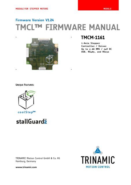
<strong>Firmware</strong> Version V1.24<br />
<strong>TMCL</strong> FIRMWARE MANUAL<br />
+ + <strong>TMCM</strong>-<strong>1161</strong><br />
+ +<br />
UNIQUE FEATURES:<br />
TRINAMIC Motion Control GmbH & Co. KG<br />
Hamburg, Germany<br />
www.trinamic.com<br />
1-Axis Stepper<br />
Controller / Driver<br />
Up to 2.8A RMS / 24V DC<br />
USB, RS485, and RS232
<strong>TMCM</strong>-<strong>1161</strong> <strong>TMCL</strong> <strong>Firmware</strong> V1.24 <strong>Manual</strong> (Rev. 1.05 / 2013-MAR-27) 2<br />
Table of Contents<br />
1 Features ........................................................................................................................................................................... 4<br />
2 Putting the Module into Operation ........................................................................................................................ 6<br />
2.1 Basic Set-Up .......................................................................................................................................................... 6<br />
2.1.1 Connecting the module ............................................................................................................................... 6<br />
2.1.2 Start the <strong>TMCL</strong>-IDE Software Development Environment ................................................................. 8<br />
2.2 Using <strong>TMCL</strong> Direct Mode .................................................................................................................................... 9<br />
2.2.1 Important Motor Settings ......................................................................................................................... 10<br />
2.3 Testing with a Simple <strong>TMCL</strong> Program ......................................................................................................... 11<br />
3 <strong>TMCL</strong> and the <strong>TMCL</strong>-IDE: Introduction ................................................................................................................. 12<br />
3.1 Binary Command Format ................................................................................................................................ 12<br />
3.1.1 Checksum Calculation ................................................................................................................................ 13<br />
3.2 Reply Format ....................................................................................................................................................... 13<br />
3.2.1 Status Codes ................................................................................................................................................. 14<br />
3.3 Standalone Applications .................................................................................................................................. 14<br />
3.4 <strong>TMCL</strong> Command Overview .............................................................................................................................. 15<br />
3.4.1 <strong>TMCL</strong> Commands ......................................................................................................................................... 15<br />
3.4.2 Commands Listed According to Subject Area .................................................................................... 16<br />
3.5 Commands ........................................................................................................................................................... 20<br />
3.5.1 ROR (rotate right) ........................................................................................................................................ 20<br />
3.5.2 ROL (rotate left) ........................................................................................................................................... 21<br />
3.5.3 MST (motor stop)......................................................................................................................................... 22<br />
3.5.4 MVP (move to position) ............................................................................................................................ 23<br />
3.5.5 SAP (set axis parameter) ........................................................................................................................... 24<br />
3.5.6 GAP (get axis parameter) .......................................................................................................................... 25<br />
3.5.7 STAP (store axis parameter) ..................................................................................................................... 26<br />
3.5.8 RSAP (restore axis parameter) ................................................................................................................. 27<br />
3.5.9 SGP (set global parameter) ...................................................................................................................... 28<br />
3.5.10 GGP (get global parameter)...................................................................................................................... 29<br />
3.5.11 STGP (store global parameter) ................................................................................................................ 30<br />
3.5.12 RSGP (restore global parameter) ............................................................................................................ 31<br />
3.5.13 RFS (reference search) ................................................................................................................................ 32<br />
3.5.14 SIO (set input / output) ............................................................................................................................. 33<br />
3.5.15 GIO (get input /output) ............................................................................................................................. 35<br />
3.5.16 CALC (calculate) ............................................................................................................................................ 37<br />
3.5.17 COMP (compare)........................................................................................................................................... 38<br />
3.5.18 JC (jump conditional) ................................................................................................................................. 39<br />
3.5.19 JA (jump always) ......................................................................................................................................... 40<br />
3.5.20 CSUB (call subroutine) ............................................................................................................................... 41<br />
3.5.21 RSUB (return from subroutine) ................................................................................................................ 42<br />
3.5.22 WAIT (wait for an event to occur) ......................................................................................................... 43<br />
3.5.23 STOP (stop <strong>TMCL</strong> program execution) ................................................................................................... 44<br />
3.5.24 CALCX (calculate using the X register) .................................................................................................. 45<br />
3.5.25 AAP (accumulator to axis parameter) .................................................................................................... 46<br />
3.5.26 AGP (accumulator to global parameter) ............................................................................................... 47<br />
3.5.27 CLE (clear error flags) ................................................................................................................................. 48<br />
3.5.28 VECT (set interrupt vector) ........................................................................................................................ 49<br />
3.5.29 EI (enable interrupt) ................................................................................................................................... 50<br />
3.5.30 DI (disable interrupt) .................................................................................................................................. 51<br />
3.5.31 RETI (return from interrupt) ..................................................................................................................... 52<br />
3.5.32 Customer specific <strong>TMCL</strong> command extension (UF0… UF7/user function) .................................... 53<br />
3.5.33 Request target position reached event ................................................................................................ 53<br />
3.5.34 <strong>TMCL</strong> Control Functions ............................................................................................................................. 54<br />
4 Axis parameters .......................................................................................................................................................... 56<br />
4.1 stallGuard2 ........................................................................................................................................................... 63<br />
4.2 coolStep Related Axis Parameters ................................................................................................................ 63<br />
5 Global parameters ...................................................................................................................................................... 65<br />
www.trinamic.com
<strong>TMCM</strong>-<strong>1161</strong> <strong>TMCL</strong> <strong>Firmware</strong> V1.24 <strong>Manual</strong> (Rev. 1.05 / 2013-MAR-27) 3<br />
5.1 Bank 0 ................................................................................................................................................................... 65<br />
5.2 Bank 1 ................................................................................................................................................................... 67<br />
5.3 Bank 2 ................................................................................................................................................................... 67<br />
5.4 Bank 3 ................................................................................................................................................................... 68<br />
6 Hints and Tips ............................................................................................................................................................. 69<br />
6.1 Reference Search ............................................................................................................................................... 69<br />
6.2 Changing the Prescaler Value of an Encoder ............................................................................................ 72<br />
6.3 Using the RS485 Interface .............................................................................................................................. 72<br />
7 Life Support Policy ..................................................................................................................................................... 73<br />
8 Revision History .......................................................................................................................................................... 74<br />
8.1 <strong>Firmware</strong> Revision ............................................................................................................................................ 74<br />
8.2 Document Revision ........................................................................................................................................... 74<br />
9 References .................................................................................................................................................................... 74<br />
www.trinamic.com
<strong>TMCM</strong>-<strong>1161</strong> <strong>TMCL</strong> <strong>Firmware</strong> V1.24 <strong>Manual</strong> (Rev. 1.05 / 2013-MAR-27) 4<br />
1 Features<br />
The <strong>TMCM</strong>-<strong>1161</strong> is a single axis controller/driver module for 2-phase bipolar stepper motors with state of<br />
the art feature set. It is highly integrated, offers a convenient handling and can be used in many<br />
decentralized applications. The board can be mounted on the back of NEMA23 (57mm flange size) and<br />
NEMA24 (60mm flange size) stepper motors and has been designed for coil currents up to 2.8A RMS and<br />
24V DC supply voltage. It offers TRINAMICs sensOstep encoder. With its high energy efficiency from the<br />
coolStep technology cost for power consumption is kept down. The <strong>TMCL</strong> firmware allows for both,<br />
standalone operation and direct mode.<br />
MAIN CHARACTERISTICS<br />
Motion controller<br />
Motion profile calculation in real-time<br />
On the fly alteration of motor parameters (e.g. position, velocity, acceleration)<br />
High performance microcontroller for overall system control and serial communication protocol<br />
handling<br />
Bipolar stepper motor driver<br />
Up to 256 microsteps per full step<br />
High-efficient operation, low power dissipation<br />
Dynamic current control<br />
Integrated protection<br />
stallGuard2 feature for stall detection<br />
coolStep feature for reduced power consumption and heat dissipation<br />
Encoder<br />
sensOstep magnetic encoder (max. 1024 positions per rotation) e.g. for step-loss detection under all<br />
operating conditions and positioning supervision<br />
Interfaces<br />
inputs for stop switches (left and right) and home switch<br />
1 analog input<br />
2 general purpose outputs (open collector with freewheeling diodes)<br />
USB, RS232, and RS485 communication interfaces<br />
Software<br />
<strong>TMCL</strong>: standalone operation or remote controlled operation,<br />
program memory (non volatile) for up to 2048 <strong>TMCL</strong> commands, and<br />
PC-based application development software <strong>TMCL</strong>-IDE available for free.<br />
Electrical and mechanical data<br />
Supply voltage: +24V DC nominal (10… 30V DC)<br />
Motor current: up to 2.8A RMS (programmable)<br />
Refer to separate Hardware <strong>Manual</strong>, too.<br />
www.trinamic.com
<strong>TMCM</strong>-<strong>1161</strong> <strong>TMCL</strong> <strong>Firmware</strong> V1.24 <strong>Manual</strong> (Rev. 1.05 / 2013-MAR-27) 5<br />
TRINAMICS UNIQUE FEATURES – EASY TO USE WITH <strong>TMCL</strong><br />
stallGuard2 stallGuard2 is a high-precision sensorless load measurement using the back EMF on the<br />
coils. It can be used for stall detection as well as other uses at loads below those which<br />
stall the motor. The stallGuard2 measurement value changes linearly over a wide range of<br />
load, velocity, and current settings. At maximum motor load, the value goes to zero or<br />
near to zero. This is the most energy-efficient point of operation for the motor.<br />
www.trinamic.com<br />
Load<br />
[Nm]<br />
Max. load<br />
Figure 1.1 stallGuard2 load measurement SG as a function of load<br />
stallGuard2<br />
Initial stallGuard2<br />
(SG) value: 100%<br />
stallGuard2 (SG) value: 0<br />
Maximum load reached.<br />
Motor close to stall.<br />
Motor stalls<br />
coolStep coolStep is a load-adaptive automatic current scaling based on the load measurement via<br />
stallGuard2 adapting the required current to the load. Energy consumption can be reduced<br />
by as much as 75%. coolStep allows substantial energy savings, especially for motors<br />
which see varying loads or operate at a high duty cycle. Because a stepper motor<br />
application needs to work with a torque reserve of 30% to 50%, even a constant-load<br />
application allows significant energy savings because coolStep automatically enables<br />
torque reserve when required. Reducing power consumption keeps the system cooler,<br />
increases motor life, and allows reducing cost.<br />
0,9<br />
0,8<br />
0,7<br />
0,6<br />
0,5<br />
Efficiency<br />
0,4<br />
0,3<br />
0,2<br />
0,1<br />
0<br />
0 50 100 150 200 250 300 350<br />
Velocity [RPM]<br />
Figure 1.2 Energy efficiency example with coolStep<br />
Efficiency with coolStep<br />
Efficiency with 50% torque reserve
<strong>TMCM</strong>-<strong>1161</strong> <strong>TMCL</strong> <strong>Firmware</strong> V1.24 <strong>Manual</strong> (Rev. 1.05 / 2013-MAR-27) 6<br />
2 Putting the Module into Operation<br />
Here you can find basic information for putting your <strong>TMCM</strong>-<strong>1161</strong> into operation. If you are already common<br />
with TRINAMICs modules you may skip this chapter.<br />
The things you need:<br />
<strong>TMCM</strong>-<strong>1161</strong> with fitting motor<br />
Interface (RS232/RS485/USB) suitable to your module with cables<br />
Nominal supply voltage +24V DC for your module<br />
<strong>TMCL</strong>-IDE program and PC<br />
PRECAUTIONS<br />
Do not connect or disconnect the <strong>TMCM</strong>-<strong>1161</strong> while powered!<br />
Do not connect or disconnect the motor while powered!<br />
Do not exceed the maximum power supply voltage of 30V DC!<br />
Note, that the module is not protected against reverse polarity!<br />
START WITH POWER SUPPLY OFF!<br />
2.1 Basic Set-Up<br />
The following paragraph will guide you through the steps of connecting the unit and making first<br />
movements with the motor.<br />
2.1.1 Connecting the module<br />
RS485<br />
Converter<br />
e.g. USB-2-485<br />
RS232<br />
Pin 6 RS232_RXD<br />
Pin 5 RS232_TXD<br />
RS485<br />
Pin 4 RS485-<br />
Pin 3 RS485+<br />
Pin 1 GND<br />
Power supply<br />
Pin 2 10… 30V DC<br />
Pin 1 GND<br />
Note, that the<br />
GND pin has to<br />
be used for the<br />
power supply<br />
and for the RS485<br />
interface, too.<br />
www.trinamic.com<br />
USB<br />
1<br />
Interface<br />
Stepper<br />
motor<br />
Figure 2.1: Starting up<br />
RS232<br />
1<br />
1<br />
Motor<br />
In/Out<br />
Pin 1 A1<br />
Pin 2 A2<br />
Pin 3 A3<br />
Pin 4 A4<br />
USB<br />
USB<br />
Serial USB<br />
interface<br />
1
<strong>TMCM</strong>-<strong>1161</strong> <strong>TMCL</strong> <strong>Firmware</strong> V1.24 <strong>Manual</strong> (Rev. 1.05 / 2013-MAR-27) 7<br />
1. Connect power supply and choose your interface<br />
a) Connect RS232 or RS485 and power supply<br />
Pin Label Description<br />
1 GND Module and signal ground<br />
2 VCC 10… 30V DC power supply / nom. 24V DC<br />
3 RS485A+ RS485 non-inverted bus signal<br />
4 RS485B- RS485 inverted bus signal<br />
5 RS232_TxD RS232 transmit data from module<br />
6 RS232_RxD RS232 receive data to module<br />
b) Connect USB interface (as alternative to RS232 and RS485; use a normal USB cable)<br />
Download and install the file <strong>TMCM</strong>-<strong>1161</strong>.inf (www.trinamic.com).<br />
Pin Label Description<br />
1 VBUS +5V power<br />
2 D- Data –<br />
3 D+ Data +<br />
4 ID Not connected<br />
5 GND ground<br />
2. Connect motor<br />
Pin Label Description<br />
1 OA1 Motor coil A<br />
2 OA2 Motor coil A<br />
3 OB1 Motor coil B<br />
4 OB2 Motor coil B<br />
3. Connect In/Out connector<br />
If you like to work with the GPIOs, switches or the step/dir interface, use the In/Out connector.<br />
www.trinamic.com<br />
Pin Label Description<br />
1 GND Module ground (system and signal ground)<br />
2 VCC 10… 30V DC power supply / nom. 24V DC<br />
3 OUT_0 General purpose output, open collector<br />
4 OUT_1 General purpose output, open collector<br />
5 AIN_0 Analog input, 0… 10V (analog to digital converter range)<br />
6<br />
7<br />
8<br />
STOP_L/<br />
STEP/<br />
IN_1<br />
STOP_R/<br />
DIR/<br />
IN_2<br />
HOME/<br />
ENABLE/<br />
IN_3<br />
Digital input, +24V compatible, programmable internal pull-up.*<br />
Functionality can be selected in software:<br />
a) Left stop switch input (connected to REF1 input of TMC429 motion<br />
controller)<br />
b) Step signal (connected to step input of TMC262 stepper driver)<br />
c) General purpose input (connected to processor)<br />
Digital input +24V compatible, programmable internal pull-up.*<br />
Functionality can be selected in software:<br />
a) Right stop switch input (connected to REFR1 input of TMC429 motion<br />
controller)<br />
b) Direction signal (connected to direction input of TMC262 stepper driver)<br />
c) General purpose input (connected to processor)<br />
Digital input +24V compatible, programmable internal pull-up.*<br />
Functionality can be chosen in software:<br />
a) Home switch input (connected to processor)<br />
b) Enable signal (connected to processor)<br />
c) General purpose input (connected to processor)
<strong>TMCM</strong>-<strong>1161</strong> <strong>TMCL</strong> <strong>Firmware</strong> V1.24 <strong>Manual</strong> (Rev. 1.05 / 2013-MAR-27) 8<br />
4. Switch ON the power supply<br />
Turn power ON. The green LED for power lights up slowly and the motor is powered but in<br />
standstill now.<br />
If this does not occur, switch power OFF and check your connections as well as the power<br />
supply.<br />
2.1.2 Start the <strong>TMCL</strong>-IDE Software Development Environment<br />
The <strong>TMCL</strong>-IDE is available on www.trinamic.com.<br />
Installing the <strong>TMCL</strong>-IDE:<br />
Make sure the COM port you intend to use is not blocked by another program.<br />
Open <strong>TMCL</strong>-IDE by clicking <strong>TMCL</strong>.exe.<br />
Choose Setup and Options and thereafter the Connection tab.<br />
Choose COM port and type with the parameters shown in Figure 2.2 (baud rate 9600). Click OK.<br />
USB interface<br />
If the file <strong>TMCM</strong>-<strong>1161</strong>.inf is installed correctly, the module will be identified automatically.<br />
Figure 2.2 Setup dialogue and connection tab of the <strong>TMCL</strong>-IDE.<br />
Please refer to the <strong>TMCL</strong>-IDE User <strong>Manual</strong> for more information (see www.TRINAMIC.com).<br />
www.trinamic.com
<strong>TMCM</strong>-<strong>1161</strong> <strong>TMCL</strong> <strong>Firmware</strong> V1.24 <strong>Manual</strong> (Rev. 1.05 / 2013-MAR-27) 9<br />
2.2 Using <strong>TMCL</strong> Direct Mode<br />
1. Start <strong>TMCL</strong> Direct Mode.<br />
www.trinamic.com<br />
Direct Mode<br />
2. If the communication is established the <strong>TMCM</strong>-<strong>1161</strong> is automatically detected. If the module is not<br />
detected, please check all points above (cables, interface, power supply, COM port, baud rate).<br />
3. Issue a command by choosing Instruction, Type (if necessary), Motor, and Value and click<br />
Execute to send it to the module.<br />
Examples:<br />
ROR rotate right, motor 0, value 500 -> Click Execute. The first motor is rotating now.<br />
MST motor stop, motor 0 -> Click Execute. The first motor stops now.<br />
Top right of the <strong>TMCL</strong> Direct Mode window is the button Copy to editor. Click here to copy the chosen<br />
command and create your own <strong>TMCL</strong> program. The command will be shown immediately on the editor.<br />
NOTE<br />
Please mind chapter 3 (programming techniques) of the <strong>TMCL</strong>-IDE User <strong>Manual</strong> on www.trinamic.com.<br />
Here you will find information about creating general structures of <strong>TMCL</strong> programs. In particular<br />
initialization, main loop, symbolic constants, variables, and subroutines are described there. Further you<br />
can learn how to mix direct mode and stand alone mode.<br />
Chapter 4 of this manual (axis parameters) includes a diagram which points out the coolStep related axis<br />
parameters and their functions. This can help you configuring your module to meet your needs.
<strong>TMCM</strong>-<strong>1161</strong> <strong>TMCL</strong> <strong>Firmware</strong> V1.24 <strong>Manual</strong> (Rev. 1.05 / 2013-MAR-27) 10<br />
2.2.1 Important Motor Settings<br />
There are some axis parameters which have to be adjusted right in the beginning after installing your<br />
module. Please set the upper limiting values for the speed (axis parameter 4), the acceleration (axis<br />
parameter 5), and the current (axis parameter 6). Further set the standby current (axis parameter 7) and<br />
choose your microstep resolution with axis parameter 140. Please use the SAP (Set Axis Parameter)<br />
command for adjusting these values. The SAP command is described in paragraph 3.5.5. You can use the<br />
<strong>TMCM</strong>-IDE direct mode for easily configuring your module.<br />
ATTENTION<br />
The most important motor setting is the absolute maximum motor current setting, since too high values<br />
might cause motor damage!<br />
IMPORTANT AXIS PARAMETERS FOR MOTOR SETTING<br />
Number Axis Parameter Description Range [Unit]<br />
4 Maximum Should not exceed the physically highest possible 0… 2047<br />
positioning value. Adjust the pulse divisor (axis parameter 154), if<br />
speed<br />
the speed value is very low (
<strong>TMCM</strong>-<strong>1161</strong> <strong>TMCL</strong> <strong>Firmware</strong> V1.24 <strong>Manual</strong> (Rev. 1.05 / 2013-MAR-27) 11<br />
2.3 Testing with a Simple <strong>TMCL</strong> Program<br />
Type in the following program:<br />
Assemble<br />
www.trinamic.com<br />
ROL 0, 500 //Rotate motor 0 with speed 500<br />
WAIT TICKS, 0, 500<br />
MST 0<br />
ROR 0, 500 //Rotate motor 0 with 500<br />
WAIT TICKS, 0, 500<br />
MST 0<br />
SAP 4, 0, 500 //Set max. Velocity<br />
SAP 5, 0, 50 //Set max. Acceleration<br />
Loop: MVP ABS, 0, 10000 //Move to Position 10000<br />
WAIT POS, 0, 0 //Wait until position reached<br />
MVP ABS, 0, -10000 //Move to Position -10000<br />
WAIT POS, 0, 0 //Wait until position reached<br />
JA Loop //Infinite Loop<br />
Download Run<br />
1. Click the Assemble icon to convert the <strong>TMCL</strong> into machine code.<br />
2. Then download the program to the <strong>TMCM</strong>-<strong>1161</strong> module by clicking the Download icon.<br />
3. Press icon Run. The desired program will be executed.<br />
4. Click the Stop button to stop the program.<br />
Stop
<strong>TMCM</strong>-<strong>1161</strong> <strong>TMCL</strong> <strong>Firmware</strong> V1.24 <strong>Manual</strong> (Rev. 1.05 / 2013-MAR-27) 12<br />
3 <strong>TMCL</strong> and the <strong>TMCL</strong>-IDE: Introduction<br />
As with most TRINAMIC modules the software running on the microprocessor of the <strong>TMCM</strong>-<strong>1161</strong> consists<br />
of two parts, a boot loader and the firmware itself. Whereas the boot loader is installed during production<br />
and testing at TRINAMIC and remains untouched throughout the whole lifetime, the firmware can be<br />
updated by the user. New versions can be downloaded free of charge from the TRINAMIC website<br />
(http://www.trinamic.com).<br />
The <strong>TMCM</strong>-<strong>1161</strong> supports <strong>TMCL</strong> direct mode (binary commands) and standalone <strong>TMCL</strong> program execution.<br />
You can store up to 2048 <strong>TMCL</strong> instructions on it.<br />
In direct mode and most cases the <strong>TMCL</strong> communication over RS485, RS232, or USB follows a strict<br />
master/slave relationship. That is, a host computer (e.g. PC/PLC) acting as the interface bus master will<br />
send a command to the <strong>TMCL</strong>-<strong>1161</strong>. The <strong>TMCL</strong> interpreter on the module will then interpret this command,<br />
do the initialization of the motion controller, read inputs and write outputs or whatever is necessary<br />
according to the specified command. As soon as this step has been done, the module will send a reply<br />
back over RS485/RS232/USB to the bus master. Only then should the master transfer the next command.<br />
Normally, the module will just switch to transmission and occupy the bus for a reply, otherwise it will stay<br />
in receive mode. It will not send any data over the interface without receiving a command first. This way,<br />
any collision on the bus will be avoided when there are more than two nodes connected to a single bus.<br />
The <strong>Trinamic</strong> Motion Control Language [<strong>TMCL</strong>] provides a set of structured motion control commands.<br />
Every motion control command can be given by a host computer or can be stored in an EEPROM on the<br />
<strong>TMCM</strong> module to form programs that run standalone on the module. For this purpose there are not only<br />
motion control commands but also commands to control the program structure (like conditional jumps,<br />
compare and calculating).<br />
Every command has a binary representation and a mnemonic. The binary format is used to send<br />
commands from the host to a module in direct mode, whereas the mnemonic format is used for easy<br />
usage of the commands when developing standalone <strong>TMCL</strong> applications using the <strong>TMCL</strong>-IDE (IDE means<br />
Integrated Development Environment).<br />
There is also a set of configuration variables for the axis and for global parameters which allow individual<br />
configuration of nearly every function of a module. This manual gives a detailed description of all <strong>TMCL</strong><br />
commands and their usage.<br />
3.1 Binary Command Format<br />
Every command has a mnemonic and a binary representation. When commands are sent from a host to a<br />
module, the binary format has to be used. Every command consists of a one-byte command field, a onebyte<br />
type field, a one-byte motor/bank field and a four-byte value field. So the binary representation of a<br />
command always has seven bytes. When a command is to be sent via RS232, RS485 or USB interface, it<br />
has to be enclosed by an address byte at the beginning and a checksum byte at the end. In this case it<br />
consists of nine bytes.<br />
The binary command format for RS232/RS485/USB is as follows:<br />
Bytes Meaning<br />
1 Module address<br />
1 Command number<br />
1 Type number<br />
1 Motor or Bank number<br />
4 Value (MSB first!)<br />
1 Checksum<br />
The checksum is calculated by adding up all the other bytes using an 8-bit addition.<br />
www.trinamic.com
<strong>TMCM</strong>-<strong>1161</strong> <strong>TMCL</strong> <strong>Firmware</strong> V1.24 <strong>Manual</strong> (Rev. 1.05 / 2013-MAR-27) 13<br />
3.1.1 Checksum Calculation<br />
As mentioned above, the checksum is calculated by adding up all bytes (including the module address<br />
byte) using 8-bit addition. Here are two examples to show how to do this:<br />
in C:<br />
unsigned char i, Checksum;<br />
unsigned char Command[9];<br />
//Set the “Command” array to the desired command<br />
Checksum = Command[0];<br />
for(i=1; i
<strong>TMCM</strong>-<strong>1161</strong> <strong>TMCL</strong> <strong>Firmware</strong> V1.24 <strong>Manual</strong> (Rev. 1.05 / 2013-MAR-27) 14<br />
3.2.1 Status Codes<br />
The reply contains a status code. The status code can have one of the following values:<br />
Code Meaning<br />
100 Successfully executed, no error<br />
101 Command loaded into <strong>TMCL</strong><br />
program EEPROM<br />
1 Wrong checksum<br />
2 Invalid command<br />
3 Wrong type<br />
4 Invalid value<br />
5 Configuration EEPROM locked<br />
6 Command not available<br />
3.3 Standalone Applications<br />
The module is equipped with a <strong>TMCL</strong> memory for storing <strong>TMCL</strong> applications. You can use <strong>TMCL</strong>-IDE for<br />
developing standalone <strong>TMCL</strong> applications. You can download a program into the EEPROM and afterwards it<br />
will run on the module. The <strong>TMCL</strong>-IDE contains an editor and the <strong>TMCL</strong> assembler where the commands<br />
can be entered using their mnemonic format. They will be assembled automatically into their binary<br />
representations. Afterwards this code can be downloaded into the module to be executed there.<br />
www.trinamic.com
<strong>TMCM</strong>-<strong>1161</strong> <strong>TMCL</strong> <strong>Firmware</strong> V1.24 <strong>Manual</strong> (Rev. 1.05 / 2013-MAR-27) 15<br />
3.4 <strong>TMCL</strong> Command Overview<br />
In this section a short overview of the <strong>TMCL</strong> commands is given.<br />
3.4.1 <strong>TMCL</strong> Commands<br />
Command Number Parameter Description<br />
ROR 1 , Rotate right with specified velocity<br />
ROL 2 , Rotate left with specified velocity<br />
MST 3 Stop motor movement<br />
MVP 4 ABS|REL|COORD, ,<br />
<br />
Move to position (absolute or relative)<br />
SAP 5 , , Set axis parameter (motion control<br />
specific settings)<br />
GAP 6 , Get axis parameter (read out motion<br />
control specific settings)<br />
STAP 7 , Store axis parameter permanently (non<br />
volatile)<br />
RSAP 8 , Restore axis parameter<br />
SGP 9 , , value Set global parameter (module specific<br />
settings e.g. communication settings<br />
or <strong>TMCL</strong> user variables)<br />
GGP 10 , Get global parameter (read out module<br />
specific settings e.g. communication<br />
settings or <strong>TMCL</strong> user variables)<br />
STGP 11 , Store global parameter (<strong>TMCL</strong> user<br />
variables only)<br />
RSGP 12 , Restore global parameter (<strong>TMCL</strong> user<br />
variable only)<br />
RFS 13 START|STOP|STATUS, Reference search<br />
SIO 14 , , Set digital output to specified value<br />
GIO 15 , Get value of analogue/digital input<br />
CALC 19 , Process accumulator & value<br />
COMP 20 Compare accumulator value<br />
JC 21 , Jump conditional<br />
JA 22 Jump absolute<br />
CSUB 23 Call subroutine<br />
RSUB 24 Return from subroutine<br />
EI 25 Enable interrupt<br />
DI 26 Disable interrupt<br />
WAIT 27 , , Wait with further program execution<br />
STOP 28 Stop program execution<br />
SCO 30 , ,<br />
<br />
Set coordinate<br />
GCO 31 , Get coordinate<br />
CCO 32 , Capture coordinate<br />
CALCX 33 Process accumulator & X-register<br />
AAP 34 , Accumulator to axis parameter<br />
AGP 35 , Accumulator to global parameter<br />
VECT 37 , Set interrupt vector<br />
RETI 38 Return from interrupt<br />
ACO 39 , Accu to coordinate<br />
www.trinamic.com
<strong>TMCM</strong>-<strong>1161</strong> <strong>TMCL</strong> <strong>Firmware</strong> V1.24 <strong>Manual</strong> (Rev. 1.05 / 2013-MAR-27) 16<br />
3.4.2 Commands Listed According to Subject Area<br />
3.4.2.1 Motion Commands<br />
These commands control the motion of the motor. They are the most important commands and can be<br />
used in direct mode or in standalone mode.<br />
Mnemonic Command number Meaning<br />
ROL 2 Rotate left<br />
ROR 1 Rotate right<br />
MVP 4 Move to position<br />
MST 3 Motor stop<br />
RFS 13 Reference search<br />
SCO 30 Store coordinate<br />
CCO 32 Capture coordinate<br />
GCO 31 Get coordinate<br />
3.4.2.2 Parameter Commands<br />
These commands are used to set, read and store axis parameters or global parameters. Axis parameters<br />
can be set independently for each axis, whereas global parameters control the behavior of the module<br />
itself. These commands can also be used in direct mode and in standalone mode.<br />
Mnemonic Command number Meaning<br />
SAP 5 Set axis parameter<br />
GAP 6 Get axis parameter<br />
STAP 7 Store axis parameter into EEPROM<br />
RSAP 8 Restore axis parameter from EEPROM<br />
SGP 9 Set global parameter<br />
GGP 10 Get global parameter<br />
STGP 11 Store global parameter into EEPROM<br />
RSGP 12 Restore global parameter from EEPROM<br />
3.4.2.3 Control Commands<br />
These commands are used to control the program flow (loops, conditions, jumps etc.). It does not make<br />
sense to use them in direct mode. They are intended for standalone mode only.<br />
Mnemonic Command number Meaning<br />
JA 22 Jump always<br />
JC 21 Jump conditional<br />
COMP 20 Compare accumulator with constant<br />
value<br />
CSUB 23 Call subroutine<br />
RSUB 24 Return from subroutine<br />
WAIT 27 Wait for a specified event<br />
STOP 28 End of a <strong>TMCL</strong> program<br />
3.4.2.4 I/O Port Commands<br />
These commands control the external I/O ports and can be used in direct mode and in standalone mode.<br />
Mnemonic Command number Meaning<br />
SIO 14 Set output<br />
GIO 15 Get input<br />
www.trinamic.com
<strong>TMCM</strong>-<strong>1161</strong> <strong>TMCL</strong> <strong>Firmware</strong> V1.24 <strong>Manual</strong> (Rev. 1.05 / 2013-MAR-27) 17<br />
3.4.2.5 Calculation Commands<br />
These commands are intended to be used for calculations within <strong>TMCL</strong> applications. Although they could<br />
also be used in direct mode it does not make much sense to do so.<br />
Mnemonic Command number Meaning<br />
CALC 19 Calculate using the accumulator and a<br />
constant value<br />
CALCX 33 Calculate using the accumulator and the<br />
X register<br />
AAP 34 Copy accumulator to an axis parameter<br />
AGP 35 Copy accumulator to a global parameter<br />
ACO 39 Copy accu to coordinate<br />
For calculating purposes there is an accumulator (or accu or A register) and an X register. When executed<br />
in a <strong>TMCL</strong> program (in standalone mode), all <strong>TMCL</strong> commands that read a value store the result in the<br />
accumulator. The X register can be used as an additional memory when doing calculations. It can be<br />
loaded from the accumulator.<br />
When a command that reads a value is executed in direct mode the accumulator will not be affected. This<br />
means that while a <strong>TMCL</strong> program is running on the module (standalone mode), a host can still send<br />
commands like GAP and GGP to the module (e.g. to query the actual position of the motor) without<br />
affecting the flow of the <strong>TMCL</strong> program running on the module.<br />
3.4.2.6 Interrupt Commands<br />
Due to some customer requests, interrupt processing has been introduced in the <strong>TMCL</strong> firmware for ARM<br />
based modules.<br />
Mnemonic Command number Meaning<br />
EI 25 Enable interrupt<br />
DI 26 Disable interrupt<br />
VECT 37 Set interrupt vector<br />
RETI 38 Return from interrupt<br />
3.4.2.6.1 Interrupt Types<br />
There are many different interrupts in <strong>TMCL</strong>, like timer interrupts, stop switch interrupts, position reached<br />
interrupts, and input pin change interrupts. Each of these interrupts has its own interrupt vector. Each<br />
interrupt vector is identified by its interrupt number. Please use the <strong>TMCL</strong> included file Interrupts.inc for<br />
symbolic constants of the interrupt numbers.<br />
3.4.2.6.2 Interrupt Processing<br />
When an interrupt occurs and this interrupt is enabled and a valid interrupt vector has been defined for<br />
that interrupt, the normal <strong>TMCL</strong> program flow will be interrupted and the interrupt handling routine will<br />
be called. Before an interrupt handling routine gets called, the context of the normal program will be<br />
saved automatically (i.e. accumulator register, X register, <strong>TMCL</strong> flags).<br />
There is no interrupt nesting, i.e. all other interrupts are disabled while an interrupt handling routine is<br />
being executed.<br />
On return from an interrupt handling routine, the context of the normal program will automatically be<br />
restored and the execution of the normal program will be continued.<br />
www.trinamic.com
<strong>TMCM</strong>-<strong>1161</strong> <strong>TMCL</strong> <strong>Firmware</strong> V1.24 <strong>Manual</strong> (Rev. 1.05 / 2013-MAR-27) 18<br />
3.4.2.6.3 Interrupt Vectors<br />
The following table shows all interrupt vectors that can be used.<br />
Interrupt number Interrupt type<br />
0 Timer 0<br />
1 Timer 1<br />
2 Timer 2<br />
3 Target position reached<br />
15 stallGuard2<br />
21 Deviation<br />
27 Left stop switch<br />
28 Right stop switch<br />
39 Input change 0<br />
40 Input change 1<br />
41 Input change 2<br />
42 Input change 3<br />
255 Global interrupts<br />
3.4.2.6.4 Further Configuration of Interrupts<br />
Some interrupts need further configuration (e.g. the timer interval of a timer interrupt). This can be done<br />
using SGP commands with parameter bank 3 (SGP , 3, ). Please refer to the SGP command<br />
(paragraph 3.5.9) for further information about that.<br />
3.4.2.6.5 Using Interrupts in <strong>TMCL</strong><br />
For using an interrupt proceed as follows:<br />
Define an interrupt handling routine using the VECT command.<br />
If necessary, configure the interrupt using an SGP , 3, command.<br />
Enable the interrupt using an EI command.<br />
Globally enable interrupts using an EI 255 command.<br />
An interrupt handling routine must always end with a RETI command<br />
The following example shows the use of a timer interrupt:<br />
VECT 0, Timer0Irq //define the interrupt vector<br />
SGP 0, 3, 1000 //configure the interrupt: set its period to 1000ms<br />
EI 0 //enable this interrupt<br />
EI 255 //globally switch on interrupt processing<br />
//Main program: toggles output 3, using a WAIT command for the delay<br />
Loop:<br />
SIO 3, 2, 1<br />
WAIT TICKS, 0, 50<br />
SIO 3, 2, 0<br />
WAIT TICKS, 0, 50<br />
JA Loop<br />
//Here is the interrupt handling routine<br />
Timer0Irq:<br />
GIO 0, 2 //check if OUT0 is high<br />
JC NZ, Out0Off //jump if not<br />
SIO 0, 2, 1 //switch OUT0 high<br />
RETI //end of interrupt<br />
Out0Off:<br />
SIO 0, 2, 0 //switch OUT0 low<br />
RETI //end of interrupt<br />
www.trinamic.com
<strong>TMCM</strong>-<strong>1161</strong> <strong>TMCL</strong> <strong>Firmware</strong> V1.24 <strong>Manual</strong> (Rev. 1.05 / 2013-MAR-27) 19<br />
In the example above, the interrupt numbers are used directly. To make the program better readable use<br />
the provided include file Interrupts.inc. This file defines symbolic constants for all interrupt numbers which<br />
can be used in all interrupt commands. The beginning of the program above then looks like the following:<br />
#include Interrupts.inc<br />
VECT TI_TIMER0, Timer0Irq<br />
SGP TI_TIMER0, 3, 1000<br />
EI TI_TIMER0<br />
EI TI_GLOBAL<br />
Please also take a look at the other example programs.<br />
www.trinamic.com
<strong>TMCM</strong>-<strong>1161</strong> <strong>TMCL</strong> <strong>Firmware</strong> V1.24 <strong>Manual</strong> (Rev. 1.05 / 2013-MAR-27) 20<br />
3.5 Commands<br />
The module specific commands are explained in more detail on the following pages. They are listed<br />
according to their command number.<br />
3.5.1 ROR (rotate right)<br />
With this command the motor will be instructed to rotate with a specified velocity in right direction<br />
(increasing the position counter).<br />
Internal function: First, velocity mode is selected. Then, the velocity value is transferred to axis parameter<br />
#0 (target velocity).<br />
The module is based on the TMC429 stepper motor controller and the TMC262 power driver. This makes<br />
possible choosing a velocity between 0 and 2047.<br />
Related commands: ROL, MST, SAP, GAP<br />
Mnemonic: ROR 0, <br />
Binary representation:<br />
INSTRUCTION NO. TYPE MOT/BANK VALUE<br />
1 (don't care) 0* <br />
0… 2047<br />
*motor number is always O as only one motor is involved<br />
Reply in direct mode:<br />
STATUS VALUE<br />
www.trinamic.com<br />
100 – OK (don't care)<br />
Example:<br />
Rotate right, velocity = 350<br />
Mnemonic: ROR 0, 350<br />
Binary:<br />
Byte Index 0 1 2 3 4 5 6 7<br />
Function Target- Instruction Type Motor/ Operand Operand Operand Operand<br />
address Number<br />
Bank Byte3 Byte2 Byte1 Byte0<br />
Value (hex) $01 $01 $00 $00 $00 $00 $01 $5e
<strong>TMCM</strong>-<strong>1161</strong> <strong>TMCL</strong> <strong>Firmware</strong> V1.24 <strong>Manual</strong> (Rev. 1.05 / 2013-MAR-27) 21<br />
3.5.2 ROL (rotate left)<br />
With this command the motor will be instructed to rotate with a specified velocity (opposite direction<br />
compared to ROR, decreasing the position counter).<br />
Internal function: First, velocity mode is selected. Then, the velocity value is transferred to axis parameter<br />
#0 (target velocity).<br />
The module is based on the TMC429 stepper motor controller and the TMC262 power driver. This makes<br />
possible choosing a velocity between 0 and 2047.<br />
Related commands: ROR, MST, SAP, GAP<br />
Mnemonic: ROL 0, <br />
Binary representation:<br />
INSTRUCTION NO. TYPE MOT/BANK VALUE<br />
2 (don't care) 0* <br />
0… 2047<br />
*motor number is always O as only one motor is involved<br />
Reply in direct mode:<br />
STATUS VALUE<br />
www.trinamic.com<br />
100 – OK (don't care)<br />
Example:<br />
Rotate left, velocity = 1200<br />
Mnemonic: ROL 0, 1200<br />
Binary:<br />
Byte Index 0 1 2 3 4 5 6 7<br />
Function Target- Instruction Type Motor/ Operand Operand Operand Operand<br />
address Number<br />
Bank Byte3 Byte2 Byte1 Byte0<br />
Value (hex) $01 $02 $00 $00 $00 $00 $04 $b0
<strong>TMCM</strong>-<strong>1161</strong> <strong>TMCL</strong> <strong>Firmware</strong> V1.24 <strong>Manual</strong> (Rev. 1.05 / 2013-MAR-27) 22<br />
3.5.3 MST (motor stop)<br />
With this command the motor will be instructed to stop with a soft stop.<br />
Internal function: The axis parameter target velocity is set to zero.<br />
Related commands: ROL, ROR, SAP, GAP<br />
Mnemonic: MST 0<br />
Binary representation:<br />
INSTRUCTION NO. TYPE MOT/BANK VALUE<br />
www.trinamic.com<br />
3 (don't care) 0* (don't care)<br />
*motor number is always O as only one motor is involved<br />
Reply in direct mode:<br />
STATUS VALUE<br />
Example:<br />
Stop motor<br />
Mnemonic: MST 0<br />
100 – OK (don't care)<br />
Binary:<br />
Byte Index 0 1 2 3 4 5 6 7<br />
Function Target- Instruction Type Motor/ Operand Operand Operand Operand<br />
address Number<br />
Bank Byte3 Byte2 Byte1 Byte0<br />
Value (hex) $01 $03 $00 $00 $00 $00 $00 $00
<strong>TMCM</strong>-<strong>1161</strong> <strong>TMCL</strong> <strong>Firmware</strong> V1.24 <strong>Manual</strong> (Rev. 1.05 / 2013-MAR-27) 23<br />
3.5.4 MVP (move to position)<br />
With this command the motor will be instructed to move to a specified relative or absolute position. It<br />
will use the acceleration/deceleration ramp and the positioning speed programmed into the unit. This<br />
command is non-blocking – that is, a reply will be sent immediately after command interpretation and<br />
initialization of the motion controller. Further commands may follow without waiting for the motor<br />
reaching its end position. The maximum velocity and acceleration are defined by axis parameters #4 and<br />
#5.<br />
The range of the MVP command is 32 bit signed (−2.147.483.648… +2.147.483.647). Positioning can be<br />
interrupted using MST, ROL or ROR commands.<br />
Two operation types are available:<br />
Moving to an absolute position in the range from −2.147.483.648… +2.147.483.647 (-2 31 … 2 31 -1).<br />
Starting a relative movement by means of an offset to the actual position. In this case, the new<br />
resulting position value must not exceed the above mentioned limits, too.<br />
Please note, that the distance between the actual position and the new one should not be more than<br />
2 31 -1 microsteps. Otherwise the motor will run in the opposite direction in order to take the shorter<br />
distance.<br />
Internal function: A new position value is transferred to the axis parameter #2 target position”.<br />
Related commands: SAP, GAP, and MST<br />
Mnemonic: MVP , 0, <br />
Binary representation:<br />
INSTRUCTION NO. TYPE MOT/BANK VALUE<br />
4 0 ABS – absolute 0* <br />
www.trinamic.com<br />
1 REL – relative 0 <br />
*motor number is always O as only one motor is involved<br />
Reply in direct mode:<br />
STATUS VALUE<br />
100 – OK (don't care)<br />
Example:<br />
Move motor to (absolute) position 90000<br />
Mnemonic: MVP ABS, 0, 9000<br />
Binary:<br />
Byte Index 0 1 2 3 4 5 6 7<br />
Function Target- Instruction Type Motor/ Operand Operand Operand Operand<br />
address Number<br />
Bank Byte3 Byte2 Byte1 Byte0<br />
Value (hex) $01 $04 $00 $00 $00 $01 $5f $90<br />
Example:<br />
Move motor from current position 1000 steps backward (move relative -1000)<br />
Mnemonic: MVP REL, 0, -1000<br />
Binary:<br />
Byte Index 0 1 2 3 4 5 6 7<br />
Function Target- Instruction Type Motor/ Operand Operand Operand Operand<br />
address Number<br />
Bank Byte3 Byte2 Byte1 Byte0<br />
Value (hex) $01 $04 $01 $00 $ff $ff $fc $18
<strong>TMCM</strong>-<strong>1161</strong> <strong>TMCL</strong> <strong>Firmware</strong> V1.24 <strong>Manual</strong> (Rev. 1.05 / 2013-MAR-27) 24<br />
3.5.5 SAP (set axis parameter)<br />
With this command most of the motion control parameters of the module can be specified. The settings<br />
will be stored in SRAM and therefore are volatile. That is, information will be lost after power off. Please<br />
use command STAP (store axis parameter) in order to store any setting permanently.<br />
For a table with parameters and values which can be used together with this command please refer to<br />
chapter 4.<br />
Internal function: The parameter format is converted ignoring leading zeros (or ones for negative values).<br />
The parameter is transferred to the correct position in the appropriate device.<br />
Related commands: GAP, STAP, RSAP, AAP<br />
Mnemonic: SAP , 0, <br />
Binary representation:<br />
INSTRUCTION NO. TYPE MOT/BANK VALUE<br />
5 <br />
*motor number is always O as only one motor is involved<br />
Reply in direct mode:<br />
STATUS VALUE<br />
www.trinamic.com<br />
100 – OK (don't care)<br />
Example:<br />
Set the absolute maximum current of motor to 200mA<br />
Mnemonic: SAP 6, 0, 200<br />
0* <br />
Binary:<br />
Byte Index 0 1 2 3 4 5 6 7<br />
Function Target- Instruction Type Motor/ Operand Operand Operand Operand<br />
address Number<br />
Bank Byte3 Byte2 Byte1 Byte0<br />
Value (hex) $01 $05 $06 $00 $00 $00 $00 $c8
<strong>TMCM</strong>-<strong>1161</strong> <strong>TMCL</strong> <strong>Firmware</strong> V1.24 <strong>Manual</strong> (Rev. 1.05 / 2013-MAR-27) 25<br />
3.5.6 GAP (get axis parameter)<br />
Most parameters of the <strong>TMCM</strong>-<strong>1161</strong> can be adjusted individually for the axis. With this parameter they can<br />
be read out. In standalone mode the requested value is also transferred to the accumulator register for<br />
further processing purposes (such as conditioned jumps). In direct mode the value read is only output in<br />
the value field of the reply (without affecting the accumulator).<br />
For a table with parameters and values which can be used together with this command please refer to<br />
chapter 4.<br />
Internal function: The parameter is read out of the correct position in the appropriate device. The<br />
parameter format is converted adding leading zeros (or ones for negative values).<br />
Related commands: SAP, STAP, AAP, RSAP<br />
Mnemonic: GAP , 0<br />
Binary representation:<br />
INSTRUCTION NO. TYPE MOT/BANK VALUE<br />
www.trinamic.com<br />
6 0* (don't care)<br />
*motor number is always O as only one motor is involved<br />
Reply in direct mode:<br />
STATUS VALUE<br />
100 – OK (don't care)<br />
Example:<br />
Get the actual position of motor<br />
Mnemonic: GAP 0, 1<br />
Binary:<br />
Byte Index 0 1 2 3 4 5 6 7<br />
Function Target- Instruction Type Motor/ Operand Operand Operand Operand<br />
address Number<br />
Bank Byte3 Byte2 Byte1 Byte0<br />
Value (hex) $01 $06 $01 $00 $00 $00 $00 $00<br />
Reply:<br />
Byte Index 0 1 2 3 4 5 6 7<br />
Function Host- Target- Status Instructio Operand Operand Operand Operand<br />
address address<br />
n Byte3 Byte2 Byte1 Byte0<br />
Value (hex) $02 $01 $64 $06 $00 $00 $02 $c7<br />
status=no error, position=711
<strong>TMCM</strong>-<strong>1161</strong> <strong>TMCL</strong> <strong>Firmware</strong> V1.24 <strong>Manual</strong> (Rev. 1.05 / 2013-MAR-27) 26<br />
3.5.7 STAP (store axis parameter)<br />
An axis parameter previously set with a Set Axis Parameter command (SAP) will be stored permanent. Most<br />
parameters are automatically restored after power up (refer to axis parameter list in chapter 4).<br />
For a table with parameters and values which can be used together with this command please refer to<br />
chapter 4.<br />
Internal function: An axis parameter value stored in SRAM will be transferred to EEPROM and loaded from<br />
EEPORM after next power up.<br />
Related commands: SAP, RSAP, GAP, AAP<br />
Mnemonic: STAP , 0<br />
Binary representation:<br />
INSTRUCTION NO. TYPE MOT/BANK VALUE<br />
www.trinamic.com<br />
7 0* 1 (don't care)* 2<br />
* 1 motor number is always O as only one motor is involved<br />
* 2 the value operand of this function has no effect. Instead, the currently used value (e.g. selected by SAP) is saved.<br />
Reply in direct mode:<br />
STATUS VALUE<br />
100 – OK (don't care)<br />
Parameter ranges:<br />
Parameter number Motor number Value<br />
s. chapter 4 0 s. chapter 4<br />
Example:<br />
Store the maximum speed of motor<br />
Mnemonic: STAP 4, 0<br />
Binary:<br />
Byte Index 0 1 2 3 4 5 6 7<br />
Function Target- Instruction Type Motor/ Operand Operand Operand Operand<br />
address Number<br />
Bank Byte3 Byte2 Byte1 Byte0<br />
Value (hex) $01 $07 $04 $00 $00 $00 $00 $00<br />
Note: The STAP command will not have any effect when the configuration EEPROM is locked (refer to 5.1).<br />
In direct mode, the error code 5 (configuration EEPROM locked, see also section 3.2.1) will be returned in<br />
this case.
<strong>TMCM</strong>-<strong>1161</strong> <strong>TMCL</strong> <strong>Firmware</strong> V1.24 <strong>Manual</strong> (Rev. 1.05 / 2013-MAR-27) 27<br />
3.5.8 RSAP (restore axis parameter)<br />
For all configuration-related axis parameters non-volatile memory locations are provided. By default, most<br />
parameters are automatically restored after power up (refer to axis parameter list in chapter 4). A single<br />
parameter that has been changed before can be reset by this instruction also.<br />
For a table with parameters and values which can be used together with this command please refer to<br />
chapter 4.<br />
Internal function: The specified parameter is copied from the configuration EEPROM memory to its RAM<br />
location.<br />
Relate commands: SAP, STAP, GAP, and AAP<br />
Mnemonic: RSAP , 0<br />
Binary representation:<br />
INSTRUCTION NO. TYPE MOT/BANK VALUE<br />
www.trinamic.com<br />
8 0* (don't care)<br />
*motor number is always O as only one motor is involved<br />
Reply structure in direct mode:<br />
STATUS VALUE<br />
100 – OK (don't care)<br />
Example:<br />
Restore the maximum current of motor<br />
Mnemonic: RSAP 6, 0<br />
Binary:<br />
Byte Index 0 1 2 3 4 5 6 7<br />
Function Target- Instruction Type Motor/ Operand Operand Operand Operand<br />
address Number<br />
Bank Byte3 Byte2 Byte1 Byte0<br />
Value (hex) $01 $08 $06 $00 $00 $00 $00 $00
<strong>TMCM</strong>-<strong>1161</strong> <strong>TMCL</strong> <strong>Firmware</strong> V1.24 <strong>Manual</strong> (Rev. 1.05 / 2013-MAR-27) 28<br />
3.5.9 SGP (set global parameter)<br />
With this command most of the module specific parameters not directly related to motion control can be<br />
specified and the <strong>TMCL</strong> user variables can be changed. Global parameters are related to the host interface,<br />
peripherals or application specific variables. The different groups of these parameters are organized in<br />
banks to allow a larger total number for future products. Currently, only bank 0 and 1 are used for global<br />
parameters, and bank 2 is used for user variables.<br />
All module settings will automatically be stored non-volatile (internal EEPROM of the processor). The<br />
<strong>TMCL</strong> user variables will not be stored in the EEPROM automatically, but this can be done by using<br />
STGP commands.<br />
For a table with parameters and bank numbers which can be used together with this command please<br />
refer to chapter 5.<br />
Internal function: the parameter format is converted ignoring leading zeros (or ones for negative values).<br />
The parameter is transferred to the correct position in the appropriate (on board) device.<br />
Related commands: GGP, STGP, RSGP, AGP<br />
Mnemonic: SGP , , <br />
Binary representation:<br />
INSTRUCTION NO. TYPE MOT/BANK VALUE<br />
www.trinamic.com<br />
9 <br />
Reply in direct mode:<br />
STATUS VALUE<br />
100 – OK (don't care)<br />
Example:<br />
Set the serial address of the target device to 3<br />
Mnemonic: SGP 66, 0, 3<br />
<br />
Binary:<br />
Byte Index 0 1 2 3 4 5 6 7<br />
Function Target- Instruction Type Motor/ Operand Operand Operand Operand<br />
address Number<br />
Bank Byte3 Byte2 Byte1 Byte0<br />
Value (hex) $01 $09 $42 $00 $00 $00 $00 $03
<strong>TMCM</strong>-<strong>1161</strong> <strong>TMCL</strong> <strong>Firmware</strong> V1.24 <strong>Manual</strong> (Rev. 1.05 / 2013-MAR-27) 29<br />
3.5.10 GGP (get global parameter)<br />
All global parameters can be read with this function. Global parameters are related to the host interface,<br />
peripherals or application specific variables. The different groups of these parameters are organized in<br />
banks to allow a larger total number for future products. Currently, only bank 0 and 1 are used for global<br />
parameters, and bank 2 is used for user variables.<br />
For a table with parameters and bank numbers which can be used together with this command please<br />
refer to chapter 5.<br />
Internal function: The parameter is read out of the correct position in the appropriate device. The<br />
parameter format is converted adding leading zeros (or ones for negative values).<br />
Related commands: SGP, STGP, RSGP, AGP<br />
Mnemonic: GGP , <br />
Binary representation:<br />
INSTRUCTION NO. TYPE MOT/BANK VALUE<br />
www.trinamic.com<br />
10 (see chapter 6) (don't care)<br />
Reply in direct mode:<br />
STATUS VALUE<br />
100 – OK (don't care)<br />
Example:<br />
Get the serial address of the target device<br />
Mnemonic: GGP 66, 0<br />
Binary:<br />
Byte Index 0 1 2 3 4 5 6 7<br />
Function Target- Instruction Type Motor/ Operand Operand Operand Operand<br />
address Number<br />
Bank Byte3 Byte2 Byte1 Byte0<br />
Value (hex) $01 $0a $42 $00 $00 $00 $00 $00<br />
Reply:<br />
Byte Index 0 1 2 3 4 5 6 7<br />
Function Host- Target- Status Instructio Operand Operand Operand Operand<br />
address address<br />
n Byte3 Byte2 Byte1 Byte0<br />
Value (hex) $02 $01 $64 $0a $00 $00 $00 $01<br />
Status=no error, Value=1
<strong>TMCM</strong>-<strong>1161</strong> <strong>TMCL</strong> <strong>Firmware</strong> V1.24 <strong>Manual</strong> (Rev. 1.05 / 2013-MAR-27) 30<br />
3.5.11 STGP (store global parameter)<br />
This command is used to store <strong>TMCL</strong> user variables permanently in the EEPROM of the module. Some<br />
global parameters are located in RAM memory, so without storing modifications are lost at power down.<br />
This instruction enables enduring storing. Most parameters are automatically restored after power up.<br />
For a table with parameters and bank numbers which can be used together with this command please<br />
refer to chapter 5.<br />
Internal function: The specified parameter is copied from its RAM location to the configuration EEPROM.<br />
Related commands: SGP, GGP, RSGP, AGP<br />
Mnemonic: STGP , <br />
Binary representation:<br />
INSTRUCTION NO. TYPE MOT/BANK VALUE<br />
www.trinamic.com<br />
11 (see chapter 8) <br />
(see chapter 5)<br />
Reply in direct mode:<br />
STATUS VALUE<br />
100 – OK (don't care)<br />
Example:<br />
Store the user variable #42<br />
Mnemonic: STGP 42, 2<br />
(don't care)<br />
Binary:<br />
Byte Index 0 1 2 3 4 5 6 7<br />
Function Target- Instruction Type Motor/ Operand Operand Operand Operand<br />
address Number<br />
Bank Byte3 Byte2 Byte1 Byte0<br />
Value (hex) $01 $0b $2a $02 $00 $00 $00 $00
<strong>TMCM</strong>-<strong>1161</strong> <strong>TMCL</strong> <strong>Firmware</strong> V1.24 <strong>Manual</strong> (Rev. 1.05 / 2013-MAR-27) 31<br />
3.5.12 RSGP (restore global parameter)<br />
With this command the contents of a <strong>TMCL</strong> user variable can be restored from the EEPROM. For all<br />
configuration-related axis parameters, non-volatile memory locations are provided. By default, most<br />
parameters are automatically restored after power up. A single parameter that has been changed before<br />
can be reset by this instruction.<br />
For a table with parameters and bank numbers which can be used together with this command please<br />
refer to chapter 5.<br />
Internal function: The specified parameter is copied from the configuration EEPROM memory to its RAM<br />
location.<br />
Relate commands: SAP, STAP, GAP, and AAP<br />
Mnemonic: RSAP , 0<br />
Binary representation:<br />
INSTRUCTION NO. TYPE MOT/BANK VALUE<br />
www.trinamic.com<br />
8 0* (don't care)<br />
*motor number is always O if only one motor is involved<br />
Reply structure in direct mode:<br />
STATUS VALUE<br />
100 – OK (don't care)<br />
Example:<br />
Restore the maximum current of motor<br />
Mnemonic: RSGP 6, 0<br />
Binary:<br />
Byte Index 0 1 2 3 4 5 6 7<br />
Function Target- Instruction Type Motor/ Operand Operand Operand Operand<br />
address Number<br />
Bank Byte3 Byte2 Byte1 Byte0<br />
Value (hex) $01 $0c $2a $02 $00 $00 $00 $00
<strong>TMCM</strong>-<strong>1161</strong> <strong>TMCL</strong> <strong>Firmware</strong> V1.24 <strong>Manual</strong> (Rev. 1.05 / 2013-MAR-27) 32<br />
3.5.13 RFS (reference search)<br />
The <strong>TMCM</strong>-<strong>1161</strong> has a built-in reference search algorithm which can be used. The reference search<br />
algorithm provides switching point calibration and three switch modes. The status of the reference search<br />
can also be queried to see if it has already finished. (In a <strong>TMCL</strong> program it is better to use the WAIT<br />
command to wait for the end of a reference search.) Please see the appropriate parameters in the axis<br />
parameter table to configure the reference search algorithm to meet your needs (chapter 4). The reference<br />
search can be started, stopped, and the actual status of the reference search can be checked.<br />
Internal function: the reference search is implemented as a state machine, so interaction is possible<br />
during execution.<br />
Related commands: WAIT<br />
Mnemonic: RFS , <br />
Binary representation:<br />
INSTRUCTION NO. TYPE MOT/BANK VALUE<br />
13<br />
REPLY IN DIRECT MODE:<br />
www.trinamic.com<br />
0 START – start ref. search<br />
1 STOP – abort ref. search<br />
2 STATUS – get status<br />
When using type 0 (START) or 1 (STOP):<br />
STATUS VALUE<br />
100 – OK don’t care<br />
When using type 2 (STATUS):<br />
STATUS VALUE<br />
100 – OK 0 ref. search active<br />
other values no ref. search<br />
active<br />
Example:<br />
Start reference search of motor 0<br />
Mnemonic: RFS START, 0<br />
0<br />
see below<br />
Binary:<br />
Byte Index 0 1 2 3 4 5 6 7<br />
Function Target- Instruction Type Motor/ Operand Operand Operand Operand<br />
address Number<br />
Bank Byte3 Byte2 Byte1 Byte0<br />
Value (hex) $01 $0d $00 $00 $00 $00 $00 $00<br />
With this module it is possible to use stall detection instead of a reference search.
<strong>TMCM</strong>-<strong>1161</strong> <strong>TMCL</strong> <strong>Firmware</strong> V1.24 <strong>Manual</strong> (Rev. 1.05 / 2013-MAR-27) 33<br />
3.5.14 SIO (set input / output)<br />
- SIO sets the status of the general digital output either to low (0) or to high (1). Bank 2 is used for<br />
this purpose.<br />
- SIO is used to switch the pull-up resistors for all digital inputs ON (1) and OFF (0). Bank 0 is used<br />
for this purpose.<br />
Internal function: the passed value is transferred to the specified output line.<br />
Related commands: GIO, WAIT<br />
Mnemonic: SIO , , <br />
Binary representation:<br />
INSTRUCTION NO. TYPE MOT/BANK VALUE<br />
14 <br />
<br />
2<br />
0/1<br />
Reply structure:<br />
STATUS VALUE<br />
100 – OK don’t care<br />
Example:<br />
Set OUT_2 to high (bank 2, output 2)<br />
Mnemonic: SIO 2, 2, 1<br />
Binary:<br />
Byte Index 0 1 2 3 4 5 6 7<br />
Function Target- Instruction Type Motor/ Operand Operand Operand Operand<br />
address Number<br />
Bank Byte3 Byte2 Byte1 Byte0<br />
Value (hex) $01 $0e $07 $02 $00 $00 $00 $01<br />
1<br />
Interface<br />
Motor<br />
www.trinamic.com<br />
In/Out<br />
Figure 3.1 Connectors<br />
1<br />
1<br />
USB<br />
I/O PORTS USED FOR SIO AND COMMAND<br />
Pin I/O port Command Range<br />
3 OUT_0 SIO 0, 2, 1/0<br />
4 OUT_1 SIO 1, 2, 1/0<br />
1
<strong>TMCM</strong>-<strong>1161</strong> <strong>TMCL</strong> <strong>Firmware</strong> V1.24 <strong>Manual</strong> (Rev. 1.05 / 2013-MAR-27) 34<br />
ADDRESSING BOTH OUTPUT LINES WITH ONE SIO COMMAND:<br />
- Set the type parameter to 255 and the bank parameter to 2.<br />
- The value parameter must then be set to a value between 0… 255, where every bit represents one<br />
output line.<br />
- Furthermore, the value can also be set to -1. In this special case, the contents of the lower 8 bits<br />
of the accumulator are copied to the output pins.<br />
Example:<br />
Set all output pins high.<br />
Mnemonic: SIO 255, 2, 3<br />
THE FOLLOWING PROGRAM WILL SHOW THE STATES OF THE INPUT LINES ON THE OUTPUT LINES:<br />
Loop: GIO 255, 0<br />
SIO 255, 2,-1<br />
JA Loop<br />
SPECIAL COMMAND FOR SWITCHING THE PULL-UP RESISTORS FOR STOP_L, STOP_R, AND HOME<br />
Pin I/O port Command Range<br />
5<br />
6<br />
7<br />
STOP_L / IN_1<br />
STOP_R / IN_2<br />
HOME / IN_3<br />
www.trinamic.com<br />
SIO 0, 0, 1/0<br />
1: ON<br />
0: OFF
<strong>TMCM</strong>-<strong>1161</strong> <strong>TMCL</strong> <strong>Firmware</strong> V1.24 <strong>Manual</strong> (Rev. 1.05 / 2013-MAR-27) 35<br />
3.5.15 GIO (get input /output)<br />
With this command the status of all general purpose inputs of the module can be read out. The function<br />
reads a digital or analogue input port. Digital lines will read 0 and 1, while the ADC channels deliver their<br />
12 bit result in the range of 0… 4095.<br />
GIO IN STANDALONE MODE<br />
In standalone mode the requested value is copied to the accumulator (accu) for further processing<br />
purposes such as conditioned jumps.<br />
GIO IN DIRECT MODE<br />
In direct mode the value is only output in the value field of the reply, without affecting the accumulator.<br />
The actual status of a digital output line can also be read.<br />
Internal function: the specified line is read.<br />
Related commands: SIO, WAIT<br />
Mnemonic: GIO , <br />
Binary representation:<br />
INSTRUCTION NO. TYPE MOT/BANK VALUE<br />
www.trinamic.com<br />
15 don’t care<br />
Reply in direct mode:<br />
STATUS VALUE<br />
100 – OK <br />
Example:<br />
Get the analogue value of ADC channel 0<br />
Mnemonic: GIO 0, 1<br />
Binary:<br />
Byte Index 0 1 2 3 4 5 6 7<br />
Function Target- Instruction Type Motor/ Operand Operand Operand Operand<br />
address Number<br />
Bank Byte3 Byte2 Byte1 Byte0<br />
Value (hex) $01 $0f $00 $01 $00 $00 $00 $00<br />
Reply:<br />
Byte Index 0 1 2 3 4 5 6 7<br />
Function Host- Target- Status Instructio Operand Operand Operand Operand<br />
address address<br />
n Byte3 Byte2 Byte1 Byte0<br />
Value (hex) $02 $01 $64 $0f $00 $00 $01 $2e<br />
Status = no error, value = 320
<strong>TMCM</strong>-<strong>1161</strong> <strong>TMCL</strong> <strong>Firmware</strong> V1.24 <strong>Manual</strong> (Rev. 1.05 / 2013-MAR-27) 36<br />
1<br />
Interface<br />
Motor<br />
www.trinamic.com<br />
1<br />
1<br />
In/Out<br />
Figure 3.2 Connectors<br />
3.5.15.1 I/O Bank 0 – Digital Inputs<br />
USB<br />
1<br />
The ADIN lines can be read as digital or analogue inputs at the same time. The analogue values can<br />
be accessed in bank 1.<br />
Pin I/O port Command Range<br />
5 IN_0 GIO 0, 0 0/1<br />
6 IN_1 GIO 1, 0, 0/1<br />
7 IN_2 GIO 2, 0, 0/1<br />
8 IN_3 GIO 3, 0, 0/1<br />
FURTHER READ-OUT COMMANDS<br />
I/O port<br />
S/D ENABLE input<br />
Command<br />
0 active<br />
1 off<br />
GIO 12, 0<br />
Limited performance because of<br />
double seizure of I/O port.<br />
READING ALL DIGITAL INPUTS WITH ONE GIO COMMAND:<br />
- Set the type parameter to 255 and the bank parameter to 0.<br />
- In this case the status of all digital input lines will be read to the lower eight bits of the<br />
accumulator.<br />
USE FOLLOWING PROGRAM TO REPRESENT THE STATES OF THE INPUT LINES ON THE OUTPUT LINES:<br />
Loop: GIO 255, 0<br />
SIO 255, 2,-1<br />
JA Loop<br />
3.5.15.2 I/O Bank 1 – Analogue Inputs<br />
The ADIN lines can be read back as digital or analogue inputs at the same time. The digital states<br />
can be accessed in bank 0.<br />
Pin I/O port Command Range<br />
5 IN_0 GIO 0, 1, 0… 4095<br />
READ OUT OPERATING VOLTAGE AND TEMPERATURE<br />
I/O port Command<br />
Operating voltage [1/10 V] GIO 8, 1<br />
Temperature [˚C] GIO 9, 1
<strong>TMCM</strong>-<strong>1161</strong> <strong>TMCL</strong> <strong>Firmware</strong> V1.24 <strong>Manual</strong> (Rev. 1.05 / 2013-MAR-27) 37<br />
3.5.15.3 I/O Bank 2 –States of Digital Outputs<br />
The states of the OUT lines (that have been set by SIO commands) can be read back using bank 2.<br />
Pin I/O port Command Range<br />
3 OUT_0 GIO 0, 2, 1/0<br />
4 OUT_1 GIO 1, 2, 1/0<br />
3.5.16 CALC (calculate)<br />
A value in the accumulator variable, previously read by a function such as GAP (get axis parameter) can be<br />
modified with this instruction. Nine different arithmetic functions can be chosen and one constant operand<br />
value must be specified. The result is written back to the accumulator, for further processing like<br />
comparisons or data transfer.<br />
Related commands: CALCX, COMP, JC, AAP, AGP, GAP, GGP<br />
Mnemonic: CALC , <br />
where is ADD, SUB, MUL, DIV, MOD, AND, OR, XOR, NOT or LOAD<br />
Binary representation:<br />
INSTRUCTION NO. TYPE MOT/BANK VALUE<br />
www.trinamic.com<br />
19 0 ADD – add to accu<br />
1 SUB – subtract from accu<br />
2 MUL – multiply accu by<br />
3 DIV – divide accu by<br />
4 MOD – modulo divide by<br />
5 AND – logical and accu with<br />
6 OR – logical or accu with<br />
7 XOR – logical exor accu with<br />
8 NOT – logical invert accu<br />
9 LOAD – load operand to accu<br />
Example:<br />
Multiply accu by -5000<br />
Mnemonic: CALC MUL, -5000<br />
(don't care) <br />
Binary:<br />
Byte Index 0 1 2 3 4 5 6 7<br />
Function Target- Instruction Type Motor/ Operand Operand Operand Operand<br />
address Number<br />
Bank Byte3 Byte2 Byte1 Byte0<br />
Value (hex) $01 $13 $02 $00 $FF $FF $EC $78
<strong>TMCM</strong>-<strong>1161</strong> <strong>TMCL</strong> <strong>Firmware</strong> V1.24 <strong>Manual</strong> (Rev. 1.05 / 2013-MAR-27) 38<br />
3.5.17 COMP (compare)<br />
The specified number is compared to the value in the accumulator register. The result of the comparison<br />
can for example be used by the conditional jump (JC) instruction. This command is intended for use in<br />
standalone operation only.<br />
The host address and the reply are only used to take the instruction to the <strong>TMCL</strong> program memory<br />
while the program loads down. It does not make sense to use this command in direct mode.<br />
Internal function: The specified value is compared to the internal accumulator, which holds the value of a<br />
preceding get or calculate instruction (see GAP/GGP/ CALC/CALCX). The internal arithmetic status flags are<br />
set according to the comparison result.<br />
Related commands: JC (jump conditional), GAP, GGP, CALC, CALCX<br />
Mnemonic: COMP <br />
Binary representation:<br />
INSTRUCTION NO. TYPE MOT/BANK VALUE<br />
www.trinamic.com<br />
20 (don't care) (don't care) <br />
Example:<br />
Jump to the address given by the label when the position of motor is greater than or equal to<br />
1000.<br />
GAP 1, 2, 0 //get axis parameter, type: no. 1 (actual position), motor: 0, value: 0 (don't care)<br />
COMP 1000 //compare actual value to 1000<br />
JC GE, Label //jump, type: 5 greater/equal, the label must be defined somewhere else in the<br />
program<br />
Binary format of the COMP 1000 command:<br />
Byte Index 0 1 2 3 4 5 6 7<br />
Function Target- Instruction Type Motor/ Operand Operand Operand Operand<br />
address Number<br />
Bank Byte3 Byte2 Byte1 Byte0<br />
Value (hex) $01 $14 $00 $00 $00 $00 $03 $e8
<strong>TMCM</strong>-<strong>1161</strong> <strong>TMCL</strong> <strong>Firmware</strong> V1.24 <strong>Manual</strong> (Rev. 1.05 / 2013-MAR-27) 39<br />
3.5.18 JC (jump conditional)<br />
The JC instruction enables a conditional jump to a fixed address in the <strong>TMCL</strong> program memory, if the<br />
specified condition is met. The conditions refer to the result of a preceding comparison. Please refer to<br />
COMP instruction for examples. This function is for standalone operation only.<br />
The host address and the reply are only used to take the instruction to the <strong>TMCL</strong> program memory<br />
while the program loads down. It does not make sense to use this command in direct mode. See the<br />
host-only control functions for details.<br />
Internal function: the <strong>TMCL</strong> program counter is set to the passed value if the arithmetic status flags are in<br />
the appropriate state(s).<br />
Related commands: JA, COMP, WAIT, CLE<br />
Mnemonic: JC , <br />
where =ZE|NZ|EQ|NE|GT|GE|LT|LE|ETO|EAL|EDV|EPO<br />
Binary representation:<br />
INSTRUCTION NO. TYPE MOT/BANK VALUE<br />
www.trinamic.com<br />
21 0 ZE - zero<br />
1 NZ - not zero<br />
2 EQ - equal<br />
3 NE - not equal<br />
4 GT - greater<br />
5 GE - greater/equal<br />
6 LT - lower<br />
7 LE - lower/equal<br />
8 ETO - time out error<br />
9 EAL – external alarm<br />
12 ESD – shutdown error<br />
(don't care) <br />
Example:<br />
Jump to address given by the label when the position of motor is greater than or equal to 1000.<br />
GAP 1, 0, 0 //get axis parameter, type: no. 1 (actual position), motor: 0, value: 0 (don't care)<br />
COMP 1000 //compare actual value to 1000<br />
JC GE, Label //jump, type: 5 greater/equal<br />
...<br />
...<br />
Label: ROL 0, 1000<br />
Binary format of JC GE, Label when Label is at address 10:<br />
Byte Index 0 1 2 3 4 5 6 7<br />
Function Target- Instruction Type Motor/ Operand Operand Operand Operand<br />
address Number<br />
Bank Byte3 Byte2 Byte1 Byte0<br />
Value (hex) $01 $15 $05 $00 $00 $00 $00 $0a
<strong>TMCM</strong>-<strong>1161</strong> <strong>TMCL</strong> <strong>Firmware</strong> V1.24 <strong>Manual</strong> (Rev. 1.05 / 2013-MAR-27) 40<br />
3.5.19 JA (jump always)<br />
Jump to a fixed address in the <strong>TMCL</strong> program memory. This command is intended for standalone operation<br />
only.<br />
The host address and the reply are only used to take the instruction to the <strong>TMCL</strong> program memory<br />
while the program loads down. This command cannot be used in direct mode.<br />
Internal function: the <strong>TMCL</strong> program counter is set to the passed value.<br />
Related commands: JC, WAIT, CSUB<br />
Mnemonic: JA <br />
Binary representation:<br />
INSTRUCTION NO. TYPE MOT/BANK VALUE<br />
www.trinamic.com<br />
22 (don't care) (don't care) <br />
Example: An infinite loop in <strong>TMCL</strong><br />
Loop: MVP ABS, 0, 10000<br />
WAIT POS, 0, 0<br />
MVP ABS, 0, 0<br />
WAIT POS, 0, 0<br />
JA Loop //Jump to the label Loop<br />
Binary format of JA Loop assuming that the label Loop is at address 20:<br />
Byte Index 0 1 2 3 4 5 6 7<br />
Function Target- Instruction Type Motor/ Operand Operand Operand Operand<br />
address Number<br />
Bank Byte3 Byte2 Byte1 Byte0<br />
Value (hex) $01 $16 $00 $00 $00 $00 $00 $14
<strong>TMCM</strong>-<strong>1161</strong> <strong>TMCL</strong> <strong>Firmware</strong> V1.24 <strong>Manual</strong> (Rev. 1.05 / 2013-MAR-27) 41<br />
3.5.20 CSUB (call subroutine)<br />
This function calls a subroutine in the <strong>TMCL</strong> program memory. It is intended for standalone operation only.<br />
The host address and the reply are only used to take the instruction to the <strong>TMCL</strong> program memory<br />
while the program loads down. This command cannot be used in direct mode.<br />
Internal function: The actual <strong>TMCL</strong> program counter value is saved to an internal stack, afterwards<br />
overwritten with the passed value. The number of entries in the internal stack is limited to 8. This also<br />
limits nesting of subroutine calls to 8. The command will be ignored if there is no more stack space left.<br />
Related commands: RSUB, JA<br />
Mnemonic: CSUB <br />
Binary representation:<br />
INSTRUCTION NO. TYPE MOT/BANK VALUE<br />
www.trinamic.com<br />
23 (don't care) (don't care) <br />
Example: Call a subroutine<br />
Loop: MVP ABS, 0, 10000<br />
CSUB SubW //Save program counter and jump to label SubW<br />
MVP ABS, 0, 0<br />
JA Loop<br />
SubW: WAIT POS, 0, 0<br />
WAIT TICKS, 0, 50<br />
RSUB //Continue with the command following the CSUB command<br />
Binary format of the CSUB SubW command assuming that the label SubW is at address 100:<br />
Byte Index 0 1 2 3 4 5 6 7<br />
Function Target- Instruction Type Motor/ Operand Operand Operand Operand<br />
address Number<br />
Bank Byte3 Byte2 Byte1 Byte0<br />
Value (hex) $01 $17 $00 $00 $00 $00 $00 $64
<strong>TMCM</strong>-<strong>1161</strong> <strong>TMCL</strong> <strong>Firmware</strong> V1.24 <strong>Manual</strong> (Rev. 1.05 / 2013-MAR-27) 42<br />
3.5.21 RSUB (return from subroutine)<br />
Return from a subroutine to the command after the CSUB command. This command is intended for use in<br />
standalone mode only.<br />
The host address and the reply are only used to take the instruction to the <strong>TMCL</strong> program memory<br />
while the program loads down. This command cannot be used in direct mode.<br />
Internal function: The <strong>TMCL</strong> program counter is set to the last value of the stack. The command will be<br />
ignored if the stack is empty.<br />
Related command: CSUB<br />
Mnemonic: RSUB<br />
Binary representation:<br />
INSTRUCTION NO. TYPE MOT/BANK VALUE<br />
www.trinamic.com<br />
24 (don't care) (don't care) (don't care)<br />
Example: please see the CSUB example (section 3.5.20).<br />
Binary format of RSUB:<br />
Byte Index 0 1 2 3 4 5 6 7<br />
Function Target- Instruction Type Motor/ Operand Operand Operand Operand<br />
address Number<br />
Bank Byte3 Byte2 Byte1 Byte0<br />
Value (hex) $01 $18 $00 $00 $00 $00 $00 $00
<strong>TMCM</strong>-<strong>1161</strong> <strong>TMCL</strong> <strong>Firmware</strong> V1.24 <strong>Manual</strong> (Rev. 1.05 / 2013-MAR-27) 43<br />
3.5.22 WAIT (wait for an event to occur)<br />
This instruction interrupts the execution of the <strong>TMCL</strong> program until the specified condition is met. This<br />
command is intended for standalone operation only.<br />
The host address and the reply are only used to take the instruction to the <strong>TMCL</strong> program memory<br />
while the program loads down. This command cannot be used in direct mode.<br />
There are five different wait conditions that can be used:<br />
TICKS: Wait until the number of timer ticks specified by the parameter has been<br />
reached.<br />
POS: Wait until the target position of the motor specified by the parameter has been<br />
reached. An optional timeout value (0 for no timeout) must be specified by the <br />
parameter.<br />
REFSW: Wait until the reference switch of the motor specified by the parameter has<br />
been triggered. An optional timeout value (0 for no timeout) must be specified by the <br />
parameter.<br />
LIMSW: Wait until a limit switch of the motor specified by the parameter has been<br />
triggered. An optional timeout value (0 for no timeout) must be specified by the <br />
parameter.<br />
RFS: Wait until the reference search of the motor specified by the field has been<br />
reached. An optional timeout value (0 for no timeout) must be specified by the <br />
parameter.<br />
The timeout flag (ETO) will be set after a timeout limit has been reached. You can then use a JC ETO<br />
command to check for such errors or clear the error using the CLE command.<br />
Internal function: The <strong>TMCL</strong> program counter is held until the specified condition is met.<br />
Related commands: JC, CLE<br />
Mnemonic: WAIT , 0, <br />
where is TICKS|POS|REFSW|LIMSW|RFS<br />
Binary representation:<br />
INSTRUCTION NO. TYPE MOT/BANK VALUE<br />
27<br />
www.trinamic.com<br />
0 TICKS - timer ticks* 1 don’t care <br />
1 POS - target position reached<br />
* 2 ,<br />
0 for no timeout<br />
2 REFSW – reference switch<br />
* 2 ,<br />
0 for no timeout<br />
3 LIMSW – limit switch<br />
* 2 ,<br />
0 for no timeout<br />
4 RFS – reference search<br />
*<br />
completed<br />
2 ,<br />
0 for no timeout<br />
* 1 one tick is 10 milliseconds (in standard firmware)<br />
* 2 motor number is always O as only one motor is involved<br />
Example:<br />
Wait for motor to reach its target position, without timeout<br />
Mnemonic: WAIT POS, 0, 0<br />
Binary:<br />
Byte Index 0 1 2 3 4 5 6 7<br />
Function Target- Instruction Type Motor/ Operand Operand Operand Operand<br />
address Number<br />
Bank Byte3 Byte2 Byte1 Byte0<br />
Value (hex) $01 $1b $01 $00 $00 $00 $00 $00
<strong>TMCM</strong>-<strong>1161</strong> <strong>TMCL</strong> <strong>Firmware</strong> V1.24 <strong>Manual</strong> (Rev. 1.05 / 2013-MAR-27) 44<br />
3.5.23 STOP (stop <strong>TMCL</strong> program execution)<br />
This function stops executing a <strong>TMCL</strong> program. The host address and the reply are only used to transfer<br />
the instruction to the <strong>TMCL</strong> program memory.<br />
This command should be placed at the end of every standalone <strong>TMCL</strong> program. It is not to be used in<br />
direct mode.<br />
Internal function: <strong>TMCL</strong> instruction fetching is stopped.<br />
Related commands: none<br />
Mnemonic: STOP<br />
Binary representation:<br />
INSTRUCTION NO. TYPE MOT/BANK VALUE<br />
Example:<br />
Mnemonic: STOP<br />
www.trinamic.com<br />
28 (don't care) (don't care) (don't care)<br />
Binary:<br />
Byte Index 0 1 2 3 4 5 6 7<br />
Function Target- Instruction Type Motor/ Operand Operand Operand Operand<br />
address Number<br />
Bank Byte3 Byte2 Byte1 Byte0<br />
Value (hex) $01 $1c $00 $00 $00 $00 $00 $00
<strong>TMCM</strong>-<strong>1161</strong> <strong>TMCL</strong> <strong>Firmware</strong> V1.24 <strong>Manual</strong> (Rev. 1.05 / 2013-MAR-27) 45<br />
3.5.24 CALCX (calculate using the X register)<br />
This instruction is very similar to CALC, but the second operand comes from the X register. The X register<br />
can be loaded with the LOAD or the SWAP type of this instruction. The result is written back to the<br />
accumulator for further processing like comparisons or data transfer.<br />
Related commands: CALC, COMP, JC, AAP, AGP<br />
Mnemonic: CALCX <br />
with =ADD|SUB|MUL|DIV|MOD|AND|OR|XOR|NOT|LOAD|SWAP<br />
Binary representation:<br />
INSTRUCTION NO. TYPE MOT/BANK VALUE<br />
www.trinamic.com<br />
33 0 ADD – add X register to accu<br />
1 SUB – subtract X register from accu<br />
2 MUL – multiply accu by X register<br />
3 DIV – divide accu by X-register<br />
4 MOD – modulo divide accu by x-register<br />
5 AND – logical and accu with X-register<br />
6 OR – logical or accu with X-register<br />
7 XOR – logical exor accu with X-register<br />
8 NOT – logical invert X-register<br />
9 LOAD – load accu to X-register<br />
10 SWAP – swap accu with X-register<br />
(don't care) (don't care)<br />
Example:<br />
Multiply accu by X-register<br />
Mnemonic: CALCX MUL<br />
Binary:<br />
Byte Index 0 1 2 3 4 5 6 7<br />
Function Target- Instruction Type Motor/ Operand Operand Operand Operand<br />
address Number<br />
Bank Byte3 Byte2 Byte1 Byte0<br />
Value (hex) $01 $21 $02 $00 $00 $00 $00 $00
<strong>TMCM</strong>-<strong>1161</strong> <strong>TMCL</strong> <strong>Firmware</strong> V1.24 <strong>Manual</strong> (Rev. 1.05 / 2013-MAR-27) 46<br />
3.5.25 AAP (accumulator to axis parameter)<br />
The content of the accumulator register is transferred to the specified axis parameter. For practical usage,<br />
the accumulator has to be loaded e.g. by a preceding GAP instruction. The accumulator may have been<br />
modified by the CALC or CALCX (calculate) instruction.<br />
For a table with parameters and values which can be used together with this command please refer to<br />
chapter 4.<br />
Related commands: AGP, SAP, GAP, SGP, GGP, CALC, CALCX<br />
Mnemonic: AAP , 0<br />
Binary representation:<br />
INSTRUCTION NO. TYPE MOT/BANK VALUE<br />
34 <br />
* Motor number is always 0 as only one motor is involved<br />
Reply in direct mode:<br />
STATUS VALUE<br />
www.trinamic.com<br />
100 – OK (don't care)<br />
0*<br />
<strong>TMCM</strong>-<strong>1161</strong> <strong>TMCL</strong> <strong>Firmware</strong> V1.24 <strong>Manual</strong> (Rev. 1.05 / 2013-MAR-27) 47<br />
3.5.26 AGP (accumulator to global parameter)<br />
The content of the accumulator register is transferred to the specified global parameter. For practical<br />
usage, the accumulator has to be loaded e.g. by a preceding GAP instruction. The accumulator may have<br />
been modified by the CALC or CALCX (calculate) instruction. Note that the global parameters in bank 0<br />
are EEPROM-only and thus should not be modified automatically by a standalone application. (See<br />
chapter 5 for a complete list of global parameters).<br />
Related commands: AAP, SGP, GGP, SAP, GAP<br />
Mnemonic: AGP , <br />
Binary representation:<br />
INSTRUCTION NO. TYPE MOT/BANK VALUE<br />
www.trinamic.com<br />
35 <br />
Reply in direct mode:<br />
STATUS VALUE<br />
100 – OK (don't care)<br />
Example:<br />
Copy accumulator to <strong>TMCL</strong> user variable #3<br />
Mnemonic: AGP 3, 2<br />
(don't care)<br />
Binary:<br />
Byte Index 0 1 2 3 4 5 6 7<br />
Function Target- Instruction Type Motor/ Operand Operand Operand Operand<br />
address Number<br />
Bank Byte3 Byte2 Byte1 Byte0<br />
Value (hex) $01 $23 $03 $02 $00 $00 $00 $00
<strong>TMCM</strong>-<strong>1161</strong> <strong>TMCL</strong> <strong>Firmware</strong> V1.24 <strong>Manual</strong> (Rev. 1.05 / 2013-MAR-27) 48<br />
3.5.27 CLE (clear error flags)<br />
This command clears the internal error flags. It is intended for use in standalone mode only and must<br />
not be used in direct mode.<br />
The following error flags can be cleared by this command (determined by the parameter):<br />
ALL: clear all error flags.<br />
ETO: clear the timeout flag.<br />
EAL: clear the external alarm flag<br />
EDV: clear the deviation flag<br />
EPO: clear the position error flag<br />
Related commands: JC<br />
Mnemonic: CLE <br />
where =ALL|ETO|EDV|EPO<br />
Binary representation:<br />
INSTRUCTION NO. TYPE MOT/BANK VALUE<br />
www.trinamic.com<br />
36 0 – (ALL) all flags<br />
1 – (ETO) timeout flag<br />
2 – (EAL) alarm flag<br />
3 – (EDV) deviation flag<br />
4 – (EPO) position flag<br />
5 – (ESD) shutdown flag<br />
Example:<br />
Reset the timeout flag<br />
Mnemonic: CLE ETO<br />
(don't care) (don't care)<br />
Binary:<br />
Byte Index 0 1 2 3 4 5 6 7<br />
Function Target- Instruction Type Motor/ Operand Operand Operand Operand<br />
address Number<br />
Bank Byte3 Byte2 Byte1 Byte0<br />
Value (hex) $01 $24 $01 $00 $00 $00 $00 $00
<strong>TMCM</strong>-<strong>1161</strong> <strong>TMCL</strong> <strong>Firmware</strong> V1.24 <strong>Manual</strong> (Rev. 1.05 / 2013-MAR-27) 49<br />
3.5.28 VECT (set interrupt vector)<br />
The VECT command defines an interrupt vector. It needs an interrupt number and a label as parameter<br />
(like in JA, JC and CSUB commands).<br />
This label must be the entry point of the interrupt handling routine.<br />
Related commands: EI, DI, RETI<br />
Mnemonic: VECT , <br />
Binary representation:<br />
INSTRUCTION NO. TYPE MOT/BANK VALUE<br />
www.trinamic.com<br />
37 don’t care <br />
THE FOLLOWING TABLE SHOWS ALL INTERRUPT VECTORS THAT CAN BE USED:<br />
Interrupt number Interrupt type<br />
0 Timer 0<br />
1 Timer 1<br />
2 Timer 2<br />
3 (Target) position reached<br />
15 Stall (stallGuard2)<br />
21 Deviation<br />
27 Stop left<br />
28 Stop right<br />
39 IN_0 change<br />
40 IN_1 change<br />
41 IN_2 change<br />
42 IN_3 change<br />
Example: Define interrupt vector at target position 500<br />
VECT 3, 500<br />
Binary format of VECT:<br />
Byte Index 0 1 2 3 4 5 6 7<br />
Function Target- Instruction Type Motor/ Operand Operand Operand Operand<br />
address Number<br />
Bank Byte3 Byte2 Byte1 Byte0<br />
Value (hex) $01 $25 $03 $00 $00 $00 $01 $F4
<strong>TMCM</strong>-<strong>1161</strong> <strong>TMCL</strong> <strong>Firmware</strong> V1.24 <strong>Manual</strong> (Rev. 1.05 / 2013-MAR-27) 50<br />
3.5.29 EI (enable interrupt)<br />
The EI command enables an interrupt. It needs the interrupt number as parameter. Interrupt number 255<br />
globally enables interrupts.<br />
Related command: DI, VECT, RETI<br />
Mnemonic: EI <br />
Binary representation:<br />
INSTRUCTION NO. TYPE MOT/BANK VALUE<br />
www.trinamic.com<br />
25 don’t care don’t care<br />
THE FOLLOWING TABLE SHOWS ALL INTERRUPT VECTORS THAT CAN BE USED:<br />
Interrupt number Interrupt type<br />
0 Timer 0<br />
1 Timer 1<br />
2 Timer 2<br />
3 (Target) position reached<br />
15 Stall (stallGuard2)<br />
21 Deviation<br />
27 Stop left<br />
28 Stop right<br />
39 IN_0 change<br />
40 IN_1 change<br />
41 IN_2 change<br />
42 IN_3 change<br />
Examples:<br />
Enable interrupts globally<br />
EI, 255<br />
Binary format of EI:<br />
Byte Index 0 1 2 3 4 5 6 7<br />
Function Target- Instruction Type Motor/ Operand Operand Operand Operand<br />
address Number<br />
Bank Byte3 Byte2 Byte1 Byte0<br />
Value (hex) $01 $19 $FF $00 $00 $00 $00 $00<br />
Enable interrupt when target position reached<br />
EI, 3<br />
Binary format of EI:<br />
Byte Index 0 1 2 3 4 5 6 7<br />
Function Target- Instruction Type Motor/ Operand Operand Operand Operand<br />
address Number<br />
Bank Byte3 Byte2 Byte1 Byte0<br />
Value (hex) $01 $19 $03 $00 $00 $00 $00 $00
<strong>TMCM</strong>-<strong>1161</strong> <strong>TMCL</strong> <strong>Firmware</strong> V1.24 <strong>Manual</strong> (Rev. 1.05 / 2013-MAR-27) 51<br />
3.5.30 DI (disable interrupt)<br />
The DI command disables an interrupt. It needs the interrupt number as parameter. Interrupt number 255<br />
globally disables interrupts.<br />
Related command: EI, VECT, RETI<br />
Mnemonic: DI <br />
Binary representation:<br />
INSTRUCTION NO. TYPE MOT/BANK VALUE<br />
www.trinamic.com<br />
26 don’t care don’t care<br />
THE FOLLOWING TABLE SHOWS ALL INTERRUPT VECTORS THAT CAN BE USED:<br />
Interrupt number Interrupt type<br />
0 Timer 0<br />
1 Timer 1<br />
2 Timer 2<br />
3 (Target) position reached<br />
15 Stall (stallGuard2)<br />
21 Deviation<br />
27 Stop left<br />
28 Stop right<br />
39 IN_0 change<br />
40 IN_1 change<br />
41 IN_2 change<br />
42 IN_3 change<br />
Examples:<br />
Disable interrupts globally<br />
DI, 255<br />
Binary format of DI:<br />
Byte Index 0 1 2 3 4 5 6 7<br />
Function Target- Instruction Type Motor/ Operand Operand Operand Operand<br />
address Number<br />
Bank Byte3 Byte2 Byte1 Byte0<br />
Value (hex) $01 $1A $FF $00 $00 $00 $00 $00<br />
Disable interrupt when target position reached<br />
DI, 3<br />
Binary format of DI:<br />
Byte Index 0 1 2 3 4 5 6 7<br />
Function Target- Instruction Type Motor/ Operand Operand Operand Operand<br />
address Number<br />
Bank Byte3 Byte2 Byte1 Byte0<br />
Value (hex) $01 $1A $03 $00 $00 $00 $00 $00
<strong>TMCM</strong>-<strong>1161</strong> <strong>TMCL</strong> <strong>Firmware</strong> V1.24 <strong>Manual</strong> (Rev. 1.05 / 2013-MAR-27) 52<br />
3.5.31 RETI (return from interrupt)<br />
This command terminates the interrupt handling routine, and the normal program execution continues.<br />
At the end of an interrupt handling routine the RETI command must be executed.<br />
Internal function: the saved registers (A register, X register, flags) are copied back. Normal program<br />
execution continues.<br />
Related commands: EI, DI, VECT<br />
Mnemonic: RETI<br />
Binary representation:<br />
INSTRUCTION NO. TYPE MOT/BANK VALUE<br />
www.trinamic.com<br />
38 don’t care don’t care don’t care<br />
Example: Terminate interrupt handling and continue with normal program execution<br />
RETI<br />
Binary format of RETI:<br />
Byte Index 0 1 2 3 4 5 6 7<br />
Function Target- Instruction Type Motor/ Operand Operand Operand Operand<br />
address Number<br />
Bank Byte3 Byte2 Byte1 Byte0<br />
Value (hex) $01 $26 $00 $00 $00 $00 $01 $00
<strong>TMCM</strong>-<strong>1161</strong> <strong>TMCL</strong> <strong>Firmware</strong> V1.24 <strong>Manual</strong> (Rev. 1.05 / 2013-MAR-27) 53<br />
3.5.32 Customer specific <strong>TMCL</strong> command extension (UF0… UF7/user<br />
function)<br />
The user definable functions UF0… UF7 are predefined, functions without topic for user specific purposes.<br />
Contact TRINAMIC for the customer specific programming of these functions.<br />
Internal function: Call user specific functions implemented in C by TRINAMIC.<br />
Related commands: none<br />
Mnemonic: UF0… UF7<br />
Binary representation:<br />
INSTRUCTION NO. TYPE MOT/BANK VALUE<br />
www.trinamic.com<br />
64… 71 (user defined) (user defined) (user defined)<br />
Reply in direct mode:<br />
Byte Index 0 1 2 3 4 5 6 7<br />
Function Target- Target- Status Instructio Operand Operand Operand Operand<br />
address address<br />
n Byte3 Byte2 Byte1 Byte0<br />
Value (hex) $02 $01 (user 64… 71 (user (user (user (user<br />
defined)<br />
defined) defined) defined) defined)<br />
3.5.33 Request target position reached event<br />
This command is the only exception to the <strong>TMCL</strong> protocol, as it sends two replies: One immediately after<br />
the command has been executed (like all other commands also), and one additional reply that will be sent<br />
when the motor has reached its target position. This instruction can only be used in direct mode (in<br />
standalone mode, it is covered by the WAIT command) and hence does not have a mnemonic.<br />
Internal function: Send an additional reply when the motor has reached its target position<br />
Mnemonic: ---<br />
Binary representation:<br />
INSTRUCTION NO. TYPE MOT/BANK VALUE<br />
* Motor number<br />
138 (don’t care) (don’t care) 0*<br />
Reply in direct mode (right after execution of this command):<br />
Byte Index 0 1 2 3 4 5 6 7<br />
Function Target- Target- Status Instructio Operand Operand Operand Operand<br />
address address<br />
n Byte3 Byte2 Byte1 Byte0<br />
Value (hex) $02 $01 100 138 $00 $00 $00 Motor bit<br />
mask<br />
Additional reply in direct mode (after motors have reached their target positions):<br />
Byte Index 0 1 2 3 4 5 6 7<br />
Function Target- Target- Status Instructio Operand Operand Operand Operand<br />
address address<br />
n Byte3 Byte2 Byte1 Byte0<br />
Value (hex) $02 $01 128 138 $00 $00 $00 Motor bit<br />
mask
<strong>TMCM</strong>-<strong>1161</strong> <strong>TMCL</strong> <strong>Firmware</strong> V1.24 <strong>Manual</strong> (Rev. 1.05 / 2013-MAR-27) 54<br />
3.5.34 <strong>TMCL</strong> Control Functions<br />
The following functions are for host control purposes only and are not allowed for standalone mode.<br />
In most cases, there is no need for the customer to use one of those functions (except command 139).<br />
They are mentioned here only for reasons of completeness. These commands have no mnemonics, as they<br />
cannot be used in <strong>TMCL</strong> programs. The Functions are to be used only by the <strong>TMCL</strong>-IDE to communicate<br />
with the module, for example to download a <strong>TMCL</strong> application into the module.<br />
The only control commands that could be useful for a user host application are:<br />
get firmware revision (command 136, please note the special reply format of this command,<br />
described at the end of this section)<br />
run application (command 129)<br />
All other functions can be achieved by using the appropriate functions of the <strong>TMCL</strong>-IDE.<br />
Instruction Description Type Mot/Bank Value<br />
128 – stop application a running <strong>TMCL</strong> standalone (don't care)<br />
application is stopped<br />
(don't care) (don't care)<br />
129 – run application <strong>TMCL</strong> execution is started (or 0 - run from (don't care) (don't care)<br />
continued)<br />
current address<br />
1 - run from<br />
specified address<br />
starting address<br />
130 – step application only the next command of a (don't care)<br />
<strong>TMCL</strong> application is executed<br />
(don't care) (don't care)<br />
131 – reset application the program counter is set to (don't care) (don't care) (don't care)<br />
zero, and the standalone<br />
132 – start download<br />
application is stopped (when<br />
running or stepped)<br />
target command execution is (don't care) (don't care) starting address of<br />
mode<br />
stopped and all following<br />
the application<br />
133 – quit download<br />
commands are transferred to<br />
the <strong>TMCL</strong> memory<br />
target command execution is (don't care) (don't care) (don't care)<br />
mode<br />
resumed<br />
134 – read <strong>TMCL</strong> the specified program memory (don't care) (don't care) <br />
memory location is read<br />
135 – get application one of these values is (don't care) (don't care) (don't care)<br />
status<br />
returned:<br />
0 – stop<br />
1 – run<br />
2 – step<br />
3 – reset<br />
136 – get firmware return the module type and 0 – string<br />
(don’t care) (don’t care)<br />
version firmware revision either as a 1 – binary<br />
string or in binary format<br />
137 – restore factory reset all settings stored in the (don’t care) (don’t care) must be 1234<br />
settings EEPROM<br />
defaults<br />
to their factory<br />
This command does not send<br />
back a reply.<br />
www.trinamic.com
<strong>TMCM</strong>-<strong>1161</strong> <strong>TMCL</strong> <strong>Firmware</strong> V1.24 <strong>Manual</strong> (Rev. 1.05 / 2013-MAR-27) 55<br />
Special reply format of command 136:<br />
Type set to 0 - reply as a string:<br />
Byte index Contents<br />
1 Host Address<br />
2… 9 Version string (8 characters, e.g. <strong>1161</strong>V1.15)<br />
There is no checksum in this reply format!<br />
Type set to 1 - version number in binary format:<br />
Please use the normal reply format.<br />
The version number is output in the value field of the reply in the following way:<br />
Byte index in value field Contents<br />
1 Version number, low byte<br />
2 Version number, high byte<br />
3 Type number, low byte<br />
(currently not used)<br />
4 Type number, high byte<br />
(currently not used)<br />
www.trinamic.com
<strong>TMCM</strong>-<strong>1161</strong> <strong>TMCL</strong> <strong>Firmware</strong> V1.24 <strong>Manual</strong> (Rev. 1.05 / 2013-MAR-27) 56<br />
4 Axis parameters<br />
The following sections describe all axis parameters that can be used with the SAP, GAP, AAP, STAP and<br />
RSAP commands.<br />
Meaning of the letters in column Access:<br />
Access Related Description<br />
type command(s)<br />
R GAP Parameter readable<br />
W SAP, AAP Parameter writable<br />
E STAP, RSAP Parameter automatically restored from EEPROM after reset or power-on. These<br />
parameters can be stored permanently in EEPROM using STAP command and<br />
also explicitly restored (copied back from EEPROM into RAM) using RSAP.<br />
www.trinamic.com<br />
Basic parameters should be adjusted to motor / application for proper module operation.<br />
Parameters for the more experienced user – please do not change unless you are absolutely<br />
sure.<br />
Number Axis Parameter Description Range [Unit] Acc.<br />
0 Target (next) The desired position in position mode (see 2<br />
position ramp mode, no. 138).<br />
31-1 RW<br />
[µsteps]<br />
1 Actual position The current position of the motor. Should 2<br />
only be overwritten for reference point<br />
setting.<br />
31-1 [µsteps]<br />
RW<br />
2 Target (next) The desired speed in velocity mode (see ramp 2047<br />
RW<br />
speed<br />
mode, no. 138). In position mode, this<br />
parameter is set by hardware: to the<br />
maximum speed during acceleration, and to<br />
zero during deceleration and rest.<br />
3 Actual speed The current rotation speed. 2047<br />
RW<br />
4 Maximum<br />
positioning<br />
speed<br />
5 Maximum<br />
acceleration<br />
6 Absolute max.<br />
current<br />
(CS / Current<br />
Scale)<br />
Should not exceed the physically highest<br />
possible value. Adjust the pulse divisor (axis<br />
parameter 154), if the speed value is very low<br />
(
<strong>TMCM</strong>-<strong>1161</strong> <strong>TMCL</strong> <strong>Firmware</strong> V1.24 <strong>Manual</strong> (Rev. 1.05 / 2013-MAR-27) 57<br />
Number Axis Parameter Description Range [Unit] Acc.<br />
7 Standby current The current limit two seconds after the motor 0… 255<br />
has stopped.<br />
RWE<br />
8 Target pos. Indicates that the actual position equals the 0/1 R<br />
reached target position.<br />
9 Ref. switch The logical state of the reference home 0/1 R<br />
status<br />
switch.<br />
10 Right limit<br />
switch status<br />
The logical state of the (right) limit switch. 0/1 R<br />
11 Left limit switch The logical state of the left limit switch (in 0/1 R<br />
status<br />
three switch mode)<br />
12 Right limit If set, deactivates the stop function of the 0/1 RWE<br />
switch disable right switch<br />
13 Left limit switch Deactivates the stop function of the left 0/1 RWE<br />
disable<br />
switch resp. reference switch if set.<br />
130 Minimum speed Should always be set 1 to ensure exact 0… 2047<br />
RWE<br />
reaching of the target position.<br />
Default = 1<br />
135 Actual<br />
acceleration<br />
The current acceleration (read only). 0… 2047* R<br />
138 Ramp mode Automatically set when using ROR, ROL, MST 0/1/2<br />
and MVP.<br />
0: position mode. Steps are generated, when<br />
the parameters actual position and target<br />
position differ. Trapezoidal speed ramps are<br />
provided.<br />
RWE<br />
2: velocity mode. The motor will run<br />
continuously and the speed will be changed<br />
with constant (maximum) acceleration, if the<br />
parameter target speed is changed.<br />
For special purposes, the soft mode (value 1)<br />
with exponential decrease of speed can be<br />
selected.<br />
140 Microstep 0 full step<br />
0… 8 RWE<br />
resolution 1 half step<br />
2 4 microsteps<br />
3 8 microsteps<br />
4 16 microsteps<br />
5 32 microsteps<br />
6 64 microsteps<br />
7 128 microsteps<br />
8 256 microsteps<br />
149 Soft stop flag If cleared, the motor will stop immediately 0/1 RWE<br />
(disregarding motor limits), when the<br />
153 Ramp divisor<br />
reference or limit switch is hit.<br />
The exponent of the scaling factor for the 0… 13<br />
ramp generator- should be de/incremented<br />
carefully (in steps of one).<br />
RWE<br />
154 Pulse divisor The exponent of the scaling factor for the 0… 13 RWE<br />
pulse (step) generator – should be<br />
de/incremented carefully (in steps of one).<br />
www.trinamic.com
<strong>TMCM</strong>-<strong>1161</strong> <strong>TMCL</strong> <strong>Firmware</strong> V1.24 <strong>Manual</strong> (Rev. 1.05 / 2013-MAR-27) 58<br />
Number Axis Parameter Description Range [Unit] Acc.<br />
160 Step<br />
Step interpolation is supported with a 16 0/1 RW<br />
interpolation microstep setting only. In this setting, each<br />
enable<br />
step impulse at the input causes the<br />
execution of 16 times 1/256 microsteps. This<br />
way, a smooth motor movement like in 256<br />
microstep resolution is achieved.<br />
0 – step interpolation off<br />
1 – step interpolation on<br />
161 Double step Every edge of the cycle releases a 0/1 RW<br />
enable<br />
step/microstep. It does not make sense to<br />
activate this parameter for internal use.<br />
Double step enable can be used with Step/Dir<br />
interface.<br />
0 – double step off<br />
1 – double step on<br />
162 Chopper blank Selects the comparator blank time. This time 0… 3 RW<br />
time<br />
needs to safely cover the switching event and<br />
the duration of the ringing on the sense<br />
resistor. For low current drivers, a setting of 1<br />
or 2 is good.<br />
163 Chopper mode Selection of the chopper mode:<br />
0 – spread cycle<br />
1 – classic const. off time<br />
0/1 RW<br />
164 Chopper Hysteresis decrement setting. This setting 0… 3 RW<br />
hysteresis determines the slope of the hysteresis during<br />
decrement on time and during fast decay time.<br />
0 – fast decrement<br />
3 – very slow decrement<br />
165 Chopper Hysteresis end setting. Sets the hysteresis end -3… 12 RW<br />
hysteresis end value after a number of decrements.<br />
166 Chopper<br />
Decrement interval time is controlled by axis<br />
parameter 164.<br />
-3… -1 negative hysteresis end setting<br />
0 zero hysteresis end setting<br />
1… 12 positive hysteresis end setting<br />
Hysteresis start setting. Please remark, that 0… 8 RW<br />
hysteresis start this value is an offset to the hysteresis end<br />
value.<br />
167 Chopper off time The off time setting controls the minimum 0 / 2… 15<br />
chopper frequency. An off time within the<br />
range of 5µs to 20µs will fit.<br />
RW<br />
168 smartEnergy<br />
current minimum<br />
(SEIMIN)<br />
www.trinamic.com<br />
Off time setting for constant t Off chopper:<br />
N CLK= 12 + 32*t OFF (Minimum is 64 clocks)<br />
Setting this parameter to zero completely<br />
disables all driver transistors and the motor<br />
can free-wheel.<br />
Sets the lower motor current limit for<br />
coolStep operation by scaling the CS<br />
(Current Scale, see axis parameter 6) value.<br />
minimum motor current:<br />
0 – 1/2 of CS<br />
1 – 1/4 of CS<br />
0/1 RW
<strong>TMCM</strong>-<strong>1161</strong> <strong>TMCL</strong> <strong>Firmware</strong> V1.24 <strong>Manual</strong> (Rev. 1.05 / 2013-MAR-27) 59<br />
Number Axis Parameter Description Range [Unit] Acc.<br />
169 smartEnergy Sets the number of stallGuard2 readings 0… 3 RW<br />
current down above the upper threshold necessary for each<br />
step<br />
current decrement of the motor current.<br />
170 smartEnergy<br />
hysteresis<br />
171 smartEnergy<br />
current up step<br />
172 smartEnergy<br />
hysteresis start<br />
173 stallGuard2<br />
filter enable<br />
174 stallGuard2<br />
threshold<br />
175 Slope control<br />
high side<br />
176 Slope control<br />
low side<br />
www.trinamic.com<br />
Number of stallGuard2 measurements per<br />
decrement:<br />
Scaling: 0… 3: 32, 8, 2, 1<br />
0: slow decrement<br />
3: fast decrement<br />
Sets the distance between the lower and the<br />
upper threshold for stallGuard2 reading.<br />
Above the upper threshold the motor current<br />
becomes decreased.<br />
Hysteresis:<br />
(smartEnergy hysteresis value + 1) * 32<br />
Upper stallGuard threshold:<br />
(smartEnergy hysteresis start + smartEnergy<br />
hysteresis + 1) * 32<br />
Sets the current increment step. The current<br />
becomes incremented for each measured<br />
stallGuard2 value below the lower threshold<br />
(see smartEnergy hysteresis start).<br />
current increment step size:<br />
Scaling: 0… 3: 1, 2, 4, 8<br />
0: slow increment<br />
3: fast increment / fast reaction to rising load<br />
The lower threshold for the stallGuard2<br />
value (see smart Energy current up step).<br />
Enables the stallGuard2 filter for more<br />
precision of the measurement. If set, reduces<br />
the measurement frequency to one<br />
measurement per four fullsteps.<br />
In most cases it is expedient to set the<br />
filtered mode before using coolStep.<br />
Use the standard mode for step loss<br />
detection.<br />
0 – standard mode<br />
1 – filtered mode<br />
This signed value controls stallGuard2<br />
threshold level for stall output and sets the<br />
optimum measurement range for readout. A<br />
lower value gives a higher sensitivity. Zero is<br />
the starting value. A higher value makes<br />
stallGuard2 less sensitive and requires more<br />
torque to indicate a stall.<br />
0 Indifferent value<br />
1… 63 less sensitivity<br />
-1… -64 higher sensitivity<br />
Determines the slope of the motor driver<br />
outputs. Set to 2 or 3 for this module or<br />
rather use the default value.<br />
0: lowest slope<br />
3: fastest slope<br />
Determines the slope of the motor driver<br />
outputs. Set identical to slope control high<br />
side.<br />
0… 15 RW<br />
1… 3 RW<br />
0… 15 RW<br />
0/1 RW<br />
-64… 63 RW<br />
0… 3 RW<br />
0… 3 RW
<strong>TMCM</strong>-<strong>1161</strong> <strong>TMCL</strong> <strong>Firmware</strong> V1.24 <strong>Manual</strong> (Rev. 1.05 / 2013-MAR-27) 60<br />
Number Axis Parameter Description Range [Unit] Acc.<br />
177 short protection 0: Short to GND protection is on<br />
0/1 RW<br />
disable<br />
1: Short to GND protection is disabled<br />
Use default value!<br />
178 Short detection 0: 3.2µs<br />
0..3 RW<br />
timer<br />
1: 1.6µs<br />
2: 1.2µs<br />
3: 0.8µs<br />
Use default value!<br />
179 Vsense sense resistor voltage based current scaling<br />
0: Full scale sense resistor voltage is 1/18 VDD<br />
1: Full scale sense resistor voltage is 1/36 VDD<br />
(refers to a current setting of 31 and DAC<br />
value 255)<br />
Use default value. Do not change!<br />
0/1 RW<br />
180 smartEnergy This status value provides the actual motor 0… 31 RW<br />
actual current current setting as controlled by coolStep.<br />
The value goes up to the CS value and down<br />
to the portion of CS as specified by SEIMIN.<br />
www.trinamic.com<br />
actual motor current scaling factor:<br />
0 … 31: 1/32, 2/32, … 32/32<br />
181 Stop on stall Below this speed motor will not be stopped.<br />
Above this speed motor will stop in case<br />
stallGuard2 load value reaches zero.<br />
182 smartEnergy<br />
threshold speed<br />
183 smartEnergy<br />
slow run current<br />
Above this speed coolStep becomes<br />
enabled.<br />
Sets the motor current which is used below<br />
the threshold speed.<br />
193 Ref. search mode 1 search left stop switch only<br />
2 search right stop switch, then search<br />
left stop switch<br />
3 search right stop switch, then search<br />
left stop switch from both sides<br />
4 search left stop switch from both sides<br />
5 search home switch in negative<br />
direction, reverse the direction when<br />
left stop switch reached<br />
6 search home switch in positive<br />
direction, reverse the direction when<br />
right stop switch reached<br />
7 search home switch in positive<br />
direction, ignore end switches<br />
8 search home switch in negative<br />
direction, ignore end switches<br />
Additional functions:<br />
- Add 128 to a mode value for inverting the<br />
home switch (can be used with mode 5…<br />
8).<br />
- Add 64 to a mode for driving the right<br />
instead of the left reference switch (can<br />
be used with mode 1… 4).<br />
0… 2047 RW<br />
0… 2047<br />
0… 255<br />
RW<br />
RW<br />
1… 8 RWE
<strong>TMCM</strong>-<strong>1161</strong> <strong>TMCL</strong> <strong>Firmware</strong> V1.24 <strong>Manual</strong> (Rev. 1.05 / 2013-MAR-27) 61<br />
Number Axis Parameter Description Range [Unit] Acc.<br />
194 Referencing For the reference search this value directly 0… 2047<br />
RWE<br />
search speed specifies the search speed.<br />
195 Referencing<br />
switch speed<br />
196 Distance end<br />
switches<br />
www.trinamic.com<br />
Similar to parameter no. 194, the speed for<br />
the switching point calibration can be<br />
selected.<br />
This parameter provides the distance between<br />
the end switches after executing the RFS<br />
command (mode 2 or 3).<br />
Reference search: the last position before<br />
setting the counter to zero can be read out.<br />
197 Last reference<br />
position<br />
200 Boost current Current used for acceleration and deceleration<br />
phases.<br />
If set to 0 the same current as set by axis<br />
parameter 6 will be used.<br />
204 Freewheeling Time after which the power to the motor will<br />
be cut when its velocity has reached zero.<br />
0… 2047<br />
0… 2.147.483.647 R<br />
-231… 231-1 [µsteps]<br />
0… 255<br />
RWE<br />
R<br />
RWE<br />
0… 65535<br />
RWE<br />
0 = never<br />
[msec]<br />
0… 1023 R<br />
206 Actual load value Readout of the actual load value with used<br />
for stall detection (stallGuard2).<br />
207 Extended error 1 Motor stopped because of<br />
1… 3 R<br />
flags<br />
stallGuard2 detection.<br />
2 Motor stopped because of encoder<br />
deviation.<br />
3 Motor stopped because of (1) and<br />
(2).<br />
Will be reset automatically by the next motion<br />
command.<br />
208 TMC262 driver<br />
error flags<br />
Bit 0<br />
Bit 1<br />
stallGuard2 status<br />
(1: threshold reached)<br />
Overtemperature<br />
(1: driver is shut down due to<br />
overtemperature)<br />
0/1 R<br />
Bit 2 Pre-warning overtemperature<br />
(1: Threshold is exceeded)<br />
Bit 3 Short to ground A<br />
(1: Short condition detected, driver<br />
currently shut down)<br />
Bit 4 Short to ground B<br />
(1: Short condition detected, driver currently<br />
shut down)<br />
Bit 5 Open load A<br />
(1: no chopper event has happened during<br />
the last period with constant coil polarity)<br />
Bit 6 Open load B<br />
(1: no chopper event has happened during<br />
the last period with constant coil polarity)<br />
Bit 7 Stand still<br />
(1: No step impulse occurred on the step<br />
input during the last 2^20 clock cycles)<br />
209<br />
Please refer to the TMC262 Datasheet for more<br />
information.<br />
Encoder position The value of an encoder register can be read [encoder steps]<br />
out or written.<br />
RW<br />
210 Encoder<br />
prescaler<br />
Prescaler for the encoder. See paragraph 6.2 RWE
<strong>TMCM</strong>-<strong>1161</strong> <strong>TMCL</strong> <strong>Firmware</strong> V1.24 <strong>Manual</strong> (Rev. 1.05 / 2013-MAR-27) 62<br />
Number Axis Parameter Description Range [Unit] Acc.<br />
212 Maximum When the actual position (parameter 1) and 0… 65535<br />
RWE<br />
encoder the encoder position (parameter 209) differ<br />
deviation more than set here the motor will be [encoder steps]<br />
stopped. This function is switched off when<br />
the maximum deviation is set to zero.<br />
214 Power down Standstill period before the current is changed 1… 65535<br />
RWE<br />
delay<br />
down to standby current. The standard value [10msec]<br />
is 200 (value equates 2000msec).<br />
254 Step/dir mode 1 Use of the ENABLE input on step/dir connector to<br />
switch between hold current and run current (no<br />
automatic switching)<br />
1… 5 RWE<br />
2 Automatic switching between hold and run<br />
current: after the first step pulse the module<br />
automatically switches over to run current, and a<br />
configurable time after the last step pulse the<br />
module automatically switches back to hold<br />
current. The ENABLE input on the step/dir<br />
connector does not have any functionality.<br />
3 Always use run current, never switch to hold<br />
current. The ENABLE input on the step/dir<br />
connector does not have any functionality.<br />
4 Automatic current switching like (2), but the<br />
ENABLE input is used to switch the driver stage<br />
completely off or on.<br />
5 Always use run current like (3), but the ENABLE<br />
pin is used to switch the driver stage completely<br />
off or on.<br />
* Unit of acceleration:<br />
www.trinamic.com
<strong>TMCM</strong>-<strong>1161</strong> <strong>TMCL</strong> <strong>Firmware</strong> V1.24 <strong>Manual</strong> (Rev. 1.05 / 2013-MAR-27) 63<br />
4.1 stallGuard2<br />
The module is equipped with TMC262 motor driver chip. The TMC262 features load measurement that can<br />
be used for stall detection. stallGuard2 delivers a sensorless load measurement of the motor as well as a<br />
stall detection signal. The measured value changes linear with the load on the motor in a wide range of<br />
load, velocity and current settings. At maximum motor load the stallGuard2 value goes to zero. This<br />
corresponds to a load angle of 90° between the magnetic field of the stator and magnets in the rotor. This<br />
also is the most energy efficient point of operation for the motor.<br />
Stall detection means that the motor will be stopped when the load gets too high. It is configured by axis<br />
parameter #174.<br />
Stall detection can also be used for finding the reference point. Do not use RFS in this case.<br />
4.2 coolStep Related Axis Parameters<br />
The figure below gives an overview of the coolStep related parameters. Please have in mind that the<br />
figure shows only one example for a drive. There are parameters which concern the configuration of the<br />
current. Other parameters are for velocity regulation and for time adjustment.<br />
It is necessary to identify and configure the thresholds for current (I6, I7 and I183) and velocity (V182).<br />
Furthermore the stallGuard2 feature has to be adjusted and enabled (SG170 and SG181).<br />
The reduction or increasing of the current in the coolStep area (depending on the load) has to be<br />
configured with parameters I169 and I171.<br />
In this chapter only basic axis parameters are mentioned which concern coolStep and stallGuard2. The<br />
complete list of axis parameters in chapter 4 contains further parameters which offer more configuration<br />
possibilities.<br />
Velocity<br />
SG170<br />
SG181<br />
V182<br />
I6<br />
I183<br />
I6/2*<br />
I7<br />
www.trinamic.com<br />
Current<br />
I7<br />
coolStep area<br />
area without coolStep<br />
coolStep adjustment points and thresholds<br />
I6<br />
I183 I183<br />
I123 Current and parameter<br />
V123 Velocity and parameter<br />
T123 Time parameter<br />
SG123 stallGuard2 parameter<br />
* The lower threshold of the coolStep current can be adjusted up to I6/4. Refer to parameter 168.<br />
Figure 4.1: coolStep adjustment points and thresholds<br />
The current depends on<br />
the load of the motor.<br />
T214<br />
I7<br />
Time
<strong>TMCM</strong>-<strong>1161</strong> <strong>TMCL</strong> <strong>Firmware</strong> V1.24 <strong>Manual</strong> (Rev. 1.05 / 2013-MAR-27) 64<br />
Number Axis parameter Description<br />
I6<br />
www.trinamic.com<br />
absolute max. current (CS /<br />
Current Scale)<br />
The maximum value is 255. This value means 100% of the<br />
maximum current of the module. The current adjustment is<br />
within the range 0… 255 and can be adjusted in 32 steps (0…<br />
255 divided by eight; e.g. step 0 = 0… 7, step 1 = 8… 15 and so<br />
on).<br />
The most important motor setting, since too high values might<br />
cause motor damage!<br />
I7 standby current The current limit two seconds after the motor has stopped.<br />
I168<br />
I169<br />
smartEnergy current minimum<br />
(SEIMIN)<br />
smartEnergy current down<br />
step<br />
I171 smartEnergy current up step<br />
Sets the lower motor current limit for coolStep operation by<br />
scaling the CS (Current Scale, see axis parameter 6) value.<br />
Minimum motor current:<br />
0 – 1/2 of CS<br />
1 – 1/4 of CS<br />
Sets the number of stallGuard2 readings above the upper<br />
threshold necessary for each current decrement of the motor<br />
current. Number of stallGuard2 measurements per decrement:<br />
Scaling: 0… 3: 32, 8, 2, 1<br />
0: slow decrement<br />
3: fast decrement<br />
Sets the current increment step. The current becomes<br />
incremented for each measured stallGuard2 value below the<br />
lower threshold (see smartEnergy hysteresis start).<br />
current increment step size:<br />
I183 smartEnergy slow run current<br />
Scaling: 0… 3: 1, 2, 4, 8<br />
0: slow increment<br />
3: fast increment / fast reaction to rising load<br />
Sets the motor current which is used below the threshold<br />
speed. Please adjust the threshold speed with axis parameter<br />
182.<br />
Sets the distance between the lower and the upper threshold<br />
SG170 smartEnergy hysteresis for stallGuard2 reading. Above the upper threshold the motor<br />
current becomes decreased.<br />
SG181 stop on stall<br />
Below this speed motor will not be stopped. Above this speed<br />
motor will stop in case stallGuard2 load value reaches zero.<br />
V182 smartEnergy threshold speed Above this speed coolStep becomes enabled.<br />
T214 power down delay<br />
Standstill period before the current is changed down to standby<br />
current. The standard value is 200 (value equates 2000msec).<br />
For further information about the coolStep feature please refer to the TMC262 Datasheet.
<strong>TMCM</strong>-<strong>1161</strong> <strong>TMCL</strong> <strong>Firmware</strong> V1.24 <strong>Manual</strong> (Rev. 1.05 / 2013-MAR-27) 65<br />
5 Global parameters<br />
Global parameters are grouped into 4 banks:<br />
- bank 0 (global configuration of the module)<br />
- bank 1 (user C variables)<br />
- bank 2 (user <strong>TMCL</strong> variables)<br />
- bank 3 (interrupt configuration)<br />
Please use SGP and GGP commands to write and read global parameters.<br />
5.1 Bank 0<br />
Parameters with numbers from 64 on configure stuff like the serial address of the module RS232/RS485<br />
baud rate. Change these parameters to meet your needs. The best and easiest way to do this is to use the<br />
appropriate functions of the <strong>TMCL</strong>-IDE. The parameters with numbers between 64 and 128 are stored in<br />
EEPROM only.<br />
An SGP command on such a parameter will always store it permanently and no extra STGP command<br />
is needed.<br />
Take care when changing these parameters, and use the appropriate functions of the <strong>TMCL</strong>-IDE to do<br />
it in an interactive way.<br />
Meaning of the letters in column Access:<br />
Access Related Description<br />
Type Command(s)<br />
R GGP Parameter readable<br />
W SGP, AGP Parameter writable<br />
E STGP, RSGP Parameter automatically restored from EEPROM after reset or power-on. These<br />
parameters can be stored permanently in EEPROM using STGP command and<br />
also explicitly restored (copied back from EEPROM into RAM) using RSGP.<br />
Number Parameter Description Range Access<br />
64 EEPROM magic Setting this parameter to a different value as 0… 255<br />
$E4 will cause re-initialization of the axis and<br />
global parameters (to factory defaults) after<br />
the next power up. This is useful in case of<br />
miss-configuration.<br />
RWE<br />
65 RS232/RS485 0 9600 baud Default<br />
0… 11 RWE<br />
baud rate<br />
1<br />
2<br />
14400 baud<br />
19200 baud<br />
3 28800 baud<br />
4 38400 baud<br />
5 57600 baud<br />
6 76800 baud Not supported by Windows!<br />
7 115200 baud<br />
8 230400 baud<br />
9 250000 baud Not supported by Windows!<br />
10 500000 baud Not supported by Windows!<br />
11 1000000 baud Not supported by Windows!<br />
66 serial address<br />
Attention!<br />
The upper speed for RS232 is 115200 baud<br />
limited by the RS232 transceiver.<br />
The RS232 might work with higher speed but<br />
out of specification.<br />
The module (target) address for RS232/RS485. 0… 255 RWE<br />
www.trinamic.com
<strong>TMCM</strong>-<strong>1161</strong> <strong>TMCL</strong> <strong>Firmware</strong> V1.24 <strong>Manual</strong> (Rev. 1.05 / 2013-MAR-27) 66<br />
Number Parameter Description Range Access<br />
67 ASCII mode Configure the <strong>TMCL</strong> ASCII interface:<br />
Bit 0: 0 – start up in binary (normal) mode<br />
1 – start up in ASCII mode<br />
Bits 4 and 5:<br />
00 – echo back each character<br />
01 – echo back complete command<br />
10 – do not send echo, only send command<br />
reply<br />
RWE<br />
73 configuration Write: 1234 to lock the EEPROM, 4321 to 0/1 RWE<br />
EEPROM lock flag unlock it.<br />
Read: 1=EEPROM locked, 0=EEPROM unlocked.<br />
75 telegram pause Pause time before the reply via RS232 or 0… 255 RWE<br />
time<br />
RS485 is sent. For RS232 set to 0.<br />
For RS485 it is often necessary to set it to 15<br />
(for RS485 adapters controlled by the RTS pin).<br />
76 serial host Host address used in the reply telegrams sent 0… 255 RWE<br />
address<br />
back via RS232 or RS485.<br />
77 auto start mode 0: Do not start <strong>TMCL</strong> application after power 0/1<br />
up (default).<br />
1: Start <strong>TMCL</strong> application automatically after<br />
power up.<br />
RWE<br />
79 End switch 0: normal polarity<br />
0/1 RWE<br />
polarity<br />
1: reverse polarity<br />
81 <strong>TMCL</strong> code Protect a <strong>TMCL</strong> program against disassembling 0,1,2,3 RWE<br />
protection or overwriting.<br />
0 – no protection<br />
1 – protection against disassembling<br />
2 – protection against overwriting<br />
3 – protection against disassembling and<br />
overwriting<br />
If you switch off the protection against<br />
disassembling, the program will be erased<br />
first!<br />
Changing this value from 1 or 3 to 0 or 2, the<br />
<strong>TMCL</strong> program will be wiped off.<br />
84 Coordinate 0 – coordinates are stored in the RAM only 0/1 RWE<br />
storage<br />
(but can be copied explicitly between RAM<br />
and EEPROM)<br />
1 – coordinates are always stored in the<br />
EEPROM only<br />
85 Do not restore 0 – user variables are restored (default) 0/1 RWE<br />
user variables 1 – user variables are not restored (default)<br />
87 Serial secondary<br />
address<br />
Second module (target) address for RS485. 0… 255 RWE<br />
128 <strong>TMCL</strong> application 0 –stop<br />
0… 3 R<br />
status<br />
1 – run<br />
2 – step<br />
3 – reset<br />
129 download mode 0 – normal mode<br />
1 – download mode<br />
0/1 R<br />
130 <strong>TMCL</strong> program The index of the currently executed <strong>TMCL</strong><br />
R<br />
counter<br />
instruction.<br />
132 tick timer A 32 bit counter that gets incremented by one 0… 2<br />
every millisecond. It can also be reset to any<br />
start value.<br />
32 RW<br />
133 random number Choose a random number. Read only! 0… 2147483647 R<br />
www.trinamic.com
<strong>TMCM</strong>-<strong>1161</strong> <strong>TMCL</strong> <strong>Firmware</strong> V1.24 <strong>Manual</strong> (Rev. 1.05 / 2013-MAR-27) 67<br />
5.2 Bank 1<br />
The global parameter bank 1 is normally not available. It may be used for customer specific extensions of<br />
the firmware. Together with user definable commands (see section 7.3) these variables form the interface<br />
between extensions of the firmware (written in C) and <strong>TMCL</strong> applications.<br />
5.3 Bank 2<br />
Bank 2 contains general purpose 32 bit variables for the use in <strong>TMCL</strong> applications. They are located in RAM<br />
and the first 56 variables can be stored permanently in EEPROM, also. After booting, their values are<br />
automatically restored to the RAM. Up to 256 user variables are available.<br />
Meaning of the letters in column Access:<br />
Access Related Description<br />
Type Command(s)<br />
R GGP Parameter readable<br />
W SGP, AGP Parameter writable<br />
E STGP, RSGP Parameter automatically restored from EEPROM after reset or power-on. These<br />
parameters can be stored permanently in EEPROM using STGP command and<br />
also explicitly restored (copied back from EEPROM into RAM) using RSGP.<br />
GENERAL PURPOSE VARIABLES FOR <strong>TMCL</strong> APPLICATIONS (BANK 2)<br />
Number Global parameter Description Range Access<br />
0… 55 general purpose variables #0… for use in <strong>TMCL</strong> applications<br />
#55<br />
-231… +231 RWE<br />
56… 255 general purpose variables #56… for use in <strong>TMCL</strong> applications<br />
#255<br />
-231… +231 RW<br />
www.trinamic.com
<strong>TMCM</strong>-<strong>1161</strong> <strong>TMCL</strong> <strong>Firmware</strong> V1.24 <strong>Manual</strong> (Rev. 1.05 / 2013-MAR-27) 68<br />
5.4 Bank 3<br />
Bank 3 contains interrupt parameters. Some interrupts need configuration (e.g. the timer interval of a timer<br />
interrupt). This can be done using the SGP commands with parameter bank 3 (SGP , 3, ). The<br />
parameter number defines the priority of an interrupt. Interrupts with a lower number have a higher<br />
priority.<br />
Meaning of the letters in column Access:<br />
Access Related Description<br />
type command(s)<br />
R GGP Parameter readable<br />
W SGP, AGP Parameter writable<br />
The following table shows all interrupt parameters that can be set.<br />
Number Global parameter Description Range Acce<br />
ss<br />
0 Timer 0 period (ms) Time between two interrupts (ms) 0… 4.294.967.295<br />
[ms]<br />
RW<br />
1 Timer 1 period (ms) Time between two interrupts (ms) 0… 4.294.967.295<br />
[ms]<br />
RW<br />
2 Timer 2 period (ms) Time between two interrupts (ms) 0… 4.294.967.295<br />
[ms]<br />
RW<br />
27 Stop left 0 trigger transition 0=off,<br />
3=both<br />
1=low-high, 2=high-low, 0… 3 RW<br />
28 Stop right 0 trigger 0=off, 1=low-high, 2=high-low, 0… 3 RW<br />
transition<br />
3=both<br />
39 Input 0 trigger transition 0=off,<br />
3=both<br />
1=low-high, 2=high-low, 0… 3 RW<br />
40 Input 1 trigger transition 0=off,<br />
3=both<br />
1=low-high, 2=high-low, 0… 3 RW<br />
41 Input 2 trigger transition 0=off,<br />
3=both<br />
1=low-high, 2=high-low, 0… 3 RW<br />
42 Input 3 trigger transition 0=off,<br />
3=both<br />
1=low-high, 2=high-low, 0… 3 RW<br />
www.trinamic.com
<strong>TMCM</strong>-<strong>1161</strong> <strong>TMCL</strong> <strong>Firmware</strong> V1.24 <strong>Manual</strong> (Rev. 1.05 / 2013-MAR-27) 69<br />
6 Hints and Tips<br />
This chapter gives some hints and tips on using the functionality of <strong>TMCL</strong>, for example how to use and<br />
parameterize the built-in reference point search algorithm or the incremental sensOstep encoder. Further<br />
you will find basic information about stallGuard2 and coolStep.<br />
6.1 Reference Search<br />
The built-in reference search features switching point calibration and support of one or two reference<br />
switches. The internal operation is based on a state machine that can be started, stopped and monitored<br />
(instruction RFS, no. 13). The settings of the automatic stop functions corresponding to the switches (axis<br />
parameters 12 and 13) have no influence on the reference search.<br />
Please note:<br />
- Until the reference switch is found for the first time, the searching speed is identical to the<br />
maximum positioning speed (axis parameter 4), unless reduced by axis parameter 194.<br />
- After hitting the reference switch, the motor slowly moves until the switch is released. Finally the<br />
switch is re-entered in the other direction, setting the reference point to the center of the two<br />
switching points. This low calibrating speed is a quarter of the maximum positioning speed by<br />
default (axis parameter 195).<br />
- The reference switch is connected in series with the left limit switch. The differentiation between<br />
the left limit switch and the home switch is made through software. Switches with open contacts<br />
(normally closed) are used.<br />
Choose one of these values for axis parameter 193:<br />
Value Description<br />
1 search left stop switch only<br />
2 search right stop switch, then search<br />
left stop switch<br />
3 search right stop switch, then search<br />
left stop switch from both sides<br />
4 search left stop switch from both sides<br />
5 search home switch in negative<br />
direction, reverse the direction when<br />
left stop switch reached<br />
6 search home switch in positive<br />
direction, reverse the direction when<br />
right stop switch reached<br />
7 search home switch in positive<br />
direction, ignore end switches<br />
8 search home switch in negative<br />
direction, ignore end switches<br />
Adding 128 to these values reverses the polarity of the home switch input.<br />
The next two pages show all possible modes of reference search according to the specific commands<br />
on top of each drawing.<br />
www.trinamic.com
<strong>TMCM</strong>-<strong>1161</strong> <strong>TMCL</strong> <strong>Firmware</strong> V1.24 <strong>Manual</strong> (Rev. 1.05 / 2013-MAR-27) 70<br />
SAP 193, 0, 1<br />
Search left stop switch only.<br />
SAP 193, 0, 2<br />
SAP 193, 0, 3<br />
www.trinamic.com<br />
negative limit switch<br />
Search right stop switch, then search left stop switch.<br />
negative limit switch<br />
SAP 193, 0, 4<br />
positive limit switch<br />
Search right stop switch, then search left stop switch from both sides.<br />
Search left stop switch from both sides.<br />
negative limit switch<br />
positive limit switch<br />
negative limit switch
<strong>TMCM</strong>-<strong>1161</strong> <strong>TMCL</strong> <strong>Firmware</strong> V1.24 <strong>Manual</strong> (Rev. 1.05 / 2013-MAR-27) 71<br />
SAP 193, 0, 5<br />
SAP 193, 0, 6<br />
www.trinamic.com<br />
negative limit switch<br />
negative limit switch<br />
positive limit switch<br />
home switch<br />
Search home switch in negative direction, reverse the direction when<br />
left stop switch reached.<br />
SAP 193, 0, 7<br />
SAP 193, 0, 8<br />
positive limit switch<br />
home switch<br />
Search home switch in positive direction, reverse the direction when<br />
right stop switch reached.<br />
home switch<br />
Search home switch in positive direction, ignore end switches.<br />
home switch<br />
Search home switch in negative direction, ignore end switches.
<strong>TMCM</strong>-<strong>1161</strong> <strong>TMCL</strong> <strong>Firmware</strong> V1.24 <strong>Manual</strong> (Rev. 1.05 / 2013-MAR-27) 72<br />
6.2 Changing the Prescaler Value of an Encoder<br />
The <strong>TMCM</strong>-<strong>1161</strong> offers an integrated sensOstep encoder. The built-in encoder has 1024 steps/rotation.<br />
For the operation with encoder please consider the following hints:<br />
The encoder counter can be read by software and can be used to control the exact position of the<br />
motor. This also makes closed loop operation possible.<br />
To read out or to change the position value of the encoder, axis parameter #209 is used.<br />
So, to read out the position of your encoder 0 use GAP 209, 0. The position values can also be<br />
changed using command SAP 209, 0, , with n = ± 0,1,2,…<br />
To change the encoder settings, axis parameter #210 is used. For changing the prescaler of the<br />
encoder 0 use SAP 210, 0, .<br />
Automatic motor stop on deviation error is also usable. This can be set using axis parameter 212<br />
(maximum deviation). This function is turned off when the maximum deviation is set to 0.<br />
To select a prescaler, the following values can be used for :<br />
Value for Resulting prescaler SAP command for motor 0 Microstep solution of<br />
<br />
SAP 210, 0, axis parameter 140<br />
25600 50 (default) SAP 210, 0, 25600 8 (256 micro steps)<br />
12800 25 SAP 210, 0, 12800 7 (128 micro steps)<br />
6400 12.5 SAP 210, 0, 6400 6 (64 micro steps)<br />
3200 6.25 SAP 210, 0, 3200 5 (32 micro steps)<br />
1600 3.125 SAP 210, 0, 1600 4 (16 micro steps)<br />
800 1.5625 SAP 210, 0, 800 3 (8 micro steps)<br />
400 0.78125 SAP 210, 0, 400 2 (4 micro steps)<br />
200 0.390625 SAP 210, 0, 200 1 (2 micro steps)<br />
The table above just shows a subset of those prescalers that can be selected. Also other values between<br />
those given in the table can be used. Only the values 1, 2, 4, and 16 must not be used for (because<br />
they are needed to select the special encoder function below or rather are reserved for intern usage).<br />
Consider the following formula for your calculation:<br />
Example: = 6400<br />
6400/512 = 12.5 (prescaler)<br />
There is one special function that can also be configured using . To select it just add the following<br />
value to :<br />
Adder for SAP command for motor 0<br />
SAP 210, M0, <br />
4 Clear encoder with next null channel event<br />
Add up both values from these tables to get the required value for the SAP 210 command. The<br />
resulting prescaler is Value/512.<br />
6.3 Using the RS485 Interface<br />
With most RS485 converters that can be attached to the COM port of a PC the data direction is controlled<br />
by the RTS pin of the COM port. Please note that this will only work with Windows 2000, Windows XP or<br />
Windows NT4, not with Windows 95, Windows 98 or Windows ME (due to a bug in these operating<br />
systems). Another problem is that Windows 2000/XP/NT4 switches the direction back to receive too late. To<br />
overcome this problem, set the telegram pause time (global parameter #75) of the module to 15 (or more<br />
if needed) by issuing an SGP 75, 0, 15 command in direct mode. The parameter will automatically be<br />
stored in the configuration EEPROM.<br />
www.trinamic.com
<strong>TMCM</strong>-<strong>1161</strong> <strong>TMCL</strong> <strong>Firmware</strong> V1.24 <strong>Manual</strong> (Rev. 1.05 / 2013-MAR-27) 73<br />
7 Life Support Policy<br />
TRINAMIC Motion Control GmbH & Co. KG does not<br />
authorize or warrant any of its products for use in life<br />
support systems, without the specific written consent of<br />
TRINAMIC Motion Control GmbH & Co. KG.<br />
Life support systems are equipment intended to support or<br />
sustain life, and whose failure to perform, when properly<br />
used in accordance with instructions provided, can be<br />
reasonably expected to result in personal injury or death.<br />
© TRINAMIC Motion Control GmbH & Co. KG 2013<br />
Information given in this data sheet is believed to be<br />
accurate and reliable. However neither responsibility is<br />
assumed for the consequences of its use nor for any<br />
infringement of patents or other rights of third parties,<br />
which may result from its use.<br />
Specifications are subject to change without notice.<br />
All trademarks used are property of their respective<br />
owners.<br />
www.trinamic.com
<strong>TMCM</strong>-<strong>1161</strong> <strong>TMCL</strong> <strong>Firmware</strong> V1.24 <strong>Manual</strong> (Rev. 1.05 / 2013-MAR-27) 74<br />
8 Revision History<br />
8.1 <strong>Firmware</strong> Revision<br />
Version Date Description<br />
1.15 2012-FEB-28 Release<br />
1.16 2012-MAY-16 Global parameter 84 added<br />
1.19 2012-JUN-25 Global parameter 79 added<br />
1.20 2012-OKT-04 - Global parameter 87 (secondary address for RS232/RS485) added.<br />
- Reference search: the last position before setting the counter to zero<br />
can be read out with axis parameter 197.<br />
1.21 2012-NOV-16 Parameter VSENSE set to 1.<br />
1.22 2013-JAN-21 - Maximum read number of encoder increased.<br />
- Additional functions of axis parameter 193 (reference search mode):<br />
Add 128 to a value for inverting the home switch (interesting for<br />
mode 5… 8).<br />
Add 64 to a value for driving the right instead of the left reference<br />
switch (interesting for mode 1… 4).<br />
1.23 2013-FEB-05 Reference search modes corrected. Mode 7 and mode 8: end switches are<br />
always deactivated.<br />
1.24 2013-FEB-20 No changes related to the <strong>TMCM</strong>-<strong>1161</strong>.<br />
Table 8.1 <strong>Firmware</strong> revision<br />
8.2 Document Revision<br />
Version Date Author<br />
SD – Sonja Dwersteg Description<br />
1.00 2011-JUN-30 SD Preliminary version<br />
1.01 2012-MAR-09 SD First complete version<br />
1.02 2012-MAY-17 SD Minor changes<br />
- Global parameter 79 added<br />
1.03 2012-JUL-30 SD<br />
-<br />
-<br />
Global parameter 84 added<br />
Axis parameter 141 deleted<br />
- SIO, GIO, RFS added<br />
1.04 2012-NOV-19 SD Global parameter 65 updated<br />
- Interrupt command description completed.<br />
- Global parameters 84 and 85 added.<br />
- GIO command description and SIO command description<br />
updated.<br />
1.05 2013-MAR-27 SD - Global parameter 67 (ASCII) added.<br />
- Global parameter 87 (secondary address for RS485) added.<br />
- Reference search: the last position before setting the<br />
counter to zero can be read out with axis parameter 197.<br />
- Axis parameter 193: new functions added.<br />
Table 8.2 Document revision<br />
9 References<br />
[<strong>TMCM</strong>-<strong>1161</strong> / PD57/60-<strong>1161</strong>] <strong>TMCM</strong>-<strong>1161</strong> and PD57/60-<strong>1161</strong> Hardware <strong>Manual</strong><br />
[TMC262] TMC262 Datasheet<br />
[TMC429] TMC429 Datasheet<br />
[<strong>TMCL</strong>-IDE] <strong>TMCL</strong>-IDE User <strong>Manual</strong><br />
[QSH5718] QSH5718 <strong>Manual</strong><br />
[QSH6018] QSH6018 <strong>Manual</strong><br />
Please refer to www.trinamic.com.<br />
www.trinamic.com