TMCL™ FIRMWARE MANUAL - Trinamic
TMCL™ FIRMWARE MANUAL - Trinamic
TMCL™ FIRMWARE MANUAL - Trinamic

You also want an ePaper? Increase the reach of your titles
YUMPU automatically turns print PDFs into web optimized ePapers that Google loves.
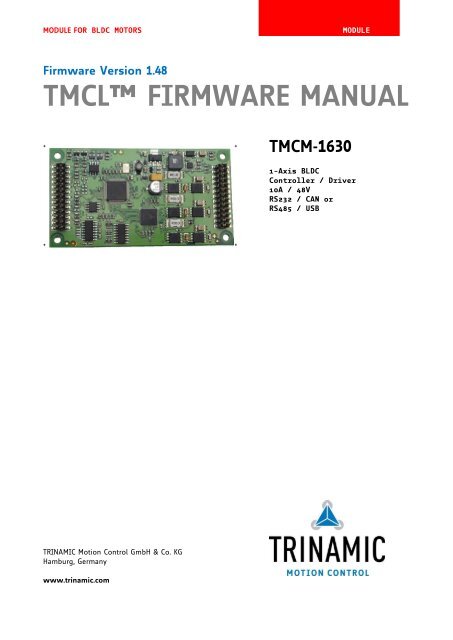
MODULE FOR BLDC MOTORS MODULE<br />
Firmware Version 1.48<br />
TMCL <strong>FIRMWARE</strong> <strong>MANUAL</strong><br />
+ + TMCM-1630<br />
+ +<br />
TRINAMIC Motion Control GmbH & Co. KG<br />
Hamburg, Germany<br />
www.trinamic.com<br />
1-Axis BLDC<br />
Controller / Driver<br />
10A / 48V<br />
RS232 / CAN or<br />
RS485 / USB
TMCM-1630 TMCL Firmware V1.48 Manual (Rev. 1.15 / 2013-JAN-03) 2<br />
Table of Contents<br />
1 Features ........................................................................................................................................................................... 4<br />
2 Overview ......................................................................................................................................................................... 5<br />
3 Putting the TMCM-1630 into Operation .................................................................................................................. 6<br />
3.1 Starting up ............................................................................................................................................................. 6<br />
3.2 Operating the Module in Direct Mode ........................................................................................................... 8<br />
4 TMCL and TMCL-IDE .................................................................................................................................................... 10<br />
4.1 Binary Command Format ................................................................................................................................ 10<br />
4.2 Reply Format ....................................................................................................................................................... 11<br />
4.2.1 Status Codes ................................................................................................................................................. 11<br />
4.3 Standalone Applications .................................................................................................................................. 12<br />
4.4 Testing with a Simple TMCL Program ......................................................................................................... 12<br />
4.5 TMCL Command Overview .............................................................................................................................. 12<br />
4.5.1 TMCL Commands ......................................................................................................................................... 12<br />
4.5.2 Commands Listed According to Subject Area ..................................................................................... 13<br />
4.6 Commands ........................................................................................................................................................... 15<br />
4.6.1 ROR (rotate right)......................................................................................................................................... 15<br />
4.6.2 ROL (rotate left) ............................................................................................................................................ 16<br />
4.6.3 MST (motor stop) ......................................................................................................................................... 17<br />
4.6.4 MVP (move to position) ............................................................................................................................. 18<br />
4.6.5 SAP (set axis parameter) ........................................................................................................................... 19<br />
4.6.6 GAP (get axis parameter) ........................................................................................................................... 20<br />
4.6.7 STAP (store axis parameter) ..................................................................................................................... 21<br />
4.6.8 RSAP (restore axis parameter) ................................................................................................................. 22<br />
4.6.9 SGP (set global parameter) ....................................................................................................................... 23<br />
4.6.10 GGP (get global parameter) ...................................................................................................................... 24<br />
4.6.11 STGP (store global parameter) ................................................................................................................. 24<br />
4.6.12 RSGP (restore global parameter) ............................................................................................................. 25<br />
4.6.13 SIO (set output) ........................................................................................................................................... 26<br />
4.6.14 GIO (get input/output) .............................................................................................................................. 28<br />
4.6.15 CALC (calculate) ............................................................................................................................................ 30<br />
4.6.16 COMP (compare) ........................................................................................................................................... 31<br />
4.6.17 JC (jump conditional).................................................................................................................................. 32<br />
4.6.18 JA (jump always).......................................................................................................................................... 33<br />
4.6.19 CSUB (call subroutine) ................................................................................................................................ 34<br />
4.6.20 RSUB (return from subroutine) ................................................................................................................ 35<br />
4.6.21 WAIT (wait for an event to occur) ......................................................................................................... 36<br />
4.6.22 STOP (stop TMCL program execution) ................................................................................................... 37<br />
4.6.23 CALCX (calculate using the X register) .................................................................................................. 37<br />
4.6.24 AAP (accumulator to axis parameter) .................................................................................................... 38<br />
4.6.25 AGP (accumulator to global parameter) ............................................................................................... 39<br />
4.6.26 Customer Specific TMCL Command Extension (UF0… UF7/User Function)................................... 39<br />
4.6.27 TMCL Control Functions ............................................................................................................................. 40<br />
5 Axis Parameter Overview (SAP, GAP, STAP, RSAP, AAP) ................................................................................. 41<br />
5.1 Axis Parameter Sorted by Functionality ...................................................................................................... 47<br />
6 Global Parameter Overview (SGP, GGP, STGP, RSGP) ....................................................................................... 54<br />
6.1 Bank 0 ................................................................................................................................................................... 54<br />
6.2 Bank 1 ................................................................................................................................................................... 55<br />
6.3 Bank 2 ................................................................................................................................................................... 55<br />
7 PID Regulation ............................................................................................................................................................ 56<br />
7.1 Structure of the Cascaded Motor Regulation Modes............................................................................... 56<br />
7.2 PWM Regulation ................................................................................................................................................. 56<br />
7.3 Current PID Regulation .................................................................................................................................... 56<br />
7.4 Velocity PID Regulation ................................................................................................................................... 58<br />
7.5 Velocity Ramp Generator ................................................................................................................................. 59<br />
7.6 Position PID Regulation ................................................................................................................................... 59<br />
7.7 Parameter Sets for PID Regulation .............................................................................................................. 61<br />
www.trinamic.com
TMCM-1630 TMCL Firmware V1.48 Manual (Rev. 1.15 / 2013-JAN-03) 3<br />
8 Temperature Calculation........................................................................................................................................... 62<br />
9 I²t Monitoring .............................................................................................................................................................. 62<br />
10 Life Support Policy ..................................................................................................................................................... 63<br />
11 Revision History .......................................................................................................................................................... 64<br />
11.1 Firmware Revision ............................................................................................................................................. 64<br />
11.2 Document Revision ........................................................................................................................................... 64<br />
12 References..................................................................................................................................................................... 64<br />
www.trinamic.com
TMCM-1630 TMCL Firmware V1.48 Manual (Rev. 1.15 / 2013-JAN-03) 4<br />
1 Features<br />
The TMCM-1630 is a highly integrated single axis BLDC servo controller module with several interfaceoptions.<br />
The highly integrated module (size: 50mm x 92.5 mm) has been designed in order to be plugged<br />
onto a baseboard. It integrates velocity and position control and offers hall sensor and incremental encoder<br />
(a/b/n) inputs. The module can be used in standalone operation or remote controlled.<br />
Applications<br />
Demanding single and multi-axis BLDC motor solutions<br />
Electrical data<br />
Supply voltage: +24V DC or +48V DC nominal (+12… +55V DC max.)<br />
Motor current: up to 10A RMS (programmable) peak<br />
Integrated motion controller<br />
High performance ARM Cortex-M3 microcontroller for system control and communication protocol<br />
handling<br />
Integrated motor driver<br />
High performance integrated pre-driver (TMC603A)<br />
Support for sensorless back EMF commutation (hallFX)<br />
High-efficient operation, low power dissipation (MOSFETs with low R DS(ON))<br />
Dynamic current control<br />
Integrated protection<br />
On the fly alteration of motion parameters (e.g. position, velocity, acceleration)<br />
Interfaces<br />
Two standard assembly options:<br />
RS232 and CAN (2.0B up to 1Mbit/s)<br />
RS485 and USB<br />
2 analogue and 2 digital inputs<br />
3 open drain outputs<br />
Motor type<br />
Block commutated 3 phase BLDC motors with optional hall sensors / optional encoder<br />
Motor power from a few Watts to nearly 500W<br />
Motor velocity up to 100,000 RPM (electrical field)<br />
Common supply voltages of 12V DC, 24V DC, 36V DC and 48V DC supported<br />
Coil current up to 10A peak<br />
Software<br />
TMCL standalone operation or remote controlled operation<br />
TMCL program memory (non volatile) for up to 2048 TMCL commands<br />
TMCL PC-based application development software TMCL-IDE and TMCL-BLDC available for free<br />
CANopen ready: CiA 301 + CiA 402 (homing mode, profile position mode and velocity mode) under<br />
development<br />
Other<br />
Two double-row 2.54mm connectors<br />
ROHS compliant<br />
Size: 50x92.5mm²<br />
Please see separate TMCM-1630 Hardware Manual for additional information<br />
www.trinamic.com
TMCM-1630 TMCL Firmware V1.48 Manual (Rev. 1.15 / 2013-JAN-03) 5<br />
2 Overview<br />
The software running on the microprocessor of the TMCM-1630 consists of two parts, a boot loader and the<br />
firmware itself. Whereas the boot loader is installed during production and testing at TRINAMIC and remains<br />
untouched throughout the whole lifetime, the firmware can be updated by the user. New versions can be<br />
downloaded free of charge from the TRINAMIC website (http://www.trinamic.com).<br />
The firmware is related to the standard TMCL firmware [TMCL] with regard to protocol and commands. The<br />
module is based on the ARM Cortex-M3 microcontroller and the high performance pre-driver TMC603 and<br />
supports the standard TMCL with a special range of values.<br />
www.trinamic.com
TMCM-1630 TMCL Firmware V1.48 Manual (Rev. 1.15 / 2013-JAN-03) 6<br />
3 Putting the TMCM-1630 into Operation<br />
Here you can find basic information for putting your module into operation. The text contains a simple<br />
example for a TMCL program and a short description of operating the module in direct mode.<br />
THINGS YOU NEED:<br />
TMCM-1630<br />
Interface suitable to your TMCM-1630 with cables<br />
Nominal supply voltage +24V DC or +48V DC for your module<br />
Encoder optional<br />
BLDC motor<br />
TMCL-IDE program and PC<br />
PRECAUTIONS<br />
- Do not mix up connections or short-circuit pins.<br />
- Avoid bounding I/O wires with motor power wires as this may cause noise picked up from the motor supply.<br />
- The power supply has to be buffered by a capacitor. Otherwise the module will be damaged!<br />
- Do not exceed the maximum power supply of 55V DC.<br />
- Do not connect or disconnect the motor while powered!<br />
- Start with power supply OFF!<br />
3.1 Starting up<br />
The following figure shows how the connectors have to be used.<br />
1<br />
3<br />
5<br />
7<br />
9<br />
11<br />
13<br />
15<br />
17<br />
19<br />
21<br />
23<br />
25<br />
+5V<br />
Torque<br />
Dir_IN<br />
Stop_IN<br />
LED_Curlim<br />
GND<br />
Enc_A+<br />
Enc_B+<br />
Enc_N+<br />
CANL/USBD-<br />
CANH/USBD+<br />
USB_+VB<br />
GND<br />
www.trinamic.com<br />
2<br />
4<br />
6<br />
8<br />
10<br />
12<br />
14<br />
16<br />
18<br />
20<br />
22<br />
24<br />
26<br />
Velocity<br />
GND<br />
Tacho<br />
LED_Temp<br />
+5V<br />
GND<br />
Enc_A-<br />
Enc_B-<br />
Enc_N-<br />
RXD/485-<br />
TXD/485+<br />
n.c.<br />
GND<br />
Figure 3.1: Connectors of the TMCM-1630<br />
Domain Connector type Mating connector type<br />
I/Os, interfaces, TSM-113-03-L-DV-K-A, 2x13 poles, double SSW, SSQ, SSM, BSW, ESW, ESQ, BCS, SLW,<br />
encoder row, 2.54mm pitch, SMD vertical, Samtec CES, HLE , IDSS and IDSD series, Samtec<br />
Power, hallFX, TSM-113-03-L-DV-K-A, 2x13 poles, double SSW, SSQ, SSM, BSW, ESW, ESQ, BCS, SLW,<br />
motor<br />
row, 2.54mm pitch, SMD vertical, Samtec CES, HLE , IDSS and IDSD series, Samtec<br />
26<br />
24<br />
22<br />
20<br />
18<br />
16<br />
14<br />
12<br />
10<br />
8<br />
6<br />
4<br />
2<br />
Hall2<br />
Hall3<br />
GND<br />
GND<br />
GND<br />
+VM<br />
+VM<br />
U<br />
U<br />
V<br />
V<br />
W<br />
W<br />
25<br />
23<br />
21<br />
19<br />
17<br />
15<br />
13<br />
11<br />
9<br />
7<br />
5<br />
3<br />
1<br />
Hall1<br />
+5V<br />
GND<br />
GND<br />
GND<br />
+VM<br />
+VM<br />
U<br />
U<br />
V<br />
V<br />
W<br />
W
TMCM-1630 TMCL Firmware V1.48 Manual (Rev. 1.15 / 2013-JAN-03) 7<br />
1. Connect the motor, power supply and hall sensors<br />
Since the two connectors of the TMCM-1630 are similar be careful not to connect the module turned<br />
around. 1. Connect When powered the motor up this and would the power damage supply the as module. follows: Be sure to place the connectors exactly to<br />
their opponents. A deviation of only one pin row can damage the module also.<br />
Start with power supply OFF!<br />
Pin Label Description Pin Label Description<br />
1 W Motor coil W 2 W Motor coil W<br />
3 W Motor coil W 4 W Motor coil W<br />
5 V Motor coil V 6 V Motor coil V<br />
7 V Motor coil V 8 V Motor coil V<br />
9 U Motor coil U 10 U Motor coil U<br />
11 U Motor coil U 12 U Motor coil U<br />
13 VM Module driver supply voltage 14 VM Module driver supply voltage<br />
15 VM Module driver supply voltage 16 VM Module driver supply voltage<br />
17 GND<br />
Module ground (power supply and<br />
signal ground)<br />
18 GND<br />
Module ground (power supply<br />
and signal ground)<br />
19 GND<br />
Module ground (power supply and<br />
signal ground)<br />
20 GND<br />
Module ground (power supply<br />
and signal ground)<br />
21 GND<br />
Module ground (power supply and<br />
signal ground)<br />
22 GND<br />
Module ground (power supply<br />
and signal ground)<br />
23 +5V<br />
+5V output (100mA max.) for<br />
encoder and/or hall sensor supply<br />
24 HALL3 Hall sensor 3 signal input<br />
25 HALL1 Hall sensor 1 signal input 26 HALL2 Hall sensor 2 signal input<br />
2. Connect the interface, IOs and the encoder as follows:<br />
Since the two connectors of the TMCM-1630 are similar be careful not to connect the module turned<br />
around. When powered up this would damage the module. Be sure to place the connectors exactly to<br />
their opponents. A deviation of only one pin row can damage the module also.<br />
Pin Label Description Pin Label Description<br />
1 +5V<br />
3 Torque<br />
5 Dir_IN<br />
7 Stop_IN<br />
9 LED-Curlim<br />
www.trinamic.com<br />
5V analog reference as used by the<br />
internal DAC.<br />
Max. load 0.5mA<br />
Used for max. motor current /<br />
torque control in standalone<br />
operation by supplying external 0-<br />
10V signal<br />
5V TTL input. Tie to GND to inverse<br />
motor direction, leave open or tie<br />
to 5V otherwise.<br />
Emergency stop. Tie this pin to<br />
GND to stop the motor (same as<br />
the Motor OFF switch on PCB). The<br />
motor can be restarted via the<br />
interface, or by cycling the power<br />
supply<br />
High, when module goes into<br />
current limiting mode<br />
2 Velocity<br />
4 GND<br />
6 Tacho<br />
8 LED-Temp<br />
10 +5V<br />
Used for velocity control in<br />
standalone operation by<br />
supplying external 0 - 10V<br />
signal<br />
Module ground (power supply<br />
and signal ground)<br />
This pin outputs a tacho<br />
impulse, i.e. toggles on each<br />
hall sensor change<br />
5V TTL output: Toggling with<br />
3Hz when temperature prewarning<br />
threshold is exceeded,<br />
high when module shut down<br />
due to overtemperature<br />
5V output as reference for<br />
external purpose<br />
11 GND GND reference 12 GND GND reference<br />
13 Enc_A+ Encoder A+ channel 14 Enc_A- Encoder A- channel
TMCM-1630 TMCL Firmware V1.48 Manual (Rev. 1.15 / 2013-JAN-03) 8<br />
15 Enc_B+ Encoder B+ channel 16 Enc_B- Encoder B- channel<br />
17 Enc_N+ Encoder N+ channel 18 Enc_N- Encoder N- channel<br />
19<br />
CAN low /<br />
CANL/USBD-<br />
USB D- bus line<br />
20 RXD/<br />
485-<br />
RXD signal for RS232 /<br />
inverting signal for RS485<br />
21<br />
CAN high /<br />
CANH/USBD+<br />
USB D+ bus line<br />
22 TXD/<br />
485+<br />
TXD signal for RS232 /<br />
non inverting signal for RS485<br />
23 USB_+VB<br />
Use to detect availability of<br />
attached host system (e.g. PC)<br />
24 n.c.<br />
25 GND GND reference 26 GND GND reference<br />
3. Switch ON the power supply<br />
The power LED is ON now.<br />
If this does not occur, switch power OFF and check your connections as well as the power<br />
supply.<br />
4. Start the TMCL-IDE software development environment<br />
The TMCL-IDE is available on the TechLibCD and on www.trinamic.com.<br />
Installing the TMCL-IDE<br />
Make sure the COM port you intend to use is not blocked by another program.<br />
Open TMCL-IDE by clicking TMCL.exe.<br />
Choose Setup and Options and thereafter the Connection tab. Choose Type. The TMCL-IDE shows<br />
you which Port the module uses. Click OK.<br />
Figure 3.2: Setup menu Figure 3.3: Connection tab of TMCL-IDE<br />
3.2 Operating the Module in Direct Mode<br />
1. Start TMCL Direct Mode.<br />
www.trinamic.com<br />
Direct Mode<br />
2. If the communication is established the TMCM-1630 is automatically detected. If the module is not<br />
detected, please check all points above (cables, interface, power supply, COM port, baud rate).<br />
3. Issue a command by choosing instruction, type (if necessary), motor, and value and click execute<br />
to send it to the module.
TMCM-1630 TMCL Firmware V1.48 Manual (Rev. 1.15 / 2013-JAN-03) 9<br />
Figure 3.4: TMCL direct mode window<br />
Examples:<br />
ROR rotate right, motor 0, value 500 -> Click Execute. The first motor is rotating now.<br />
MST motor stop, motor 0 -> Click Execute. The first motor stops now.<br />
www.trinamic.com
TMCM-1630 TMCL Firmware V1.48 Manual (Rev. 1.15 / 2013-JAN-03) 10<br />
4 TMCL and TMCL-IDE<br />
The TMCM-1630 module supports TMCL direct mode (binary commands) and standalone TMCL program<br />
execution. You can store up to 2048 TMCL instructions on it.<br />
In direct mode the TMCL communication over USB, CAN, RS232, and RS485 follows a strict master/slave<br />
relationship. That is, a host computer (e.g. PC/PLC) acting as the interface bus master will send a command<br />
to the module. The TMCL interpreter on it will then interpret this command, do the initialization of the<br />
motion controller, read inputs and write outputs or whatever is necessary according to the specified<br />
command. As soon as this step has been done, the module will send a reply back over the interface to the<br />
bus master. The master should not transfer the next command till then. Normally, the module will just<br />
switch to transmission and occupy the bus for a reply, otherwise it will stay in receive mode. It will not<br />
send any data over the interface without receiving a command first. This way, any collision on the bus will<br />
be avoided when there are more than two nodes connected to a single bus.<br />
The <strong>Trinamic</strong> Motion Control Language (TMCL) provides a set of structured motion control commands. Every<br />
motion control command can be given by a host computer or can be stored on the TMCM-1630 to form<br />
programs that run standalone on the module. For this purpose there are not only motion control commands<br />
but also commands to control the program structure (like conditional jumps, compare and calculating).<br />
Every command has a binary representation and a mnemonic:<br />
- The binary format is used to send commands from the host to a module in direct mode.<br />
- The mnemonic format is used for easy usage of the commands when developing standalone TMCL<br />
applications with the TMCL-IDE (IDE means Integrated Development Environment).<br />
There is also a set of configuration variables for the axis and for global parameters which allow individual<br />
configuration of nearly every function of a module. This manual gives a detailed description of all TMCL<br />
commands and their usage.<br />
4.1 Binary Command Format<br />
When commands are sent from a host to a module, the binary format has to be used. Every command<br />
consists of a one-byte command field, a one-byte type field, a one-byte motor/bank field and a four-byte<br />
value field. So the binary representation of a command always has seven bytes.<br />
When a command is to be sent via RS232, USB or RS485 interface, it has to be enclosed by an address byte<br />
at the beginning and a checksum byte at the end. In this case it consists of nine bytes.<br />
The binary command format for RS232/RS485/USB is structured as follows:<br />
Bytes Meaning<br />
1 Module address<br />
1 Command number<br />
1 Type number<br />
1 Motor or Bank number<br />
4 Value (MSB first!)<br />
1 Checksum<br />
When using CAN bus, the first byte (reply address) and the last byte (checksum) are left out.<br />
Do not send the next command before you have received the reply!<br />
www.trinamic.com
TMCM-1630 TMCL Firmware V1.48 Manual (Rev. 1.15 / 2013-JAN-03) 11<br />
Checksum calculation<br />
As mentioned above, the checksum is calculated by adding up all bytes (including the module address byte)<br />
using 8-bit addition. Here is an example for the calculation:<br />
in C:<br />
unsigned char i, Checksum;<br />
unsigned char Command[9];<br />
//Set the “Command” array to the desired command<br />
Checksum = Command[0];<br />
for(i=1; i
TMCM-1630 TMCL Firmware V1.48 Manual (Rev. 1.15 / 2013-JAN-03) 12<br />
4.3 Standalone Applications<br />
The module is equipped with an EEPROM for storing TMCL applications. You can use the TMCL-IDE for<br />
developing standalone TMCL applications. You can load your program down into the EEPROM and then it<br />
will run on the module. The TMCL-IDE contains an editor and a TMCL assembler where the commands can<br />
be entered using their mnemonic format. They will be assembled automatically into their binary<br />
representations. Afterwards this code can be downloaded into the module to be executed there.<br />
4.4 Testing with a Simple TMCL Program<br />
Open the file test2.tmc of the TMCL-IDE. The following source code appears on the screen:<br />
//A simple example for using TMCL and TMCL-IDE<br />
www.trinamic.com<br />
Loop:<br />
ROL 0, 4000 //rotate left with 4000 rev/min<br />
WAIT TICKS, 0, 2000<br />
ROR 0, 4000 //rotate right with 4000 rev/min<br />
WAIT TICKS, 0, 2000<br />
JA Loop<br />
Assemble<br />
Download Run<br />
Stop<br />
Figure 4.1: Assemble, download, stop, and run icons of TMCL-IDE<br />
1. Click on icon Assemble to convert the example into binary code.<br />
2. Then download the program to the TMCM-1630 module via the icon Download.<br />
3. Press icon Run. The desired program will be executed.<br />
4. Click Stop button to stop the program.<br />
For further information about the TMCL-IDE and TMCL programming techniques please refer to the TMCL-IDE<br />
User Manual on TRINAMICs website.<br />
TRINAMIC offers two software tools for BLDC applications: the TMCL-BLDC and the BLDC tool of the<br />
TMCL-IDE. Whereas the TMCL-BLDC is used for testing different configurations in all modes of<br />
operation the TMCL-IDE is mainly designed for conceiving programs and firmware updates. New<br />
versions of the TMCL-BLDC and the TMCL-IDE can be downloaded free of charge from the TRINAMIC<br />
website (http://www.trinamic.com).<br />
4.5 TMCL Command Overview<br />
The following section provides a short overview of the TMCL commands supported by the TMCM-1630.<br />
4.5.1 TMCL Commands<br />
Command Number Parameter Description<br />
ROR 1 , Rotate right with specified velocity<br />
ROL 2 , Rotate left with specified velocity<br />
MST 3 Motor stop movement<br />
MVP 4 ABS|REL, , Move to position (absolute or<br />
relative)<br />
SAP 5 , , Set axis parameter (motion control<br />
specific settings)<br />
GAP 6 , Get axis parameter (read out<br />
motion control specific settings)
TMCM-1630 TMCL Firmware V1.48 Manual (Rev. 1.15 / 2013-JAN-03) 13<br />
Command Number Parameter Description<br />
STAP 7 , Store axis parameter permanently<br />
(non volatile)<br />
RSAP 8 , Restore axis parameter<br />
SGP 9 , , Set global parameter (module<br />
specific, e.g. communication<br />
settings or TMCL user variables)<br />
GGP 10 , Get global parameter (module<br />
specific, e.g. communication<br />
settings or TMCL user variables)<br />
STGP 11 , Store global parameter (TMCL user<br />
variables only)<br />
RSGP 12 , Restore global parameter (TMCL<br />
user variables only)<br />
SIO 14 , , Set output<br />
GIO 15 , Get input<br />
CALC 19 , Process accumulator & value<br />
COMP 20 Compare accumulator value<br />
JC 21 , Jump conditional<br />
JA 22 Jump absolute<br />
CSUB 23 Call subroutine<br />
RSUB 24 Return from subroutine<br />
WAIT 27 , , Wait with further program<br />
execution<br />
STOP 28 Stop program execution<br />
CALCX 33 Process accumulator & X-register<br />
AAP 34 , Accumulator to axis parameter<br />
AGP 35 , Accumulator to global parameter<br />
4.5.2 Commands Listed According to Subject Area<br />
4.5.2.1 Motion Commands<br />
These commands control the motion of the motor. They are the most important commands and can be used<br />
in direct mode or in standalone mode.<br />
Mnemonic Command number Meaning<br />
ROL 2 Rotate left<br />
ROR 1 Rotate right<br />
MVP 4 Move to position<br />
MST 3 Motor stop<br />
4.5.2.2 Parameter Commands<br />
These commands are used to set, read and store axis parameters or global parameters. Axis parameters can<br />
be set independently for the axis, whereas global parameters control the behavior of the module itself.<br />
These commands can also be used in direct mode and in standalone mode.<br />
Mnemonic Command number Meaning<br />
SAP 5 Set axis parameter<br />
GAP 6 Get axis parameter<br />
STAP 7 Store axis parameter into EEPROM<br />
RSAP 8 Restore axis parameter from EEPROM<br />
SGP 9 Set global parameter<br />
GGP 10 Get global parameter<br />
STGP 11 Store global parameter into EEPROM<br />
RSGP 12 Restore global parameter from EEPROM<br />
www.trinamic.com
TMCM-1630 TMCL Firmware V1.48 Manual (Rev. 1.15 / 2013-JAN-03) 14<br />
4.5.2.3 Control Commands<br />
These commands are used to control the program flow (loops, conditions, jumps etc.). It does not make<br />
sense to use them in direct mode. They are intended for standalone mode only.<br />
Mnemonic Command number Meaning<br />
JA 22 Jump always<br />
JC 21 Jump conditional<br />
COMP 20 Compare accumulator with constant<br />
value<br />
CSUB 23 Call subroutine<br />
RSUB 24 Return from subroutine<br />
WAIT 27 Wait for a specified event<br />
STOP 28 End of a TMCL program<br />
4.5.2.4 I/O Port Commands<br />
These commands control the external I/O ports and can be used in direct mode and in standalone mode.<br />
Mnemonic Command number Meaning<br />
SIO 14 Set output<br />
GIO 15 Get input<br />
4.5.2.5 Calculation Commands<br />
These commands are intended to be used for calculations within TMCL applications in standalone mode,<br />
only. For calculating purposes there are an accumulator (or accu or A register) and an X register. When<br />
executed in a TMCL program (in standalone mode), all TMCL commands that read a value store the result in<br />
the accumulator. The X register can be used as an additional memory when doing calculations. It can be<br />
loaded from the accumulator.<br />
Mnemonic Command number Meaning<br />
CALC 19 Calculate using the accumulator and a<br />
constant value<br />
CALCX 33 Calculate using the accumulator and the<br />
X register<br />
AAP 34 Copy accumulator to an axis parameter<br />
AGP 35 Copy accumulator to a global parameter<br />
Mixing standalone program execution and direct mode<br />
It is possible to use some commands in direct mode while a standalone program is active. When a<br />
command which reads out a value is executed (direct mode) the accumulator will not be affected. While a<br />
TMCL program is running standalone on the module, a host can still send commands like GAP and GGP to it<br />
(e.g. to query the actual position of the motor) without affecting the flow of the TMCL program running<br />
standalone on the module.<br />
www.trinamic.com
TMCM-1630 TMCL Firmware V1.48 Manual (Rev. 1.15 / 2013-JAN-03) 15<br />
4.6 Commands<br />
The module specific commands are explained in more detail on the following pages. They are listed<br />
according to their command number.<br />
4.6.1 ROR (rotate right)<br />
The motor will be instructed to rotate with a specified velocity in right direction (increasing the position<br />
counter).<br />
Internal function: First, velocity mode is selected. Then, the velocity value is transferred to axis parameter<br />
#2 (target velocity).<br />
Related commands: ROL, MST, SAP, GAP<br />
Mnemonic: ROR 0, <br />
Binary representation:<br />
COMMAND TYPE MOT/BANK VALUE <br />
www.trinamic.com<br />
1 don’t care 0 -2147483648… +2147483647<br />
Reply in direct mode:<br />
STATUS COMMAND VALUE<br />
Example:<br />
Rotate right, velocity = 350<br />
Mnemonic: ROR 0, 350<br />
100 – OK 1 don’t care<br />
Binary:<br />
Byte Index 0 1 2 3 4 5 6 7<br />
Function Target- Instruction Type Motor/ Operand Operand Operand Operand<br />
address Number<br />
Bank Byte3 Byte2 Byte1 Byte0<br />
Value (hex) $01 $01 $00 $00 $00 $00 $01 $5e
TMCM-1630 TMCL Firmware V1.48 Manual (Rev. 1.15 / 2013-JAN-03) 16<br />
4.6.2 ROL (rotate left)<br />
The motor will be instructed to rotate with a specified velocity (opposite direction compared to ROR,<br />
decreasing the position counter).<br />
Internal function: First, velocity mode is selected. Then, the velocity value is transferred to axis parameter<br />
#2 (target velocity).<br />
Related commands: ROR, MST, SAP, GAP<br />
Mnemonic: ROL 0, <br />
Binary representation:<br />
COMMAND TYPE MOT/BANK VALUE<br />
www.trinamic.com<br />
2 don’t care 0 <br />
-2147483648… +2147483647<br />
Reply in direct mode:<br />
STATUS COMMAND VALUE<br />
100 – OK 2 don’t care<br />
Example:<br />
Rotate left, velocity = 1200<br />
Mnemonic: ROL 0, 1200<br />
Binary:<br />
Byte Index 0 1 2 3 4 5 6 7<br />
Function Target- Instruction Type Motor/ Operand Operand Operand Operand<br />
address Number<br />
Bank Byte3 Byte2 Byte1 Byte0<br />
Value (hex) $01 $02 $00 $00 $00 $00 $04 $b0
TMCM-1630 TMCL Firmware V1.48 Manual (Rev. 1.15 / 2013-JAN-03) 17<br />
4.6.3 MST (motor stop)<br />
The motor will be instructed to stop.<br />
Internal function: The axis parameter target velocity is set to zero.<br />
Related commands: ROL, ROR, SAP, GAP<br />
Mnemonic: MST 0<br />
Binary representation:<br />
COMMAND TYPE MOT/BANK VALUE<br />
www.trinamic.com<br />
3 don’t care 0 don’t care<br />
Reply in direct mode:<br />
STATUS COMMAND VALUE<br />
Example:<br />
Stop motor<br />
Mnemonic: MST 0<br />
100 – OK 3 don’t care<br />
Binary:<br />
Byte Index 0 1 2 3 4 5 6 7<br />
Function Target- Instruction Type Motor/ Operand Operand Operand Operand<br />
address Number<br />
Bank Byte3 Byte2 Byte1 Byte0<br />
Value (hex) $01 $03 $00 $00 $00 $00 $00 $00
TMCM-1630 TMCL Firmware V1.48 Manual (Rev. 1.15 / 2013-JAN-03) 18<br />
4.6.4 MVP (move to position)<br />
The motor will be instructed to move to a specified relative or absolute position. It uses the<br />
acceleration/deceleration ramp and the positioning speed programmed into the unit. This command is nonblocking<br />
(like all commands). A reply will be sent immediately after command interpretation and<br />
initialization of the motion controller. Further commands may follow without waiting for the motor reaching<br />
its end position. The maximum velocity and acceleration are defined by axis parameters #4 and #11.<br />
Two operation types are available:<br />
Moving to an absolute position in the range from -2147483648… +2147483647.<br />
Starting a relative movement by means of an offset to the actual position. In this case, the new<br />
resulting position value must not exceed the above mentioned limits, too.<br />
Internal function: A new position value is transferred to the axis parameter #0 target position.<br />
Related commands: SAP, GAP, and MST<br />
Mnemonic: MVP , 0, <br />
Binary representation:<br />
COMMAND TYPE MOT/BANK VALUE<br />
4 0 ABS – absolute 0 <br />
-2147483648… +2147483647<br />
1 REL – relative 0 <br />
-2147483648… +2147483647<br />
Reply in direct mode:<br />
STATUS COMMAND VALUE<br />
www.trinamic.com<br />
100 – OK 4 don’t care<br />
Example MVP ABS:<br />
Move motor to (absolute) position 9000<br />
Mnemonic: MVP ABS, 0, 9000<br />
Binary:<br />
Byte Index 0 1 2 3 4 5 6 7<br />
Function Target- Instruction Type Motor/ Operand Operand Operand Operand<br />
address Number<br />
Bank Byte3 Byte2 Byte1 Byte0<br />
Value (hex) $01 $04 $00 $00 $00 $00 $23 $28<br />
Example MVP REL:<br />
Move motor from current position 1000 steps backward (move relative -1000)<br />
Mnemonic: MVP REL, 0, -1000<br />
Binary:<br />
Byte Index 0 1 2 3 4 5 6 7<br />
Function Target- Instruction Type Motor/ Operand Operand Operand Operand<br />
address Number<br />
Bank Byte3 Byte2 Byte1 Byte0<br />
Value (hex) $00 $04 $01 $00 $ff $ff $fc $18
TMCM-1630 TMCL Firmware V1.48 Manual (Rev. 1.15 / 2013-JAN-03) 19<br />
4.6.5 SAP (set axis parameter)<br />
Most of the motion control parameters of the module can be specified by using the SAP command. The<br />
settings will be stored in SRAM and therefore are volatile. Thus, information will be lost after power off.<br />
Please use command STAP (store axis parameter) in order to store any setting permanently.<br />
Related commands: GAP, STAP, and RSAP<br />
Mnemonic: SAP , 0, <br />
Binary representation:<br />
COMMAND TYPE MOT/BANK VALUE<br />
www.trinamic.com<br />
5 0 <br />
Reply in direct mode:<br />
STATUS COMMAND VALUE<br />
100 – OK 5 don’t care<br />
A list of all parameters which can be used for the SAP command is shown in section 5.<br />
Example:<br />
Set the absolute maximum current to 200mA<br />
Mnemonic: SAP 6, 0, 200<br />
Binary:<br />
Byte Index 0 1 2 3 4 5 6 7<br />
Function Target- Instruction Type Motor/ Operand Operand Operand Operand<br />
address Number<br />
Bank Byte3 Byte2 Byte1 Byte0<br />
Value (hex) $01 $05 $00 $00 $00 $00 $00 $c8
TMCM-1630 TMCL Firmware V1.48 Manual (Rev. 1.15 / 2013-JAN-03) 20<br />
4.6.6 GAP (get axis parameter)<br />
Most parameters of the TMCM-1630 can be adjusted individually. They can be read out using the GAP<br />
command.<br />
Related commands: SAP, STAP, and RSAP<br />
Mnemonic: GAP , 0<br />
Binary representation:<br />
COMMAND TYPE MOT/BANK VALUE<br />
www.trinamic.com<br />
6 0 don’t care<br />
Reply in direct mode:<br />
STATUS COMMAND VALUE<br />
100 – OK 6 don’t care<br />
A list of all parameters which can be used for the GAP command is shown in section 5.<br />
Example:<br />
Get the actual position of motor<br />
Mnemonic: GAP 1, 0<br />
Binary:<br />
Byte Index 0 1 2 3 4 5 6 7<br />
Function Target- Instruction Type Motor/ Operand Operand Operand Operand<br />
address Number<br />
Bank Byte3 Byte2 Byte1 Byte0<br />
Value (hex) $01 $06 $01 $00 $00 $00 $00 $00<br />
Reply:<br />
Byte Index 0 1 2 3 4 5 6 7<br />
Function Host- Target- Status Instruction Operand Operand Operand Operand<br />
address address<br />
Byte3 Byte2 Byte1 Byte0<br />
Value (hex) $00 $00 $64 $06 $00 $00 $02 $c7
TMCM-1630 TMCL Firmware V1.48 Manual (Rev. 1.15 / 2013-JAN-03) 21<br />
4.6.7 STAP (store axis parameter)<br />
The STAP command stores an axis parameter previously set with a Set Axis Parameter command (SAP)<br />
permanently. Most parameters are automatically restored after power up (refer to axis parameter list in<br />
chapter 5).<br />
Internal function: An axis parameter value stored in SRAM will be transferred to EEPROM and loaded from<br />
EEPORM after next power up.<br />
Related commands: SAP, RSAP, and GAP<br />
Mnemonic: STAP , 0<br />
Binary representation:<br />
COMMAND TYPE MOT/BANK VALUE<br />
www.trinamic.com<br />
7 0 don’t care*<br />
* The value operand of this function has no effect. Instead, the currently used value (e.g. selected by SAP) is saved.<br />
Reply in direct mode:<br />
STATUS COMMAND VALUE<br />
100 – OK 7 don’t care<br />
A list of all parameters which can be used for the STAP command is shown in section 5.<br />
Example:<br />
Store the maximum speed<br />
Mnemonic: STAP 4, 0<br />
Binary:<br />
Byte Index 0 1 2 3 4 5 6 7<br />
Function Target- Instruction Type Motor/ Operand Operand Operand Operand<br />
address Number<br />
Bank Byte3 Byte2 Byte1 Byte0<br />
Value (hex) $01 $07 $04 $00 $00 $00 $00 $00<br />
Note: The STAP command will not have any effect when the configuration EEPROM is locked. The error<br />
code 5 (configuration EEPROM locked) will be returned in this case.
TMCM-1630 TMCL Firmware V1.48 Manual (Rev. 1.15 / 2013-JAN-03) 22<br />
4.6.8 RSAP (restore axis parameter)<br />
For all configuration related axis parameters non-volatile memory locations are provided. By default, most<br />
parameters are automatically restored after power up (refer to axis parameter list in chapter 5). A single<br />
parameter that has been changed before can be reset by this instruction also.<br />
Internal function: The specified parameter is copied from the configuration EEPROM memory to its RAM<br />
location.<br />
Related commands: SAP, STAP, and GAP<br />
Mnemonic: RSAP , 0<br />
Binary representation:<br />
COMMAND TYPE MOT/BANK VALUE<br />
www.trinamic.com<br />
8 0 don’t care<br />
Reply in direct mode:<br />
STATUS COMMAND VALUE<br />
100 – OK 8 don’t care<br />
A list of all parameters which can be used for the RSAP command is shown in section 5.<br />
Example:<br />
Restore the maximum current<br />
Mnemonic: RSAP 6, 0<br />
Binary:<br />
Byte Index 0 1 2 3 4 5 6 7<br />
Function Target- Instruction Type Motor/ Operand Operand Operand Operand<br />
address Number<br />
Bank Byte3 Byte2 Byte1 Byte0<br />
Value (hex) $01 $08 $06 $00 $00 $00 $00 $00
TMCM-1630 TMCL Firmware V1.48 Manual (Rev. 1.15 / 2013-JAN-03) 23<br />
4.6.9 SGP (set global parameter)<br />
Global parameters are related to the host interface, peripherals or other application specific variables. The<br />
different groups of these parameters are organized in banks to allow a larger total number for future<br />
products. Currently, only bank 0 and 1 are used for global parameters, and only bank 2 is intended to use<br />
for user variables.<br />
Related commands: GGP, STGP, RSGP<br />
Mnemonic: SGP , , <br />
Binary representation:<br />
COMMAND TYPE MOT/BANK VALUE<br />
www.trinamic.com<br />
9 <br />
Reply in direct mode:<br />
STATUS VALUE<br />
100 – OK don’t care<br />
A list of all parameters which can be used for the SGP command is shown in section 6.<br />
Example: set variable 0 at bank 2 to 100<br />
Mnemonic: SGP, 0, 2, 100<br />
Binary:<br />
Byte Index 0 1 2 3 4 5 6 7<br />
Function Target- Instruction Type Motor/ Operand Operand Operand Operand<br />
address Number<br />
Bank Byte3 Byte2 Byte1 Byte0<br />
Value (hex) $01 $09 $00 $02 $00 $00 $00 $64
TMCM-1630 TMCL Firmware V1.48 Manual (Rev. 1.15 / 2013-JAN-03) 24<br />
4.6.10 GGP (get global parameter)<br />
All global parameters can be read with this function.<br />
Related commands: SGP, STGP, RSGP<br />
Mnemonic: GGP , <br />
Binary representation:<br />
COMMAND TYPE MOT/BANK VALUE<br />
www.trinamic.com<br />
10 don’t care<br />
Reply in direct mode:<br />
STATUS VALUE<br />
100 – OK <br />
A list of all parameters which can be used for the GGP command is shown in section 6.<br />
Example: get variable 0 from bank 2<br />
Mnemonic: GGP, 0, 2<br />
Binary:<br />
Byte Index 0 1 2 3 4 5 6 7<br />
Function Target- Instruction Type Motor/ Operand Operand Operand Operand<br />
address Number<br />
Bank Byte3 Byte2 Byte1 Byte0<br />
Value (hex) $01 $0a $00 $02 $00 $00 $00 $00<br />
4.6.11 STGP (store global parameter)<br />
Some global parameters are located in RAM memory, so modifications are lost at power down. This<br />
instruction copies a value from its RAM location to the configuration EEPROM and enables permanent<br />
storing. Most parameters are automatically restored after power up.<br />
Related commands: SGP, GGP, RSGP<br />
Mnemonic: STGP , <br />
Binary representation:<br />
COMMAND TYPE MOT/BANK VALUE<br />
11 don’t care<br />
Reply in direct mode:<br />
STATUS VALUE<br />
100 – OK don’t care<br />
A list of all parameters which can be used for the STGP command is shown in section 6.<br />
Example: copy variable 0 at bank 2 to the configuration EEPROM<br />
Mnemonic: STGP, 0, 2<br />
Binary:<br />
Byte Index 0 1 2 3 4 5 6 7<br />
Function Target- Instruction Type Motor/ Operand Operand Operand Operand<br />
address Number<br />
Bank Byte3 Byte2 Byte1 Byte0<br />
Value (hex) $01 $0b $00 $02 $00 $00 $00 $00
TMCM-1630 TMCL Firmware V1.48 Manual (Rev. 1.15 / 2013-JAN-03) 25<br />
4.6.12 RSGP (restore global parameter)<br />
This instruction copies a value from the configuration EEPROM to its RAM location and so recovers the<br />
permanently stored value of a RAM-located parameter. Most parameters are automatically restored after<br />
power up.<br />
Related commands: SGP, GGP, STGP<br />
Mnemonic: RSGP , <br />
Binary representation:<br />
COMMAND TYPE MOT/BANK VALUE<br />
www.trinamic.com<br />
12 don’t care<br />
Reply in direct mode:<br />
STATUS VALUE<br />
100 – OK don’t care<br />
A list of all parameters which can be used for the RSGP command is shown in section 6.<br />
Example: copy variable 0 at bank 2 from the configuration EEPROM to the RAM location<br />
Mnemonic: RSGP, 0, 2<br />
Binary:<br />
Byte Index 0 1 2 3 4 5 6 7<br />
Function Target- Instruction Type Motor/ Operand Operand Operand Operand<br />
address Number<br />
Bank Byte3 Byte2 Byte1 Byte0<br />
Value (hex) $01 $0c $00 $02 $00 $00 $00 $00
TMCM-1630 TMCL Firmware V1.48 Manual (Rev. 1.15 / 2013-JAN-03) 26<br />
4.6.13 SIO (set output)<br />
This command sets the status of the general digital outputs either to low (0) or to high (1).<br />
Internal function: The passed value is transferred to the specified output line.<br />
Related commands: GIO, WAIT<br />
Mnemonic: SIO , , <br />
Binary representation:<br />
INSTRUCTION NO. TYPE MOT/BANK VALUE<br />
www.trinamic.com<br />
14 <br />
Reply structure:<br />
STATUS VALUE<br />
100 – OK (don't care)<br />
Example:<br />
Set OUT_1 to high (bank 2, output 1; general purpose output)<br />
Mnemonic: SIO 0, 2, 1<br />
Binary:<br />
Byte Index 0 1 2 3 4 5 6 7<br />
Function Target- Instruction Type Motor/ Operand Operand Operand Operand<br />
address Number<br />
Bank Byte3 Byte2 Byte1 Byte0<br />
Value (hex) $01 $0e $00 $02 $00 $00 $00 $01<br />
1<br />
3<br />
5<br />
7<br />
9<br />
11<br />
13<br />
15<br />
17<br />
19<br />
21<br />
23<br />
25<br />
+5V<br />
Torque<br />
Dir_IN<br />
Stop_IN<br />
LED_Curlim<br />
GND<br />
Enc_A+<br />
Enc_B+<br />
Enc_N+<br />
CANL/USBD-<br />
CANH/USBD+<br />
USB_+VB<br />
GND<br />
2<br />
4<br />
6<br />
8<br />
10<br />
12<br />
14<br />
16<br />
18<br />
20<br />
22<br />
24<br />
26<br />
Velocity<br />
GND<br />
Tacho<br />
LED_Temp<br />
+5V<br />
GND<br />
Enc_A-<br />
Enc_B-<br />
Enc_N-<br />
RXD/485-<br />
TXD/485+<br />
n.c.<br />
GND<br />
Figure 4.2: Connectors of the TMCM-1630<br />
26<br />
24<br />
22<br />
20<br />
18<br />
16<br />
14<br />
12<br />
10<br />
8<br />
6<br />
4<br />
2<br />
Hall2<br />
Hall3<br />
GND<br />
GND<br />
GND<br />
+VM<br />
+VM<br />
U<br />
U<br />
V<br />
V<br />
W<br />
W<br />
25<br />
23<br />
21<br />
19<br />
17<br />
15<br />
13<br />
11<br />
9<br />
7<br />
5<br />
3<br />
1<br />
Hall1<br />
+5V<br />
GND<br />
GND<br />
GND<br />
+VM<br />
+VM<br />
U<br />
U<br />
V<br />
V<br />
W<br />
W
TMCM-1630 TMCL Firmware V1.48 Manual (Rev. 1.15 / 2013-JAN-03) 27<br />
Available I/O port of TMCM-1630:<br />
Pin I/O port Command Range<br />
6 Tacho SIO 0, 2, 1/0<br />
Example:<br />
Set the output pin high.<br />
Mnemonic: SIO 0, 2, 1<br />
The following program will show the states of the input lines on the output lines:<br />
Loop: GIO 255, 0<br />
SIO 255, 2,-1<br />
JA Loop<br />
Please ask TRINAMIC if you need more general digital outputs. On request, it is possible to change<br />
LED_Temp and LED_Curlimit into general digital outputs.<br />
www.trinamic.com
TMCM-1630 TMCL Firmware V1.48 Manual (Rev. 1.15 / 2013-JAN-03) 28<br />
4.6.14 GIO (get input/output)<br />
With this command the status of the three available general purpose inputs of the module can be read out.<br />
The function reads a digital or analogue input port. Digital lines will read 0 and 1, while the ADC channels<br />
deliver their 10 bit result in the range of 0… 1023. In standalone mode the requested value is copied to the<br />
accumulator (accu) for further processing purposes such as conditioned jumps. In direct mode the value is<br />
only output in the value field of the reply, without affecting the accumulator. The actual status of a digital<br />
output line can also be read.<br />
Internal function: The specified line is read.<br />
Related commands: SIO, WAIT<br />
Mnemonic: GIO , <br />
Binary representation:<br />
INSTRUCTION NO. TYPE MOT/BANK VALUE<br />
www.trinamic.com<br />
15 (don't care)<br />
Reply in direct mode:<br />
STATUS VALUE<br />
100 – OK <br />
Example:<br />
Get the analogue value of ADC channel 0<br />
Mnemonic: GIO 0, 1<br />
Binary:<br />
Byte Index 0 1 2 3 4 5 6 7<br />
Function Target- Instruction Type Motor/ Operand Operand Operand Operand<br />
address Number<br />
Bank Byte3 Byte2 Byte1 Byte0<br />
Value (hex) $01 $0f $00 $01 $00 $00 $00 $00<br />
Reply:<br />
Byte Index 0 1 2 3 4 5 6 7<br />
Function Host- Target- Status Instruction Operand Operand Operand Operand<br />
address address<br />
Byte3 Byte2 Byte1 Byte0<br />
Value (hex) $02 $01 $64 $0f $00 $00 $01 $fa<br />
value: 506
TMCM-1630 TMCL Firmware V1.48 Manual (Rev. 1.15 / 2013-JAN-03) 29<br />
1<br />
3<br />
5<br />
7<br />
9<br />
11<br />
13<br />
15<br />
17<br />
19<br />
21<br />
23<br />
25<br />
+5V<br />
Torque<br />
Dir_IN<br />
Stop_IN<br />
LED_Curlim<br />
GND<br />
Enc_A+<br />
Enc_B+<br />
Enc_N+<br />
CANL/USBD-<br />
CANH/USBD+<br />
USB_+VB<br />
GND<br />
www.trinamic.com<br />
2<br />
4<br />
6<br />
8<br />
10<br />
12<br />
14<br />
16<br />
18<br />
20<br />
22<br />
24<br />
26<br />
Velocity<br />
GND<br />
Tacho<br />
LED_Temp<br />
+5V<br />
GND<br />
Enc_A-<br />
Enc_B-<br />
Enc_N-<br />
RXD/485-<br />
TXD/485+<br />
n.c.<br />
GND<br />
Figure 4.3: Connectors of the TMCM-1630<br />
4.6.14.1 I/O bank 0 – digital inputs:<br />
The ADIN lines can be read as digital or analogue inputs at the same time. The analogue values can<br />
be accessed in bank 1.<br />
Pin I/O port Command Range<br />
5 Dir_IN GIO 0, 0 1/0<br />
7 Stop_IN GIO 1, 0 1/0<br />
4.6.14.2 I/O bank 1 – analogue inputs:<br />
The ADIN lines can be read back as digital or analogue inputs at the same time. The digital states can<br />
be accessed in bank 0.<br />
Pin I/O port Command Range<br />
2 Velocity GIO 0, 1 0… 4095<br />
3 Torque GIO 1, 1 0… 4095<br />
4.6.14.3 I/O bank 2 – the states of digital outputs<br />
The states of the OUT lines (that have been set by SIO commands) can be read back using bank 2.<br />
Pin I/O port Command Range<br />
6 Tacho GIO 0, 2, 1/0<br />
Please ask TRINAMIC if you need more general digital outputs. On request, it is possible to change<br />
LED_Temp and LED_Curlimit into general digital outputs.<br />
26<br />
24<br />
22<br />
20<br />
18<br />
16<br />
14<br />
12<br />
10<br />
8<br />
6<br />
4<br />
2<br />
Hall2<br />
Hall3<br />
GND<br />
GND<br />
GND<br />
+VM<br />
+VM<br />
U<br />
U<br />
V<br />
V<br />
W<br />
W<br />
25<br />
23<br />
21<br />
19<br />
17<br />
15<br />
13<br />
11<br />
9<br />
7<br />
5<br />
3<br />
1<br />
Hall1<br />
+5V<br />
GND<br />
GND<br />
GND<br />
+VM<br />
+VM<br />
U<br />
U<br />
V<br />
V<br />
W<br />
W
TMCM-1630 TMCL Firmware V1.48 Manual (Rev. 1.15 / 2013-JAN-03) 30<br />
4.6.15 CALC (calculate)<br />
A value in the accumulator variable, previously read by a function such as GAP (get axis parameter), can be<br />
modified with this instruction. Nine different arithmetic functions can be chosen and one constant operand<br />
value must be specified. The result is written back to the accumulator, for further processing like<br />
comparisons or data transfer.<br />
Related commands: CALCX, COMP, JC, AAP, AGP, GAP, GGP, GIO<br />
Mnemonic: CALC , <br />
Binary representation:<br />
COMMAND TYPE MOT/BANK VALUE<br />
Example:<br />
Multiply accu by -5000<br />
Mnemonic: CALC MUL, -5000<br />
www.trinamic.com<br />
19 0 ADD – add to accu<br />
1 SUB – subtract from accu<br />
2 MUL – multiply accu by<br />
3 DIV – divide accu by<br />
4 MOD – modulo divide by<br />
5 AND – logical and accu with<br />
6 OR – logical or accu with<br />
7 XOR – logical exor accu with<br />
8 NOT – logical invert accu<br />
9 LOAD – load operand to accu<br />
don’t care <br />
Binary:<br />
Byte Index 0 1 2 3 4 5 6 7<br />
Function Target- Instruction Type Motor/ Operand Operand Operand Operand<br />
address Number<br />
Bank Byte3 Byte2 Byte1 Byte0<br />
Value (hex) $01 $13 $02 $00 $FF $FF $EC $78
TMCM-1630 TMCL Firmware V1.48 Manual (Rev. 1.15 / 2013-JAN-03) 31<br />
4.6.16 COMP (compare)<br />
The specified number is compared to the value in the accumulator register. The result of the comparison can<br />
be used for example by the conditional jump (JC) instruction. This command is intended for use in<br />
standalone operation, only. The host address and the reply are required to take the instruction to the TMCL<br />
program memory while the TMCL program downloads. It does not make sense to use this command in<br />
direct mode.<br />
Internal function: The specified value is compared to the internal accumulator, which holds the value of a<br />
preceding get or calculate instruction (see GAP/GGP/CALC/CALCX). The internal arithmetic status flags are set<br />
according to the comparison result.<br />
Related commands: JC (jump conditional), GAP, GGP, CALC, CALCX<br />
Mnemonic: COMP <br />
Binary representation:<br />
COMMAND TYPE MOT/BANK VALUE<br />
www.trinamic.com<br />
20 don’t care don’t care <br />
Example:<br />
Jump to the address given by the label when the position of the motor #2 is greater or equal to 1000.<br />
GAP 1, 2, 0 //get axis parameter, type: no. 1 (actual position), motor: 2, value: 0 don’t care<br />
COMP 1000 //compare actual value to 1000<br />
JC GE, Label //jump, type: 5 greater/equal, the label must be defined somewhere else in the program<br />
Binary format of the COMP 1000 command:<br />
Byte Index 0 1 2 3 4 5 6 7<br />
Function Target- Instruction Type Motor/ Operand Operand Operand Operand<br />
address Number<br />
Bank Byte3 Byte2 Byte1 Byte0<br />
Value (hex) $01 $14 $00 $00 $00 $00 $03 $e8
TMCM-1630 TMCL Firmware V1.48 Manual (Rev. 1.15 / 2013-JAN-03) 32<br />
4.6.17 JC (jump conditional)<br />
The JC instruction enables a conditional jump to a fixed address in the TMCL program memory, if the<br />
specified condition is met. The conditions refer to the result of a preceding comparison. This function is for<br />
standalone operation only. The host address and the reply are required to take the instruction to the TMCL<br />
program memory while the TMCL program downloads. It is not possible to use this command in direct<br />
mode.<br />
Internal function: The TMCL program counter is set to the passed value if the arithmetic status flags are in<br />
the appropriate state(s).<br />
Related commands: JA, COMP, WAIT<br />
Mnemonic: JC , <br />
where =ZE|NZ|EQ|NE|GT|GE|LT|LE|ETO|EAL<br />
Binary representation:<br />
COMMAND TYPE MOT/BANK VALUE<br />
www.trinamic.com<br />
21 0 ZE - zero<br />
1 NZ - not zero<br />
2 EQ - equal<br />
3 NE - not equal<br />
4 GT - greater<br />
5 GE - greater/equal<br />
6 LT - lower<br />
7 LE - lower/equal<br />
8 ETO - time out error<br />
9 EAL – external alarm<br />
don’t care <br />
Example:<br />
Jump to address given by the label when the position of the motor is greater than or equal to 1000.<br />
GAP 1, 0, 0 //get axis parameter, type: no. 1 (actual position), motor: 0, value: 0 don’t care<br />
COMP 1000 //compare actual value to 1000<br />
JC GE, Label //jump, type: 5 greater/equal<br />
...<br />
...<br />
Label: ROL 0, 1000<br />
Binary format of JC GE, Label when Label is at address 10:<br />
Byte Index 0 1 2 3 4 5 6 7<br />
Function Target- Instruction Type Motor/ Operand Operand Operand Operand<br />
address Number<br />
Bank Byte3 Byte2 Byte1 Byte0<br />
Value (hex) $01 $15 $05 $00 $00 $00 $00 $0a
TMCM-1630 TMCL Firmware V1.48 Manual (Rev. 1.15 / 2013-JAN-03) 33<br />
4.6.18 JA (jump always)<br />
Jump to a fixed address in the TMCL program memory. This command is intended for standalone operation,<br />
only. The host address and the reply are required to take the instruction to the TMCL program memory<br />
while the TMCL program downloads. This command cannot be used in direct mode.<br />
Internal function: The TMCL program counter is set to the passed value.<br />
Related commands: JC, WAIT, CSUB<br />
Mnemonic: JA <br />
Binary representation:<br />
COMMAND TYPE MOT/BANK VALUE<br />
www.trinamic.com<br />
22 don’t care don’t care <br />
Example: An infinite loop in TMCL<br />
Loop: MVP ABS, 0, 10000<br />
WAIT POS, 0, 0<br />
MVP ABS, 0, 0<br />
WAIT POS, 0, 0<br />
JA Loop //Jump to the label Loop<br />
Binary format of JA Loop assuming that the label Loop is at address 20:<br />
Byte Index 0 1 2 3 4 5 6 7<br />
Function Target- Instruction Type Motor/ Operand Operand Operand Operand<br />
address Number<br />
Bank Byte3 Byte2 Byte1 Byte0<br />
Value (hex) $01 $16 $00 $00 $00 $00 $00 $14
TMCM-1630 TMCL Firmware V1.48 Manual (Rev. 1.15 / 2013-JAN-03) 34<br />
4.6.19 CSUB (call subroutine)<br />
This function calls a subroutine in the TMCL program memory. It is intended for standalone operation, only.<br />
The host address and the reply are required to take the instruction to the TMCL program memory while the<br />
TMCL program downloads. This command cannot be used in direct mode.<br />
Internal function: The actual TMCL program counter value is saved to an internal stack, afterwards<br />
overwritten with the passed value. The number of entries in the internal stack is limited to 8. This also<br />
limits nesting of subroutine calls to 8. The command will be ignored if there is no more stack space left.<br />
Related commands: RSUB, JA<br />
Mnemonic: CSUB <br />
Binary representation:<br />
COMMAND TYPE MOT/BANK VALUE<br />
www.trinamic.com<br />
23 don’t care don’t care <br />
Example: Call a subroutine<br />
Loop: MVP ABS, 0, 10000<br />
CSUB SubW //Save program counter and jump to label “SubW”<br />
MVP ABS, 0, 0<br />
JA Loop<br />
SubW: WAIT POS, 0, 0<br />
WAIT TICKS, 0, 50<br />
RSUB //Continue with the command following the CSUB command<br />
Binary format of the CSUB SubW command assuming that the label SubW is at address 100:<br />
Byte Index 0 1 2 3 4 5 6 7<br />
Function Target- Instruction Type Motor/ Operand Operand Operand Operand<br />
address Number<br />
Bank Byte3 Byte2 Byte1 Byte0<br />
Value (hex) $01 $17 $00 $00 $00 $00 $00 $64
TMCM-1630 TMCL Firmware V1.48 Manual (Rev. 1.15 / 2013-JAN-03) 35<br />
4.6.20 RSUB (return from subroutine)<br />
Return from a subroutine to the command after the CSUB command. This command is intended for use in<br />
standalone mode only.<br />
The host address and the reply are only used to take the instruction to the TMCL program memory while the<br />
TMCL program loads down. This command cannot be used in direct mode.<br />
Internal function: The TMCL program counter is set to the last value of the stack. The command will be<br />
ignored if the stack is empty.<br />
Related command: CSUB<br />
Mnemonic: RSUB<br />
Binary representation:<br />
COMMAND TYPE MOT/BANK VALUE<br />
Example: RSUB<br />
www.trinamic.com<br />
24 don’t care don’t care don’t care<br />
Loop: MVP ABS, 0, 10000<br />
CSUB SubW //Save program counter and jump to label SubW<br />
MVP ABS, 0, 0<br />
JA Loop<br />
SubW: WAIT POS, 0, 0<br />
WAIT TICKS, 0, 50<br />
RSUB //Continue with the command following the CSUB command<br />
Binary format of RSUB:<br />
Byte Index 0 1 2 3 4 5 6 7<br />
Function Target- Instruction Type Motor/ Operand Operand Operand Operand<br />
address Number<br />
Bank Byte3 Byte2 Byte1 Byte0<br />
Value (hex) $01 $18 $00 $00 $00 $00 $00 $00
TMCM-1630 TMCL Firmware V1.48 Manual (Rev. 1.15 / 2013-JAN-03) 36<br />
4.6.21 WAIT (wait for an event to occur)<br />
This instruction interrupts the execution of the TMCL program until the specified condition is met. This<br />
command is intended for standalone operation only. The host address and the reply are only used to take<br />
the instruction to the TMCL program memory while the TMCL program downloads. This command is not to<br />
be used in direct mode.<br />
There are different wait conditions that can be used:<br />
TICKS: Wait until the number of timer ticks specified by the parameter has been reached.<br />
POS: Wait until the target position of the motor specified by the parameter has been reached. An<br />
optional timeout value (0 for no timeout) must be specified by the parameter.<br />
The timeout flag (ETO) will be set after a timeout limit has been reached. You can then use a JC ETO<br />
command to check for such errors or clear the error using the CLE command.<br />
Internal function: The TMCL program counter is held until the specified condition is met.<br />
Related commands: JC, CLE<br />
Mnemonic: WAIT , , <br />
where is TICKS|POS<br />
Binary representation:<br />
COMMAND TYPE MOT/BANK VALUE<br />
27 0 TICKS - timer ticks* don’t care <br />
www.trinamic.com<br />
1 POS - target position reached <br />
0<br />
* One tick is 10msec (in standard firmware).<br />
Example:<br />
Wait for motor to reach its target position, without timeout<br />
Mnemonic: WAIT POS, 0, 0<br />
,<br />
0 for no timeout<br />
Binary:<br />
Byte Index 0 1 2 3 4 5 6 7<br />
Function Target- Instruction Type Motor/ Operand Operand Operand Operand<br />
address Number<br />
Bank Byte3 Byte2 Byte1 Byte0<br />
Value (hex) $01 $1b $01 $01 $00 $00 $00 $00
TMCM-1630 TMCL Firmware V1.48 Manual (Rev. 1.15 / 2013-JAN-03) 37<br />
4.6.22 STOP (stop TMCL program execution)<br />
This function stops executing a TMCL program. The host address and the reply are only used to transfer the<br />
instruction to the TMCL program memory.<br />
Every standalone TMCL program needs the STOP command at its end. It is not to be used in direct mode.<br />
Internal function: TMCL instruction fetching is stopped.<br />
Related commands: none<br />
Mnemonic: STOP<br />
Binary representation:<br />
COMMAND TYPE MOT/BANK VALUE<br />
Example:<br />
Mnemonic: STOP<br />
www.trinamic.com<br />
28 don’t care don’t care don’t care<br />
Binary:<br />
Byte Index 0 1 2 3 4 5 6 7<br />
Function Target- Instruction Type Motor/ Operand Operand Operand Operand<br />
address Number<br />
Bank Byte3 Byte2 Byte1 Byte0<br />
Value (hex) $01 $1c $00 $00 $00 $00 $00 $00<br />
4.6.23 CALCX (calculate using the X register)<br />
This instruction is very similar to CALC, but the second operand comes from the X register. The X register<br />
can be loaded with the LOAD or the SWAP type of this instruction. The result is written back to the<br />
accumulator for further processing like comparisons or data transfer.<br />
Related commands: CALC, COMP, JC, AAP, AGP<br />
Mnemonic: CALCX <br />
Binary representation:<br />
COMMAND TYPE MOT/BANK VALUE<br />
33 0 ADD – add X register to accu<br />
1 SUB – subtract X register from accu<br />
2 MUL – multiply accu by X register<br />
3 DIV – divide accu by X-register<br />
4 MOD – modulo divide accu by x-register<br />
5 AND – logical and accu with X-register<br />
6 OR – logical or accu with X-register<br />
7 XOR – logical exor accu with X-register<br />
8 NOT – logical invert X-register<br />
9 LOAD – load accu to X-register<br />
10 SWAP – swap accu with X-register<br />
don’t care don’t care<br />
Example:<br />
Multiply accu by X-register<br />
Mnemonic: CALCX MUL<br />
Binary:<br />
Byte Index 0 1 2 3 4 5 6 7<br />
Function Target- Instruction Type Motor/ Operand Operand Operand Operand<br />
address Number<br />
Bank Byte3 Byte2 Byte1 Byte0<br />
Value (hex) $01 $21 $02 $00 $00 $00 $00 $00
TMCM-1630 TMCL Firmware V1.48 Manual (Rev. 1.15 / 2013-JAN-03) 38<br />
4.6.24 AAP (accumulator to axis parameter)<br />
The content of the accumulator register is transferred to the specified axis parameter. For practical use, the<br />
accumulator has to be loaded e.g. by a preceding GAP instruction. The accumulator may have been modified<br />
by the CALC or CALCX (calculate) instruction.<br />
Related commands: AGP, SAP, GAP, SGP, GGP, CALC, CALCX<br />
Mnemonic: AAP , <br />
Binary representation:<br />
COMMAND TYPE MOT/BANK VALUE<br />
www.trinamic.com<br />
34 0
TMCM-1630 TMCL Firmware V1.48 Manual (Rev. 1.15 / 2013-JAN-03) 39<br />
4.6.25 AGP (accumulator to global parameter)<br />
The content of the accumulator register is transferred to the specified global parameter. For practical use,<br />
the accumulator has to be loaded e.g. by a preceding GAP instruction. The accumulator may have been<br />
modified by the CALC or CALCX (calculate) instruction. Note that the global parameters in bank 0 are<br />
mostly EEPROM-only and thus should not be modified automatically by a standalone application. (See<br />
chapter 5 for a complete list of global parameters<br />
Related commands: AAP, SGP, GGP, SAP, GAP<br />
Mnemonic: AGP , <br />
Binary representation:<br />
COMMAND TYPE MOT/BANK VALUE<br />
www.trinamic.com<br />
35 don’t care<br />
Reply in direct mode:<br />
STATUS VALUE<br />
100 – OK don’t care<br />
Example:<br />
Copy accumulator to TMCL user variable #3<br />
Mnemonic: AGP 3, 2<br />
Binary:<br />
Byte Index 0 1 2 3 4 5 6 7<br />
Function Target- Instruction Type Motor/ Operand Operand Operand Operand<br />
address Number<br />
Bank Byte3 Byte2 Byte1 Byte0<br />
Value (hex) $01 $23 $03 $02 $00 $00 $00 $00<br />
4.6.26 Customer Specific TMCL Command Extension (UF0… UF7/User<br />
Function)<br />
The user definable functions UF0… UF7 are predefined functions without topic for user specific purposes. A<br />
user function (UF) command uses three parameters. Please contact TRINAMIC for a customer specific<br />
programming.<br />
Internal function: Call user specific functions implemented in C by TRINAMIC.<br />
Related commands: none<br />
Mnemonic: UF0… UF7 <br />
Binary representation:<br />
COMMAND TYPE MOT/BANK VALUE<br />
64… 71 user defined user defined user defined<br />
Reply in direct mode:<br />
Byte Index 0 1 2 3 4 5 6 7<br />
Function Target- Target- Status Instruction Operand Operand Operand Operand<br />
address address<br />
Byte3 Byte2 Byte1 Byte0<br />
Value (hex) $02 $01 user 64… 71 user user user user<br />
defined<br />
defined defined defined defined
TMCM-1630 TMCL Firmware V1.48 Manual (Rev. 1.15 / 2013-JAN-03) 40<br />
4.6.27 TMCL Control Functions<br />
There are several TMCL control functions, but for the user only command 136 is interesting. Other control<br />
functions can be used with axis parameters.<br />
Command Type Parameter Description Access<br />
136 0 – string Firmware version Get the module type and firmware revision as a read<br />
1 – binary<br />
string or in binary format. (Motor/Bank and Value<br />
are ignored.)<br />
Type set to 0 - reply as a string:<br />
Byte index Contents<br />
1 Host Address<br />
2… 9 Version string (8 characters, e.g. 1630V100)<br />
There is no checksum in this reply format!<br />
Type set to 1 - version number in binary format:<br />
Please use the normal reply format. The version number is output in the value field.<br />
Byte index in value field Contents<br />
1 Version number, low byte<br />
2 Version number, high byte<br />
3 Type number, low byte (currently not used)<br />
4 Type number, high byte<br />
(currently not used)<br />
www.trinamic.com
TMCM-1630 TMCL Firmware V1.48 Manual (Rev. 1.15 / 2013-JAN-03) 41<br />
5 Axis Parameter Overview (SAP, GAP, STAP, RSAP, AAP)<br />
The following section describes all axis parameters that can be used with the SAP, GAP, STAP and RSAP<br />
commands.<br />
MEANING OF THE LETTERS IN COLUMN ACCESS:<br />
Access<br />
type<br />
www.trinamic.com<br />
Related<br />
command(s)<br />
Description<br />
R GAP Parameter readable<br />
W SAP, AAP Parameter writable<br />
E STAP, RSAP Parameter automatically restored from EEPROM after reset or power-on. These<br />
parameters can be stored permanently in EEPROM using STAP command and<br />
also explicitly restored (copied back from EEPROM into RAM) using RSAP.<br />
Number Axis Parameter Description Range [Unit] Access<br />
0 Target position The target position of a currently executed -2147483648… RW<br />
ramp.<br />
+2147483647<br />
1 Actual position Set/get the position counter without moving -2147483648… RW<br />
the motor.<br />
+2147483647<br />
2 Target speed Set/get the desired target velocity. -2147483648…<br />
+2147483647<br />
[rpm]<br />
RW<br />
3 Actual speed The actual velocity of the motor. -2147483648…<br />
+2147483647<br />
[rpm]<br />
R<br />
4 Max. ramp The maximum velocity used for velocity ramp -2147483648… RWE<br />
velocity in velocity mode and positioning mode. Set +2147483647<br />
this value to a realistic velocity which the [rpm]<br />
motor can reach!<br />
5 PWM limit Set/get PWM limit (0%… 100%). 0… 1799 RWE<br />
6 Max current Set/get the max allowed motor current. 0… +4294967295 RWE<br />
*This value can be temporarily exceeded marginal due to<br />
the operation of the current regulator.<br />
[mA]<br />
7 MVP Target Maximum velocity at which end position can -2147483648… RWE<br />
reached velocity be set. Prevents issuing of end position when +2147483647<br />
the target is passed at high velocity.<br />
[rpm]<br />
8 Threshold Threshold speed for velocity regulation to -2147483648… RWE<br />
speed for switch between first and second velocity PID +2147483647<br />
velocity PID parameter set.<br />
[rpm]<br />
9 Motor halted If the actual speed is below this value the -2147483648… RWE<br />
velocity motor halted flag will be set.<br />
+2147483647<br />
[rpm]<br />
10 MVP target Maximum distance at which the position end -2147483648… RWE<br />
reached<br />
distance<br />
flag is set.<br />
+2147483647<br />
11 Acceleration Acceleration parameter for ROL, ROR, and the -2147483648… RWE<br />
velocity ramp of MVP.<br />
+2147483647<br />
[RPM/s]<br />
12 Threshold Threshold speed for position regulation to -2147483648… RWE<br />
speed for switch between first and second position PID +2147483647<br />
position PID parameter set.<br />
[rpm]<br />
13 Ramp generator The actual speed of the velocity ramp used -2147483648… R<br />
speed<br />
for positioning and velocity mode.<br />
+2147483647<br />
[rpm]
TMCM-1630 TMCL Firmware V1.48 Manual (Rev. 1.15 / 2013-JAN-03) 42<br />
Number Axis Parameter Description Range [Unit] Access<br />
14 velocity Velocity to switch from controlled to hallFX -2147483648… RWE<br />
threshold for mode.<br />
+2147483647<br />
hallFX Set this value to a realistic velocity which the [rpm]<br />
motor can reach in controlled mode!<br />
20 Switch 2 active 0: inactive<br />
1: active<br />
(IO connector pin 7 / stop_IN)<br />
0/1 R<br />
21 Switch 1 active 0: inactive<br />
1: active<br />
(IO connector pin 5 / Dir_IN)<br />
0/1 R<br />
22 Potentiometer 1 The value of the analog input (IO connector<br />
pin 2 / velocity).<br />
0… 4095 R<br />
23 Potentiometer 2 The value of the analog input (IO connector 0… 4095<br />
pin 3 / torque).<br />
R<br />
25 Thermal Thermal winding time constant for the used 0… +4294967295 RWE<br />
winding time<br />
constant<br />
motor. Used for I²t monitoring.<br />
[ms]<br />
26 I²t limit An actual I²t sum that exceeds this limit leads 0… +4294967295<br />
to increasing the I²t exceed counter.<br />
RWE<br />
27 I²t sum Actual sum of the I²t monitor. 0… +4294967295 R<br />
28 I²t exceed Counts how often an I²t sum was higher than 0… +4294967295 RWE<br />
counter the I²t limit.<br />
29 Clear I²t Clear the flag that indicates that the I²t sum (ignored) W<br />
exceeded flag has exceeded the I²t limit.<br />
30 Minute counter Counts the module operational time in 0… +4294967295 RWE<br />
minutes.<br />
[min]<br />
130 P parameter for P parameter of position PID regulator (first -2147483648… RWE<br />
position PID (I) parameter set)<br />
+2147483647<br />
131 I parameter for I parameter of position PID regulator (first -2147483648… RWE<br />
position PID (I) parameter set)<br />
+2147483647<br />
132 D parameter for D parameter of position PID regulator (first -2147483648… RWE<br />
position PID (I) parameter set)<br />
+2147483647<br />
133 PID regulation PID calculation delay. Set PID operational 0… +4294967295 RWE<br />
loop delay frequency.<br />
[ms]<br />
134 Current Delay of current limitation algorithm / PID 0… +4294967295 RWE<br />
regulation loop<br />
delay<br />
current regulator.<br />
[50µs]<br />
135 I-Clipping I-Clipping parameter of position PID regulator -2147483648… RWE<br />
parameter for (first parameter set) (A too high value causes +2147483647<br />
position PID (I) overshooting at positioning mode.)<br />
136 PWM-Hysteresis Compensates dead time of PWM and motor 0… +4294967295<br />
friction.<br />
RWE<br />
140 P parameter for P parameter of velocity PID regulator (first -2147483648… RWE<br />
velocity PID (I) parameter set, used at lower speed)<br />
+2147483647<br />
141 I parameter for I parameter of velocity PID regulator (first -2147483648… RWE<br />
velocity PID (I) parameter set, used at lower speed)<br />
+2147483647<br />
142 D parameter for D parameter of velocity PID regulator (first -2147483648… RWE<br />
velocity PID (I) parameter set, used at lower speed)<br />
+2147483647<br />
143 I-Clipping I-Clipping parameter of velocity PID (first -2147483648… RWE<br />
parameter for parameter set, used at lower speed)<br />
+2147483647<br />
146<br />
velocity PID (I)<br />
Activate ramp 1: Activate velocity ramp generator for 0/1 RWE<br />
position PID control. Allows usage of<br />
acceleration and positioning velocity for MVP<br />
command.<br />
www.trinamic.com
TMCM-1630 TMCL Firmware V1.48 Manual (Rev. 1.15 / 2013-JAN-03) 43<br />
Number Axis Parameter Description Range [Unit] Access<br />
150 Actual motor Get actual motor current. 0… +4294967295 R<br />
current<br />
[mA]<br />
151 Actual voltage Actual supply voltage. 0… +4294967295 R<br />
152 Actual driver Actual temperature of the motor driver. 0… +4294967295 R<br />
temperature<br />
153 Actual<br />
duty cycle<br />
PWM Get actual PWM duty cycle. 0… +1799 R<br />
154 Target PWM Get desired target PWM or set target PWM to -1799…+1799<br />
activate PWM regulation mode. (+= turn motor<br />
in right direction;<br />
-= turn motor in left direction)<br />
RW<br />
155 Target current Get desired target current or set target current -2147483648…<br />
to activate current regulation mode. (+= turn +2147483647<br />
motor in right direction; -= turn motor in left [mA]<br />
direction)<br />
RW<br />
156 Error/Status Bit 0: Overcurrent flag. This flag is set if 0…+4294967295 R<br />
flags<br />
overcurrent limit is exceeded.<br />
Bit 1: Undervoltage flag. This flag is set if<br />
supply voltage to low for motor operation.<br />
Bit 2: Overvoltage flag. This flag is set if the<br />
motor becomes switched off due to<br />
overvoltage.<br />
Bit 3: Overtemperature flag. This flag is set if<br />
overtemperature limit is exceeded.<br />
Bit 4: Motor halted flag. This flag is set if<br />
motor has been switched off.<br />
Bit 5: Hall error flag. This flag is set upon a<br />
hall error.<br />
Bit 6: unused<br />
Bit 7: unused<br />
Bit 8: PWM mode active flag.<br />
Bit 9: Velocity mode active flag<br />
Bit 10: Position mode active flag.<br />
Bit 11: Torque mode active flag.<br />
Bit 12: unused<br />
Bit 13: unused<br />
Bit 14: Position end flag. This flag is set if the<br />
motor has been stopped at the target<br />
position.<br />
Bit 15: unused<br />
Bit 16: unused for TMCM-1630 (value should<br />
be 0 or 1)<br />
Bit 17: I²t exceeded flag. This flag is set if the<br />
I²t sum exceeded the I²t limit of the motor.<br />
(reset by SAP 29 after the time specified by<br />
the I²t thermal winding time constant)<br />
159 Commutation<br />
mode<br />
www.trinamic.com<br />
Flag 0 to 15 are automatically reset. Only flag<br />
16 and 17 must be cleared manually.<br />
0: Block commutation with hall sensors<br />
1: Sensorless block commutation (hallFX)<br />
2: Sine commutation with hall sensors<br />
3: Sine commutation with encoder<br />
4: Controlled block commutation<br />
5: Controlled sine commutation<br />
0..5 RWE
TMCM-1630 TMCL Firmware V1.48 Manual (Rev. 1.15 / 2013-JAN-03) 44<br />
Number Axis Parameter Description Range [Unit] Access<br />
160 Re-Initialization 0: sine commutation is still re-initializing 0/1 RW<br />
of Sine 1: sine commutation is re-initialized<br />
Attention: Depending on initialization mode,<br />
stop motor before issuing this command!<br />
161 Encoder set 1: set position counter to zero at next N 0/1 RWE<br />
NULL<br />
channel event.<br />
162 Switch set NULL 1: set position counter to zero at next switch 0/1<br />
event.<br />
RWE<br />
163 Encoder clear 1: set position counter to zero only once 0/1 RWE<br />
set NULL 0: always at an N channel event, respectively<br />
switch event.<br />
164 Activate stop Bit 0 Left stop switch When this bit is set 0… 3 RWE<br />
switch<br />
enable<br />
the motor will be<br />
stopped if it is<br />
moving in negative<br />
direction and the<br />
left stop switch<br />
input becomes<br />
Bit 1 Right stop switch<br />
active<br />
When this bit is set<br />
enable<br />
the motor will be<br />
stopped if it is<br />
moving in positive<br />
direction and the<br />
right stop switch<br />
input<br />
active<br />
becomes<br />
Please see parameter 166 for selecting the<br />
stop switch input polarity.<br />
165 Actual encoder This value represents the internal -2147483648… RWE<br />
commutation commutation offset.<br />
+2147483647<br />
offset<br />
(0 … max. encoder steps per rotation)<br />
166 Stop switch Bit 0 Left stop switch Bit set: Left stop 0… 3 RWE<br />
polarity<br />
polarity<br />
switch input is high<br />
active<br />
Bit clear: Left stop<br />
switch input is low<br />
active<br />
Bit 1 Right stop switch Bit set: Right stop<br />
polarity<br />
switch input is high<br />
active<br />
Bit clear: Right stop<br />
switch input is low<br />
active<br />
167 Block PWM 0: PWM chopper on high side, HI on low side -128… +127 RWE<br />
scheme 1: PWM chopper on low side, HI on high<br />
2: PWM chopper on low side and high side<br />
168 P parameter for P parameter of current PID regulator. (first -2147483648… RWE<br />
current PID (I) parameter set, used at lower speed)<br />
+2147483647<br />
169 I parameter for I parameter of current PID regulator. (first -2147483648… RWE<br />
current PID (I) parameter set, used at lower speed)<br />
+2147483647<br />
170 D parameter for D parameter of current PID regulator. (first -2147483648… RWE<br />
current PID (I) parameter set, used at lower speed)<br />
+2147483647<br />
171 I-Clipping I-Clipping parameter of current PID regulator. -2147483648… RWE<br />
parameter for (first parameter set, used at lower speed) +2147483647<br />
172<br />
current PID (I)<br />
P parameter for P parameter of current PID regulator. (second -2147483648… RWE<br />
current PID (II) parameter set, used at higher speed)<br />
+2147483647<br />
173 I parameter for I parameter of current PID regulator. (second -2147483648… RWE<br />
current PID (II) parameter set, used at higher speed)<br />
+2147483647<br />
www.trinamic.com
TMCM-1630 TMCL Firmware V1.48 Manual (Rev. 1.15 / 2013-JAN-03) 45<br />
Number Axis Parameter Description Range [Unit] Access<br />
174 D parameter for D parameter of current PID regulator. (second -2147483648… RWE<br />
current PID (II) parameter set, used at higher speed)<br />
+2147483647<br />
175 I-Clipping I-Clipping parameter of current PID regulator. -2147483648… RWE<br />
parameter for (second parameter set, used at higher speed) +2147483647<br />
176<br />
current PID (II)<br />
Threshold Threshold speed for current regulation to -2147483648… RWE<br />
speed for switch between first and second current PID +2147483647<br />
current PID parameter set.<br />
[rpm]<br />
177 Start current Motor current for controlled commutation. 0… +4294967295<br />
This parameter is used in commutation mode [mA]<br />
1, 4, 5 and in initialization of sine.<br />
RWE<br />
178 Tachometer 0 Tachometer signal off (default). 0/1 RWE<br />
signal<br />
1 Tachometer signal on. The output pin<br />
toggles on each hall sensor event.<br />
200 Current PID Actual error of current PID regulator -2147483648… R<br />
error<br />
+2147483647<br />
201 Current PID Sum of errors of current PID regulator -2147483648… R<br />
error sum<br />
+2147483647<br />
209 Actual encoder Actual encoder position / counter value -2147483648… R<br />
position<br />
+2147483647<br />
226 Position PID Actual error of position PID regulator -2147483648… R<br />
error<br />
+2147483647<br />
227 Position PID Sum of errors of position PID regulator -2147483648… R<br />
error sum<br />
+2147483647<br />
228 Velocity PID Actual error of velocity PID regulator -2147483648… R<br />
error<br />
+2147483647<br />
229 Velocity PID Sum of errors of velocity PID regulator -2147483648… R<br />
error sum<br />
+2147483647<br />
230 P parameter for P parameter of position PID regulator. (second -2147483648… RWE<br />
position<br />
(II)<br />
PID parameter set)<br />
+2147483647<br />
231 I parameter for I parameter of position PID regulator. (second -2147483648… RWE<br />
position<br />
(II)<br />
PID parameter set)<br />
+2147483647<br />
232 D parameter for D parameter of position PID regulator. -2147483648… RWE<br />
position<br />
(II)<br />
PID (second parameter set)<br />
+2147483647<br />
233 I-Clipping I-Clipping parameter of position PID regulator. -2147483648… RWE<br />
parameter for (second parameter set) (A too high value +2147483647<br />
position<br />
(II)<br />
PID causes overshooting at positioning mode.)<br />
234 P parameter for P parameter of velocity PID regulator. (second -2147483648… RWE<br />
velocity PID (II) parameter set)<br />
+2147483647<br />
235 I parameter for I parameter of velocity PID regulator. (second -2147483648… RWE<br />
velocity PID (II) parameter set)<br />
+2147483647<br />
236 D parameter for D parameter of velocity PID regulator. (second -2147483648… RWE<br />
velocity PID (II) parameter set)<br />
+2147483647<br />
237 I-Clipping I-Clipping parameter of velocity PID regulator. -2147483648… RWE<br />
parameter for (second parameter set, used at higher speed) +2147483647<br />
238<br />
velocity PID (II)<br />
Mass inertia Mass inertia constant. Compensates the rotor -2147483648… RWE<br />
constant inertia of the motor.<br />
+2147483647<br />
239 BEMF constant BEMF constant of the motor. Used for current, -2147483648… RWE<br />
position, and velocity regulation. Feed +2147483647<br />
forward control for current, position, and [rpm/(10V)]<br />
velocity regulation is disabled if BEMF<br />
constant is set to zero.<br />
www.trinamic.com
TMCM-1630 TMCL Firmware V1.48 Manual (Rev. 1.15 / 2013-JAN-03) 46<br />
Number Axis Parameter Description Range [Unit] Access<br />
240 Motor coil Resistance of motor coil. Used for current, -2147483648… RWE<br />
resistance position, and velocity regulation.<br />
+2147483647 [mΩ]<br />
241 Init sine speed Velocity for sine initialization. A positive sign -32768… +32767<br />
initializes in right direction, a negative sign in [rpm]<br />
left motor direction.<br />
RWE<br />
242 Init sine block This parameter helps to tune hall sensor -32768… +32767 RWE<br />
offset CW based initialization in a way, that the motor<br />
has the same velocity for left and right turn.<br />
It compensates for tolerance and hysteresis of<br />
the hall sensors. It is added to the<br />
Commutation<br />
initialization.<br />
offset upon CW turn<br />
243 Init sine block This parameter helps to tune hall sensor -32768… +32767 RWE<br />
offset CCW based initialization in a way, that the motor<br />
has the same velocity for left and right turn.<br />
It compensates for tolerance and hysteresis of<br />
the hall sensors. It is added to the<br />
Commutation<br />
initialization.<br />
offset upon CCW turn<br />
244 Init sine delay Duration for sine initialization sequence. This -32768… +32767<br />
parameter should be set in a way, that the [ms]<br />
motor has stopped mechanical oscillations<br />
after the specified time.<br />
RWE<br />
245 Overvoltage<br />
protection<br />
1: Enable overvoltage protection. 0/1 RWE<br />
246 Maximum PWM<br />
change per PID<br />
interval<br />
Maximum PWM change per PID interval. 0… +1799 RWE<br />
247 Sine<br />
Compensates the propagation delay of the 0… +255 RWE<br />
Compensation<br />
Factor<br />
MPU<br />
249 Init sine mode 0: Initialization in controlled sine -128… +127 RWE<br />
commutation (determines the encoder offset)<br />
1: Initialization in block commutation using<br />
hall sensors<br />
2: Initialization in controlled sine<br />
250 Encoder steps<br />
commutation (use the previous set encoder<br />
offset)<br />
Encoder steps per rotation. 0… +4294967295 RWE<br />
251 Encoder Set the encoder direction in a way, that ROR 0/1 RWE<br />
direction increases position counter.<br />
253 Number of<br />
motor poles<br />
Number of motor poles. +2… +254 RWE<br />
254 Hall sensor 1: Hall sensor invert. Invert the hall scheme, 0/1 RWE<br />
invert<br />
e.g. used by some Maxon motors.<br />
www.trinamic.com
TMCM-1630 TMCL Firmware V1.48 Manual (Rev. 1.15 / 2013-JAN-03) 47<br />
5.1 Axis Parameter Sorted by Functionality<br />
The following section describes all axis parameters that can be used with the SAP, GAP, STAP and RSAP<br />
commands.<br />
MEANING OF THE LETTERS IN COLUMN ACCESS:<br />
Access<br />
type<br />
www.trinamic.com<br />
Related<br />
command(s)<br />
Description<br />
R GAP Parameter readable<br />
W SAP, AAP Parameter writable<br />
E STAP, RSAP Parameter automatically restored from EEPROM after reset or power-on. These<br />
parameters can be stored permanently in EEPROM using STAP command and<br />
also explicitly restored (copied back from EEPROM into RAM) using RSAP.<br />
MOTOR/MODULE SETTINGS<br />
Number Axis Parameter Description Range [Unit] Access<br />
253 Number of<br />
motor poles<br />
Number of motor poles. +2… +254 RWE<br />
5 PWM limit Set/get PWM limit (0%… 100%). 0… 1799 RWE<br />
239 BEMF constant BEMF constant of the motor. Used for current, -2147483648… RWE<br />
position, and velocity regulation. Feed +2147483647<br />
forward control for current, position, and [rpm/(10V)]<br />
velocity regulation is disabled if BEMF<br />
240 Motor coil<br />
constant is set to zero.<br />
Resistance of motor coil. Used for current, -2147483648… RWE<br />
resistance position, and velocity regulation.<br />
+2147483647 [mΩ]<br />
238 Mass inertia Mass inertia constant. Compensates the rotor -2147483648… RWE<br />
constant inertia of the motor.<br />
+2147483647<br />
136 PWM-Hysteresis Compensates dead time of PWM and motor 0… +4294967295<br />
friction.<br />
RWE<br />
25 Thermal winding Thermal winding time constant for the used 0… +4294967295 RWE<br />
time constant motor. Used for I²t monitoring.<br />
[ms]<br />
26 I²t limit An actual I²t sum that exceeds this limit leads 0… +4294967295<br />
to increasing the I²t exceed counter.<br />
RWE<br />
27 I²t sum Actual sum of the I²t monitor. 0… +4294967295 R<br />
28 I²t exceed Counts how often an I²t sum was higher than 0… +4294967295 RWE<br />
counter<br />
the I²t limit.<br />
29 Clear I²t Clear the flag that indicates that the I²t sum (ignored) W<br />
exceeded flag has exceeded the I²t limit.<br />
30 Minute counter Counts the module operational time in 0… +4294967295 RWE<br />
minutes.<br />
[min]<br />
245 Overvoltage<br />
protection<br />
1: Enable overvoltage protection. 0/1 RWE<br />
246 Maximum PWM<br />
change per PID<br />
interval<br />
Maximum PWM change per PID interval. 0… +1799 RWE
TMCM-1630 TMCL Firmware V1.48 Manual (Rev. 1.15 / 2013-JAN-03) 48<br />
ENCODER/INITIALIZATION SETTINGS<br />
Number Axis Parameter Description Range [Unit] Access<br />
254 Hall sensor 1: Hall sensor invert. Invert the hall scheme, 0/1 RWE<br />
invert<br />
e.g. used by some Maxon motors.<br />
250 Encoder steps Encoder steps per rotation. 0… +4294967295 RWE<br />
209 Actual encoder Actual encoder position / counter value -2147483648… R<br />
position<br />
+2147483647<br />
251 Encoder direction Set the encoder direction in a way, that ROR 0/1<br />
increases position counter.<br />
RWE<br />
165 Actual encoder This value represents the internal -2147483648… RWE<br />
commutation commutation offset.<br />
+2147483647<br />
offset<br />
(0 … max. encoder steps per rotation)<br />
177 Start current Motor current for controlled commutation. 0… +4294967295<br />
This parameter is used in commutation mode [mA]<br />
1, 4, 5 and in initialization of sine.<br />
RWE<br />
249 Init sine mode 0: Initialization in controlled sine -128… +127 RWE<br />
commutation (determines the encoder offset)<br />
1: Initialization in block commutation using<br />
hall sensors<br />
2: Initialization in controlled sine<br />
241 Init sine speed<br />
commutation (use the previous set encoder<br />
offset)<br />
Velocity for sine initialization. A positive sign -32768… +32767<br />
initializes in right direction, a negative sign in [rpm]<br />
left motor direction.<br />
RWE<br />
244 Init sine delay Duration for sine initialization sequence. This -32768… +32767<br />
parameter should be set in a way, that the [ms]<br />
motor has stopped mechanical oscillations<br />
after the specified time.<br />
RWE<br />
14 velocity<br />
Velocity to switch from controlled to hallFX -2147483648… RWE<br />
threshold for mode.<br />
+2147483647<br />
hallFX Set this value to a realistic velocity which the [rpm]<br />
motor can reach in controlled mode!<br />
159 Commutation 0: Block commutation with hall sensors 0… 5 RWE<br />
mode<br />
1: Sensorless block commutation (hallFX)<br />
2: Sine commutation with hall sensors<br />
3: Sine commutation with encoder<br />
4: Controlled block commutation<br />
5: Controlled sine commutation<br />
160 Re-Initialization 0: sine commutation is still re-initializing 0/1 RW<br />
of Sine<br />
1: sine commutation is re-initialized<br />
Attention: Depending on initialization mode,<br />
stop motor before issuing this command!<br />
247 Sine<br />
Compensates the propagation delay of the 0… +255 RWE<br />
Compensation<br />
Factor<br />
MPU<br />
167 Block PWM 0: PWM chopper on high side, HI on low side -128… +127 RWE<br />
scheme<br />
1: PWM chopper on low side, HI on high<br />
2: PWM chopper on low side and high side<br />
242 Init sine block This parameter helps to tune hall sensor -32768… +32767 RWE<br />
offset CW based initialization in a way, that the motor<br />
has the same velocity for left and right turn.<br />
It compensates for tolerance and hysteresis of<br />
the hall sensors. It is added to the<br />
Commutation<br />
initialization.<br />
offset upon CW turn<br />
www.trinamic.com
TMCM-1630 TMCL Firmware V1.48 Manual (Rev. 1.15 / 2013-JAN-03) 49<br />
Number Axis Parameter Description Range [Unit] Access<br />
243 Init sine block This parameter helps to tune hall sensor -32768… +32767 RWE<br />
offset CCW based initialization in a way, that the motor<br />
has the same velocity for left and right turn.<br />
It compensates for tolerance and hysteresis of<br />
the hall sensors. It is added to the<br />
Commutation<br />
initialization.<br />
offset upon CCW turn<br />
PWM MODE<br />
Number Axis Parameter Description Range [Unit] Access<br />
153 Actual PWM duty Get actual PWM duty cycle.<br />
cycle<br />
0… +1799 R<br />
154 Target PWM Get desired target PWM or set target PWM to -1799…+1799<br />
activate PWM regulation mode. (+= turn motor<br />
in right direction;<br />
-= turn motor in left direction)<br />
RW<br />
TORQUE REGULATION MODE<br />
Number Axis Parameter Description Range [Unit] Access<br />
6 Max current Set/get the max allowed motor current. 0… +4294967295 RWE<br />
This value can be temporarily exceeded marginal due to<br />
the operation of the current regulator.<br />
[mA]<br />
150 Actual motor Get actual motor current. 0… +4294967295 R<br />
current<br />
[mA]<br />
155 Target current Get desired target current or set target current -2147483648…<br />
to activate current regulation mode. (+= turn +2147483647 [mA]<br />
motor in right direction; -= turn motor in left<br />
direction)<br />
RW<br />
134 Current<br />
Delay of current limitation algorithm / PID 0… +4294967295 RWE<br />
regulation loop<br />
delay<br />
current regulator.<br />
[50µs]<br />
176 Threshold speed Threshold speed for current regulation to -2147483648… RWE<br />
for current PID switch between first and second current PID +2147483647<br />
parameter set.<br />
[rpm]<br />
168 P parameter for P parameter of current PID regulator. (first -2147483648… RWE<br />
current PID (I) parameter set, used at lower speed)<br />
+2147483647<br />
169 I parameter for I parameter of current PID regulator. (first -2147483648… RWE<br />
current PID (I) parameter set, used at lower speed)<br />
+2147483647<br />
170 D parameter for D parameter of current PID regulator. (first -2147483648… RWE<br />
current PID (I) parameter set, used at lower speed)<br />
+2147483647<br />
171 I-Clipping I-Clipping parameter of current PID regulator. -2147483648… RWE<br />
parameter for (first parameter set, used at lower speed) +2147483647<br />
172<br />
current PID (I)<br />
P parameter for P parameter of current PID regulator. (second -2147483648… RWE<br />
current PID (II) parameter set, used at higher speed)<br />
+2147483647<br />
173 I parameter for I parameter of current PID regulator. (second -2147483648… RWE<br />
current PID (II) parameter set, used at higher speed)<br />
+2147483647<br />
174 D parameter for D parameter of current PID regulator. (second -2147483648… RWE<br />
current PID (II) parameter set, used at higher speed)<br />
+2147483647<br />
175 I-Clipping I-Clipping parameter of current PID regulator. -2147483648… RWE<br />
parameter for (second parameter set, used at higher speed) +2147483647<br />
200<br />
current PID (II)<br />
Current PID error Actual error of current PID regulator -2147483648…<br />
+2147483647<br />
R<br />
201 Current PID error Sum of errors of current PID regulator -2147483648… R<br />
sum<br />
+2147483647<br />
www.trinamic.com
TMCM-1630 TMCL Firmware V1.48 Manual (Rev. 1.15 / 2013-JAN-03) 50<br />
VELOCITY REGULATION MODE<br />
Number Axis Parameter Description Range [Unit] Access<br />
3 Actual speed The actual velocity of the motor. -2147483648…<br />
+2147483647<br />
[rpm]<br />
R<br />
2 Target speed Set/get the desired target velocity. -2147483648…<br />
+2147483647<br />
[rpm]<br />
RW<br />
9 Motor halted If the actual speed is below this value the -2147483648… RWE<br />
velocity<br />
motor halted flag will be set.<br />
+2147483647<br />
[rpm]<br />
133 PID regulation PID calculation delay. Set PID operational 0… +4294967295 RWE<br />
loop delay frequency.<br />
[ms]<br />
8 Threshold speed Threshold speed for velocity regulation to -2147483648… RWE<br />
for velocity PID switch between first and second velocity PID +2147483647<br />
parameter set.<br />
[rpm]<br />
140 P parameter for P parameter of velocity PID regulator (first -2147483648… RWE<br />
velocity PID (I) parameter set, used at lower speed)<br />
+2147483647<br />
141 I parameter for I parameter of velocity PID regulator (first -2147483648… RWE<br />
velocity PID (I) parameter set, used at lower speed)<br />
+2147483647<br />
142 D parameter for D parameter of velocity PID regulator (first -2147483648… RWE<br />
velocity PID (I) parameter set, used at lower speed)<br />
+2147483647<br />
143 I-Clipping I-Clipping parameter of velocity PID (first -2147483648… RWE<br />
parameter for parameter set, used at lower speed)<br />
+2147483647<br />
234<br />
velocity PID (I)<br />
P parameter for P parameter of velocity PID regulator. (second -2147483648… RWE<br />
velocity PID (II) parameter set)<br />
+2147483647<br />
235 I parameter for I parameter of velocity PID regulator. (second -2147483648… RWE<br />
velocity PID (II) parameter set)<br />
+2147483647<br />
236 D parameter for D parameter of velocity PID regulator. (second -2147483648… RWE<br />
velocity PID (II) parameter set)<br />
+2147483647<br />
237 I-Clipping I-Clipping parameter of velocity PID regulator. -2147483648… RWE<br />
parameter for (second parameter set, used at higher speed) +2147483647<br />
velocity PID (II)<br />
228 Velocity PID Actual error of PID velocity regulator -2147483648… R<br />
error<br />
+2147483647<br />
229 Velocity PID Sum of errors of PID velocity regulator -2147483648… R<br />
error sum<br />
+2147483647<br />
VELOCITY RAMP PARAMETER<br />
Number Axis Parameter Description Range [Unit] Access<br />
4 Max. ramp The maximum velocity used for velocity ramp -2147483648… RWE<br />
velocity<br />
in velocity mode and positioning mode. Set +2147483647<br />
this value to a realistic velocity which the [rpm]<br />
motor can reach!<br />
11 Acceleration Acceleration parameter for ROL, ROR, and the -2147483648… RWE<br />
velocity ramp of MVP.<br />
+2147483647<br />
[RPM/s]<br />
13 Ramp generator The actual speed of the velocity ramp used -2147483648… R<br />
speed<br />
for positioning and velocity mode.<br />
+2147483647<br />
[rpm]<br />
146 Activate ramp 1: Activate velocity ramp generator for 0/1 RWE<br />
position PID control. Allows usage of<br />
acceleration and positioning velocity for MVP<br />
command.<br />
www.trinamic.com
TMCM-1630 TMCL Firmware V1.48 Manual (Rev. 1.15 / 2013-JAN-03) 51<br />
POSITION REGULATION MODE<br />
Number Axis Parameter Description Range [Unit] Access<br />
1 Actual position Set/get the position counter without moving -2147483648… RW<br />
the motor.<br />
+2147483647<br />
0 Target position The target position of a currently executed -2147483648… RW<br />
ramp.<br />
+2147483647<br />
7 MVP Target Maximum velocity at which end position can -2147483648… RWE<br />
reached velocity be set. Prevents issuing of end position when +2147483647<br />
the target is passed at high velocity.<br />
[rpm]<br />
10 MVP target Maximum distance at which the position end -2147483648… RWE<br />
reached distance flag is set.<br />
+2147483647<br />
161 Encoder set NULL 1: set position counter to zero at next N 0/1<br />
channel event.<br />
RWE<br />
162 Switch set NULL 1: set position counter to zero at next switch 0/1<br />
event.<br />
RWE<br />
163 Encoder clear set 1: set position counter to zero only once 0/1 RWEP<br />
NULL<br />
0: always at an N channel event, respectively<br />
switch event.<br />
12 Threshold speed Threshold speed for position regulation to -2147483648… RWE<br />
for position PID switch between first and second position PID +2147483647<br />
parameter set.<br />
[rpm]<br />
130 P parameter for P parameter of position PID regulator (first -2147483648… RWE<br />
position PID (I) parameter set)<br />
+2147483647<br />
131 I parameter for I parameter of position PID regulator (first -2147483648… RWE<br />
position PID (I) parameter set)<br />
+2147483647<br />
132 D parameter for D parameter of position PID regulator (first -2147483648… RWE<br />
position PID (I) parameter set)<br />
+2147483647<br />
135 I-Clipping I-Clipping parameter of position PID regulator -2147483648… RWE<br />
parameter for (first parameter set) (A too high value causes +2147483647<br />
position PID (I) overshooting at positioning mode.)<br />
230 P parameter for P parameter of position PID regulator. (second -2147483648… RWE<br />
position PID (II) parameter set)<br />
+2147483647<br />
231 I parameter for I parameter of position PID regulator. (second -2147483648… RWE<br />
position PID (II) parameter set)<br />
+2147483647<br />
232 D parameter for D parameter of position PID regulator. -2147483648… RWE<br />
position PID (II) (second parameter set)<br />
+2147483647<br />
233 I-Clipping I-Clipping parameter of position PID regulator. -2147483648… RWE<br />
parameter for (second parameter set) (A too high value +2147483647<br />
position PID (II) causes overshooting at positioning mode.)<br />
226 Position PID Actual error of PID position regulator -2147483648… R<br />
error<br />
+2147483647<br />
227 Position PID Sum of errors of PID position regulator -2147483648… R<br />
error sum<br />
+2147483647<br />
www.trinamic.com
TMCM-1630 TMCL Firmware V1.48 Manual (Rev. 1.15 / 2013-JAN-03) 52<br />
STATUS INFORMATION<br />
Number Axis Parameter Description Range [Unit] Access<br />
151 Actual voltage Actual supply voltage. 0… +4294967295 R<br />
152 Actual driver Actual temperature of the motor driver. 0… +4294967295 R<br />
156<br />
temperature<br />
Error/Status flags Bit 0: Overcurrent flag. This flag is set if<br />
overcurrent limit is exceeded.<br />
Bit 1: Undervoltage flag. This flag is set if<br />
supply voltage to low for motor operation.<br />
Bit 2: Overvoltage flag. This flag is set if the<br />
motor becomes switched off due to<br />
overvoltage.<br />
Bit 3: Overtemperature flag. This flag is set if<br />
overtemperature limit is exceeded.<br />
Bit 4: Motor halted flag. This flag is set if<br />
motor has been switched off.<br />
Bit 5: Hall error flag. This flag is set upon a<br />
hall error.<br />
Bit 6: unused<br />
Bit 7: unused<br />
Bit 8: PWM mode active flag.<br />
Bit 9: Velocity mode active flag<br />
Bit 10: Position mode active flag.<br />
Bit 11: Torque mode active flag.<br />
Bit 12: unused<br />
Bit 13: unused<br />
Bit 14: Position end flag. This flag is set if the<br />
motor has been stopped at the target<br />
position.<br />
Bit 15: unused<br />
Bit 16: unused for TMCM-1630 (value should<br />
be 0 or 1)<br />
Bit 17: I²t exceeded flag. This flag is set if the<br />
I²t sum exceeded the I²t limit of the motor.<br />
(reset by SAP 29 or after the time specified by<br />
the I²t thermal winding time constant)<br />
0…+4294967295 R<br />
157 Module supply<br />
current<br />
www.trinamic.com<br />
Flag 0 to 15 are automatically reset. Only flag<br />
16 and 17 must be cleared manually.<br />
Get actual supply current of the module. 0… +4294967295<br />
[mA]<br />
R
TMCM-1630 TMCL Firmware V1.48 Manual (Rev. 1.15 / 2013-JAN-03) 53<br />
SWITCHES AND ANALOG INPUTS<br />
Number Axis Parameter Description Range [Unit] Access<br />
20 Switch 2 active 0: inactive<br />
1: active<br />
(IO connector pin 7 / stop_IN)<br />
0/1 R<br />
21 Switch 1 active 0: inactive<br />
1: active<br />
(IO connector pin 5 / Dir_IN)<br />
0/1 R<br />
22 Potentiometer 1 The value of the analog input (IO connector<br />
pin 2 / velocity).<br />
0… 4095 R<br />
23 Potentiometer 2 The value of the analog input (IO connector 0… 4095<br />
pin 3 / torque).<br />
R<br />
164 Activate stop Bit 0 Left stop switch When this bit is set 0… 3 RWE<br />
switch<br />
enable<br />
the motor will be<br />
stopped if it is<br />
moving in negative<br />
direction and the<br />
left stop switch<br />
input becomes<br />
Bit 1 Right stop switch<br />
active<br />
When this bit is set<br />
enable<br />
the motor will be<br />
stopped if it is<br />
moving in positive<br />
direction and the<br />
right stop switch<br />
input<br />
active<br />
becomes<br />
Please see parameter 166 for selecting the<br />
stop switch input polarity.<br />
166 Stop switch Bit 0 Left stop switch Bit set: Left stop 0… 3 RWE<br />
polarity<br />
polarity<br />
switch input is high<br />
active<br />
Bit clear: Left stop<br />
switch input is low<br />
active<br />
Bit 1 Right stop switch Bit set: Right stop<br />
polarity<br />
switch input is high<br />
active<br />
Bit clear: Right stop<br />
switch input is low<br />
active<br />
178 Tachometer 0 Tachometer signal off (default). 0/1 RWE<br />
signal<br />
1 Tachometer signal on. The output pin<br />
toggles on each hall sensor event.<br />
www.trinamic.com
TMCM-1630 TMCL Firmware V1.48 Manual (Rev. 1.15 / 2013-JAN-03) 54<br />
6 Global Parameter Overview (SGP, GGP, STGP, RSGP)<br />
The following section describes all global parameters that can be used with the SGP, GGP, STGP and RSGP<br />
commands.<br />
GLOBAL PARAMETERS ARE GROUPED INTO 3 BANKS:<br />
bank 0 (global configuration of the module)<br />
bank 1 (normally not available; for customer specific extensions of the firmware)<br />
bank 2 (user TMCL variables)<br />
6.1 Bank 0<br />
PARAMETERS 64… 255<br />
Parameters below 63 configure stuff like the serial address of the module RS485 baud rate or the telegram<br />
pause time. Change these parameters to meet your needs. The best and easiest way to do this is to use the<br />
appropriate functions of the TMCL-IDE. The parameters between 64 and 85 are stored in EEPROM only. A SGP<br />
command on such a parameter will always store it permanently and no extra STGP command is needed.<br />
Take care when changing these parameters, and use the appropriate functions of the TMCL-IDE to do it in<br />
an interactive way.<br />
MEANING OF THE LETTERS IN COLUMN ACCESS:<br />
R = readable (GGP)<br />
W = writeable (SGP)<br />
E = automatically restored from EEPROM after reset or power-on.<br />
Number Global parameter Description Range Access<br />
64 EEPROM magic Setting this parameter to a different value as $E4 will 0… 255<br />
cause re-initialization of the axis and global parameters<br />
(to factory defaults) after the next power up. This is<br />
useful in case of miss-configuration.<br />
RWE<br />
65 RS485 baud rate 0 9600 baud Default<br />
0… 7 RWE<br />
1 14400 baud<br />
2 19200 baud<br />
3 28800 baud<br />
4 38400 baud<br />
5 57600 baud<br />
6 76800 baud Not supported by Windows!<br />
7 (115200 baud)<br />
66 serial address The module (target) address for RS485 and virtual COM 0… 255<br />
port<br />
RWE<br />
73 configuration Write: 1234 to lock the EEPROM, 4321 to unlock it. 0/1 RWE<br />
EEPROM lock flag Read: 1=EEPROM locked, 0=EEPROM unlocked.<br />
75 telegram pause time Pause time before the reply via RS485 is sent. 0… 255 RWE<br />
76 serial host address Host address used in the reply telegrams sent back via 0… 255<br />
RS485.<br />
RWE<br />
77 auto start mode 0: Do not start TMCL application after power up 0/1<br />
(default).<br />
1: Start TMCL application automatically after power up.<br />
RWE<br />
www.trinamic.com
TMCM-1630 TMCL Firmware V1.48 Manual (Rev. 1.15 / 2013-JAN-03) 55<br />
Number Global parameter Description Range Access<br />
81 TMCL code<br />
Protect a TMCL program against disassembling or 0, 1, 2, 3 RWE<br />
protection<br />
overwriting.<br />
0 – no protection<br />
1 – protection against disassembling<br />
2 – protection against overwriting<br />
3 – protection against disassembling and overwriting<br />
If you switch off the protection against disassembling,<br />
the program will be erased first!<br />
Changing this value from 1 or 3 to 0 or 2, the TMCL<br />
program will be wiped off.<br />
85 do not restore user 0 – user variables are restored (default)<br />
0/1 RWE<br />
variables<br />
1 – user variables are not restored<br />
128 TMCL application 0 –stop<br />
0… 3 R<br />
status<br />
1 – run<br />
2 – step<br />
3 – reset<br />
129 download mode 0 – normal mode<br />
1 – download mode<br />
0/1 R<br />
130 TMCL program<br />
counter<br />
The index of the currently executed TMCL instruction. 0… 2047 R<br />
132 tick timer A 32 bit counter that gets incremented by one every 0…<br />
RW<br />
millisecond. It can also be reset to any start value. +4294967295<br />
255 suppress reply 0 – reply (default)<br />
1 – no reply<br />
0/1 RW<br />
6.2 Bank 1<br />
The global parameter bank 1 is normally not available. It may be used for customer specific extensions of<br />
the firmware. Together with user definable commands (see section 4.6.26) these variables form the interface<br />
between extensions of the firmware (written in C) and TMCL applications.<br />
6.3 Bank 2<br />
Bank 2 contains general purpose 32 bit variables for the use in TMCL applications. They are located in RAM<br />
and can be stored to EEPROM. After booting, their values are automatically restored to the RAM.<br />
Up to 256 user variables are available.<br />
MEANING OF THE LETTERS IN COLUMN ACCESS:<br />
R = readable (GGP)<br />
W = writeable (SGP)<br />
E = automatically restored from EEPROM after reset or power-on.<br />
Number Global parameter<br />
www.trinamic.com<br />
Description Range Access<br />
0… 55 general purpose variable #0… 55 for use in TMCL applications -2 31 …+2 31 RWE<br />
56… 255 general purpose variables #56… #255 for use in TMCL applications -2 31 …+2 31 RW
TMCM-1630 TMCL Firmware V1.48 Manual (Rev. 1.15 / 2013-JAN-03) 56<br />
7 PID Regulation<br />
7.1 Structure of the Cascaded Motor Regulation Modes<br />
The TMCM-1630 supports current, velocity, and position PID regulation modes for motor control in different<br />
application areas. These regulation modes are cascaded as shown in Figure 7.1. The specific modes are<br />
explained in the following sections.<br />
extern set<br />
position<br />
(SAP 0)<br />
pos<br />
PID<br />
values<br />
position<br />
PID<br />
www.trinamic.com<br />
extern set<br />
velocity<br />
(SAP 2)<br />
target<br />
velocity<br />
position regulation mode<br />
enable/<br />
disable<br />
Ramp<br />
(SAP 146)<br />
accelerat.<br />
(SAP 11)<br />
ramp<br />
generator<br />
Figure 7.1 Cascaded PID regulation<br />
7.2 PWM Regulation<br />
max speed<br />
(SAP 4)<br />
ramp generator<br />
velocity<br />
velocity<br />
PID<br />
velocity<br />
PID<br />
values<br />
actual position<br />
velocity regulation mode<br />
extern set<br />
current<br />
(SAP 155)<br />
target<br />
current<br />
max<br />
current<br />
(SAP 6)<br />
current<br />
PID<br />
current<br />
PID<br />
values<br />
actual velocity<br />
extern set<br />
PWM<br />
(SAP 154)<br />
current regulation mode<br />
target<br />
PWM<br />
actual current<br />
PWM<br />
limit<br />
(SAP 5)<br />
PWM<br />
PWM mode<br />
PWM<br />
motor<br />
current<br />
measurement<br />
hall sensor<br />
or encoder<br />
The PWM regulation mode is the most direct control mode for the TMCM-1630. Thereby, a target PWM given<br />
by axis parameter 154 is adjusted directly without limiting the motor current. The sign of the target PWM<br />
controls the motor rotation direction.<br />
7.3 Current PID Regulation<br />
Based on the PWM regulation the current regulation mode uses a PID regulator to adjust a desired motor<br />
current. This target current can be set by axis parameter 155. The maximal current is limited by axis<br />
parameter 6.<br />
The PID regulation uses five basic parameters: The P, I, D and I-Clipping value as well as the timing control<br />
value. The timing control value (current regulation loop delay, axis parameter 134) determines how often the<br />
current regulation is invoked. It is given in multiple of 50µs:<br />
= resulting delay between two PID calculations<br />
= current regulation loop delay parameter<br />
For most applications it is recommended to leave this parameter unchanged at its default of 50µs. Higher<br />
values may be necessary for very slow and less dynamic drives. The structure of the current PID regulator is<br />
shown in Figure 7.2. It has to be parameterized with respect to a given motor.
TMCM-1630 TMCL Firmware V1.48 Manual (Rev. 1.15 / 2013-JAN-03) 57<br />
Clip<br />
www.trinamic.com<br />
˗<br />
ITARGET + eSUM<br />
IMax<br />
IACTUAL<br />
eLAST ˗<br />
Clip<br />
ICLIP<br />
Figure 7.2 Current PID regulation<br />
Parameter Description<br />
Actual motor current<br />
Target motor current<br />
Max. motor current<br />
Error value of the last PID calculation<br />
Error sum for integral calculation<br />
Current P parameter<br />
Current I parameter<br />
Current D parameter<br />
Current I-Clipping parameter<br />
PWM Limit<br />
New target PWM value<br />
IACTUAL ITARGET IMax eLAST eSUM PPARAM IPARAM DPARAM ICLIP PWMLIMIT PWMNEW PPARAM/256<br />
X<br />
IPARAM/65536<br />
X +<br />
DPARAM/256<br />
X<br />
Clip<br />
PWMLIMIT<br />
PWMNEW<br />
To parameterize the current PID regulator for a given motor, first set the P, I and D parameter of both<br />
parameter sets to zero. Then start the motor by using a low target current (e.g. 1000mA). Then modify the<br />
current P parameter (II). This is the P parameter of parameter set 2. Start from a low value and go to a<br />
higher value, until the actual current nearly reaches the desired target current.<br />
After that, do the same for the current I parameter (II) with the current D parameter (II) still set to zero. For<br />
the current I parameter (II), there is also a clipping value. The current I clipping parameter (II) should be set<br />
to a relatively low value to avoid overshooting, but high enough to reach the target current. The current D<br />
parameter (II) can still be set to zero.<br />
After having found suitable values for parameter set 2, the first parameter set (PID Parameter Set 1) should<br />
be set to lower values, to minimize overshooting during zero-time of motor start. Then stop the motor and<br />
start again to test the current regulation settings. If the motor current is overshot during zero-time, set the<br />
PID parameter set 1 once more to lower values.<br />
For all tests set the motor current limitation to a realistic value, so that your power supply does not become<br />
overloaded during acceleration phases. If your power supply goes to current limitation, the unit may reset or<br />
undetermined regulation results may occur.
TMCM-1630 TMCL Firmware V1.48 Manual (Rev. 1.15 / 2013-JAN-03) 58<br />
7.4 Velocity PID Regulation<br />
Based on the current regulation the motor velocity can be controlled by the velocity PID regulator. Also, the<br />
velocity PID regulator uses a timing control value (PID regulation loop delay, axis parameter 133) which<br />
determines how often the PID regulator is invoked. It is given in multiple of 1ms:<br />
www.trinamic.com<br />
= resulting delay between two PID calculations<br />
= PID regulation loop delay parameter<br />
For most applications it is recommended to leave this parameter unchanged at its default of 1ms. Higher<br />
values may be necessary for very slow and less dynamic drives. The structure of the velocity PID regulator is<br />
shown in Figure 7.3.<br />
vRAMPGEN<br />
Clip<br />
VMax<br />
vACTUAL<br />
eLAST<br />
eSUM<br />
Clip<br />
ICLIP<br />
Figure 7.3: Velocity PID regulation<br />
Parameter Description<br />
Actual motor speed<br />
Target speed of ramp generator<br />
Max. speed<br />
Error value of the last PID calculation<br />
Error sum for integral calculation<br />
Velocity P parameter<br />
Velocity I parameter<br />
Velocity D parameter<br />
Velocity I-Clipping parameter<br />
Max. current<br />
Target current for current PID regulator<br />
vACTUAL vRAMPGEN vMax eLAST eSUM PPARAM IPARAM DPARAM ICLIP IMax ITarget PPARAM / 256<br />
IPARAM / 65536<br />
DPARAM / 256<br />
Clip<br />
IMax<br />
ITARGET
TMCM-1630 TMCL Firmware V1.48 Manual (Rev. 1.15 / 2013-JAN-03) 59<br />
For parameterizing the PID regulator set the velocity I parameter and velocity D parameter to zero and start<br />
the motor by using a medium target velocity (e.g. 3000 rpm). Then modify the velocity P parameter, only.<br />
Start from a low value and go to a higher value, until the actual motor speed reaches 80 or 90% of the<br />
desired motor speed. The rest of the speed difference can be reduced by using a high I clipping value (e.g.<br />
500000) and a slow increase of the velocity I parameter with the velocity D parameter still set to zero. For<br />
the first tests, both PID parameter sets can be set equal.<br />
7.5 Velocity Ramp Generator<br />
For a controlled start up of the motor's velocity a velocity ramp generator can be activated/deactivated by<br />
axis parameter 146. The ramp generator uses the maximal allowed motor velocity (axis parameter 4), the<br />
acceleration (axis parameter 11) und the desired target velocity (axis parameter 2) to calculate a ramp<br />
generator velocity for the following velocity PID regulator.<br />
7.6 Position PID Regulation<br />
Based on the current and velocity PID regulators the TMCM-1630 supports a positioning mode based on<br />
encoder or hall sensor position. During positioning the velocity ramp generator can be activated to enable<br />
motor positioning with controlled acceleration or disabled to support motor positioning with max allowed<br />
speed. The structure of the position PID regulator is shown in Figure 7.4.<br />
nTARGET<br />
nACTUAL<br />
www.trinamic.com<br />
eLAST<br />
eSUM<br />
Clip<br />
ICLIP<br />
Figure 7.4 Positioning PID regulation<br />
PPARAM/256<br />
IPARAM/65536<br />
DPARAM/256<br />
Parameter Description<br />
Actual motor position<br />
Target motor position<br />
Error value of the last PID calculation<br />
Error sum for integral calculation<br />
Position P parameter<br />
Position I parameter<br />
Position D parameter<br />
Position I-Clipping parameter<br />
Max. allowed velocity<br />
New target velocity for ramp generator<br />
nACTUAL nTARGET eLAST eSUM PPARAM IPARAM DPARAM ICLIP VMAX VTARGET Clip<br />
VMAX<br />
VTARGET
TMCM-1630 TMCL Firmware V1.48 Manual (Rev. 1.15 / 2013-JAN-03) 60<br />
The PID regulation uses five basic parameters. The P, I, D, and I-Clipping value as well as a timing control<br />
value. The timing control value (PID regulation loop delay - axis parameter 133) determines how often the<br />
PID regulator is invoked. It is given in multiple of 1ms:<br />
www.trinamic.com<br />
= the resulting delay between two PID calculations<br />
= PID regulation loop delay parameter<br />
For most applications it is recommended to leave this parameter unchanged at its default of 1ms. Higher<br />
values may be necessary for very slow and less dynamic drives.<br />
Based on the velocity PID regulator the position PID regulator can be parameterized as P regulator in the<br />
simplest case. Therefore, disable the velocity ramp generator and set position P, I, and D parameters to zero.<br />
Now, set a target position and increase the position P parameter until the motor reaches the target position<br />
approximately.<br />
After finding a good position P parameter the velocity ramp generator can be switched on again. Based on<br />
the max. positioning velocity (axis parameter 4) as well as the acceleration (axis parameter 11) value the<br />
ramp generator automatically calculates the slow down point, i.e. the point at which velocity is to be<br />
reduced in order to stop at the desired target position. Reaching the target position is signaled by setting<br />
the position end flag.<br />
In order to minimize the time until this flag becomes set, a positioning tolerance (MVP target reached<br />
distance) can be chosen by axis parameter 10. Since the motor typically is assumed not to signal target<br />
reached when the target was just passed in a short moment at a high velocity, additionally a maximum<br />
target reached velocity (MVP target reached velocity) can be defined by axis parameter 7. A value of zero is<br />
the most universal, since it implies that the motor stands still at the target. But when a fast rising of the<br />
Position end flag is desired, a higher value for MVP target reached velocity parameter will save a lot of time.<br />
The best value should be tried out in the actual application. The correlation of axis parameter 10, 7, the<br />
target position and the position end flag are summarized in Figure 7.5.<br />
|velocity|<br />
max_pos_speed<br />
min_pos_speed<br />
MVP_target_<br />
reached_velocity<br />
MVP_target_reached_distance<br />
slow-down-distance<br />
Motor regulated by<br />
Velocity PID<br />
Motor regulated by<br />
combination of<br />
Velocity and Position<br />
PID<br />
target position<br />
(set via MVP)<br />
Figure 7.5 Positioning algorithm<br />
actual motor velocity<br />
Motor off in this area<br />
Acceleration<br />
Target reached flag<br />
only set when velocity<br />
and position are in<br />
this area.<br />
position<br />
Depending on the motor and mechanics respectively, a bit of oscillation is normal, in the best case it can be<br />
reduced to be at least +/-1 encoder step, because otherwise the regulation cannot keep the position.
TMCM-1630 TMCL Firmware V1.48 Manual (Rev. 1.15 / 2013-JAN-03) 61<br />
7.7 Parameter Sets for PID Regulation<br />
Every PID regulation provides two parameter sets, which are used as follows:<br />
Below a specified velocity threshold the PID regulator uses a combination of parameter set 1 and<br />
parameter set 2<br />
Above the velocity threshold the PID regulator uses only parameter set 2. If the velocity threshold is<br />
set to zero, parameter set 2 is used all the time. (The switch over between both parameter sets is<br />
soft.)<br />
PID setting<br />
transistion<br />
Parameter Set 1<br />
Parameter Set 2<br />
www.trinamic.com<br />
Negative speed<br />
threshold for<br />
selection of PID set<br />
0<br />
Positive speed<br />
threshold for<br />
selection of PID set<br />
Figure 7.5 Transition between PID parameter sets<br />
velocity<br />
The velocity thresholds for current, velocity, and position PID regulation can be set as follows:<br />
axis parameter 176: velocity threshold for current PID regulator<br />
axis parameter 8: velocity threshold for velocity PID regulator<br />
axis parameter 12: velocity threshold for position PID regulator<br />
Attention: For all tests set the motor current limitation to a realistic value, so that your power supply does<br />
not become overloaded during acceleration phases. If your power supply goes to current limitation, the<br />
unit may reset or undetermined regulation results may occur.
TMCM-1630 TMCL Firmware V1.48 Manual (Rev. 1.15 / 2013-JAN-03) 62<br />
8 Temperature Calculation<br />
Axis parameter 152 delivers the actual ADC value of the motor driver. This ADC value can be converted to a<br />
temperature in °C as follows:<br />
Example 1: Example 2:<br />
ADC = 1000 ADC = 1200<br />
R NTC ≈ 6,81 R NTC ≈ 5,31<br />
T ≈ 35 T ≈ 42<br />
9 I²t Monitoring<br />
The I²t monitor determines the sum of the square of the motor current over a given time. The integrating<br />
time is motor specific. In the datasheet of the motor this time is described as thermal winding time<br />
constant and can be set for each module using axis parameter 25. The value of the actual I²t sum can be<br />
read by axis parameter 27. With axis parameter 26 the default value for the I²t limit can be changed (default:<br />
160000). If the actual I²t sum exceeds the I²t limit of the motor, flag 17 (axis parameter 156) is set and the<br />
motor pwm is set to zero as long as the I²t exceed flag is set. The actual regulation mode will not be<br />
changed. Furthermore, the I²t exceed counter is increased once every second. The I²t exceed flag can be<br />
cleared manually using parameter 29 but only after the cool down time given by the thermal winding time<br />
constant has passed. The I²t exceed flag will not be reset automatically. The I²t limit can be determined as<br />
follows:<br />
Example:<br />
www.trinamic.com<br />
is the thermal winding time constant given by the motor datasheet<br />
is the resulting delay between two current PID calculations<br />
is the current regulation loop delay parameter (default: 1)<br />
I²t limits for an average current of a) 1000 mA, b) 2000 mA, c) 3000 mA and d) 4000 mA over the<br />
thermal winding time. (current regulation loop delay=1)<br />
a) I²t limit = 1000 * 1000 * * 100 = 10.000<br />
b) I²t limit = 2000 * 2000 * * 100 = 40.000<br />
c) I²t limit = 3000 * 3000 * * 100 = 90.000<br />
d) I²t limit = 4000 * 4000 * * 100 = 160.000
TMCM-1630 TMCL Firmware V1.48 Manual (Rev. 1.15 / 2013-JAN-03) 63<br />
10 Life Support Policy<br />
TRINAMIC Motion Control GmbH & Co. KG does not<br />
authorize or warrant any of its products for use in life<br />
support systems, without the specific written consent of<br />
TRINAMIC Motion Control GmbH & Co. KG.<br />
Life support systems are equipment intended to support or<br />
sustain life, and whose failure to perform, when properly<br />
used in accordance with instructions provided, can be<br />
reasonably expected to result in personal injury or death.<br />
© TRINAMIC Motion Control GmbH & Co. KG 2012<br />
Information given in this data sheet is believed to be<br />
accurate and reliable. However neither responsibility is<br />
assumed for the consequences of its use nor for any<br />
infringement of patents or other rights of third parties,<br />
which may result from its use.<br />
Specifications are subject to change without notice.<br />
www.trinamic.com
TMCM-1630 TMCL Firmware V1.48 Manual (Rev. 1.15 / 2013-JAN-03) 64<br />
11 Revision History<br />
11.1 Firmware Revision<br />
Version Date Author Description<br />
1.0 2011-MAY-16 OK First version<br />
1.46 2011-SEP-27 ED New version including hallFX parameters<br />
1.47 2012-JAN-26 ED hallFX parameters corrected<br />
1.48 2012-DEC-12 ED Axis parameter 178 added.<br />
11.2 Document Revision<br />
Version Date<br />
Author<br />
SD – Sonja Dwersteg Description<br />
1.00 2011-JUN-06 SD Initial version<br />
1.10 2011-NOV-07 SD<br />
Complete revision including<br />
descriptions for hallFX.<br />
parameter<br />
1.11 2012-JUN-11 SD<br />
Hall signals<br />
description).<br />
corrected (connector<br />
1.13 2012-AUG-28 SD Minor changes<br />
1.14 2012-AUG-29 SD Axis parameters 164 and 166 added.<br />
1.15 2013-JAN-03 SD<br />
Axis parameter 178 (tachometer signal)<br />
added.<br />
12 References<br />
[TMCM-1630] TMCM-1630 Hardware Manual<br />
[BB-1630] BB-1630 Hardware Manual<br />
[TMCL-IDE] TMCL-IDE User Manual<br />
[TMCL-BLDC] TMCL-BLDC User Manual<br />
[TMC603] TMC603 Datasheet<br />
Please refer to our homepage http://www.trinamic.com.<br />
www.trinamic.com