TMCL™ Firmware Manual - Trinamic
TMCL™ Firmware Manual - Trinamic
TMCL™ Firmware Manual - Trinamic

You also want an ePaper? Increase the reach of your titles
YUMPU automatically turns print PDFs into web optimized ePapers that Google loves.
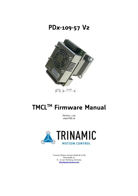
PDx-109-57 V2<br />
TMCL TM <strong>Firmware</strong> <strong>Manual</strong><br />
Version: 1.00<br />
2009-FEB-18<br />
<strong>Trinamic</strong> Motion Control GmbH & Co KG<br />
Sternstraße 67<br />
D - 20 357 Hamburg, Germany<br />
http://www.trinamic.com
PD-109-57 V2 TMCL <strong>Firmware</strong> <strong>Manual</strong> (V1.00/2010-FEB-18) 2<br />
Table of contents<br />
1 Life support policy ....................................................................................................................................................... 4<br />
2 Features ........................................................................................................................................................................... 5<br />
3 Order codes .................................................................................................................................................................... 7<br />
4 Overview ......................................................................................................................................................................... 8<br />
5 Putting the PDx-109-57 V2 into operation ............................................................................................................ 9<br />
5.1 Starting up ............................................................................................................................................................. 9<br />
5.2 Testing with a simple TMCL program ....................................................................................................... 11<br />
5.3 Operating the PANdrive in direct mode ................................................................................................. 12<br />
6 TMCL and TMCL-IDE ................................................................................................................................................ 13<br />
6.1 Binary command format .................................................................................................................................. 13<br />
6.2 Reply format ........................................................................................................................................................ 15<br />
6.2.1 Status codes .................................................................................................................................................. 16<br />
6.3 Stand-alone applications ................................................................................................................................. 16<br />
6.4 TMCL command overview ........................................................................................................................... 16<br />
6.4.1 Motion commands ...................................................................................................................................... 16<br />
6.4.2 Parameter commands ................................................................................................................................ 17<br />
6.4.3 I/O port commands..................................................................................................................................... 17<br />
6.4.4 Control commands ...................................................................................................................................... 17<br />
6.4.5 Calculation commands ............................................................................................................................... 18<br />
6.5 TMCL List of commands ............................................................................................................................... 19<br />
6.6 The ASCII interface ........................................................................................................................................... 21<br />
6.6.1 Format of the command line ................................................................................................................... 21<br />
6.6.2 Format of a reply ......................................................................................................................................... 21<br />
6.6.3 Commands that can be used in ASCII mode ..................................................................................... 21<br />
6.6.4 Configuring the ASCII interface .............................................................................................................. 22<br />
6.7 Commands ........................................................................................................................................................... 23<br />
6.7.1 ROR (rotate right)......................................................................................................................................... 23<br />
6.7.2 ROL (rotate left) ............................................................................................................................................ 24<br />
6.7.3 MST (motor stop) ......................................................................................................................................... 25<br />
6.7.4 MVP (move to position) ............................................................................................................................. 26<br />
6.7.5 SAP (set axis parameter) ........................................................................................................................... 28<br />
6.7.6 GAP (get axis parameter) ........................................................................................................................... 32<br />
6.7.7 STAP (store axis parameter) ..................................................................................................................... 37<br />
6.7.8 RSAP (restore axis parameter) ................................................................................................................. 40<br />
6.7.9 SGP (set global parameter) ....................................................................................................................... 43<br />
6.7.10 GGP (get global parameter) ...................................................................................................................... 46<br />
6.7.11 STGP (store global parameter) ................................................................................................................. 49<br />
6.7.12 RSGP (restore global parameter) ............................................................................................................. 51<br />
6.7.13 RFS (reference search) ................................................................................................................................ 53<br />
6.7.14 SIO (set output) ........................................................................................................................................... 54<br />
6.7.15 GIO (get input/output) .............................................................................................................................. 55<br />
6.7.16 CALC (calculate) ............................................................................................................................................ 57<br />
6.7.17 COMP (compare) ........................................................................................................................................... 58<br />
6.7.18 JC (jump conditional).................................................................................................................................. 59<br />
6.7.19 JA (jump always).......................................................................................................................................... 60<br />
6.7.20 CSUB (call subroutine) ................................................................................................................................ 61<br />
6.7.21 RSUB (return from subroutine) ................................................................................................................ 62<br />
6.7.22 WAIT (wait for an event to occur) ......................................................................................................... 63<br />
6.7.23 STOP (stop TMCL program execution) ............................................................................................... 64<br />
6.7.24 SCO (set coordinate) ................................................................................................................................... 65<br />
6.7.25 GCO (get coordinate) .................................................................................................................................. 66<br />
6.7.26 CCO (capture coordinate) ........................................................................................................................... 67<br />
6.7.27 CALCX (calculate using the X register) .................................................................................................. 68<br />
6.7.28 AAP (accumulator to axis parameter) .................................................................................................... 69<br />
6.7.29 AGP (accumulator to global parameter) ............................................................................................... 73<br />
6.7.30 CLE (clear error flags) ................................................................................................................................. 77<br />
Copyright © 2010, TRINAMIC Motion Control GmbH & Co. KG
PD-109-57 V2 TMCL <strong>Firmware</strong> <strong>Manual</strong> (V1.00/2010-FEB-18) 3<br />
6.7.31 Customer specific TMCL command extension (UF0…UF7/user function) .................................. 78<br />
6.7.32 Request target position reached event ................................................................................................. 79<br />
6.7.33 BIN (return to binary mode) .................................................................................................................... 80<br />
6.7.34 TMCL Control Functions ......................................................................................................................... 81<br />
7 Axis parameters .......................................................................................................................................................... 83<br />
7.1 Axis parameters .................................................................................................................................................. 83<br />
8 Global parameters ...................................................................................................................................................... 87<br />
8.1 Bank 0 ................................................................................................................................................................... 87<br />
8.2 Bank 1 ................................................................................................................................................................... 89<br />
8.3 Bank 2 ................................................................................................................................................................... 90<br />
9 Hints and tips .............................................................................................................................................................. 91<br />
9.1 Reference search ................................................................................................................................................ 91<br />
9.2 Stall detection ..................................................................................................................................................... 92<br />
9.3 Fixing microstep errors .................................................................................................................................... 92<br />
10 Revision history .......................................................................................................................................................... 93<br />
10.1 <strong>Firmware</strong> revision .............................................................................................................................................. 93<br />
10.2 Document revision ............................................................................................................................................ 93<br />
11 References..................................................................................................................................................................... 93<br />
Copyright © 2010, TRINAMIC Motion Control GmbH & Co. KG
PD-109-57 V2 TMCL <strong>Firmware</strong> <strong>Manual</strong> (V1.00/2010-FEB-18) 4<br />
1 Life support policy<br />
TRINAMIC Motion Control GmbH & Co. KG does not<br />
authorize or warrant any of its products for use in life<br />
support systems, without the specific written consent of<br />
TRINAMIC Motion Control GmbH & Co. KG.<br />
Life support systems are equipment intended to support or<br />
sustain life, and whose failure to perform, when properly<br />
used in accordance with instructions provided, can be<br />
reasonably expected to result in personal injury or death.<br />
© TRINAMIC Motion Control GmbH & Co. KG 2010<br />
Information given in this data sheet is believed to be<br />
accurate and reliable. However neither responsibility is<br />
assumed for the consequences of its use nor for any<br />
infringement of patents or other rights of third parties,<br />
which may result from its use.<br />
Specifications are subject to change without notice.<br />
Copyright © 2010, TRINAMIC Motion Control GmbH & Co. KG
PD-109-57 V2 TMCL <strong>Firmware</strong> <strong>Manual</strong> (V1.00/2010-FEB-18) 5<br />
2 Features<br />
The PANdrive PDx-109-57 V2 features a full mechatronic solution including a 57mm flange motor. It is<br />
based on the TMCM-109-57 electronics and offers RS232 and RS485 interfaces. The power supply, the<br />
interface and the multipurpose I/Os can be connected via two pluggable screw terminal connectors.<br />
With the stallGuard feature it is possible to detect motor overload or motor stall.<br />
The TMCM-109-57 comes with the PC based software development environment TMCL-IDE for the<br />
<strong>Trinamic</strong> Motion Control Language (TMCL). Using predefined TMCL high level commands like move<br />
to position or constant rotation a rapid and fast development of motion control applications is<br />
guaranteed. Communication traffic is kept very low since all time critical operations, e.g. ramp<br />
calculation are performed onboard. The TMCL program can be stored in the on-board EEPROM for<br />
stand-alone operation. The firmware of the module can be updated via the serial interface.<br />
Applications<br />
decentralized mechatronic drive with integrated intelligence<br />
high-precision drives with high dynamics and torque<br />
Electrical data<br />
18V to 55V motor supply voltage for highest motor dynamics<br />
up to 3.5A RMS nominal motor current<br />
Motor data<br />
all PANdrive Motors optimized for 3.0A RMS motor current<br />
flange max. 56.5mm x 56.5mm<br />
D-cut of 15mm length and 0.5mm depth<br />
more specifications:<br />
Specifications Parameter Units QSH5718<br />
-41-28-055 -51-28-101 56-28-126 -76-28-189<br />
Number of Leads N˚ 4 4 4 4<br />
Step Angle ˚ 1.8 1.8 1.8 1.8<br />
Step Angle Accuracy % 5 5 5 5<br />
Rated Voltage VRATED V 2 2.3 2.5 3.2<br />
Rated Phase Current IRMS RATED A 2.8 2.8 2.8 2.8<br />
Phase Resistance at 20°C RCOIL Ω 0.7 0.83 0.9 1.13<br />
Phase Inductance (typ.) mH 1.4 2.2 2.5 3.6<br />
Holding Torque Nm 0.55 1.01 1.26 1.89<br />
Detent Torque Nm 0.020 0.035 0.039 0.066<br />
Rotor Inertia g cm2 120 275 300 480<br />
Insulation Class B B B B<br />
Max. applicable voltage V 75 75 75 75<br />
Max. radial force<br />
(20mm from front flange)<br />
N 75 75 75 75<br />
Max. axial force N 15 15 15 15<br />
Weight kg 0.45 0.65 0.7 1<br />
Length mm 41 51 56 76<br />
Temp. Rise (rated current,<br />
2 phase on)<br />
˚C +80 max +80 max +80 max +80 max<br />
Ambient Temperature ˚C -20 +50 -20 +50 -20 +50 -20 +50<br />
Table 2.1: Specifications of the PANdrive motors<br />
Copyright © 2010, TRINAMIC Motion Control GmbH & Co. KG
PD-109-57 V2 TMCL <strong>Firmware</strong> <strong>Manual</strong> (V1.00/2010-FEB-18) 6<br />
Interface<br />
RS232, RS485<br />
2 inputs for reference and stop switches<br />
3 general purpose inputs and 1 general purpose output<br />
Features<br />
up to 16 times microstepping<br />
memory for 2048 TMCL commands<br />
automatic ramp generation in hardware<br />
on the fly alteration of motion parameters (e.g. position, velocity, acceleration)<br />
stallGuard for sensorless motor stall detection<br />
optically isolated inputs for two general purpose inputs and the disable input<br />
dynamic current control<br />
Software<br />
stand-alone operation using TMCL or remote controlled operation<br />
PC-based application development software TMCL-IDE included<br />
Other<br />
Pluggable screw terminal connectors for all external signals<br />
RoHS compliant latest from July 1 st , 2006<br />
Copyright © 2010, TRINAMIC Motion Control GmbH & Co. KG
PD-109-57 V2 TMCL <strong>Firmware</strong> <strong>Manual</strong> (V1.00/2010-FEB-18) 7<br />
3 Order codes<br />
Order code Description Dimensions<br />
PD1-109-57-RS PANdrive 0.55Nm 93.6 x 57.2 x 86<br />
PD2-109-57-RS PANdrive 1.01Nm 103.6 x 57.2 x 86<br />
PD3-109-57-RS PANdrive 1.26Nm 108.6 x 57.2 x 86<br />
PD4-109-57-RS PANdrive 1.89Nm 128.6 x 57.2 x 86<br />
Option Host interface<br />
RS RS232 and RS485<br />
Table 3.1: Order codes<br />
Copyright © 2010, TRINAMIC Motion Control GmbH & Co. KG
PD-109-57 V2 TMCL <strong>Firmware</strong> <strong>Manual</strong> (V1.00/2010-FEB-18) 8<br />
4 Overview<br />
As with most TRINAMIC modules the software running on the microprocessor of the PD-109-57 V2 consists<br />
of two parts, a boot loader and the firmware itself. Whereas the boot loader is installed during production<br />
and testing at TRINAMIC and remains – normally – untouched throughout the whole lifetime, the firmware<br />
can be updated by the user. New versions can be downloaded free of charge from the TRINAMIC website<br />
(http://www.trinamic.com).<br />
The firmware shipped with this module is related to the standard TMCL firmware [TMCL] shipped with<br />
most of TRINAMIC modules with regard to protocol and commands. Corresponding, the module is based on<br />
the TMC428-I stepper motor controller and the TMC249 power driver and supports the standard TMCL with<br />
a special range of values.<br />
All commands and parameters available with this unit are explained on the following pages.<br />
Copyright © 2010, TRINAMIC Motion Control GmbH & Co. KG
PD-109-57 V2 TMCL <strong>Firmware</strong> <strong>Manual</strong> (V1.00/2010-FEB-18) 9<br />
5 Putting the PDx-109-57 V2 into operation<br />
Here you can find basic information for putting your PANdrive into operation. The text contains a simple<br />
example for a TMCL TM program and a short description of operating the module in direct mode.<br />
The things you need:<br />
PDx-109-57 V2<br />
Interface: Either use RS232 directly from PC or RS485 with a converter (add termination network and<br />
set telegram pause time if necessary).<br />
Nominal supply voltage +24V… 48V DC for your module<br />
TMCL-IDE program and PC<br />
Precautions:<br />
Do not mix up connections or short-circuit pins.<br />
Avoid bounding I/O wires with motor power wires as this may cause noise picked up from the<br />
motor supply.<br />
Do not exceed the maximum power supply of 55V DC.<br />
Do not connect or disconnect the motor while powered!<br />
Start with power supply OFF!<br />
5.1 Starting up<br />
The following figure will show you which connectors have to be used.<br />
RS232<br />
5<br />
GND<br />
+5V<br />
StopL<br />
StopR<br />
GPI<br />
GPO<br />
RXD<br />
TXD<br />
IF_select<br />
GND<br />
3<br />
2<br />
-<br />
RS232<br />
zu<br />
RS485<br />
+<br />
GPO<br />
Shutdown<br />
GPI 1<br />
GPI 2<br />
OC_GND<br />
RS485-<br />
RS485+<br />
RS485-<br />
RS485+<br />
GND<br />
GND<br />
+VM<br />
Copyright © 2010, TRINAMIC Motion Control GmbH & Co. KG<br />
Connector 1<br />
Terminal 1<br />
Connector 2<br />
Terminal 1
PD-109-57 V2 TMCL <strong>Firmware</strong> <strong>Manual</strong> (V1.00/2010-FEB-18) 10<br />
1. Connect the interface RS232 or RS485<br />
a. RS232<br />
Use connector 2 for connecting the RS232 interface. Please have a look to the figure above<br />
how to do it.<br />
b. RS485<br />
Use connector 1 for connecting the RS485 interface. Using the RS485 interface has to<br />
be enabled via the interface selection input (connector2, terminal 2: IF select).<br />
Interface selection (IF): - leave open for RS232<br />
- connect to ground for RS485<br />
2. Connect the power supply<br />
Use connector 1 for connecting the power supply to PDx-109-57 VS.<br />
3. Switch ON the power supply<br />
The power LED flashes now.<br />
If this does not occur, switch power OFF and check your connections as well as the power<br />
supply.<br />
4. Start the TMCL-IDE software development environment<br />
The TMCL-IDE is available on the TechLibCD and on www.trinamic.com.<br />
Installing the TMCL-IDE:<br />
Make sure the COM port you intend to use is not blocked by another program.<br />
Open TMCL-IDE by clicking TMCL.exe.<br />
Choose Setup and Options and thereafter the Connection tab.<br />
Copyright © 2010, TRINAMIC Motion Control GmbH & Co. KG
PD-109-57 V2 TMCL <strong>Firmware</strong> <strong>Manual</strong> (V1.00/2010-FEB-18) 11<br />
Choose COM port and type with fitting parameters (baud rate 9600 for RS232). Click OK.<br />
5.2 Testing with a simple TMCL program<br />
Open the file test2.tmc. The following source code appears on the screen:<br />
A description for the TMCL commands can be found in Appendix A.<br />
//A simple example for using TMCL and TMCL-IDE<br />
ROL 0, 500 //Rotate motor 0 with speed 500<br />
WAIT TICKS, 0, 500<br />
MST 0<br />
ROR 0, 250 //Rotate motor 1 with 250<br />
WAIT TICKS, 0, 500<br />
MST 0<br />
SAP 4, 0, 500 //Set max. Velocity<br />
SAP 5, 0, 50 //Set max. Acceleration<br />
Loop: MVP ABS, 0, 10000 //Move to Position 10000<br />
WAIT POS, 0, 0 //Wait until position reached<br />
MVP ABS, 0, -10000 //Move to Position -10000<br />
WAIT POS, 0, 0 //Wait until position reached<br />
JA Loop //Infinite Loop<br />
Assemble<br />
Download Run<br />
Copyright © 2010, TRINAMIC Motion Control GmbH & Co. KG<br />
Stop<br />
1. Click on icon Assemble to convert the TMCL into binary code.<br />
2. Then download the program to the TMCM-109 module via the icon Download.<br />
3. Press icon Run. The desired program will be executed.<br />
4. Click Stop button to stop the program.
PD-109-57 V2 TMCL <strong>Firmware</strong> <strong>Manual</strong> (V1.00/2010-FEB-18) 12<br />
5.3 Operating the PANdrive in direct mode<br />
1. Start TMCL Direct Mode.<br />
Direct Mode<br />
2. If the communication is established the TMCM-109 is automatically detected. If the module is not<br />
detected, please check all points above (cables, interface, power supply, COM port, baud rate).<br />
3. Issue a command by choosing instruction, type (if necessary), motor, and value and click Execute<br />
to send it to the module.<br />
Examples:<br />
ROR rotate right, motor 0, value 500 -> Click Execute. The motor is rotating now.<br />
MST motor stop, motor 0 -> Click Execute. The motor stops now.<br />
Please use the TMCL-IDE axis parameter calculation tool for getting best values.<br />
Copyright © 2010, TRINAMIC Motion Control GmbH & Co. KG
PD-109-57 V2 TMCL <strong>Firmware</strong> <strong>Manual</strong> (V1.00/2010-FEB-18) 13<br />
6 TMCL and TMCL-IDE<br />
The TMCM-109 module supports TMCL direct mode (binary commands or ASCII interface) and stand-alone<br />
TMCL program execution. You can store up to 2048 TMCL instructions on it.<br />
In direct mode the TMCL communication over RS232 and RS485 follows a strict master/slave relationship.<br />
That is, a host computer (e.g. PC/PLC) acting as the interface bus master will send a command to the<br />
module. The TMCL interpreter on it will then interpret this command, do the initialization of the motion<br />
controller, read inputs and write outputs or whatever is necessary according to the specified command. As<br />
soon as this step has been done, the module will send a reply back over RS232/RS485 to the bus master.<br />
The master should not transfer the next command till then. Normally, the module will just switch to<br />
transmission and occupy the bus for a reply, otherwise it will stay in receive mode. It will not send any<br />
data over the interface without receiving a command first. This way, any collision on the bus will be<br />
avoided when there are more than two nodes connected to a single bus.<br />
The <strong>Trinamic</strong> Motion Control Language (TMCL) provides a set of structured motion control commands.<br />
Every motion control command can be given by a host computer or can be stored in an EEPROM on the<br />
TMCM-109 to form programs that run stand-alone on the module. For this purpose there are not only motion<br />
control commands but also commands to control the program structure (like conditional jumps, compare<br />
and calculating).<br />
Every command has a binary representation and a mnemonic:<br />
The binary format is used to send commands from the host to a module in direct mode.<br />
The mnemonic format is used for easy usage of the commands when developing stand-alone<br />
TMCL applications with the TMCL-IDE (IDE means Integrated Development Environment).<br />
There is also a set of configuration variables for the axis and for global parameters which allow individual<br />
configuration of nearly every function of a module. This manual gives a detailed description of all TMCL<br />
commands and their usage.<br />
6.1 Binary command format<br />
Every command has a mnemonic and a binary representation. When commands are sent from a host to a<br />
module, the binary format has to be used. Every command consists of a one-byte command field, a one-byte<br />
type field, a one-byte motor/bank field and a four-byte value field. So the binary representation of a<br />
command always has seven bytes.<br />
When a command is to be sent via RS232 or RS485 interface, it has to be enclosed by an address byte at the<br />
beginning and a checksum byte at the end. In this case it consists of nine bytes.<br />
Copyright © 2010, TRINAMIC Motion Control GmbH & Co. KG
PD-109-57 V2 TMCL <strong>Firmware</strong> <strong>Manual</strong> (V1.00/2010-FEB-18) 14<br />
The binary command format for RS232 and RS485 is as follows:<br />
Bytes Meaning<br />
1 Module address<br />
1 Command number<br />
1 Type number<br />
1 Motor or Bank number<br />
4 Value (MSB first!)<br />
1 Checksum*<br />
*The checksum is calculated by adding up all the other bytes using an 8-bit addition.<br />
Checksum calculation<br />
As mentioned above, the checksum is calculated by adding up all bytes (including the module address byte)<br />
using 8-bit addition. Here are two examples to show how to do this:<br />
in C:<br />
unsigned char i, Checksum;<br />
unsigned char Command[9];<br />
//Set the “Command” array to the desired command<br />
Checksum = Command[0];<br />
for(i=1; i
PD-109-57 V2 TMCL <strong>Firmware</strong> <strong>Manual</strong> (V1.00/2010-FEB-18) 15<br />
6.2 Reply format<br />
Every time a command has been sent to a module, the module sends a reply.<br />
The reply format for RS232 and RS485 is as follows:<br />
Bytes Meaning<br />
1 Reply address<br />
1 Module address<br />
1 Status (e.g. 100 means no error)<br />
1 Command number<br />
4 Value (MSB first!)<br />
1 Checksum*<br />
*The checksum is also calculated by adding up all the other bytes using an 8-bit addition.<br />
Do not send the next command before you have received the reply!<br />
Copyright © 2010, TRINAMIC Motion Control GmbH & Co. KG
PD-109-57 V2 TMCL <strong>Firmware</strong> <strong>Manual</strong> (V1.00/2010-FEB-18) 16<br />
6.2.1 Status codes<br />
The reply contains a status code.<br />
The status code can have one of the following values:<br />
Code Meaning<br />
100 Successfully executed, no error<br />
101 Command loaded into TMCL<br />
program EEPROM<br />
1 Wrong checksum<br />
2 Invalid command<br />
3 Wrong type<br />
4 Invalid value<br />
5 Configuration EEPROM locked<br />
6 Command not available<br />
6.3 Stand-alone applications<br />
The module is equipped with an EEPROM for storing TMCL applications. You can use the TMCL-IDE for<br />
developing stand-alone TMCL applications. You can load your program down into the EEPROM and then<br />
they will run on the module. The TMCL-IDE contains an editor and a TMCL assembler where the<br />
commands can be entered using their mnemonic format. They will be assembled automatically into their<br />
binary representations. Afterwards this code can be downloaded into the module to be executed there.<br />
6.4 TMCL command overview<br />
In this section a short overview of the TMCL commands is given.<br />
6.4.1 Motion commands<br />
These commands control the motion of the motor. They are the most important commands and can be used<br />
in direct mode or in stand-alone mode.<br />
Mnemonic Command<br />
number<br />
Meaning<br />
ROL 2 Rotate left<br />
ROR 1 Rotate right<br />
MVP 4 Move to position<br />
MST 3 Motor stop<br />
RFS 13 Reference search<br />
SCO 30 Store coordinate<br />
CCO 32 Capture coordinate<br />
GCO 31 Get coordinate<br />
Copyright © 2010, TRINAMIC Motion Control GmbH & Co. KG
PD-109-57 V2 TMCL <strong>Firmware</strong> <strong>Manual</strong> (V1.00/2010-FEB-18) 17<br />
6.4.2 Parameter commands<br />
These commands are used to set, read and store axis parameters or global parameters. Axis parameters can<br />
be set independently for the axis, whereas global parameters control the behavior of the module itself.<br />
These commands can also be used in direct mode and in stand-alone mode.<br />
Mnemonic Command<br />
number<br />
Meaning<br />
SAP 5 Set axis parameter<br />
GAP 6 Get axis parameter<br />
STAP 7 Store axis parameter into EEPROM<br />
RSAP 8 Restore axis parameter from EEPROM<br />
SGP 9 Set global parameter<br />
GGP 10 Get global parameter<br />
STGP 11 Store global parameter into EEPROM<br />
RSGP 12 Restore global parameter from EEPROM<br />
6.4.3 I/O port commands<br />
These commands control the external I/O ports and can be used in direct mode and in stand-alone mode.<br />
Mnemonic Command<br />
number<br />
Meaning<br />
SIO 14 Set output<br />
GIO 15 Get input<br />
6.4.4 Control commands<br />
These commands are used to control the program flow (loops, conditions, jumps etc.). It does not make<br />
sense to use them in direct mode. They are intended for stand-alone mode only.<br />
Mnemonic Command<br />
number<br />
Meaning<br />
JA 22 Jump always<br />
JC 21 Jump conditional<br />
COMP 20 Compare accumulator with constant<br />
value<br />
CLE 36 Clear error flags<br />
CSUB 23 Call subroutine<br />
RSUB 24 Return from subroutine<br />
WAIT 27 Wait for a specified event<br />
STOP 28 End of a TMCL program<br />
Copyright © 2010, TRINAMIC Motion Control GmbH & Co. KG
PD-109-57 V2 TMCL <strong>Firmware</strong> <strong>Manual</strong> (V1.00/2010-FEB-18) 18<br />
6.4.5 Calculation commands<br />
These commands are intended to be used for calculations within TMCL applications. Although they could<br />
also be used in direct mode it does not make much sense to do so.<br />
Mnemonic Command<br />
number<br />
Meaning<br />
CALC 19 Calculate using the accumulator and a<br />
constant value<br />
CALCX 33 Calculate using the accumulator and the<br />
X register<br />
AAP 34 Copy accumulator to an axis parameter<br />
AGP 35 Copy accumulator to a global parameter<br />
For calculating purposes there is an accumulator (or accu or A register) and an X register. When executed in<br />
a TMCL program (in stand-alone mode), all TMCL commands that read a value store the result in the<br />
accumulator. The X register can be used as an additional memory when doing calculations. It can be loaded<br />
from the accumulator.<br />
When a command that reads a value is executed in direct mode the accumulator will not be affected. This<br />
means that while a TMCL program is running on the module (stand-alone mode), a host can still send<br />
commands like GAP, GGP or GIO to the module (e.g. to query the actual position of the motor) without<br />
affecting the flow of the TMCL program running on the module.<br />
Copyright © 2010, TRINAMIC Motion Control GmbH & Co. KG
PD-109-57 V2 TMCL <strong>Firmware</strong> <strong>Manual</strong> (V1.00/2010-FEB-18) 19<br />
6.5 TMCL List of commands<br />
The following TMCL commands are currently supported:<br />
Command Number Parameter Description<br />
ROR 1 , Rotate right with specified velocity<br />
ROL 2 , Rotate left with specified velocity<br />
MST 3 Stop motor movement<br />
MVP 4 ABS|REL|COORD, , <br />
SAP 5 , ,<br />
<br />
Copyright © 2010, TRINAMIC Motion Control GmbH & Co. KG<br />
Move to position (absolute or<br />
relative)<br />
Set axis parameter (motion control<br />
specific settings)<br />
GAP 6 , Get axis parameter (read out motion<br />
control specific settings)<br />
STAP 7 , Store axis parameter permanently<br />
(non volatile)<br />
RSAP 8 ; Restore axis parameter<br />
SGP 9 , ,<br />
<br />
Set global parameter (module specific<br />
settings, e.g. communication settings,<br />
or TMCL user variables)<br />
GGP 10 , Get global parameter (read out<br />
module specific settings e.g.<br />
communication settings, or TMCL<br />
user variables)<br />
STGP 11 , Store global parameter (TMCL user<br />
variables only)<br />
RSGP 12 , Restore global parameter (TMCL<br />
user variables only)<br />
RFS 13 START|STOP|STATUS, <br />
SIO 14 , ,<br />
<br />
Reference search<br />
Set digital output to specified value<br />
GIO 15 , Get value of analogue/digital input<br />
CALC 19 , Process accumulator & value<br />
COMP 20 Compare accumulator value<br />
JC 21 , Jump conditional<br />
JA 22 Jump absolute<br />
CSUB 23 Call subroutine<br />
RSUB 24 Return from subroutine<br />
WAIT 27 , ,<br />
<br />
Wait with further program execution<br />
STOP 28 Stop program execution<br />
SCO 30 , , <br />
Set coordinate
PD-109-57 V2 TMCL <strong>Firmware</strong> <strong>Manual</strong> (V1.00/2010-FEB-18) 20<br />
Command Number Parameter Description<br />
GCO 31 , <br />
CCO 32 , <br />
TMCL control commands:<br />
Instruction Description Type Mot/Bank Value<br />
128 – stop application a running TMCL standalone (don't care)<br />
application is stopped<br />
(don't care) (don't care)<br />
129 – run application TMCL execution is started (or 0 - run from (don't care) (don't care)<br />
continued)<br />
current address<br />
1 - run from<br />
specified address<br />
starting address<br />
130 – step application only the next command of a (don't care)<br />
TMCL application is executed<br />
(don't care) (don't care)<br />
131 – reset application the program counter is set to (don't care) (don't care) (don't care)<br />
zero, and the standalone<br />
132 – start download<br />
application is stopped (when<br />
running or stepped)<br />
target command execution is (don't care) (don't care) starting address<br />
mode<br />
stopped and all following<br />
of the application<br />
133 – quit download<br />
commands are transferred to<br />
the TMCL memory<br />
target command execution is (don't care) (don't care) (don't care)<br />
mode<br />
resumed<br />
134 – read TMCL the specified program memory (don't care) (don't care) <br />
135 – get application one of these values is (don't care) (don't care) (don't care)<br />
status<br />
returned:<br />
0 – stop<br />
1 – run<br />
2 – step<br />
3 – reset<br />
136 – get firmware return the module type and 0 – string (don’t care) (don’t care)<br />
version firmware revision either as a 1 – binary<br />
string or in binary format<br />
137 – restore factory reset all settings stored in the (don’t care) (don’t care) must be 1234<br />
settings EEPROM<br />
defaults<br />
to their factory<br />
This command does not send<br />
back a reply.<br />
138 – reserved<br />
139 – enter ASCII<br />
mode<br />
Enter ASCII command line (see<br />
chapter 6.6)<br />
Copyright © 2010, TRINAMIC Motion Control GmbH & Co. KG<br />
Get coordinate<br />
Capture coordinate<br />
CALCX 33 Process accumulator & X-register<br />
AAP 34 , Accumulator to axis parameter<br />
AGP 35 , Accumulator to global parameter<br />
(don’t care) (don’t care) (don’t care)
PD-109-57 V2 TMCL <strong>Firmware</strong> <strong>Manual</strong> (V1.00/2010-FEB-18) 21<br />
6.6 The ASCII interface<br />
TMCL also offers an ASCII interface that can be used to communicate with the module and to send some<br />
commands as text strings.<br />
The ASCII command line interface is entered by sending the binary command 139 (enter ASCII<br />
mode).<br />
Afterwards the commands are entered as in the TMCL-IDE. Please note that only those commands,<br />
which can be used in direct mode, also can be entered in ASCII mode.<br />
For leaving the ASCII mode and re-enter the binary mode enter the command BIN.<br />
6.6.1 Format of the command line<br />
As the first character, the address character has to be sent. The address character is A when the module<br />
address is 1, B for modules with address 2 and so on. After the address character there may be spaces (but<br />
this is not necessary). Then, send the command with its parameters. At the end of a command line a <br />
character has to be sent.<br />
Here are some examples for valid command lines:<br />
AMVP ABS, 0, 50000<br />
A MVP ABS, 0, 50000<br />
AROL 2, 500<br />
A MST 0<br />
ABIN<br />
These command lines would address the module with address 1. To address e.g. module 3, use address<br />
character C instead of A. The last command line shown above will make the module return to binary mode.<br />
6.6.2 Format of a reply<br />
After executing the command the module sends back a reply in ASCII format. This reply consists of:<br />
the address character of the host (host address that can be set in the module)<br />
the address character of the module<br />
the status code as a decimal number<br />
the return value of the command as a decimal number<br />
a character<br />
So, after sending AGAP 0, 1 the reply would be BA 100 –5000 if the actual position of axis 1 is –5000,<br />
the host address is set to 2 and the module address is 1. The value 100 is the status code 100 that means<br />
command successfully executed.<br />
6.6.3 Commands that can be used in ASCII mode<br />
The following commands can be used in ASCII mode: ROL, ROR, MST, MVP, SAP, GAP, STAP, RSAP, SGP, GGP,<br />
STGP, RSGP, RFS, SIO, GIO, SAC, SCO, GCO, CCO, UF0, UF1, UF2, UF3, UF4, UF5, UF6, and UF7.<br />
There are also special commands that are only available in ASCII mode:<br />
BIN: This command quits ASCII mode and returns to binary TMCL mode.<br />
RUN: This command can be used to start a TMCL program in memory.<br />
STOP: Stops a running TMCL application.<br />
Copyright © 2010, TRINAMIC Motion Control GmbH & Co. KG
PD-109-57 V2 TMCL <strong>Firmware</strong> <strong>Manual</strong> (V1.00/2010-FEB-18) 22<br />
6.6.4 Configuring the ASCII interface<br />
The module can be configured so that it starts up either in binary mode or in ASCII mode. Global<br />
parameter 67 is used for this purpose (please see also chapter 8.1). Bit 0 determines the startup mode: if<br />
this bit is set, the module starts up in ASCII mode, else it will start up in binary mode (default). Bit 4 and<br />
Bit 5 determine how the characters that are entered are echoed back. Normally, both bits are set to zero. In<br />
this case every character that is entered is echoed back when the module is addressed. Character can also<br />
be erased using the backspace character (press the backspace key in a terminal program). When bit 4 is set<br />
and bit 5 is clear the characters that are entered are not echoed back immediately but the entire line will be<br />
echoed back after the character has been sent. When bit 5 is set and bit 4 is clear there will be no<br />
echo, only the reply will be sent.<br />
Copyright © 2010, TRINAMIC Motion Control GmbH & Co. KG
PD-109-57 V2 TMCL <strong>Firmware</strong> <strong>Manual</strong> (V1.00/2010-FEB-18) 23<br />
6.7 Commands<br />
The module specific commands are explained in more detail on the following pages. They are listed<br />
according to their command number.<br />
6.7.1 ROR (rotate right)<br />
With this command the motor will be instructed to rotate with a specified velocity in right direction<br />
(increasing the position counter).<br />
Internal function: First, velocity mode is selected. Then, the velocity value is transferred to axis parameter<br />
#0 (target velocity).<br />
The module is based on the TMC428-I stepper motor controller and the TMC249 power driver. This makes<br />
possible choosing a velocity between 0 and 2047.<br />
Related commands: ROL, MST, SAP, GAP<br />
Mnemonic: ROR , <br />
Binary representation:<br />
INSTRUCTION NO. TYPE MOT/BANK VALUE<br />
1 (don't care) 0* <br />
0… 2047<br />
* Motor number is always O as only one motor is involved.<br />
Reply in direct mode:<br />
STATUS VALUE<br />
Example:<br />
Rotate right, velocity = 350<br />
Mnemonic: ROR 0, 350<br />
100 – OK (don't care)<br />
Binary:<br />
Byte Index 0 1 2 3 4 5 6 7 8<br />
Function Target- Instruction Type Motor/ Operand Operand Operand Operand Checksum<br />
address Number<br />
Bank Byte3 Byte2 Byte1 Byte0<br />
Value (hex) $01 $01 $00 $00 $00 $00 $01 $5e $61<br />
Copyright © 2010, TRINAMIC Motion Control GmbH & Co. KG
PD-109-57 V2 TMCL <strong>Firmware</strong> <strong>Manual</strong> (V1.00/2010-FEB-18) 24<br />
6.7.2 ROL (rotate left)<br />
With this command the motor will be instructed to rotate with a specified velocity (opposite direction<br />
compared to ROR, decreasing the position counter).<br />
Internal function: First, velocity mode is selected. Then, the velocity value is transferred to axis parameter<br />
#0 (target velocity).<br />
The module is based on the TMC428-I stepper motor controller and the TMC249 power driver. This makes<br />
possible choosing a velocity between 0 and 2047.<br />
Related commands: ROR, MST, SAP, GAP<br />
Mnemonic: ROL , <br />
Binary representation:<br />
INSTRUCTION NO. TYPE MOT/BANK VALUE<br />
2 (don't care) 0* <br />
0… 2047<br />
* Motor number is always O as only one motor is involved.<br />
Reply in direct mode:<br />
STATUS VALUE<br />
100 – OK (don't care)<br />
Example:<br />
Rotate left, velocity = 1200<br />
Mnemonic: ROL 0, 1200<br />
Binary:<br />
Byte Index 0 1 2 3 4 5 6 7 8<br />
Function Target- Instruction Type Motor/ Operand Operand Operand Operand Checksum<br />
address Number<br />
Bank Byte3 Byte2 Byte1 Byte0<br />
Value (hex) $01 $01 $00 $00 $00 $00 $04 $b0 $b6<br />
Copyright © 2010, TRINAMIC Motion Control GmbH & Co. KG
PD-109-57 V2 TMCL <strong>Firmware</strong> <strong>Manual</strong> (V1.00/2010-FEB-18) 25<br />
6.7.3 MST (motor stop)<br />
With this command the motor will be instructed to stop with deceleration ramp (soft stop). For information<br />
about hard stops refer to chapter 9 (hints and tips) please.<br />
Internal function: The axis parameter target velocity is set to zero.<br />
Related commands: ROL, ROR, SAP, GAP<br />
Mnemonic: MST <br />
Binary representation:<br />
INSTRUCTION NO. TYPE MOT/BANK VALUE<br />
3 (don't care) 0* (don't care)<br />
* Motor number is always O as only one motor is involved.<br />
Reply in direct mode:<br />
STATUS VALUE<br />
Example:<br />
Stop motor<br />
Mnemonic: MST 0<br />
100 – OK (don't care)<br />
Binary:<br />
Byte Index 0 1 2 3 4 5 6 7 8<br />
Function Target- Instruction Type Motor/ Operand Operand Operand Operand Checksum<br />
address Number<br />
Bank Byte3 Byte2 Byte1 Byte0<br />
Value (hex) $01 $03 $00 $00 $00 $00 $00 $00 $04<br />
Copyright © 2010, TRINAMIC Motion Control GmbH & Co. KG
PD-109-57 V2 TMCL <strong>Firmware</strong> <strong>Manual</strong> (V1.00/2010-FEB-18) 26<br />
6.7.4 MVP (move to position)<br />
With this command the motor will be instructed to move to a specified relative or absolute position or a<br />
pre-programmed coordinate. It will use the acceleration/deceleration ramp and the positioning speed<br />
programmed into the unit. This command is non-blocking – that is, a reply will be sent immediately after<br />
command interpretation and initialization of the motion controller. Further commands may follow without<br />
waiting for the motor reaching its end position. The maximum velocity and acceleration are defined by axis<br />
parameters #4 and #5.<br />
Three operation types are available:<br />
Moving to an absolute position in the range from - 8388608 to +8388607 (-2 23 to+2 23 -1).<br />
Starting a relative movement by means of an offset to the actual position. In this case, the new<br />
resulting position value must not exceed the above mentioned limits, too.<br />
Moving the motor to a (previously stored) coordinate (refer to SCO for details).<br />
Please note, that the distance between the actual position and the new one should not be more than<br />
8388607 microsteps. Otherwise the motor will run in the wrong direction for taking a shorter way. If<br />
the value is exactly 8388608 the motor maybe stops.<br />
Internal function: A new position value is transferred to the axis parameter #2 target position.<br />
Related commands: SAP, GAP, SCO, CCO, GCO, and MST<br />
Mnemonic: MVP , , <br />
Binary representation:<br />
INSTRUCTION NO. TYPE MOT/BANK VALUE<br />
4 0 ABS – absolute 0* <br />
1 REL – relative 0* <br />
2 COORD –<br />
coordinate<br />
* Motor number is always O as only one motor is involved.<br />
Reply in direct mode:<br />
STATUS VALUE<br />
100 – OK (don't care)<br />
Example MVP ABS:<br />
Move motor to (absolute) position 9000<br />
Mnemonic: MVP ABS, 0, 9000<br />
Copyright © 2010, TRINAMIC Motion Control GmbH & Co. KG<br />
0*
PD-109-57 V2 TMCL <strong>Firmware</strong> <strong>Manual</strong> (V1.00/2010-FEB-18) 27<br />
Example MVP REL:<br />
Move motor from current position 1000 steps backward (move relative -1000)<br />
Mnemonic: MVP REL, 0, -1000<br />
Binary:<br />
Byte Index 0 1 2 3 4 5 6 7 8<br />
Function Target- Instruction Type Motor/ Operand Operand Operand Operand Checksum<br />
address Number<br />
Bank Byte3 Byte2 Byte1 Byte0<br />
Value (hex) $01 $04 $01 $00 $ff $ff $fc $18 $18<br />
Examples MVP COORD:<br />
Move motor to previously stored coordinate #8<br />
Mnemonic: MVP COORD, 0, 8<br />
Binary:<br />
Byte Index 0 1 2 3 4 5 6 7 8<br />
Function Target- Instruction Type Motor/ Operand Operand Operand Operand Checksum<br />
address Number<br />
Bank Byte3 Byte2 Byte1 Byte0<br />
Value (hex) $01 $04 $02 $00 $00 $00 $00 $08 $0f<br />
It is possible to use stall detection. Please see section 9.2 for details.<br />
When moving to a coordinate, the coordinate has to be set properly in advance with the help of the<br />
SCO command (see 6.7.24).<br />
Copyright © 2010, TRINAMIC Motion Control GmbH & Co. KG
PD-109-57 V2 TMCL <strong>Firmware</strong> <strong>Manual</strong> (V1.00/2010-FEB-18) 28<br />
6.7.5 SAP (set axis parameter)<br />
With this command most of the motion control parameters of the module can be specified. The settings will<br />
be stored in SRAM and therefore are volatile. That is, information will be lost after power off. Please use<br />
command STAP (store axis parameter) in order to store any setting permanently.<br />
Internal function: The parameter format is converted ignoring leading zeros (or ones for negative values).<br />
The parameter is transferred to the correct position in the appropriate device.<br />
Related commands: GAP, STAP, RSAP, AAP<br />
Mnemonic: SAP , , <br />
Binary representation:<br />
INSTRUCTION NO. TYPE MOT/BANK VALUE<br />
5 <br />
* Motor number is always O as only one motor is involved.<br />
Reply in direct mode:<br />
STATUS VALUE<br />
100 – OK (don't care)<br />
List of parameters, which can be used for SAP:<br />
Copyright © 2010, TRINAMIC Motion Control GmbH & Co. KG<br />
0* <br />
Please note, that for the binary representation has to be filled with the number<br />
and the has to be filled with a value from range.<br />
Number Axis Parameter Description Range [Unit]<br />
0 target (next) The desired position in position mode (see 2<br />
position ramp mode, no. 138).<br />
23<br />
[µsteps]<br />
1 actual position The current position of the motor. Should 2<br />
only be overwritten for reference point<br />
setting.<br />
23<br />
[µsteps]<br />
2 target (next) The desired speed in velocity mode (see ramp 2047<br />
speed<br />
mode, no. 138). In position mode, this<br />
parameter is set by hardware: to the<br />
maximum speed during acceleration, and to<br />
zero during deceleration and rest.<br />
3 actual speed The current rotation speed. 2047<br />
4 maximum<br />
positioning<br />
speed<br />
5 maximum<br />
acceleration<br />
6 absolute max.<br />
current<br />
Should not exceed the physically highest<br />
possible value. Adjust the pulse divisor (no.<br />
154), if the speed value is very low (
PD-109-57 V2 TMCL <strong>Firmware</strong> <strong>Manual</strong> (V1.00/2010-FEB-18) 29<br />
Number Axis Parameter Description Range [Unit]<br />
7 standby current The current limit two seconds after the motor 0… 1500<br />
has stopped.<br />
[mA]<br />
12 right limit switch If set, deactivates the stop function of the 0/1<br />
disable<br />
right switch<br />
13 left limit switch Deactivates the stop function of the left 0/1<br />
disable<br />
switch resp. reference switch if set.<br />
130 minimum speed Should always be set 1 to ensure exact 0…2047<br />
reaching of the target position. Normally no<br />
need to change!<br />
138 ramp mode Automatically set when using ROR, ROL, MST 0/1/2<br />
and MVP.<br />
0: position mode. Steps are generated, when<br />
the parameters actual position and target<br />
position differ. Trapezoidal speed ramps are<br />
provided.<br />
2: velocity mode. The motor will run<br />
140 microstep<br />
continuously and the speed will be changed<br />
with constant (maximum) acceleration, if the<br />
parameter target speed is changed.<br />
For special purposes, the soft mode (value 1)<br />
with exponential decrease of speed can be<br />
selected.<br />
0 – full step*)<br />
0… 6<br />
resolution 1 – half step*)<br />
2 – 4 microsteps<br />
3 – 8 microsteps<br />
4 – 16 microsteps<br />
5 – 32 microsteps**)<br />
6 – 64 microsteps**)<br />
Note that modifying this parameter will affect<br />
the rotation speed in the same relation:<br />
*) The full-step setting and the half-step<br />
setting are not optimized for use without an<br />
adapted microstepping table. These settings<br />
just step through the microstep table in steps<br />
of 64 respectively 32. To get real full stepping<br />
use axis parameter 211 or load an adapted<br />
microstepping table.<br />
**) If the module is specified for 16<br />
microsteps only, switching to 32 or 64<br />
microsteps brings an enhancement in<br />
141 ref. switch<br />
resolution and smoothness. The position<br />
counter will use the full resolution, but,<br />
however, the motor will resolve a maximum<br />
of 24 different microsteps only for the 32 or<br />
64 microstep units.<br />
For three-switch mode: a position range, 0… 4095<br />
tolerance where an additional switch (connected to the<br />
REFL input) won't cause motor stop. See<br />
section 9.1 for details.<br />
149 soft stop flag If cleared, the motor will stop immediately 0/1<br />
(disregarding motor limits), when the<br />
153 ramp divisor<br />
reference or limit switch is hit.<br />
The exponent of the scaling factor for the 0… 13<br />
ramp generator- should be de/incremented<br />
carefully (in steps of one).<br />
Copyright © 2010, TRINAMIC Motion Control GmbH & Co. KG
PD-109-57 V2 TMCL <strong>Firmware</strong> <strong>Manual</strong> (V1.00/2010-FEB-18) 30<br />
Number Axis Parameter Description Range [Unit]<br />
154 pulse divisor The exponent of the scaling factor for the 0… 13<br />
pulse (step) generator – should be<br />
193 referencing<br />
de/incremented carefully (in steps of one).<br />
1 – Only the left reference switch is searched. 1/2/3<br />
mode<br />
2 – The right switch is searched and<br />
afterwards the left switch is searched.<br />
3 – Three-switch-mode: the right switch is<br />
searched first and afterwards the reference<br />
switch will be searched.<br />
Please see chapter 6.7.13 for details on<br />
reference search.<br />
194 referencing For the reference search this value specifies 0… 8<br />
search speed the search speed as a fraction of the<br />
maximum velocity:<br />
0 – full speed<br />
1 – half of the maximum speed<br />
2 – a quarter of the maximum speed<br />
3 – 1/8 of the maximum speed (etc.)<br />
195 referencing Similar to parameter no. 194, the speed for 0… 8<br />
switch speed the switching point calibration can be<br />
203 mixed decay<br />
selected.<br />
If the actual velocity is above this threshold, 0… 2048<br />
threshold mixed decay will be used. This can also be set or -1<br />
to -1 which turns on mixed decay<br />
204 freewheeling<br />
permanently also in the rising part of the<br />
microstep wave. This can be used to fix<br />
microstep errors.<br />
Time after which the power to the motor will 0…65535<br />
be cut when its velocity has reached zero. 0 = never<br />
[msec]<br />
205 stall detection Stall detection threshold. Set it to 0 for no 0… 7<br />
threshold stall detection or to a value between 1 (low<br />
threshold) and 7 (high threshold). The motor<br />
will be stopped if the load value exceeds the<br />
stall detection threshold. Switch off mixed<br />
decay to get usable results.<br />
211 fullstep<br />
When exceeding this speed the driver will 0…2048<br />
threshold switch to real full step mode. To disable this<br />
feature set this parameter to zero or to a<br />
value greater than 2047.<br />
Setting a full step threshold allows higher<br />
motor torque of the motor at higher velocity.<br />
When experimenting with this in a given<br />
application, try to reduce the motor current in<br />
order to be able to reach a higher motor<br />
velocity!<br />
214 power down Standstill period before the current is changed 1… 65535<br />
delay<br />
down to standby current. The standard value [10msec]<br />
is 200 (value equates 2000msec).<br />
Please use the TMCL-IDE axis parameter calculation tool for getting best values.<br />
Copyright © 2010, TRINAMIC Motion Control GmbH & Co. KG
PD-109-57 V2 TMCL <strong>Firmware</strong> <strong>Manual</strong> (V1.00/2010-FEB-18) 31<br />
Example:<br />
Set the absolute maximum current to 200mA<br />
Mnemonic: SAP 6, 0, 200<br />
Binary:<br />
Byte Index 0 1 2 3 4 5 6 7 8<br />
Function Target- Instruction Type Motor/ Operand Operand Operand Operand Checksum<br />
address Number<br />
Bank Byte3 Byte2 Byte1 Byte0<br />
Value (hex) $01 $05 $06 $00 $00 $00 $00 $c8 $d4<br />
Copyright © 2010, TRINAMIC Motion Control GmbH & Co. KG
PD-109-57 V2 TMCL <strong>Firmware</strong> <strong>Manual</strong> (V1.00/2010-FEB-18) 32<br />
6.7.6 GAP (get axis parameter)<br />
Most parameters of the TMCM-109 can be adjusted individually. With this parameter they can be read out. In<br />
stand-alone mode the requested value is also transferred to the accumulator register for further processing<br />
purposes (such as conditioned jumps). In direct mode the value read is only output in the value field of the<br />
reply (without affecting the accumulator).<br />
Internal function: The parameter is read out of the correct position in the appropriate device. The parameter<br />
format is converted adding leading zeros (or ones for negative values).<br />
Related commands: SAP, STAP, AAP, RSAP<br />
Mnemonic: GAP , <br />
Binary representation:<br />
INSTRUCTION NO. TYPE MOT/BANK VALUE<br />
6 * (don't care)<br />
* Motor number is always O as only one motor is involved.<br />
Reply in direct mode:<br />
STATUS VALUE<br />
100 – OK (don't care)<br />
List of parameters, which can be used for GAP:<br />
Number Axis Parameter Description Range [Unit]<br />
0 target (next) The desired position in position mode (see 2<br />
position ramp mode, no. 138).<br />
23<br />
[µsteps]<br />
1 actual position The current position of the motor. Should 2<br />
only be overwritten for reference point<br />
setting.<br />
23<br />
[µsteps]<br />
2 target (next) The desired speed in velocity mode (see ramp 2047<br />
speed<br />
mode, no. 138). In position mode, this<br />
parameter is set by hardware: to the<br />
maximum speed during acceleration, and to<br />
zero during deceleration and rest.<br />
3 actual speed The current rotation speed. 2047<br />
4 maximum<br />
positioning<br />
speed<br />
5 maximum<br />
acceleration<br />
6 absolute max.<br />
current<br />
Should not exceed the physically highest<br />
possible value. Adjust the pulse divisor (no.<br />
154), if the speed value is very low (
PD-109-57 V2 TMCL <strong>Firmware</strong> <strong>Manual</strong> (V1.00/2010-FEB-18) 33<br />
Number Axis Parameter Description Range [Unit]<br />
8 target pos. Indicates that the actual position equals the 0/1<br />
reached target position.<br />
9 ref. switch status The logical state of the reference (left) switch.<br />
See the TMC 428 data sheet for the different<br />
switch modes. The default has two switch<br />
modes: the left switch as the reference<br />
switch, the right switch as a limit (stop)<br />
switch.<br />
0/1<br />
10 right limit switch The logical state of the (right) limit switch.<br />
status<br />
0/1<br />
11 left limit switch The logical state of the left limit switch (in 0/1<br />
status<br />
three switch mode)<br />
12 right limit switch If set, deactivates the stop function of the 0/1<br />
disable<br />
right switch<br />
13 left limit switch Deactivates the stop function of the left 0/1<br />
disable<br />
switch resp. reference switch if set.<br />
130 minimum speed Should always be set 1 to ensure exact 0…2047<br />
reaching of the target position. Normally no<br />
need to change!<br />
135 actual<br />
acceleration<br />
The current acceleration (read only). 0… 2047*<br />
138 ramp mode Automatically set when using ROR, ROL, MST 0/1/2<br />
and MVP.<br />
0: position mode. Steps are generated, when<br />
the parameters actual position and target<br />
position differ. Trapezoidal speed ramps are<br />
provided.<br />
2: velocity mode. The motor will run<br />
continuously and the speed will be changed<br />
with constant (maximum) acceleration, if the<br />
parameter target speed is changed.<br />
For special purposes, the soft mode (value 1)<br />
with exponential decrease of speed can be<br />
selected.<br />
Copyright © 2010, TRINAMIC Motion Control GmbH & Co. KG
PD-109-57 V2 TMCL <strong>Firmware</strong> <strong>Manual</strong> (V1.00/2010-FEB-18) 34<br />
Number Axis Parameter Description Range [Unit]<br />
140 microstep 0 – full step*)<br />
0…6<br />
resolution 1 – half step*)<br />
2 – 4 microsteps<br />
3 – 8 microsteps<br />
4 – 16 microsteps<br />
5 – 32 microsteps**)<br />
6 – 64 microsteps**)<br />
Note that modifying this parameter will affect<br />
the rotation speed in the same relation:<br />
*) The full-step setting and the half-step<br />
setting are not optimized for use without an<br />
adapted microstepping table. These settings<br />
just step through the microstep table in steps<br />
of 64 respectively 32. To get real full stepping<br />
use axis parameter 211 or load an adapted<br />
microstepping table.<br />
**) If the module is specified for 16<br />
microsteps only, switching to 32 or 64<br />
microsteps brings an enhancement in<br />
141 ref. switch<br />
resolution and smoothness. The position<br />
counter will use the full resolution, but,<br />
however, the motor will resolve a maximum<br />
of 24 different microsteps only for the 32 or<br />
64 microstep units.<br />
For three-switch mode: a position range, 0...4095<br />
tolerance where an additional switch (connected to the<br />
REFL input) won't cause motor stop. See<br />
section 9.1 for details.<br />
149 soft stop flag If cleared, the motor will stop immediately 0/1<br />
(disregarding motor limits), when the<br />
153 ramp divisor<br />
reference or limit switch is hit.<br />
The exponent of the scaling factor for the 0…13<br />
ramp generator- should be de/incremented<br />
carefully (in steps of one).<br />
154 pulse divisor The exponent of the scaling factor for the 0…13<br />
pulse (step) generator – should be<br />
193 referencing<br />
de/incremented carefully (in steps of one).<br />
1 – Only the left reference switch is searched. 1/2/3<br />
mode<br />
2 – The right switch is searched and<br />
afterwards the left switch is searched.<br />
3 – Three-switch-mode: the right switch is<br />
searched first and afterwards the reference<br />
switch will be searched.<br />
Please see chapter 6.7.13 for details on<br />
reference search.<br />
194 referencing For the reference search this value specifies 0…8<br />
search speed the search speed as a fraction of the<br />
maximum velocity:<br />
0 – full speed<br />
1 – half of the maximum speed<br />
2 – a quarter of the maximum speed<br />
3 – 1/8 of the maximum speed (etc.)<br />
195 referencing Similar to parameter no. 194, the speed for 0..8<br />
switch speed the switching point calibration can be<br />
selected.<br />
Copyright © 2010, TRINAMIC Motion Control GmbH & Co. KG
PD-109-57 V2 TMCL <strong>Firmware</strong> <strong>Manual</strong> (V1.00/2010-FEB-18) 35<br />
Number Axis Parameter Description Range [Unit]<br />
203 mixed decay<br />
threshold<br />
If the actual velocity is above this threshold,<br />
mixed decay will be used. This can also be set<br />
to -1 which turns on mixed decay<br />
permanently also in the rising part of the<br />
microstep wave. This can be used to fix<br />
microstep errors.<br />
204 freewheeling Time after which the power to the motor will<br />
be cut when its velocity has reached zero.<br />
205 stall detection<br />
threshold<br />
Stall detection threshold. Set it to 0 for no<br />
stall detection or to a value between 1 (low<br />
threshold) and 7 (high threshold). The motor<br />
will be stopped if the load value exceeds the<br />
stall detection threshold. Switch off mixed<br />
206<br />
decay to get usable results.<br />
actual load value Readout of the actual load value used for stall<br />
detection.<br />
208 Driver Error Flags<br />
of TMC249<br />
Bit<br />
7<br />
Name<br />
OT<br />
Function<br />
Overtemperature<br />
Remark<br />
1 = chip of due to<br />
211 fullstep<br />
threshold<br />
214 power down<br />
delay<br />
* Unit of acceleration:<br />
Copyright © 2010, TRINAMIC Motion Control GmbH & Co. KG<br />
6<br />
OTP<br />
W<br />
5 UV<br />
4 OCHS<br />
3 OLB<br />
2 OLA<br />
1 OCB<br />
0 OCA<br />
Temperature<br />
prewarning<br />
Driver<br />
undervoltage<br />
Overcurrent high<br />
side<br />
Open load<br />
bridge B<br />
Open load<br />
bridge A<br />
Overcurrent<br />
bridge B low<br />
side<br />
Overcurrent<br />
bridge A low<br />
side<br />
overtemperature<br />
1= prewarning<br />
temperature exceeded<br />
1 = undervoltage on VS<br />
3 PWM cycles with<br />
overcurrent within 63<br />
PWM cycles<br />
No PWM switch off for 14<br />
oscillator cycles<br />
No PWM switch off for 14<br />
oscillator cycles<br />
3 PWM cycles with<br />
overcurrent within 63<br />
PWM cycles<br />
3 PWM cycles with<br />
overcurrent within 63<br />
PWM cycles<br />
When exceeding this speed the driver will<br />
switch to real full step mode. To disable this<br />
feature set this parameter to zero or to a<br />
value greater than 2047.<br />
Setting a full step threshold allows higher<br />
motor torque of the motor at higher velocity.<br />
When experimenting with this in a given<br />
application, try to reduce the motor current in<br />
order to be able to reach a higher motor<br />
velocity!<br />
Standstill period before the current is changed<br />
down to standby current. The standard value<br />
is 200 (value equates 2000msec).<br />
0..2048<br />
or -1<br />
0…65535<br />
0 = never<br />
[msec]<br />
0…7<br />
0…7<br />
0… 7<br />
0..2048<br />
1… 65535<br />
[10msec]
PD-109-57 V2 TMCL <strong>Firmware</strong> <strong>Manual</strong> (V1.00/2010-FEB-18) 36<br />
Example:<br />
Get the actual position of motor<br />
Mnemonic: GAP 1, 0<br />
Binary:<br />
Byte Index 0 1 2 3 4 5 6 7 8<br />
Function Target- Instruction Type Motor/ Operand Operand Operand Operand Checksum<br />
address Number<br />
Bank Byte3 Byte2 Byte1 Byte0<br />
Value (hex) $01 $06 $01 $00 $00 $00 $00 $00 $08<br />
Reply:<br />
Byte Index 0 1 2 3 4 5 6 7 8<br />
Function Host- Target- Status Instruction Operand Operand Operand Operand Checksum<br />
address address<br />
Byte3 Byte2 Byte1 Byte0<br />
Value (hex) $02 $01 $64 $06 $00 $00 $02 $c7 $36<br />
status=no error, position=711<br />
Copyright © 2010, TRINAMIC Motion Control GmbH & Co. KG
PD-109-57 V2 TMCL <strong>Firmware</strong> <strong>Manual</strong> (V1.00/2010-FEB-18) 37<br />
6.7.7 STAP (store axis parameter)<br />
An axis parameter previously set with a Set Axis Parameter command (SAP) will be stored permanent. Most<br />
parameters are automatically restored after power up (refer to axis parameter list in chapter 7).<br />
Internal function: An axis parameter value stored in SRAM will be transferred to EEPROM and loaded from<br />
EEPORM after next power up.<br />
Related commands: SAP, RSAP, GAP, AAP<br />
Mnemonic: STAP , <br />
Binary representation:<br />
INSTRUCTION NO. TYPE MOT/BANK VALUE<br />
7 * 1 (don't care)* 2<br />
* 1 Motor number is always 0 as only one motor is involved.<br />
* 2 The value operand of this function has no effect. Instead, the currently used value (e.g. selected by SAP) is saved.<br />
Reply in direct mode:<br />
STATUS VALUE<br />
100 – OK (don't care)<br />
Parameter ranges:<br />
Parameter number Motor number Value<br />
s. chapter 7 0 s. chapter 7<br />
List of parameters, which can be used for STAP:<br />
Number Axis Parameter Description<br />
4 maximum<br />
positioning<br />
speed<br />
5 maximum<br />
acceleration<br />
6 absolute max.<br />
current<br />
Should not exceed the physically highest<br />
possible value. Adjust the pulse divisor (no.<br />
154), if the speed value is very low (
PD-109-57 V2 TMCL <strong>Firmware</strong> <strong>Manual</strong> (V1.00/2010-FEB-18) 38<br />
Number Axis Parameter Description<br />
138 ramp mode Automatically set when using ROR, ROL, MST<br />
and MVP.<br />
0: position mode. Steps are generated, when<br />
the parameters actual position and target<br />
position differ. Trapezoidal speed ramps are<br />
provided.<br />
2: velocity mode. The motor will run<br />
continuously and the speed will be changed<br />
with constant (maximum) acceleration, if the<br />
parameter target speed is changed.<br />
For special purposes, the soft mode (value 1)<br />
with exponential decrease of speed can be<br />
selected.<br />
140 microstep<br />
resolution<br />
0 – full step*)<br />
1 – half step*)<br />
2 – 4 microsteps<br />
3 – 8 microsteps<br />
4 – 16 microsteps<br />
5 – 32 microsteps**)<br />
6 – 64 microsteps**)<br />
Note that modifying this parameter will affect<br />
the rotation speed in the same relation:<br />
*) The full-step setting and the half-step<br />
setting are not optimized for use without an<br />
adapted microstepping table. These settings<br />
just step through the microstep table in steps<br />
of 64 respectively 32. To get real full stepping<br />
use axis parameter 211 or load an adapted<br />
microstepping table.<br />
**) If the module is specified for 16<br />
microsteps only, switching to 32 or 64<br />
microsteps brings an enhancement in<br />
resolution and smoothness. The position<br />
counter will use the full resolution, but,<br />
however, the motor will resolve a maximum<br />
of 24 different microsteps only for the 32 or<br />
64 microstep units.<br />
149 soft stop flag If cleared, the motor will stop immediately<br />
(disregarding motor limits), when the<br />
153 ramp divisor<br />
reference or limit switch is hit.<br />
The exponent of the scaling factor for the<br />
ramp generator- should be de/incremented<br />
carefully (in steps of one).<br />
154 pulse divisor The exponent of the scaling factor for the<br />
pulse (step) generator – should be<br />
de/incremented carefully (in steps of one).<br />
193 referencing<br />
mode<br />
1 – Only the left reference switch is searched.<br />
2 – The right switch is searched and<br />
afterwards the left switch is searched.<br />
3 – Three-switch-mode: the right switch is<br />
searched first and afterwards the reference<br />
switch will be searched.<br />
Please see chapter 6.7.13 for details on<br />
reference search.<br />
Copyright © 2010, TRINAMIC Motion Control GmbH & Co. KG
PD-109-57 V2 TMCL <strong>Firmware</strong> <strong>Manual</strong> (V1.00/2010-FEB-18) 39<br />
Number Axis Parameter Description<br />
194 referencing<br />
search speed<br />
195 referencing<br />
switch speed<br />
203 mixed decay<br />
threshold<br />
For the reference search this value specifies<br />
the search speed as a fraction of the<br />
maximum velocity:<br />
0 – full speed<br />
1 – half of the maximum speed<br />
2 – a quarter of the maximum speed<br />
3 – 1/8 of the maximum speed (etc.)<br />
Similar to parameter no. 194, the speed for<br />
the switching point calibration can be<br />
selected.<br />
If the actual velocity is above this threshold,<br />
mixed decay will be used. This can also be set<br />
to -1 which turns on mixed decay<br />
permanently also in the rising part of the<br />
microstep wave. This can be used to fix<br />
microstep errors.<br />
204 freewheeling Time after which the power to the motor will<br />
be cut when its velocity has reached zero.<br />
205 stall detection Stall detection threshold. Set it to 0 for no<br />
threshold stall detection or to a value between 1 (low<br />
threshold) and 7 (high threshold). The motor<br />
will be stopped if the load value exceeds the<br />
stall detection threshold. Switch off mixed<br />
decay to get usable results.<br />
211 fullstep<br />
When exceeding this speed the driver will<br />
threshold switch to real full step mode. To disable this<br />
feature set this parameter to zero or to a<br />
value greater than 2047.<br />
Setting a full step threshold allows higher<br />
motor torque of the motor at higher velocity.<br />
When experimenting with this in a given<br />
application, try to reduce the motor current in<br />
order to be able to reach a higher motor<br />
velocity!<br />
214 power down Standstill period before the current is changed<br />
delay<br />
down to standby current. The standard value<br />
is 200 (value equates 2000msec).<br />
Example:<br />
Store the maximum speed<br />
Mnemonic: STAP 4, 0<br />
Binary:<br />
Byte Index 0 1 2 3 4 5 6 7 8<br />
Function Target- Instruction Type Motor/ Operand Operand Operand Operand Checksum<br />
address Number<br />
Bank Byte3 Byte2 Byte1 Byte0<br />
Value (hex) $01 $07 $04 $00 $00 $00 $00 $00 $0c<br />
Note: The STAP command will not have any effect when the configuration EEPROM is locked (refer to<br />
8.1). In direct mode, the error code 5 (configuration EEPROM locked, see also section 6.2.1) will be<br />
returned in this case.<br />
Copyright © 2010, TRINAMIC Motion Control GmbH & Co. KG
PD-109-57 V2 TMCL <strong>Firmware</strong> <strong>Manual</strong> (V1.00/2010-FEB-18) 40<br />
6.7.8 RSAP (restore axis parameter)<br />
For all configuration-related axis parameters non-volatile memory locations are provided. By default, most<br />
parameters are automatically restored after power up (refer to axis parameter list in chapter 7). A single<br />
parameter that has been changed before can be reset by this instruction also.<br />
Internal function: The specified parameter is copied from the configuration EEPROM memory to its RAM<br />
location.<br />
Relate commands: SAP, STAP, GAP, and AAP<br />
Mnemonic: RSAP , <br />
Binary representation:<br />
INSTRUCTION NO. TYPE MOT/BANK VALUE<br />
8 * (don't care)<br />
* Motor number is always 0 as only one motor is involved.<br />
Reply structure in direct mode:<br />
STATUS VALUE<br />
100 – OK (don't care)<br />
List of parameters, which can be used for RSAP:<br />
Number Axis Parameter Description<br />
4 maximum<br />
positioning<br />
speed<br />
5 maximum<br />
acceleration<br />
6 absolute max.<br />
current<br />
Should not exceed the physically highest<br />
possible value. Adjust the pulse divisor (no.<br />
154), if the speed value is very low (
PD-109-57 V2 TMCL <strong>Firmware</strong> <strong>Manual</strong> (V1.00/2010-FEB-18) 41<br />
Number Axis Parameter Description<br />
138 ramp mode Automatically set when using ROR, ROL, MST<br />
and MVP.<br />
0: position mode. Steps are generated, when<br />
the parameters actual position and target<br />
position differ. Trapezoidal speed ramps are<br />
provided.<br />
2: velocity mode. The motor will run<br />
continuously and the speed will be changed<br />
with constant (maximum) acceleration, if the<br />
parameter target speed is changed.<br />
For special purposes, the soft mode (value 1)<br />
with exponential decrease of speed can be<br />
selected.<br />
140 microstep<br />
resolution<br />
0 – full step*)<br />
1 – half step*)<br />
2 – 4 microsteps<br />
3 – 8 microsteps<br />
4 – 16 microsteps<br />
5 – 32 microsteps**)<br />
6 – 64 microsteps**)<br />
Note that modifying this parameter will affect<br />
the rotation speed in the same relation:<br />
*) The full-step setting and the half-step<br />
setting are not optimized for use without an<br />
adapted microstepping table. These settings<br />
just step through the microstep table in steps<br />
of 64 respectively 32. To get real full stepping<br />
use axis parameter 211 or load an adapted<br />
microstepping table.<br />
**) If the module is specified for 16<br />
microsteps only, switching to 32 or 64<br />
microsteps brings an enhancement in<br />
resolution and smoothness. The position<br />
counter will use the full resolution, but,<br />
however, the motor will resolve a maximum<br />
of 24 different microsteps only for the 32 or<br />
64 microstep units.<br />
149 soft stop flag If cleared, the motor will stop immediately<br />
(disregarding motor limits), when the<br />
153 ramp divisor<br />
reference or limit switch is hit.<br />
The exponent of the scaling factor for the<br />
ramp generator- should be de/incremented<br />
carefully (in steps of one).<br />
154 pulse divisor The exponent of the scaling factor for the<br />
pulse (step) generator – should be<br />
de/incremented carefully (in steps of one).<br />
193 referencing<br />
mode<br />
1 – Only the left reference switch is searched.<br />
2 – The right switch is searched and<br />
afterwards the left switch is searched.<br />
3 – Three-switch-mode: the right switch is<br />
searched first and afterwards the reference<br />
switch will be searched.<br />
Please see chapter 6.7.13 for details on<br />
reference search.<br />
Copyright © 2010, TRINAMIC Motion Control GmbH & Co. KG
PD-109-57 V2 TMCL <strong>Firmware</strong> <strong>Manual</strong> (V1.00/2010-FEB-18) 42<br />
Number Axis Parameter Description<br />
194 referencing<br />
search speed<br />
195 referencing<br />
switch speed<br />
203 mixed decay<br />
threshold<br />
For the reference search this value specifies<br />
the search speed as a fraction of the<br />
maximum velocity:<br />
0 – full speed<br />
1 – half of the maximum speed<br />
2 – a quarter of the maximum speed<br />
3 – 1/8 of the maximum speed (etc.)<br />
Similar to parameter no. 194, the speed for<br />
the switching point calibration can be<br />
selected.<br />
If the actual velocity is above this threshold,<br />
mixed decay will be used. This can also be set<br />
to -1 which turns on mixed decay<br />
permanently also in the rising part of the<br />
microstep wave. This can be used to fix<br />
microstep errors.<br />
204 freewheeling Time after which the power to the motor will<br />
be cut when its velocity has reached zero.<br />
205 stall detection Stall detection threshold. Set it to 0 for no<br />
threshold stall detection or to a value between 1 (low<br />
threshold) and 7 (high threshold). The motor<br />
will be stopped if the load value exceeds the<br />
stall detection threshold. Switch off mixed<br />
decay to get usable results.<br />
211 fullstep<br />
When exceeding this speed the driver will<br />
threshold switch to real full step mode. To disable this<br />
feature set this parameter to zero or to a<br />
value greater than 2047.<br />
Setting a full step threshold allows higher<br />
motor torque of the motor at higher velocity.<br />
When experimenting with this in a given<br />
application, try to reduce the motor current in<br />
order to be able to reach a higher motor<br />
velocity!<br />
214 power down Standstill period before the current is changed<br />
delay<br />
down to standby current. The standard value<br />
is 200 (value equates 2000msec).<br />
Example:<br />
Restore the maximum current<br />
Mnemonic: RSAP 6, 0<br />
Binary:<br />
Byte Index 0 1 2 3 4 5 6 7 8<br />
Function Target- Instruction Type Motor/ Operand Operand Operand Operand Checksum<br />
address Number<br />
Bank Byte3 Byte2 Byte1 Byte0<br />
Value (hex) $01 $08 $06 $00 $00 $00 $00 $00 $0f<br />
Copyright © 2010, TRINAMIC Motion Control GmbH & Co. KG
PD-109-57 V2 TMCL <strong>Firmware</strong> <strong>Manual</strong> (V1.00/2010-FEB-18) 43<br />
6.7.9 SGP (set global parameter)<br />
With this command most of the module specific parameters not directly related to motion control can be<br />
specified and the TMCL user variables can be changed. Global parameters are related to the host interface,<br />
peripherals or application specific variables. The different groups of these parameters are organized in banks<br />
to allow a larger total number for future products. Currently, bank 0 and 1 are used for global parameters,<br />
and bank 2 is used for user variables.<br />
All module settings will automatically be stored non-volatile (internal EEPROM of the processor). The<br />
TMCL user variables will not be stored in the EEPROM automatically, but this can be done by using<br />
STGP commands.<br />
Internal function: the parameter format is converted ignoring leading zeros (or ones for negative values).<br />
The parameter is transferred to the correct position in the appropriate (on board) device.<br />
Related commands: GGP, STGP, RSGP, AGP<br />
Mnemonic: SGP , , <br />
Binary representation:<br />
INSTRUCTION NO. TYPE MOT/BANK VALUE<br />
9 <br />
Reply in direct mode:<br />
STATUS VALUE<br />
100 – OK (don't care)<br />
Global parameters of bank 0, which can be used for SGP:<br />
Copyright © 2010, TRINAMIC Motion Control GmbH & Co. KG<br />
<br />
Number Global parameter Description Range<br />
64 EEPROM magic Setting this parameter to a different value as $E4 will 0…255<br />
cause re-initialization of the axis and global parameters<br />
(to factory defaults) after the next power up. This is<br />
useful in case of miss-configuration.<br />
65 RS232 baud rate 0 9600 baud Default<br />
0…7<br />
1 14400 baud<br />
2 19200 baud<br />
3 28800 baud<br />
4 38400 baud<br />
5 57600 baud<br />
6 76800 baud Not supported by Windows!<br />
7 (115200 baud) 3.68% Error (111111 Bits/s)<br />
66 serial address The module (target) address for RS-232. 0…255<br />
67 ASCII mode<br />
Configure the TMCLTM ASCII interface:<br />
Bit 0: 0 – start up in binary (normal) mode<br />
1 – start up in ASCII mode<br />
Bits 4 and 5:<br />
00 – Echo back each character<br />
01 – Echo back complete command<br />
10 – Do not send echo, only send command reply<br />
73 configuration EEPROM Write: 1234 to lock the EEPROM, 4321 to unlock it. 0/1<br />
lock flag<br />
Read: 1=EEPROM locked, 0=EEPROM unlocked.<br />
75 telegram pause time Pause time before the reply via RS232 is sent. For RS232 0…255<br />
set to 0.<br />
76 serial host address Host address used in the reply telegrams sent back via 0…255<br />
RS232.
PD-109-57 V2 TMCL <strong>Firmware</strong> <strong>Manual</strong> (V1.00/2010-FEB-18) 44<br />
Number Global parameter Description Range<br />
77 auto start mode 0: Do not start TMCLTM application after power up<br />
(default).<br />
1: Start TMCLTM 0/1<br />
application automatically after power up.<br />
80 shutdown pin Select the functionality of the SHUTDOWN pin<br />
0…2<br />
functionality<br />
0 – no function<br />
1 – high active<br />
2 – low active<br />
81 TMCLTM code protection Protect a TMCLTM program against disassembling or<br />
overwriting.<br />
0 – no protection<br />
1 – protection against disassembling<br />
2 – protection against overwriting<br />
3 – protection against disassembling and overwriting<br />
If you switch off the protection against<br />
disassembling, the program will be erased first!<br />
Changing this value from 1 or 3 to 0 or 2, the TMCLTM 0,1,2,3<br />
program will be wiped off.<br />
132 tick timer A 32 bit counter that gets incremented by one every<br />
millisecond. It can also be reset to any start value.<br />
Global parameters of bank 1, which can be used for SGP:<br />
The global parameter bank 1 is normally not available. It may be used for customer specific extensions of<br />
the firmware. Together with user definable commands (see section 7.3) these variables form the interface<br />
between extensions of the firmware (written in C) and TMCL TM applications.<br />
Copyright © 2010, TRINAMIC Motion Control GmbH & Co. KG
PD-109-57 V2 TMCL <strong>Firmware</strong> <strong>Manual</strong> (V1.00/2010-FEB-18) 45<br />
Global parameters of bank 2, which can be used for SGP:<br />
Bank 2 contains general purpose 32 bit variables for the use in TMCL TM applications. They are located in RAM<br />
and can be stored to EEPROM. After booting, their values are automatically restored to the RAM.<br />
Number Global parameter Description Range<br />
0 general purpose variable #0 for use in TMCL applications -231…+231 1 general purpose variable #1 for use in TMCL applications -231…+231 2 general purpose variable #2 for use in TMCL applications -231…+231 3 general purpose variable #3 for use in TMCL applications -231…+231 4 general purpose variable #4 for use in TMCL applications -231…+231 5 general purpose variable #5 for use in TMCL applications -231…+231 6 general purpose variable #6 for use in TMCL applications -231…+231 7 general purpose variable #7 for use in TMCL applications -231…+231 8 general purpose variable #8 for use in TMCL applications -231…+231 9 general purpose variable #9 for use in TMCL applications -231…+231 10 general purpose variable #10 for use in TMCL applications -231…+231 11 general purpose variable #11 for use in TMCL applications -231…+231 12 general purpose variable #12 for use in TMCL applications -231…+231 13 general purpose variable #13 for use in TMCL applications -231…+231 14 general purpose variable #14 for use in TMCL applications -231…+231 15 general purpose variable #15 for use in TMCL applications -231…+231 16 general purpose variable #16 for use in TMCL applications -231…+231 17 general purpose variable #17 for use in TMCL applications -231…+231 18 general purpose variable #18 for use in TMCL applications -231…+231 19 general purpose variable #19 for use in TMCL applications -231…+231 20…55 general<br />
#20..#55<br />
purpose variables for use in TMCL applications -231…+231 Example:<br />
Set the serial address of the target device to 3<br />
Mnemonic: SGP 66, 0, 3<br />
Binary:<br />
Byte Index 0 1 2 3 4 5 6 7 8<br />
Function Target- Instruction Type Motor/ Operand Operand Operand Operand Checksum<br />
address Number<br />
Bank Byte3 Byte2 Byte1 Byte0<br />
Value (hex) $01 $09 $42 $00 $00 $00 $00 $03 $4f<br />
Please refer to chapter 8 for more information about bank 0 to 2.<br />
Copyright © 2010, TRINAMIC Motion Control GmbH & Co. KG
PD-109-57 V2 TMCL <strong>Firmware</strong> <strong>Manual</strong> (V1.00/2010-FEB-18) 46<br />
6.7.10 GGP (get global parameter)<br />
All global parameters can be read with this function. Global parameters are related to the host interface,<br />
peripherals or application specific variables. The different groups of these parameters are organized in banks<br />
to allow a larger total number for future products. Currently, bank 0 and 1 are used for global parameters,<br />
and bank 2 is used for user variables.<br />
Internal function: The parameter is read out of the correct position in the appropriate device. The parameter<br />
format is converted adding leading zeros (or ones for negative values).<br />
Related commands: SGP, STGP, RSGP, AGP<br />
Mnemonic: GGP , <br />
Binary representation:<br />
INSTRUCTION NO. TYPE MOT/BANK VALUE<br />
10 (don't care)<br />
Reply in direct mode:<br />
STATUS VALUE<br />
100 – OK (don't care)<br />
Global parameters of bank 0, which can be used for GGP:<br />
Number Global parameter Description Range<br />
64 EEPROM magic Setting this parameter to a different value as $E4 will 0…255<br />
cause re-initialization of the axis and global parameters<br />
(to factory defaults) after the next power up. This is<br />
useful in case of miss-configuration.<br />
65 RS232 baud rate 0 9600 baud Default<br />
0…7<br />
1 14400 baud<br />
2 19200 baud<br />
3 28800 baud<br />
4 38400 baud<br />
5 57600 baud<br />
6 76800 baud Not supported by Windows!<br />
7 (115200 baud) 3.68% Error (111111 Bits/s)<br />
66 serial address The module (target) address for RS-232/RS-485. 0…255<br />
67 ASCII mode<br />
Configure the TMCLTM ASCII interface:<br />
Bit 0: 0 – start up in binary (normal) mode<br />
1 – start up in ASCII mode<br />
Bits 4 and 5:<br />
00 – Echo back each character<br />
01 – Echo back complete command<br />
10 – Do not send echo, only send command reply<br />
73 configuration EEPROM Write: 1234 to lock the EEPROM, 4321 to unlock it. 0/1<br />
lock flag<br />
Read: 1=EEPROM locked, 0=EEPROM unlocked.<br />
75 telegram pause time Pause time before the reply via RS232 is sent. For RS232 0…255<br />
set to 0.<br />
76 serial host address Host address used in the reply telegrams sent back via 0…255<br />
RS232.<br />
77 auto start mode 0: Do not start TMCLTM application after power up<br />
(default).<br />
1: Start TMCLTM 0/1<br />
application automatically after power up.<br />
Copyright © 2010, TRINAMIC Motion Control GmbH & Co. KG
PD-109-57 V2 TMCL <strong>Firmware</strong> <strong>Manual</strong> (V1.00/2010-FEB-18) 47<br />
Number Global parameter Description Range<br />
80 shutdown pin Select the functionality of the SHUTDOWN pin<br />
0..2<br />
functionality<br />
0 – no function<br />
1 – high active<br />
2 – low active<br />
81 TMCLTM code protection Protect a TMCLTM program against disassembling or<br />
overwriting.<br />
0 – no protection<br />
1 – protection against disassembling<br />
2 – protection against overwriting<br />
3 – protection against disassembling and overwriting<br />
If you switch off the protection against<br />
disassembling, the program will be erased first!<br />
Changing this value from 1 or 3 to 0 or 2, the TMCLTM 0,1,2,3<br />
program will be wiped off.<br />
128 TMCLTM application 0 –stop<br />
0…3<br />
status<br />
1 – run<br />
2 – step<br />
3 – reset<br />
129 download mode 0 – normal mode<br />
1 – download mode<br />
0/1<br />
130 TMCLTM program<br />
counter<br />
The index of the currently executed TMCLTM instruction.<br />
132 tick timer A 32 bit counter that gets incremented by one every<br />
millisecond. It can also be reset to any start value.<br />
133 random number Choose a random number. Read only! 0…21474<br />
83647<br />
Global parameters of bank 1, which can be used for GGP:<br />
The global parameter bank 1 is normally not available. It may be used for customer specific extensions of<br />
the firmware. Together with user definable commands (see section 7.3) these variables form the interface<br />
between extensions of the firmware (written in C) and TMCL TM applications.<br />
Copyright © 2010, TRINAMIC Motion Control GmbH & Co. KG
PD-109-57 V2 TMCL <strong>Firmware</strong> <strong>Manual</strong> (V1.00/2010-FEB-18) 48<br />
Global parameters of bank 2, which can be used for GGP:<br />
Bank 2 contains general purpose 32 bit variables for the use in TMCL applications. They are located in RAM<br />
and can be stored to EEPROM. After booting, their values are automatically restored to the RAM.<br />
Number Global parameter Description Range<br />
0 general purpose variable #0 for use in TMCL applications -231…+231 1 general purpose variable #1 for use in TMCL applications -231…+231 2 general purpose variable #2 for use in TMCL applications -231…+231 3 general purpose variable #3 for use in TMCL applications -231…+231 4 general purpose variable #4 for use in TMCL applications -231…+231 5 general purpose variable #5 for use in TMCL applications -231…+231 6 general purpose variable #6 for use in TMCL applications -231…+231 7 general purpose variable #7 for use in TMCL applications -231…+231 8 general purpose variable #8 for use in TMCL applications -231…+231 9 general purpose variable #9 for use in TMCL applications -231…+231 10 general purpose variable #10 for use in TMCL applications -231…+231 11 general purpose variable #11 for use in TMCL applications -231…+231 12 general purpose variable #12 for use in TMCL applications -231…+231 13 general purpose variable #13 for use in TMCL applications -231…+231 14 general purpose variable #14 for use in TMCL applications -231…+231 15 general purpose variable #15 for use in TMCL applications -231…+231 16 general purpose variable #16 for use in TMCL applications -231…+231 17 general purpose variable #17 for use in TMCL applications -231…+231 18 general purpose variable #18 for use in TMCL applications -231…+231 19 general purpose variable #19 for use in TMCL applications -231…+231 20…55 general<br />
#20..#55<br />
purpose variables for use in TMCL applications -231…+231 Example:<br />
Get the serial address of the target device<br />
Mnemonic: GGP 66, 0<br />
Binary:<br />
Byte Index 0 1 2 3 4 5 6 7 8<br />
Function Target- Instruction Type Motor/ Operand Operand Operand Operand Checksum<br />
address Number<br />
Bank Byte3 Byte2 Byte1 Byte0<br />
Value (hex) $01 $0a $42 $00 $00 $00 $00 $00 $4d<br />
Reply:<br />
Byte Index 0 1 2 3 4 5 6 7 8<br />
Function Host- Target- Status Instruction Operand Operand Operand Operand Checksum<br />
address address<br />
Byte3 Byte2 Byte1 Byte0<br />
Value (hex) $02 $01 $64 $0a $00 $00 $00 $01 $72<br />
Status=no error, Value=1<br />
Please refer to chapter 8 for more information about bank 0 to 2.<br />
Copyright © 2010, TRINAMIC Motion Control GmbH & Co. KG
PD-109-57 V2 TMCL <strong>Firmware</strong> <strong>Manual</strong> (V1.00/2010-FEB-18) 49<br />
6.7.11 STGP (store global parameter)<br />
This command is used to store TMCL user variables permanently in the EEPROM of the module. Some<br />
global parameters are located in RAM memory, so without storing modifications are lost at power down.<br />
This instruction enables enduring storing. Most parameters are automatically restored after power up.<br />
Internal function: The specified parameter is copied from its RAM location to the configuration EEPROM.<br />
Related commands: SGP, GGP, RSGP, AGP<br />
Mnemonic: STGP , <br />
Binary representation:<br />
INSTRUCTION NO. TYPE MOT/BANK VALUE<br />
11 (don't care)<br />
Reply in direct mode:<br />
STATUS VALUE<br />
100 – OK (don't care)<br />
Global parameters of bank 0, which can be used for STGP:<br />
The global parameter bank 0 is not required for the STGP command, because these parameters are<br />
automatically stored with the SGP command in EEPROM.<br />
Global parameters of bank 1, which can be used for STGP:<br />
The global parameter bank 1 is normally not available, but can be used in customer specific extensions of<br />
the firmware.<br />
Global parameters of bank 2, which can be used for STGP:<br />
Bank 2 contains general purpose 32 bit variables for the use in TMCL applications. They are located in RAM<br />
and can be stored to EEPROM. After booting, their values are automatically restored to the RAM.<br />
Number Global parameter Description<br />
0 general purpose variable #0 for use in TMCL applications<br />
1 general purpose variable #1 for use in TMCL applications<br />
2 general purpose variable #2 for use in TMCL applications<br />
3 general purpose variable #3 for use in TMCL applications<br />
4 general purpose variable #4 for use in TMCL applications<br />
5 general purpose variable #5 for use in TMCL applications<br />
6 general purpose variable #6 for use in TMCL applications<br />
7 general purpose variable #7 for use in TMCL applications<br />
8 general purpose variable #8 for use in TMCL applications<br />
9 general purpose variable #9 for use in TMCL applications<br />
10 general purpose variable #10 for use in TMCL applications<br />
11 general purpose variable #11 for use in TMCL applications<br />
12 general purpose variable #12 for use in TMCL applications<br />
13 general purpose variable #13 for use in TMCL applications<br />
14 general purpose variable #14 for use in TMCL applications<br />
15 general purpose variable #15 for use in TMCL applications<br />
16 general purpose variable #16 for use in TMCL applications<br />
17 general purpose variable #17 for use in TMCL applications<br />
18 general purpose variable #18 for use in TMCL applications<br />
19 general purpose variable #19 for use in TMCL applications<br />
Copyright © 2010, TRINAMIC Motion Control GmbH & Co. KG
PD-109-57 V2 TMCL <strong>Firmware</strong> <strong>Manual</strong> (V1.00/2010-FEB-18) 50<br />
Number Global parameter Description<br />
20…55 general<br />
#20..#55<br />
purpose variables for use in TMCL applications<br />
Example:<br />
Store the user variable 5 in EEPROM.<br />
STGP 5, 2<br />
Binary:<br />
Byte Index 0 1 2 3 4 5 6 7 8<br />
Function Target- Instruction Type Motor/ Operand Operand Operand Operand Checksum<br />
address Number<br />
Bank Byte3 Byte2 Byte1 Byte0<br />
Value (hex) $01 $0b $05 $02 $00 $00 $00 $00 $13<br />
Note: The STAP command will not have any effect when the configuration EEPROM is locked (refer to<br />
8.1). In direct mode, the error code 5 (configuration EEPROM locked, see also section 6.2.1) will be<br />
returned in this case.<br />
Please refer to chapter 8 for more information about bank 0 to 2.<br />
Copyright © 2010, TRINAMIC Motion Control GmbH & Co. KG
PD-109-57 V2 TMCL <strong>Firmware</strong> <strong>Manual</strong> (V1.00/2010-FEB-18) 51<br />
6.7.12 RSGP (restore global parameter)<br />
With this command the contents of a TMCL user variable can be restored from the EEPROM. For all<br />
configuration-related axis parameters, non-volatile memory locations are provided. By default, most<br />
parameters are automatically restored after power up (see global parameter list in chapter 8). A single<br />
parameter that has been changed before can be reset by this instruction.<br />
Internal function: The specified parameter is copied from the configuration EEPROM memory to its RAM<br />
location.<br />
Relate commands: SAP, STAP, GAP, and AAP<br />
Mnemonic: RSAP , <br />
Binary representation:<br />
INSTRUCTION NO. TYPE MOT/BANK VALUE<br />
8 (don't care)<br />
Reply structure in direct mode:<br />
STATUS VALUE<br />
100 – OK (don't care)<br />
Global parameters of bank 0, which can be used for STGP:<br />
The global parameter bank 0 is not required for the STGP command, because these parameters are<br />
automatically stored with the SGP command in EEPROM.<br />
Global parameters of bank 1, which can be used for STGP:<br />
The global parameter bank 1 is normally not available, but can be used in customer specific extensions of<br />
the firmware.<br />
Global parameters of bank 2, which can be used for RSGP:<br />
Bank 2 contains general purpose 32 bit variables for the use in TMCL applications. They are located in RAM<br />
and can be stored to EEPROM. After booting, their values are automatically restored to the RAM.<br />
Number Global parameter Description<br />
0 general purpose variable #0 for use in TMCL applications<br />
1 general purpose variable #1 for use in TMCL applications<br />
2 general purpose variable #2 for use in TMCL applications<br />
3 general purpose variable #3 for use in TMCL applications<br />
4 general purpose variable #4 for use in TMCL applications<br />
5 general purpose variable #5 for use in TMCL applications<br />
6 general purpose variable #6 for use in TMCL applications<br />
7 general purpose variable #7 for use in TMCL applications<br />
8 general purpose variable #8 for use in TMCL applications<br />
9 general purpose variable #9 for use in TMCL applications<br />
10 general purpose variable #10 for use in TMCL applications<br />
11 general purpose variable #11 for use in TMCL applications<br />
12 general purpose variable #12 for use in TMCL applications<br />
13 general purpose variable #13 for use in TMCL applications<br />
14 general purpose variable #14 for use in TMCL applications<br />
15 general purpose variable #15 for use in TMCL applications<br />
16 general purpose variable #16 for use in TMCL applications<br />
17 general purpose variable #17 for use in TMCL applications<br />
Copyright © 2010, TRINAMIC Motion Control GmbH & Co. KG
PD-109-57 V2 TMCL <strong>Firmware</strong> <strong>Manual</strong> (V1.00/2010-FEB-18) 52<br />
Number Global parameter Description<br />
18 general purpose variable #18 for use in TMCL applications<br />
19 general purpose variable #19 for use in TMCL applications<br />
20…55 general<br />
#20..#55<br />
purpose variables for use in TMCL applications<br />
Example:<br />
Restore the serial address of the device<br />
Mnemonic: RSGP 66, 0<br />
Binary:<br />
Byte Index 0 1 2 3 4 5 6 7 8<br />
Function Target- Instruction Type Motor/ Operand Operand Operand Operand Checksum<br />
address Number<br />
Bank Byte3 Byte2 Byte1 Byte0<br />
Value (hex) $01 $0c $42 $00 $00 $00 $00 $00 $4f<br />
Please refer to chapter 8 for more information about bank 0 to 2.<br />
Copyright © 2010, TRINAMIC Motion Control GmbH & Co. KG
PD-109-57 V2 TMCL <strong>Firmware</strong> <strong>Manual</strong> (V1.00/2010-FEB-18) 53<br />
6.7.13 RFS (reference search)<br />
The TMCM-109 module has a built-in reference search algorithm which can be used. The reference search<br />
algorithm provides switching point calibration and three switch modes. The status of the reference search<br />
can also be queried to see if it has already finished. (In a TMCL program it is better to use the WAIT<br />
command to wait for the end of a reference search.) Please see the appropriate parameters in the axis<br />
parameter table to configure the reference search algorithm to meet your needs. The reference search can<br />
be started, stopped, and the actual status of the reference search can be checked.<br />
Internal function: The reference search is implemented as a state machine, so interaction is possible during<br />
execution.<br />
Related commands: WAIT<br />
Mnemonic: RFS , <br />
Binary representation:<br />
INSTRUCTION NO. TYPE MOT/BANK VALUE<br />
13 0 START – start ref. search<br />
1 STOP – abort ref. search<br />
2 STATUS – get status<br />
* Motor number is always 0 as only one motor is involved.<br />
Reply in direct mode:<br />
When using type 0 (START) or 1 (STOP):<br />
STATUS VALUE<br />
100 – OK (don't care)<br />
When using type 2 (STATUS):<br />
STATUS VALUE<br />
100 – OK 0 – no ref. search active<br />
other values – ref.<br />
search is active<br />
Example:<br />
Start reference search<br />
Mnemonic: RFS START, 0<br />
Copyright © 2010, TRINAMIC Motion Control GmbH & Co. KG<br />
0* (don't care)<br />
Binary:<br />
Byte Index 0 1 2 3 4 5 6 7 8<br />
Function Target- Instruction Type Motor/ Operand Operand Operand Operand Checksum<br />
address Number<br />
Bank Byte3 Byte2 Byte1 Byte0<br />
Value (hex) $01 $0d $00 $00 $00 $00 $00 $00 $0e<br />
It is possible to use stall detection instead of a reference search. Please see section 9 for details.
PD-109-57 V2 TMCL <strong>Firmware</strong> <strong>Manual</strong> (V1.00/2010-FEB-18) 54<br />
6.7.14 SIO (set output)<br />
This command sets the status of the general digital output either to low (0) or to high (1).<br />
Internal function: The passed value is transferred to the specified output line.<br />
Related commands: GIO, WAIT<br />
Mnemonic: SIO , , <br />
Binary representation:<br />
INSTRUCTION NO. TYPE MOT/BANK VALUE<br />
14 <br />
Reply structure:<br />
STATUS VALUE<br />
100 – OK (don't care)<br />
Example:<br />
Set OUT_1 to high (bank 2, output 1; general purpose output)<br />
Mnemonic: SIO 0, 2, 1<br />
Binary:<br />
Byte Index 0 1 2 3 4 5 6 7 8<br />
Function Target- Instruction Type Motor/ Operand Operand Operand Operand Checksum<br />
address Number<br />
Bank Byte3 Byte2 Byte1 Byte0<br />
Value (hex) $01 $0e $00 $02 $00 $00 $00 $01 $12<br />
Connector 1<br />
Terminal 1<br />
Connector 3<br />
Connector 4<br />
Available I/O ports (connector 3):<br />
Copyright © 2010, TRINAMIC Motion Control GmbH & Co. KG<br />
Terminal 1<br />
Connector 2<br />
Terminal I/O port Command Range<br />
1 of connector 1<br />
(same as terminal<br />
5 of connector 2)<br />
OUT_0 SIO 0, , 1/0 1/0
PD-109-57 V2 TMCL <strong>Firmware</strong> <strong>Manual</strong> (V1.00/2010-FEB-18) 55<br />
6.7.15 GIO (get input/output)<br />
With this command the status of the two available general purpose inputs of the module can be read out.<br />
The function reads a digital or analogue input port. Digital lines will read 0 and 1, while the ADC channels<br />
deliver their 10 bit result in the range of 0… 1023. In stand-alone mode the requested value is copied to the<br />
accumulator (accu) for further processing purposes such as conditioned jumps. In direct mode the value is<br />
only output in the value field of the reply, without affecting the accumulator. The actual status of a digital<br />
output line can also be read.<br />
Internal function: The specified line is read.<br />
Related commands: SIO, WAIT<br />
Mnemonic: GIO , <br />
Binary representation:<br />
INSTRUCTION NO. TYPE MOT/BANK VALUE<br />
15 (don't care)<br />
Reply in direct mode:<br />
STATUS VALUE<br />
100 – OK <br />
Example:<br />
Get the analogue value of ADC channel 0<br />
Mnemonic: GIO 0, 1<br />
Binary:<br />
Byte Index 0 1 2 3 4 5 6 7 8<br />
Function Target- Instruction Type Motor/ Operand Operand Operand Operand Checksum<br />
address Number<br />
Bank Byte3 Byte2 Byte1 Byte0<br />
Value (hex) $01 $0f $00 $01 $00 $00 $00 $00 $11<br />
Reply:<br />
Byte Index 0 1 2 3 4 5 6 7 8<br />
Function Host- Target- Status Instruction Operand Operand Operand Operand Checksum<br />
address address<br />
Byte3 Byte2 Byte1 Byte0<br />
Value (hex) $02 $01 $64 $0f $00 $00 $01 $fa $72<br />
value: 506<br />
Copyright © 2010, TRINAMIC Motion Control GmbH & Co. KG
PD-109-57 V2 TMCL <strong>Firmware</strong> <strong>Manual</strong> (V1.00/2010-FEB-18) 56<br />
Connector 1<br />
Terminal 1<br />
Connector 3<br />
Connector 4<br />
6.7.15.1 I/O bank 0 – digital inputs (connector 3):<br />
Copyright © 2010, TRINAMIC Motion Control GmbH & Co. KG<br />
Terminal 1<br />
Connector 2<br />
The ADIN lines can be read as digital or analogue inputs at the same time. The analogue values can<br />
be accessed in bank 1.<br />
Terminal I/O port Command Range<br />
6 of connector 2 IN_0 GIO 0, 0 1/0<br />
3 of connector 1 IN_1 GIO 1, 0 1/0<br />
4 of connector 1 IN_2 GIO 2, 0 1/0<br />
6.7.15.2 I/O bank 1 – analogue inputs:<br />
The ADIN lines can be read back as digital or analogue inputs at the same time. The digital states can<br />
be accessed in bank 0.<br />
Terminal I/O port Command Range<br />
6 of connector 2 IN_0 GIO 0, 1 0… 1023<br />
6.7.15.3 I/O bank 2 – the states of digital outputs<br />
The states of the OUT lines (that have been set by SIO commands) can be read back using bank 2.<br />
Terminal I/O port Command Range<br />
1 of connector 1<br />
(same as terminal<br />
5 of connector 2)<br />
OUT_0 GIO 0, 2, 1/0
PD-109-57 V2 TMCL <strong>Firmware</strong> <strong>Manual</strong> (V1.00/2010-FEB-18) 57<br />
6.7.16 CALC (calculate)<br />
A value in the accumulator variable, previously read by a function such as GAP (get axis parameter) can be<br />
modified with this instruction. Nine different arithmetic functions can be chosen and one constant operand<br />
value must be specified. The result is written back to the accumulator, for further processing like<br />
comparisons or data transfer.<br />
Related commands: CALCX, COMP, JC, AAP, AGP, GAP, GGP, GIO<br />
Mnemonic: CALC , <br />
where is ADD, SUB, MUL, DIV, MOD, AND, OR, XOR, NOT or LOAD<br />
Binary representation:<br />
INSTRUCTION NO. TYPE MOT/BANK VALUE<br />
19 0 ADD – add to accu<br />
1 SUB – subtract from accu<br />
2 MUL – multiply accu by<br />
3 DIV – divide accu by<br />
4 MOD – modulo divide by<br />
5 AND – logical and accu with<br />
6 OR – logical or accu with<br />
7 XOR – logical exor accu with<br />
8 NOT – logical invert accu<br />
9 LOAD – load operand to accu<br />
Example:<br />
Multiply accu by -5000<br />
Mnemonic: CALC MUL, -5000<br />
Copyright © 2010, TRINAMIC Motion Control GmbH & Co. KG<br />
(don't care) <br />
Binary:<br />
Byte Index 0 1 2 3 4 5 6 7 8<br />
Function Target- Instruction Type Motor/ Operand Operand Operand Operand Checksum<br />
address Number<br />
Bank Byte3 Byte2 Byte1 Byte0<br />
Value (hex) $01 $13 $02 $00 $FF $FF $EC $78 $78
PD-109-57 V2 TMCL <strong>Firmware</strong> <strong>Manual</strong> (V1.00/2010-FEB-18) 58<br />
6.7.17 COMP (compare)<br />
The specified number is compared to the value in the accumulator register. The result of the comparison can<br />
for example be used by the conditional jump (JC) instruction. This command is intended for use in standalone<br />
operation only.<br />
The host address and the reply are only used to take the instruction to the TMCL program memory<br />
while the TMCL program loads down. It does not make sense to use this command in direct mode.<br />
Internal function: The specified value is compared to the internal accumulator, which holds the value of a<br />
preceding get or calculate instruction (see GAP/GGP/GIO/CALC/CALCX). The internal arithmetic status flags are<br />
set according to the comparison result.<br />
Related commands: JC (jump conditional), GAP, GGP, GIO, CALC, CALCX<br />
Mnemonic: COMP <br />
Binary representation:<br />
INSTRUCTION NO. TYPE MOT/BANK VALUE<br />
20 (don't care) (don't care) <br />
Example:<br />
Jump to the address given by the label when the position of motor #2 is greater than or equal to<br />
1000.<br />
GAP 1, 2, 0 //get axis parameter, type: no. 1 (actual position), motor: 2, value: 0 (don't care)<br />
COMP 1000 //compare actual value to 1000<br />
JC GE, Label //jump, type: 5 greater/equal, the label must be defined somewhere else in the<br />
program<br />
Binary format of the COMP 1000 command:<br />
Byte Index 0 1 2 3 4 5 6 7 8<br />
Function Target- Instruction Type Motor/ Operand Operand Operand Operand Checksum<br />
address Number<br />
Bank Byte3 Byte2 Byte1 Byte0<br />
Value (hex) $01 $14 $00 $00 $00 $00 $03 $e8 $00<br />
Copyright © 2010, TRINAMIC Motion Control GmbH & Co. KG
PD-109-57 V2 TMCL <strong>Firmware</strong> <strong>Manual</strong> (V1.00/2010-FEB-18) 59<br />
6.7.18 JC (jump conditional)<br />
The JC instruction enables a conditional jump to a fixed address in the TMCL program memory, if the<br />
specified condition is met. The conditions refer to the result of a preceding comparison. This function is for<br />
stand-alone operation only.<br />
The host address and the reply are only used to take the instruction to the TMCL program memory<br />
while the TMCL program loads down. See the host-only control functions for details. It is not<br />
possible to use this command in direct mode.<br />
Internal function: The TMCL program counter is set to the passed value if the arithmetic status flags are<br />
in the appropriate state(s).<br />
Related commands: JA, COMP, WAIT, CLE<br />
Mnemonic: JC , <br />
where =ZE|NZ|EQ|NE|GT|GE|LT|LE|ETO|EAL|EDV|EPO<br />
Binary representation:<br />
INSTRUCTION NO. TYPE MOT/BANK VALUE<br />
21 0 ZE - zero<br />
1 NZ - not zero<br />
2 EQ - equal<br />
3 NE - not equal<br />
4 GT - greater<br />
5 GE - greater/equal<br />
6 LT - lower<br />
7 LE - lower/equal<br />
8 ETO - time out error<br />
9 EAL – external alarm<br />
12 ESD – shutdown error<br />
Copyright © 2010, TRINAMIC Motion Control GmbH & Co. KG<br />
(don't care) <br />
Example:<br />
Jump to address given by the label when the position of motor is greater than or equal to 1000.<br />
GAP 1, 0, 0 //get axis parameter, type: no. 1 (actual position), motor: 0, value: 0 (don't care)<br />
COMP 1000 //compare actual value to 1000<br />
JC GE, Label //jump, type: 5 greater/equal<br />
...<br />
...<br />
Label: ROL 0, 1000<br />
Binary format of “JC GE, Label” when Label is at address 10:<br />
Byte Index 0 1 2 3 4 5 6 7 8<br />
Function Target- Instruction Type Motor/ Operand Operand Operand Operand Checksum<br />
address Number<br />
Bank Byte3 Byte2 Byte1 Byte0<br />
Value (hex) $01 $15 $05 $00 $00 $00 $00 $0a $25
PD-109-57 V2 TMCL <strong>Firmware</strong> <strong>Manual</strong> (V1.00/2010-FEB-18) 60<br />
6.7.19 JA (jump always)<br />
Jump to a fixed address in the TMCL program memory. This command is intended for stand-alone<br />
operation only.<br />
The host address and the reply are only used to take the instruction to the TMCL program memory<br />
while the TMCL program loads down. This command cannot be used in direct mode.<br />
Internal function: The TMCL program counter is set to the passed value.<br />
Related commands: JC, WAIT, CSUB<br />
Mnemonic: JA <br />
Binary representation:<br />
INSTRUCTION NO. TYPE MOT/BANK VALUE<br />
22 (don't care) (don't care) <br />
Example: An infinite loop in TMCL<br />
Loop: MVP ABS, 0, 10000<br />
WAIT POS, 0, 0<br />
MVP ABS, 0, 0<br />
WAIT POS, 0, 0<br />
JA Loop //Jump to the label “Loop”<br />
Binary format of “JA Loop” assuming that the label “Loop” is at address 20:<br />
Byte Index 0 1 2 3 4 5 6 7 8<br />
Function Target- Instruction Type Motor/ Operand Operand Operand Operand Checksum<br />
address Number<br />
Bank Byte3 Byte2 Byte1 Byte0<br />
Value (hex) $01 $16 $00 $00 $00 $00 $00 $14 $2b<br />
Copyright © 2010, TRINAMIC Motion Control GmbH & Co. KG
PD-109-57 V2 TMCL <strong>Firmware</strong> <strong>Manual</strong> (V1.00/2010-FEB-18) 61<br />
6.7.20 CSUB (call subroutine)<br />
This function calls a subroutine in the TMCL program memory. It is intended for stand-alone operation<br />
only.<br />
The host address and the reply are only used to take the instruction to the TMCL program memory<br />
while the TMCL program loads down. This command cannot be used in direct mode.<br />
Internal function: The actual TMCL program counter value is saved to an internal stack, afterwards<br />
overwritten with the passed value. The number of entries in the internal stack is limited to 8. This also<br />
limits nesting of subroutine calls to 8. The command will be ignored if there is no more stack space left.<br />
Related commands: RSUB, JA<br />
Mnemonic: CSUB <br />
Binary representation:<br />
INSTRUCTION NO. TYPE MOT/BANK VALUE<br />
23 (don't care) (don't care) <br />
Example: Call a subroutine<br />
Loop: MVP ABS, 0, 10000<br />
CSUB SubW //Save program counter and jump to label “SubW”<br />
MVP ABS, 0, 0<br />
JA Loop<br />
SubW: WAIT POS, 0, 0<br />
WAIT TICKS, 0, 50<br />
RSUB //Continue with the command following the CSUB command<br />
Binary format of the “CSUB SubW” command assuming that the label “SubW” is at address 100:<br />
Byte Index 0 1 2 3 4 5 6 7 8<br />
Function Target- Instruction Type Motor/ Operand Operand Operand Operand Checksum<br />
address Number<br />
Bank Byte3 Byte2 Byte1 Byte0<br />
Value (hex) $01 $17 $00 $00 $00 $00 $00 $64 $7c<br />
Copyright © 2010, TRINAMIC Motion Control GmbH & Co. KG
PD-109-57 V2 TMCL <strong>Firmware</strong> <strong>Manual</strong> (V1.00/2010-FEB-18) 62<br />
6.7.21 RSUB (return from subroutine)<br />
Return from a subroutine to the command after the CSUB command. This command is intended for use in<br />
stand-alone mode only.<br />
The host address and the reply are only used to take the instruction to the TMCL program memory<br />
while the TMCL program loads down. This command cannot be used in direct mode.<br />
Internal function: The TMCL program counter is set to the last value of the stack. The command will be<br />
ignored if the stack is empty.<br />
Related command: CSUB<br />
Mnemonic: RSUB<br />
Binary representation:<br />
INSTRUCTION NO. TYPE MOT/BANK VALUE<br />
24 (don't care) (don't care) (don't care)<br />
Example: Please have a look at the CSUB example below.<br />
Binary format of RSUB:<br />
Byte Index 0 1 2 3 4 5 6 7 8<br />
Function Target- Instruction Type Motor/ Operand Operand Operand Operand Checksum<br />
address Number<br />
Bank Byte3 Byte2 Byte1 Byte0<br />
Value (hex) $01 $18 $00 $00 $00 $00 $00 $00 $19<br />
Copyright © 2010, TRINAMIC Motion Control GmbH & Co. KG
PD-109-57 V2 TMCL <strong>Firmware</strong> <strong>Manual</strong> (V1.00/2010-FEB-18) 63<br />
6.7.22 WAIT (wait for an event to occur)<br />
This instruction interrupts the execution of the TMCL program until the specified condition is met. This<br />
command is intended for stand-alone operation only.<br />
The host address and the reply are only used to take the instruction to the TMCL program memory<br />
while the TMCL program loads down. This command is not to be used in direct mode.<br />
There are five different wait conditions that can be used:<br />
TICKS: Wait until the number of timer ticks specified by the parameter has been reached.<br />
POS: Wait until the target position of the motor specified by the parameter has been<br />
reached. An optional timeout value (0 for no timeout) must be specified by the <br />
parameter.<br />
REFSW: Wait until the reference switch of the motor specified by the parameter has<br />
been triggered. An optional timeout value (0 for no timeout) must be specified by the <br />
parameter.<br />
LIMSW: Wait until a limit switch of the motor specified by the parameter has been<br />
triggered. An optional timeout value (0 for no timeout) must be specified by the <br />
parameter.<br />
RFS: Wait until the reference search of the motor specified by the field has been<br />
reached. An optional timeout value (0 for no timeout) must be specified by the <br />
parameter.<br />
The timeout flag (ETO) will be set after a timeout limit has been reached. You can then use a JC ETO<br />
command to check for such errors or clear the error using the CLE command.<br />
Internal function: The TMCL program counter is held until the specified condition is met.<br />
Related commands: JC, CLE<br />
Mnemonic: WAIT , , <br />
where is TICKS|POS|REFSW|LIMSW|RFS<br />
Binary representation:<br />
INSTRUCTION NO. TYPE MOT/BANK VALUE<br />
27 0 TICKS - timer ticks* 1 (don't care) <br />
1 POS - target position reached 0* 2 ,<br />
0 for no timeout<br />
2 REFSW – reference switch 0* 2 ,<br />
0 for no timeout<br />
3 LIMSW – limit switch 0* 2 ,<br />
0 for no timeout<br />
4 RFS – reference search<br />
completed<br />
* 1 One tick is 10msec (in standard firmware).<br />
* 2 Motor number is always 0 as only one motor is involved.<br />
Example:<br />
Wait for motor to reach its target position, without timeout<br />
Mnemonic: WAIT POS, 0, 0<br />
Copyright © 2010, TRINAMIC Motion Control GmbH & Co. KG<br />
0* 2 ,<br />
0 for no timeout<br />
Binary:<br />
Byte Index 0 1 2 3 4 5 6 7 8<br />
Function Target- Instruction Type Motor/ Operand Operand Operand Operand Checksum<br />
address Number<br />
Bank Byte3 Byte2 Byte1 Byte0<br />
Value (hex) $01 $1b $01 $01 $00 $00 $00 $00 $1d
PD-109-57 V2 TMCL <strong>Firmware</strong> <strong>Manual</strong> (V1.00/2010-FEB-18) 64<br />
6.7.23 STOP (stop TMCL program execution)<br />
This function stops executing a TMCL program. The host address and the reply are only used to transfer<br />
the instruction to the TMCL program memory.<br />
Every stand-alone TMCL program needs the STOP command at its end. It is not to be used in direct<br />
mode.<br />
Internal function: TMCL instruction fetching is stopped.<br />
Related commands: none<br />
Mnemonic: STOP<br />
Binary representation:<br />
INSTRUCTION NO. TYPE MOT/BANK VALUE<br />
Example:<br />
Mnemonic: STOP<br />
28 (don't care) (don't care) (don't care)<br />
Binary:<br />
Byte Index 0 1 2 3 4 5 6 7 8<br />
Function Target- Instruction Type Motor/ Operand Operand Operand Operand Checksum<br />
address Number<br />
Bank Byte3 Byte2 Byte1 Byte0<br />
Value (hex) $01 $1c $00 $00 $00 $00 $00 $00 $1d<br />
Copyright © 2010, TRINAMIC Motion Control GmbH & Co. KG
PD-109-57 V2 TMCL <strong>Firmware</strong> <strong>Manual</strong> (V1.00/2010-FEB-18) 65<br />
6.7.24 SCO (set coordinate)<br />
Up to 20 position values (coordinates) can be stored for every axis for use with the MVP COORD command.<br />
This command sets a coordinate to a specified value.<br />
Please note that the coordinate number 0 is always stored in RAM only. All others are also stored in<br />
the EEPROM.<br />
Internal function: The passed value is stored in the internal position array.<br />
Related commands: GCO, CCO, MVP<br />
Mnemonic: SCO , , <br />
Binary representation:<br />
INSTRUCTION NO. TYPE MOT/BANK VALUE<br />
30 <br />
(0… 20)<br />
* Motor number is always 0 as only one motor is involved.<br />
Reply in direct mode:<br />
STATUS VALUE<br />
100 – OK (don't care)<br />
Example:<br />
Set coordinate #1 of motor to 1000<br />
Mnemonic: SCO 1, 0, 1000<br />
Copyright © 2010, TRINAMIC Motion Control GmbH & Co. KG<br />
0* <br />
(-2 23 … +2 23 )<br />
Binary:<br />
Byte Index 0 1 2 3 4 5 6 7 8<br />
Function Target- Instruction Type Motor/ Operand Operand Operand Operand Checksum<br />
address Number<br />
Bank Byte3 Byte2 Byte1 Byte0<br />
Value (hex) $01 $1e $01 $00 $00 $00 $03 $e8 $0b
PD-109-57 V2 TMCL <strong>Firmware</strong> <strong>Manual</strong> (V1.00/2010-FEB-18) 66<br />
6.7.25 GCO (get coordinate)<br />
This command makes possible to read out a previously stored coordinate. In stand-alone mode the<br />
requested value is copied to the accumulator register for further processing purposes such as conditioned<br />
jumps. In direct mode, the value is only output in the value field of the reply, without affecting the<br />
accumulator.<br />
Please note that the coordinate number 0 is always stored in RAM only. All others are also stored in<br />
the EEPROM.<br />
Internal function: The desired value is read out of the internal coordinate array, copied to the accumulator<br />
register and -in direct mode- returned in the value field of the reply.<br />
Related commands: SCO, CCO, MVP<br />
Mnemonic: GCO , <br />
Binary representation:<br />
INSTRUCTION NO. TYPE MOT/BANK VALUE<br />
31 <br />
(0… 20)<br />
* Motor number is always 0 as only one motor is involved.<br />
Reply in direct mode:<br />
STATUS VALUE<br />
100 – OK (don't care)<br />
Example:<br />
Get value coordinate 1 of motor<br />
Mnemonic: GCO 1, 0<br />
Copyright © 2010, TRINAMIC Motion Control GmbH & Co. KG<br />
0* (don't care)<br />
Binary:<br />
Byte Index 0 1 2 3 4 5 6 7 8<br />
Function Target- Instruction Type Motor/ Operand Operand Operand Operand Checksum<br />
address Number<br />
Bank Byte3 Byte2 Byte1 Byte0<br />
Value (hex) $01 $1f $01 $00 $00 $00 $00 $00 $21<br />
Reply:<br />
Byte Index 0 1 2 3 4 5 6 7 8<br />
Function Target- Target- Status Instruction Operand Operand Operand Operand Checksum<br />
address address<br />
Byte3 Byte2 Byte1 Byte0<br />
Value (hex)<br />
Value: 0<br />
$02 $01 $64 $0a $00 $00 $00 $00 $86
PD-109-57 V2 TMCL <strong>Firmware</strong> <strong>Manual</strong> (V1.00/2010-FEB-18) 67<br />
6.7.26 CCO (capture coordinate)<br />
The actual position of the axis is copied to the selected coordinate variable.<br />
Please note that the coordinate number 0 is always stored in RAM only. All others are also stored in<br />
the EEPROM.<br />
Internal function: The selected (24 bit) position values are written to the 20 by 3 bytes wide coordinate<br />
array.<br />
Related commands: SCO, GCO, MVP<br />
Mnemonic: CCO , <br />
Binary representation:<br />
INSTRUCTION NO. TYPE MOT/BANK VALUE<br />
32 <br />
(0…20)<br />
* Motor number is always 0 as only one motor is involved.<br />
Reply in direct mode:<br />
STATUS VALUE<br />
100 – OK (don't care)<br />
Example:<br />
Store current position of the axis to coordinate 3<br />
Mnemonic: CCO 3, 0<br />
Copyright © 2010, TRINAMIC Motion Control GmbH & Co. KG<br />
0*<br />
(don't care)<br />
Binary:<br />
Byte Index 0 1 2 3 4 5 6 7 8<br />
Function Target- Instruction Type Motor/ Operand Operand Operand Operand Checksum<br />
address Number<br />
Bank Byte3 Byte2 Byte1 Byte0<br />
Value (hex) $01 $20 $03 $00 $00 $00 $00 $00 $24
PD-109-57 V2 TMCL <strong>Firmware</strong> <strong>Manual</strong> (V1.00/2010-FEB-18) 68<br />
6.7.27 CALCX (calculate using the X register)<br />
This instruction is very similar to CALC, but the second operand comes from the X register. The X register<br />
can be loaded with the LOAD or the SWAP type of this instruction. The result is written back to the<br />
accumulator for further processing like comparisons or data transfer.<br />
Related commands: CALC, COMP, JC, AAP, AGP<br />
Mnemonic: CALCX <br />
with =ADD|SUB|MUL|DIV|MOD|AND|OR|XOR|NOT|LOAD|SWAP<br />
Binary representation:<br />
INSTRUCTION NO. TYPE MOT/BANK VALUE<br />
33 0 ADD – add X register to accu<br />
1 SUB – subtract X register from accu<br />
2 MUL – multiply accu by X register<br />
3 DIV – divide accu by X-register<br />
4 MOD – modulo divide accu by x-register<br />
5 AND – logical and accu with X-register<br />
6 OR – logical or accu with X-register<br />
7 XOR – logical exor accu with X-register<br />
8 NOT – logical invert X-register<br />
9 LOAD – load accu to X-register<br />
10 SWAP – swap accu with X-register<br />
Copyright © 2010, TRINAMIC Motion Control GmbH & Co. KG<br />
(don't care) (don't care)<br />
Example:<br />
Multiply accu by X-register<br />
Mnemonic: CALCX MUL<br />
Binary:<br />
Byte Index 0 1 2 3 4 5 6 7 8<br />
Function Target- Instruction Type Motor/ Operand Operand Operand Operand Checksum<br />
address Number<br />
Bank Byte3 Byte2 Byte1 Byte0<br />
Value (hex) $01 $21 $02 $00 $00 $00 $00 $00 $24
PD-109-57 V2 TMCL <strong>Firmware</strong> <strong>Manual</strong> (V1.00/2010-FEB-18) 69<br />
6.7.28 AAP (accumulator to axis parameter)<br />
The content of the accumulator register is transferred to the specified axis parameter. For practical usage,<br />
the accumulator has to be loaded e.g. by a preceding GAP instruction. The accumulator may have been<br />
modified by the CALC or CALCX (calculate) instruction.<br />
Related commands: AGP, SAP, GAP, SGP, GGP, GIO, GCO, CALC, CALCX<br />
Mnemonic: AAP , <br />
Binary representation:<br />
INSTRUCTION NO. TYPE MOT/BANK VALUE<br />
34 <br />
* Motor number is always 0 as only one motor is involved.<br />
Reply in direct mode:<br />
STATUS VALUE<br />
100 – OK (don't care)<br />
List of parameters, which can be used for AAP:<br />
Number Axis Parameter Description<br />
0 target (next) The desired position in position mode (see<br />
position ramp mode, no. 138).<br />
1 actual position The current position of the motor. Should<br />
only be overwritten for reference point<br />
setting.<br />
2 target (next) The desired speed in velocity mode (see ramp<br />
speed<br />
mode, no. 138). In position mode, this<br />
parameter is set by hardware: to the<br />
maximum speed during acceleration, and to<br />
zero during deceleration and rest.<br />
3 actual speed The current rotation speed.<br />
4 maximum Should not exceed the physically highest<br />
positioning possible value. Adjust the pulse divisor (no.<br />
speed<br />
154), if the speed value is very low (
PD-109-57 V2 TMCL <strong>Firmware</strong> <strong>Manual</strong> (V1.00/2010-FEB-18) 70<br />
Number Axis Parameter Description<br />
130 minimum speed Should always be set 1 to ensure exact<br />
reaching of the target position. Do not<br />
change!<br />
138 ramp mode Automatically set when using ROR, ROL, MST<br />
and MVP.<br />
0: position mode. Steps are generated, when<br />
the parameters actual position and target<br />
position differ. Trapezoidal speed ramps are<br />
provided.<br />
2: velocity mode. The motor will run<br />
continuously and the speed will be changed<br />
with constant (maximum) acceleration, if the<br />
parameter target speed is changed.<br />
For special purposes, the soft mode (value 1)<br />
with exponential decrease of speed can be<br />
selected.<br />
140 microstep<br />
resolution<br />
141 ref. switch<br />
tolerance<br />
0 – full step*)<br />
1 – half step*)<br />
2 – 4 microsteps<br />
3 – 8 microsteps<br />
4 – 16 microsteps<br />
5 – 32 microsteps**)<br />
6 – 64 microsteps**)<br />
Note that modifying this parameter will affect<br />
the rotation speed in the same relation:<br />
*) The full-step setting and the half-step<br />
setting are not optimized for use without an<br />
adapted microstepping table. These settings<br />
just step through the microstep table in steps<br />
of 64 respectively 32. To get real full stepping<br />
use axis parameter 211 or load an adapted<br />
microstepping table.<br />
**) If the module is specified for 16<br />
microsteps only, switching to 32 or 64<br />
microsteps brings an enhancement in<br />
resolution and smoothness. The position<br />
counter will use the full resolution, but,<br />
however, the motor will resolve a maximum<br />
of 24 different microsteps only for the 32 or<br />
64 microstep units.<br />
For three-switch mode: a position range,<br />
where an additional switch (connected to the<br />
REFL input) won't cause motor stop. See<br />
section 9.1 for details.<br />
149 soft stop flag If cleared, the motor will stop immediately<br />
(disregarding motor limits), when the<br />
reference or limit switch is hit.<br />
153 ramp divisor The exponent of the scaling factor for the<br />
ramp generator- should be de/incremented<br />
carefully (in steps of one).<br />
154 pulse divisor The exponent of the scaling factor for the<br />
pulse (step) generator – should be<br />
de/incremented carefully (in steps of one).<br />
Copyright © 2010, TRINAMIC Motion Control GmbH & Co. KG
PD-109-57 V2 TMCL <strong>Firmware</strong> <strong>Manual</strong> (V1.00/2010-FEB-18) 71<br />
Number Axis Parameter Description<br />
193 referencing<br />
mode<br />
194 referencing<br />
search speed<br />
195 referencing<br />
switch speed<br />
203 mixed decay<br />
threshold<br />
1 – Only the left reference switch is searched.<br />
2 – The right switch is searched and<br />
afterwards the left switch is searched.<br />
3 – Three-switch-mode: the right switch is<br />
searched first and afterwards the reference<br />
switch will be searched.<br />
Please see chapter 6.7.13 for details on<br />
reference search.<br />
For the reference search this value specifies<br />
the search speed as a fraction of the<br />
maximum velocity:<br />
0 – full speed<br />
1 – half of the maximum speed<br />
2 – a quarter of the maximum speed<br />
3 – 1/8 of the maximum speed (etc.)<br />
Similar to parameter no. 194, the speed for<br />
the switching point calibration can be<br />
selected.<br />
If the actual velocity is above this threshold,<br />
mixed decay will be used. This can also be set<br />
to -1 which turns on mixed decay<br />
permanently also in the rising part of the<br />
microstep wave. This can be used to fix<br />
microstep errors.<br />
204 freewheeling Time after which the power to the motor will<br />
be cut when its velocity has reached zero.<br />
205 stall detection Stall detection threshold. Set it to 0 for no<br />
threshold stall detection or to a value between 1 (low<br />
threshold) and 7 (high threshold). The motor<br />
will be stopped if the load value exceeds the<br />
stall detection threshold. Switch off mixed<br />
decay to get usable results.<br />
211 fullstep<br />
When exceeding this speed the driver will<br />
threshold switch to real full step mode. To disable this<br />
feature set this parameter to zero or to a<br />
value greater than 2047.<br />
Setting a full step threshold allows higher<br />
motor torque of the motor at higher velocity.<br />
When experimenting with this in a given<br />
application, try to reduce the motor current in<br />
order to be able to reach a higher motor<br />
velocity!<br />
214 power down Standstill period before the current is changed<br />
delay<br />
down to standby current. The standard value<br />
is 200 (value equates 2000msec).<br />
Example:<br />
Positioning motor by a potentiometer connected to the analogue input #0:<br />
Start: GIO 0,1 // get value of analogue input line 0<br />
CALC MUL, 4 // multiply by 4<br />
AAP 0,0 // transfer result to target position of motor 0<br />
JA Start // jump back to start<br />
Copyright © 2010, TRINAMIC Motion Control GmbH & Co. KG
PD-109-57 V2 TMCL <strong>Firmware</strong> <strong>Manual</strong> (V1.00/2010-FEB-18) 72<br />
Binary format of the AAP 0,0 command:<br />
Byte Index 0 1 2 3 4 5 6 7 8<br />
Function Target- Instruction Type Motor/ Operand Operand Operand Operand Checksum<br />
address Number<br />
Bank Byte3 Byte2 Byte1 Byte0<br />
Value (hex) $01 $22 $00 $00 $00 $00 $00 $00 $23<br />
Copyright © 2010, TRINAMIC Motion Control GmbH & Co. KG
PD-109-57 V2 TMCL <strong>Firmware</strong> <strong>Manual</strong> (V1.00/2010-FEB-18) 73<br />
6.7.29 AGP (accumulator to global parameter)<br />
The content of the accumulator register is transferred to the specified global parameter. For practical usage,<br />
the accumulator has to be loaded e.g. by a preceding GAP instruction. The accumulator may have been<br />
modified by the CALC or CALCX (calculate) instruction. Note that the global parameters in bank 0 are<br />
EEPROM-only and thus should not be modified automatically by a stand-alone application. (See chapter<br />
8 for a complete list of global parameters).<br />
Related commands: AAP, SGP, GGP, SAP, GAP, GIO<br />
Mnemonic: AGP , <br />
Binary representation:<br />
INSTRUCTION NO. TYPE MOT/BANK VALUE<br />
35 <br />
Reply in direct mode:<br />
STATUS VALUE<br />
100 – OK (don't care)<br />
Global parameters of bank 0, which can be used for AGP:<br />
Copyright © 2010, TRINAMIC Motion Control GmbH & Co. KG<br />
(don't care)<br />
Number Global parameter Description<br />
64 EEPROM magic Setting this parameter to a different value as $E4 will<br />
cause re-initialization of the axis and global parameters<br />
(to factory defaults) after the next power up. This is<br />
useful in case of miss-configuration.<br />
65 RS232 baud rate 0 9600 baud Default<br />
1 14400 baud<br />
2 19200 baud<br />
3 28800 baud<br />
4 38400 baud<br />
5 57600 baud<br />
6 76800 baud Not supported by Windows!<br />
7 (115200 baud) 3.68% Error (111111 Bits/s)<br />
66 serial address The module (target) address for RS-232.<br />
67 ASCII mode<br />
Configure the TMCLTM ASCII interface:<br />
Bit 0: 0 – start up in binary (normal) mode<br />
1 – start up in ASCII mode<br />
Bits 4 and 5:<br />
00 – Echo back each character<br />
01 – Echo back complete command<br />
10 – Do not send echo, only send command reply<br />
73 configuration EEPROM Write: 1234 to lock the EEPROM, 4321 to unlock it.<br />
lock flag<br />
Read: 1=EEPROM locked, 0=EEPROM unlocked.<br />
75 telegram pause time Pause time before the reply via RS232 is sent. For RS232<br />
set to 0.<br />
76 serial host address Host address used in the reply telegrams sent back via<br />
RS232.<br />
77 auto start mode 0: Do not start TMCLTM application after power up<br />
(default).<br />
1: Start TMCLTM application automatically after power up.<br />
80 shutdown pin<br />
functionality<br />
Select the functionality of the SHUTDOWN pin<br />
0 – no function<br />
1 – high active<br />
2 – low active
PD-109-57 V2 TMCL <strong>Firmware</strong> <strong>Manual</strong> (V1.00/2010-FEB-18) 74<br />
Number Global parameter Description<br />
81 TMCL TM code protection Protect a TMCL TM program against disassembling or<br />
overwriting.<br />
0 – no protection<br />
1 – protection against disassembling<br />
2 – protection against overwriting<br />
3 – protection against disassembling and overwriting<br />
If you switch off the protection against<br />
disassembling, the program will be erased first!<br />
Changing this value from 1 or 3 to 0 or 2, the TMCL TM<br />
program will be wiped off.<br />
132 tick timer A 32 bit counter that gets incremented by one every<br />
millisecond. It can also be reset to any start value.<br />
Copyright © 2010, TRINAMIC Motion Control GmbH & Co. KG
PD-109-57 V2 TMCL <strong>Firmware</strong> <strong>Manual</strong> (V1.00/2010-FEB-18) 75<br />
Global parameters of bank 1, which can be used for SGP:<br />
The global parameter bank 1 is normally not available. It may be used for customer specific extensions of<br />
the firmware. Together with user definable commands (see section 7.3) these variables form the interface<br />
between extensions of the firmware (written in C) and TMCL TM applications.<br />
Copyright © 2010, TRINAMIC Motion Control GmbH & Co. KG
PD-109-57 V2 TMCL <strong>Firmware</strong> <strong>Manual</strong> (V1.00/2010-FEB-18) 76<br />
Global parameters of bank 2, which can be used for AGP:<br />
Bank 2 contains general purpose 32 bit variables for the use in TMCL applications. They are located in RAM<br />
and can be stored to EEPROM. After booting, their values are automatically restored to the RAM.<br />
Number Global parameter Description Range<br />
0 general purpose variable #0 for use in TMCL applications -231…+231 1 general purpose variable #1 for use in TMCL applications -231…+231 2 general purpose variable #2 for use in TMCL applications -231…+231 3 general purpose variable #3 for use in TMCL applications -231…+231 4 general purpose variable #4 for use in TMCL applications -231…+231 5 general purpose variable #5 for use in TMCL applications -231…+231 6 general purpose variable #6 for use in TMCL applications -231…+231 7 general purpose variable #7 for use in TMCL applications -231…+231 8 general purpose variable #8 for use in TMCL applications -231…+231 9 general purpose variable #9 for use in TMCL applications -231…+231 10 general purpose variable #10 for use in TMCL applications -231…+231 11 general purpose variable #11 for use in TMCL applications -231…+231 12 general purpose variable #12 for use in TMCL applications -231…+231 13 general purpose variable #13 for use in TMCL applications -231…+231 14 general purpose variable #14 for use in TMCL applications -231…+231 15 general purpose variable #15 for use in TMCL applications -231…+231 16 general purpose variable #16 for use in TMCL applications -231…+231 17 general purpose variable #17 for use in TMCL applications -231…+231 18 general purpose variable #18 for use in TMCL applications -231…+231 19 general purpose variable #19 for use in TMCL applications -231…+231 20..55 general<br />
#20..#55<br />
purpose variables for use in TMCL applications -231…+231 Please refer to chapter 8 for more information about bank 0 to 2.<br />
Example:<br />
Copy accumulator to TMCL user variable #3<br />
Mnemonic: AGP 3, 2<br />
Binary:<br />
Byte Index 0 1 2 3 4 5 6 7 8<br />
Function Target- Instruction Type Motor/ Operand Operand Operand Operand Checksum<br />
address Number<br />
Bank Byte3 Byte2 Byte1 Byte0<br />
Value (hex) $01 $23 $03 $02 $00 $00 $00 $00 $29<br />
Copyright © 2010, TRINAMIC Motion Control GmbH & Co. KG
PD-109-57 V2 TMCL <strong>Firmware</strong> <strong>Manual</strong> (V1.00/2010-FEB-18) 77<br />
6.7.30 CLE (clear error flags)<br />
This command clears the internal error flags. It is intended for use in stand-alone mode only and must<br />
not be used in direct mode.<br />
The following error flags can be cleared by this command (determined by the parameter):<br />
ALL: clear all error flags.<br />
ETO: clear the timeout flag.<br />
EAL: clear the external alarm flag<br />
EDV: clear the deviation flag (modules with encoder feedback only)<br />
EPO: clear the position error flag (modules with encoder feedback only)<br />
Related commands: JC<br />
Mnemonic: CLE <br />
where =ALL|ETO|EDV|EPO<br />
Binary representation:<br />
INSTRUCTION NO. TYPE MOT/BANK VALUE<br />
36 0 – (ALL) all flags<br />
1 – (ETO) timeout flag<br />
2 – (EAL) alarm flag<br />
3 – (EDV) deviation flag<br />
4 – (EPO) position flag<br />
5 – (ESD) shutdown flag<br />
Example:<br />
Reset the timeout flag<br />
Mnemonic: CLE ETO<br />
Copyright © 2010, TRINAMIC Motion Control GmbH & Co. KG<br />
(don't care) (don't care)<br />
Binary:<br />
Byte Index 0 1 2 3 4 5 6 7 8<br />
Function Target- Instruction Type Motor/ Operand Operand Operand Operand Checksum<br />
address Number<br />
Bank Byte3 Byte2 Byte1 Byte0<br />
Value (hex) $01 $24 $01 $00 $00 $00 $00 $00 $26
PD-109-57 V2 TMCL <strong>Firmware</strong> <strong>Manual</strong> (V1.00/2010-FEB-18) 78<br />
6.7.31 Customer specific TMCL command extension (UF0…UF7/user<br />
function)<br />
The user definable functions UF0… UF7 are predefined, functions without topic for user specific purposes.<br />
Contact TRINAMIC for customer specific programming of these functions.<br />
Internal function: Call user specific functions implemented in C by TRINAMIC.<br />
Related commands: none<br />
Mnemonic: UF0… UF7<br />
Binary representation:<br />
INSTRUCTION NO. TYPE MOT/BANK VALUE<br />
64…71 (user defined) (user defined) (user defined)<br />
Reply in direct mode:<br />
Byte Index 0 1 2 3 4 5 6 7 8<br />
Function Target- Target- Status Instruction Operand Operand Operand Operand Checksum<br />
address address<br />
Byte3 Byte2 Byte1 Byte0<br />
Value (hex) $02 $01 (user 64…71 (user (user (user (user <br />
Copyright © 2010, TRINAMIC Motion Control GmbH & Co. KG
PD-109-57 V2 TMCL <strong>Firmware</strong> <strong>Manual</strong> (V1.00/2010-FEB-18) 79<br />
6.7.32 Request target position reached event<br />
This command is the only exception to the TMCL protocol, as it sends two replies: One immediately after<br />
the command has been executed (like all other commands also), and one additional reply that will be sent<br />
when the motor has reached its target position.<br />
This instruction can only be used in direct mode (in stand alone mode, it is covered by the WAIT<br />
command) and hence does not have a mnemonic.<br />
Internal function: Send an additional reply when the motor has reached its target position<br />
Mnemonic: ---<br />
Binary representation:<br />
INSTRUCTION NO. TYPE MOT/BANK VALUE<br />
138 (don’t care) (don’t care) 1 or 0<br />
The value field contains a bit mask where every bit stands for one motor:<br />
bit 0 = motor 0 (as only one motor is involved.)<br />
Reply in direct mode (right after execution of this command):<br />
Byte Index 0 1 2 3 4 5 6 7 8<br />
Function Target- Target- Status Instruction Operand Operand Operand Operand Checksum<br />
address address<br />
Byte3 Byte2 Byte1 Byte0<br />
Value (hex) $02 $01 100 138 $00 $00 $00 Motor bit <br />
The additional reply will be sent when all chosen motors have reached their target positions.<br />
Additional reply in direct mode (after motors have reached their target positions):<br />
Byte Index 0 1 2 3 4 5 6 7 8<br />
Function Target- Target- Status Instruction Operand Operand Operand Operand Checksum<br />
address address<br />
Byte3 Byte2 Byte1 Byte0<br />
Value (hex) $02 $01 128 138 $00 $00 $00 Motor bit <br />
Copyright © 2010, TRINAMIC Motion Control GmbH & Co. KG
PD-109-57 V2 TMCL <strong>Firmware</strong> <strong>Manual</strong> (V1.00/2010-FEB-18) 80<br />
6.7.33 BIN (return to binary mode)<br />
This command can only be used in ASCII mode. It quits the ASCII mode and returns to binary mode.<br />
Related Commands: none<br />
Mnemonic: BIN<br />
Binary representation: This command does not have a binary representation as it can only be used in ASCII<br />
mode.<br />
Copyright © 2010, TRINAMIC Motion Control GmbH & Co. KG
PD-109-57 V2 TMCL <strong>Firmware</strong> <strong>Manual</strong> (V1.00/2010-FEB-18) 81<br />
6.7.34 TMCL Control Functions<br />
The following functions are for host control purposes only and are not allowed for stand-alone mode.<br />
In most cases, there is no need for the customer to use one of those functions (except command 139).<br />
They are mentioned here only for reasons of completeness. These commands have no mnemonics, as they<br />
cannot be used in TMCL programs. The Functions are to be used only by the TMCL-IDE to communicate<br />
with the module, for example to download a TMCL application into the module.<br />
The only control commands that could be useful for a user host application are:<br />
get firmware revision (command 136, please note the special reply format of this command,<br />
described at the end of this section)<br />
run application (command 129)<br />
All other functions can be achieved by using the appropriate functions of the TMCL IDE.<br />
Instruction Description Type Mot/Bank Value<br />
128 – stop application a running TMCL standalone (don't care)<br />
application is stopped<br />
(don't care) (don't care)<br />
129 – run application TMCL execution is started (or 0 - run from (don't care) (don't care)<br />
continued)<br />
current address<br />
1 - run from<br />
specified address<br />
starting address<br />
130 – step application only the next command of a (don't care)<br />
TMCL application is executed<br />
(don't care) (don't care)<br />
131 – reset application the program counter is set to (don't care) (don't care) (don't care)<br />
zero, and the standalone<br />
132 – start download<br />
application is stopped (when<br />
running or stepped)<br />
target command execution is (don't care) (don't care) starting address of<br />
mode<br />
stopped and all following<br />
the application<br />
133 – quit download<br />
commands are transferred to<br />
the TMCL memory<br />
target command execution is (don't care) (don't care) (don't care)<br />
mode<br />
resumed<br />
134 – read TMCL the specified program memory (don't care) (don't care) <br />
memory location is read<br />
135 – get application one of these values is (don't care) (don't care) (don't care)<br />
status<br />
returned:<br />
0 – stop<br />
1 – run<br />
2 – step<br />
3 – reset<br />
136 – get firmware return the module type and 0 – string<br />
(don’t care) (don’t care)<br />
version firmware revision either as a 1 – binary<br />
string or in binary format<br />
137 – restore factory reset all settings stored in the (don’t care) (don’t care) must be 1234<br />
settings EEPROM<br />
defaults<br />
to their factory<br />
This command does not send<br />
back a reply.<br />
138 – reserved<br />
139 – enter ASCII<br />
mode<br />
Enter ASCII command line (see<br />
chapter 6.6)<br />
Copyright © 2010, TRINAMIC Motion Control GmbH & Co. KG<br />
(don’t care) (don’t care) (don’t care)
PD-109-57 V2 TMCL <strong>Firmware</strong> <strong>Manual</strong> (V1.00/2010-FEB-18) 82<br />
Special reply format of command 136:<br />
Type set to 0 - reply as a string:<br />
Byte index Contents<br />
1 Host Address<br />
2..9 Version string (8 characters, e.g. 140V2.50<br />
There is no checksum in this reply format!<br />
Type set to 1 - version number in binary format:<br />
Please use the normal reply format.<br />
The version number is output in the value field of the reply in the following way:<br />
Byte index in value field Contents<br />
1 Version number, low byte<br />
2 Version number, high byte<br />
3 Type number, low byte<br />
(currently not used)<br />
4 Type number, high byte<br />
(currently not used)<br />
Copyright © 2010, TRINAMIC Motion Control GmbH & Co. KG
PD-109-57 V2 TMCL <strong>Firmware</strong> <strong>Manual</strong> (V1.00/2010-FEB-18) 83<br />
7 Axis parameters<br />
The following sections describe all axis parameters that can be used with the SAP, GAP, AAP, STAP and RSAP<br />
commands.<br />
Meaning of the letters in column Access:<br />
R = readable (GAP)<br />
W = writable (SAP)<br />
E = automatically restored from EEPROM after reset or power-on<br />
7.1 Axis parameters<br />
Number Axis Parameter Description Range [Unit] Acc.<br />
0 target (next) The desired position in position mode (see 2<br />
position ramp mode, no. 138).<br />
23<br />
RW<br />
[µsteps]<br />
1 actual position The current position of the motor. Should 2<br />
only be overwritten for reference point<br />
setting.<br />
23<br />
RW<br />
[µsteps]<br />
2 target (next) The desired speed in velocity mode (see ramp 2047<br />
RW<br />
speed<br />
mode, no. 138). In position mode, this<br />
parameter is set by hardware: to the<br />
maximum speed during acceleration, and to<br />
zero during deceleration and rest.<br />
3 actual speed The current rotation speed. 2047<br />
RW<br />
4 maximum<br />
positioning<br />
speed<br />
5 maximum<br />
acceleration<br />
6 absolute max.<br />
current<br />
Should not exceed the physically highest<br />
possible value. Adjust the pulse divisor (no.<br />
154), if the speed value is very low (
PD-109-57 V2 TMCL <strong>Firmware</strong> <strong>Manual</strong> (V1.00/2010-FEB-18) 84<br />
Number Axis Parameter Description Range [Unit] Acc.<br />
13 left limit switch Deactivates the stop function of the left 0/1 RWE<br />
disable<br />
switch resp. reference switch if set.<br />
130 minimum speed Should always be set 1 to ensure exact 0…2047<br />
reaching of the target position. Do not<br />
change!<br />
RWE<br />
135 actual<br />
acceleration<br />
The current acceleration (read only). 0… 2047* R<br />
138 ramp mode Automatically set when using ROR, ROL, MST 0/1/2<br />
and MVP.<br />
0: position mode. Steps are generated, when<br />
the parameters actual position and target<br />
position differ. Trapezoidal speed ramps are<br />
provided.<br />
RWE<br />
2: velocity mode. The motor will run<br />
140 microstep<br />
continuously and the speed will be changed<br />
with constant (maximum) acceleration, if the<br />
parameter target speed is changed.<br />
For special purposes, the soft mode (value 1)<br />
with exponential decrease of speed can be<br />
selected.<br />
0 – full step*)<br />
0… 6 RWE<br />
resolution 1 – half step*)<br />
2 – 4 microsteps<br />
3 – 8 microsteps<br />
4 – 16 microsteps<br />
5 – 32 microsteps**)<br />
6 – 64 microsteps**)<br />
Note that modifying this parameter will affect<br />
the rotation speed in the same relation:<br />
*) The full-step setting and the half-step<br />
setting are not optimized for use without an<br />
adapted microstepping table. These settings<br />
just step through the microstep table in steps<br />
of 64 respectively 32. To get real full stepping<br />
use axis parameter 211 or load an adapted<br />
microstepping table.<br />
**) If the module is specified for 16<br />
microsteps only, switching to 32 or 64<br />
microsteps brings an enhancement in<br />
141 ref. switch<br />
resolution and smoothness. The position<br />
counter will use the full resolution, but,<br />
however, the motor will resolve a maximum<br />
of 24 different microsteps only for the 32 or<br />
64 microstep units.<br />
For three-switch mode: a position range, 0… 4095 RW<br />
tolerance where an additional switch (connected to the<br />
REFL input) won't cause motor stop. See<br />
section 9.1 for details.<br />
149 soft stop flag If cleared, the motor will stop immediately 0/1 RWE<br />
(disregarding motor limits), when the<br />
153 ramp divisor<br />
reference or limit switch is hit.<br />
The exponent of the scaling factor for the 0… 13<br />
ramp generator- should be de/incremented<br />
carefully (in steps of one).<br />
RWE<br />
Copyright © 2010, TRINAMIC Motion Control GmbH & Co. KG
PD-109-57 V2 TMCL <strong>Firmware</strong> <strong>Manual</strong> (V1.00/2010-FEB-18) 85<br />
Number Axis Parameter Description Range [Unit] Acc.<br />
154 pulse divisor The exponent of the scaling factor for the 0… 13 RWE<br />
pulse (step) generator – should be<br />
193 referencing<br />
de/incremented carefully (in steps of one).<br />
1 – Only the left reference switch is searched. 1/2/3 RWE<br />
mode<br />
2 – The right switch is searched and<br />
afterwards the left switch is searched.<br />
3 – Three-switch-mode: the right switch is<br />
searched first and afterwards the reference<br />
switch will be searched.<br />
Please see chapter 6.7.13 for details on<br />
reference search.<br />
194 referencing For the reference search this value specifies 0… 8<br />
RWE<br />
search speed the search speed as a fraction of the<br />
maximum velocity:<br />
0 – full speed<br />
1 – half of the maximum speed<br />
2 – a quarter of the maximum speed<br />
3 – 1/8 of the maximum speed (etc.)<br />
195 referencing Similar to parameter no. 194, the speed for 0… 8<br />
RWE<br />
switch speed the switching point calibration can be<br />
203 mixed decay<br />
selected.<br />
If the actual velocity is above this threshold, 0… 2048<br />
RWE<br />
threshold mixed decay will be used. This can also be set or -1<br />
to -1 which turns on mixed decay<br />
204 freewheeling<br />
permanently also in the rising part of the<br />
microstep wave. This can be used to fix<br />
microstep errors.<br />
Time after which the power to the motor will 0… 65535 RWE<br />
be cut when its velocity has reached zero. 0 = never<br />
[msec]<br />
205 stall detection Stall detection threshold. Set it to 0 for no 0… 7 RWE<br />
threshold stall detection or to a value between 1 (low<br />
threshold) and 7 (high threshold). The motor<br />
will be stopped if the load value exceeds the<br />
stall detection threshold. Switch off mixed<br />
decay to get usable results.<br />
206 actual load value Readout of the actual load value used for stall 0… 7<br />
detection.<br />
R<br />
208 Driver Error Flags<br />
of TMC249<br />
Bit<br />
7<br />
Name<br />
OT<br />
Function<br />
Overtemperature<br />
Remark<br />
1 = chip of due to<br />
0… 7 R<br />
Copyright © 2010, TRINAMIC Motion Control GmbH & Co. KG<br />
6<br />
OTP<br />
W<br />
5 UV<br />
4 OCHS<br />
3 OLB<br />
2 OLA<br />
1 OCB<br />
0 OCA<br />
Temperature<br />
prewarning<br />
Driver<br />
undervoltage<br />
Overcurrent high<br />
side<br />
Open load<br />
bridge B<br />
Open load<br />
bridge A<br />
Overcurrent<br />
bridge B low<br />
side<br />
Overcurrent<br />
bridge A low<br />
side<br />
overtemperature<br />
1= prewarning<br />
temperature exceeded<br />
1 = undervoltage on VS<br />
3 PWM cycles with<br />
overcurrent within 63<br />
PWM cycles<br />
No PWM switch off for 14<br />
oscillator cycles<br />
No PWM switch off for 14<br />
oscillator cycles<br />
3 PWM cycles with<br />
overcurrent within 63<br />
PWM cycles<br />
3 PWM cycles with<br />
overcurrent within 63<br />
PWM cycles
PD-109-57 V2 TMCL <strong>Firmware</strong> <strong>Manual</strong> (V1.00/2010-FEB-18) 86<br />
Number Axis Parameter Description Range [Unit] Acc.<br />
211 fullstep<br />
When exceeding this speed the driver will 0..2048<br />
RWE<br />
threshold switch to real full step mode. To disable this<br />
feature set this parameter to zero or to a<br />
value greater than 2047.<br />
Setting a full step threshold allows higher<br />
motor torque of the motor at higher velocity.<br />
When experimenting with this in a given<br />
application, try to reduce the motor current in<br />
order to be able to reach a higher motor<br />
velocity!<br />
214 power down Standstill period before the current is changed 1… 65535 RWE<br />
delay<br />
down to standby current. The standard value [10msec]<br />
is 200 (value equates 2000msec).<br />
* Unit of acceleration:<br />
Please use the TMCL-IDE axis parameter calculation tool for getting best values.<br />
Copyright © 2010, TRINAMIC Motion Control GmbH & Co. KG
PD-109-57 V2 TMCL <strong>Firmware</strong> <strong>Manual</strong> (V1.00/2010-FEB-18) 87<br />
8 Global parameters<br />
The global parameters apply for all types of TMCM modules.<br />
They are grouped into 3 banks:<br />
bank 0 (global configuration of the module)<br />
bank 1 (normally not available; for customer specific extensions of the firmware)<br />
bank 2 (user TMCL variables)<br />
Please use SGP and GGP commands to write and read global parameters. Further you can use the STGP<br />
command in order to store TMCL user variables permanently in the EEPROM of the module. With the RSGP<br />
command the contents of a user variable can be restored from the EEPROM, if this is necessary.<br />
8.1 Bank 0<br />
Parameters 0...38<br />
The first parameters 0…38 are only mentioned here for completeness. They are used for the internal handling<br />
of the TMCL-IDE and serve for loading micro step and driver tables. Normally these parameters remain<br />
untouched. If you want to use them for loading your specific values with your PC software please<br />
contact TRINAMIC and ask how to do this. Otherwise you might cause damage on the motor driver!<br />
Number Parameter<br />
0 datagram low word (read only)<br />
1 datagram high word (read only)<br />
2 cover datagram position<br />
3 cover datagram length<br />
4 cover datagram contents<br />
5 reference switch states (read only)<br />
6 TMC428 SMGP register<br />
7…22 driver chain configuration long words 0…15<br />
23…38 microstep table long word 0…15<br />
Parameters 64…132<br />
Parameters with numbers from 64 on configure stuff like the serial address of the module RS232 baud rate.<br />
Change these parameters to meet your needs. The best and easiest way to do this is to use the appropriate<br />
functions of the TMCL-IDE. The parameters with numbers between 64 and 128 are stored in EEPROM only. A<br />
SGP command on such a parameter will always store it permanently and no extra STGP command is needed.<br />
Take care when changing these parameters, and use the appropriate functions of the TMCL-IDE to do it<br />
in an interactive way.<br />
Meaning of the letters in column Access:<br />
R = readable (GGP)<br />
W = writeable (SGP)<br />
E = automatically restored from EEPROM after reset or power-on.<br />
Number Global parameter Description Range Access<br />
64 EEPROM magic Setting this parameter to a different value as $E4 will 0…255<br />
cause re-initialization of the axis and global parameters<br />
(to factory defaults) after the next power up. This is<br />
useful in case of miss-configuration.<br />
RWE<br />
Copyright © 2010, TRINAMIC Motion Control GmbH & Co. KG
PD-109-57 V2 TMCL <strong>Firmware</strong> <strong>Manual</strong> (V1.00/2010-FEB-18) 88<br />
Number Global parameter Description Range Access<br />
65 RS232 baud rate 0 9600 baud Default<br />
0…7 RWE<br />
1 14400 baud<br />
2 19200 baud<br />
3 28800 baud<br />
4 38400 baud<br />
5 57600 baud<br />
6 76800 baud Not supported by Windows!<br />
7 (115200 baud) 3.68% Error (111111 Bits/s)<br />
66 serial address The module (target) address for RS-232. 0…255 RWE<br />
67 ASCII mode<br />
Configure the TMCLTM ASCII interface:<br />
Bit 0: 0 – start up in binary (normal) mode<br />
1 – start up in ASCII mode<br />
Bits 4 and 5:<br />
00 – Echo back each character<br />
01 – Echo back complete command<br />
10 – Do not send echo, only send command reply<br />
RWE<br />
73 configuration EEPROM Write: 1234 to lock the EEPROM, 4321 to unlock it. 0/1 RWE<br />
lock flag<br />
Read: 1=EEPROM locked, 0=EEPROM unlocked.<br />
75 telegram pause time Pause time before the reply via RS232 is sent. For RS232 0…255<br />
set to 0.<br />
RWE<br />
76 serial host address Host address used in the reply telegrams sent back via 0…255<br />
RS232.<br />
RWE<br />
77 auto start mode 0: Do not start TMCLTM application after power up<br />
(default).<br />
1: Start TMCLTM 0/1<br />
application automatically after power up.<br />
RWE<br />
80 shutdown pin Select the functionality of the SHUTDOWN pin<br />
0…2 RWE<br />
functionality<br />
0 – no function<br />
1 – high active<br />
2 – low active<br />
81 TMCLTM code protection Protect a TMCLTM program against disassembling or<br />
overwriting.<br />
0 – no protection<br />
1 – protection against disassembling<br />
2 – protection against overwriting<br />
3 – protection against disassembling and overwriting<br />
If you switch off the protection against<br />
disassembling, the program will be erased first!<br />
Changing this value from 1 or 3 to 0 or 2, the TMCLTM 0,1,2,3<br />
program will be wiped off.<br />
RWE<br />
128 TMCLTM application 0 –stop<br />
0…3 R<br />
status<br />
1 – run<br />
2 – step<br />
3 – reset<br />
129 download mode 0 – normal mode<br />
1 – download mode<br />
0/1 R<br />
130 TMCLTM program<br />
counter<br />
The index of the currently executed TMCLTM instruction. R<br />
132 tick timer A 32 bit counter that gets incremented by one every<br />
millisecond. It can also be reset to any start value.<br />
RW<br />
133 random number Choose a random number. Read only! 0…21474<br />
83647<br />
R<br />
Copyright © 2010, TRINAMIC Motion Control GmbH & Co. KG
PD-109-57 V2 TMCL <strong>Firmware</strong> <strong>Manual</strong> (V1.00/2010-FEB-18) 89<br />
8.2 Bank 1<br />
The global parameter bank 1 is normally not available. It may be used for customer specific extensions of<br />
the firmware. Together with user definable commands (see section 7.3) these variables form the interface<br />
between extensions of the firmware (written in C) and TMCL TM applications.<br />
Copyright © 2010, TRINAMIC Motion Control GmbH & Co. KG
PD-109-57 V2 TMCL <strong>Firmware</strong> <strong>Manual</strong> (V1.00/2010-FEB-18) 90<br />
8.3 Bank 2<br />
Bank 2 contains general purpose 32 bit variables for the use in TMCL applications. They are located in RAM<br />
and can be stored to EEPROM. After booting, their values are automatically restored to the RAM.<br />
Up to 56 user variables are available.<br />
Meaning of the letters in column Access:<br />
R = readable (GGP)<br />
W = writeable (SGP)<br />
E = automatically restored from EEPROM after reset or power-on.<br />
Number Global parameter<br />
Copyright © 2010, TRINAMIC Motion Control GmbH & Co. KG<br />
Description Range Access<br />
0 general purpose variable #0 for use in TMCL applications -231…+231 RWE<br />
1 general purpose variable #1 for use in TMCL applications -231…+231 RWE<br />
2 general purpose variable #2 for use in TMCL applications -231…+231 RWE<br />
3 general purpose variable #3 for use in TMCL applications -2 31 …+2 31<br />
RWE<br />
4 general purpose variable #4 for use in TMCL applications -231…+231 RWE<br />
5 general purpose variable #5 for use in TMCL applications -231…+231 RWE<br />
6 general purpose variable #6 for use in TMCL applications -231…+231 RWE<br />
7 general purpose variable #7 for use in TMCL applications -231…+231 RWE<br />
8 general purpose variable #8 for use in TMCL applications -231…+231 RWE<br />
9 general purpose variable #9 for use in TMCL applications -231…+231 RWE<br />
10 general purpose variable #10 for use in TMCL applications -231…+231 RWE<br />
11 general purpose variable #11 for use in TMCL applications -231…+231 RWE<br />
12 general purpose variable #12 for use in TMCL applications -231…+231 RWE<br />
13 general purpose variable #13 for use in TMCL applications -231…+231 RWE<br />
14 general purpose variable #14 for use in TMCL applications -231…+231 RWE<br />
15 general purpose variable #15 for use in TMCL applications -231…+231 RWE<br />
16 general purpose variable #16 for use in TMCL applications -231…+231 RWE<br />
17 general purpose variable #17 for use in TMCL applications -231…+231 RWE<br />
18 general purpose variable #18 for use in TMCL applications -231…+231 RWE<br />
19 general purpose variable #19 for use in TMCL applications -231…+231 RWE<br />
20..55 general<br />
#20..#55<br />
purpose variables for use in TMCL applications -231…+231 RWE
PD-109-57 V2 TMCL <strong>Firmware</strong> <strong>Manual</strong> (V1.00/2010-FEB-18) 91<br />
9 Hints and tips<br />
This chapter gives some hints and tips on using the functionality of TMCL, for example how to use and<br />
parameterize the built-in reference point search algorithm.<br />
9.1 Reference search<br />
The built-in reference search features switching point calibration and supports of one reference switch per<br />
axis. The internal operation is based on three individual state machines (one per axis) that can be started,<br />
stopped and monitored (instruction RFS, no. 13). The settings of the automatic stop functions corresponding<br />
to the switches (axis parameters 12 and 13) do not have any influence on the reference search.<br />
Left Stop<br />
Switch<br />
Negative<br />
Direction<br />
Traveller<br />
Reference<br />
Switch<br />
Positive<br />
Direction<br />
Definition of the switches<br />
Right Stop<br />
Switch<br />
Selecting the referencing mode (axis parameter 193): in modes 1 and 2, the motor will start by moving<br />
left (negative position counts). In mode 3 (three-switch mode), the right stop switch is searched first to<br />
distinguish the left stop switch from the reference switch by the order of activation when moving left<br />
(reference switch and left limit switch share the same electrical function).<br />
Until the reference switch is found for the first time, the searching speed is identical to the maximum<br />
positioning speed (axis parameter 4), unless reduced by axis parameter 194.<br />
After hitting the reference switch, the motor slowly moves right until the switch is released. Finally the<br />
switch is re-entered in left direction, setting the reference point to the center of the two switching<br />
points. This low calibrating speed is a quarter of the maximum positioning speed by default (axis<br />
parameter 195).<br />
In Figure 9.1 the connection of the left and the right limit switch is shown. Figure 9.2 shows the<br />
connection of three switches as left and right limit switch and a reference switch for the reference<br />
point. The reference switch is connected in series with the left limit switch. The differentiation between<br />
the left limit switch and the reference switch is made through software. Switches with open contacts<br />
(normally closed) are used.<br />
In circular systems there are no end points and thus only one reference switch is used for finding the<br />
reference point.<br />
REF_L_x REF_R_x<br />
left stop<br />
sw itch<br />
motor<br />
traveller<br />
Figure 9.1: Two limit switches<br />
right stop<br />
sw itch<br />
left stop<br />
sw itch<br />
Copyright © 2010, TRINAMIC Motion Control GmbH & Co. KG<br />
REF_L_x REF_R_x<br />
motor<br />
traveller<br />
reference<br />
sw itch<br />
right stop<br />
sw itch<br />
Figure 9.2: Limit switches with extra<br />
reference switch<br />
REF_L_x<br />
ref sw itch<br />
motor<br />
eccentric<br />
Figure 9.3: Circular<br />
system
PD-109-57 V2 TMCL <strong>Firmware</strong> <strong>Manual</strong> (V1.00/2010-FEB-18) 92<br />
9.2 Stall detection<br />
The TMCM-109 is offered with stallGuard. In this case the module is equipped with a TMC249 motor driver<br />
chip, which features load measurement that can be used for stall detection. Stall detection means that the<br />
motor will be stopped when the load gets too high. It is controlled by axis parameter #205. If this<br />
parameter is set to a value between 1 and 7 the stall detection will be activated. Setting it to 0 means that<br />
stall detection is turned off. A greater value means a higher threshold. This also depends on the motor and<br />
on the velocity. There is no stall detection while the motor is being accelerated or decelerated.<br />
Stall detection can also be used for finding the reference point. You can do this by using the following<br />
TMCL code:<br />
SAP 205, 0, 5 //Turn on Stall Detection (use other threshold if needed)<br />
ROL 0, 500 //Let the motor run (or use ROR or other velocity)<br />
Loop: GAP 3, 0<br />
COMP 0<br />
JC NE, Loop //Wait until the motor has stopped<br />
SAP 1, 0, 0 //Set this position as the zero position<br />
Do not use RFS in this case.<br />
Mixed decay should be switched off when stallGuard is operational in order to get usable results.<br />
9.3 Fixing microstep errors<br />
Due to the zero crossing problem of the TMC249 stepper motor drivers, microstep errors may occur with<br />
some motors as the minimum motor current that can be reached is slightly higher than zero (depending on<br />
the inductivity, resistance and supply voltage of the motor).<br />
This can be solved by setting the mixed decay threshold parameter (axis parameter number 203) to the value<br />
-1. This switches on mixed decay permanently, in every part of the microstepping waveform. Now the<br />
minimum reachable motor current is always near zero which gives better microstepping results.<br />
A further optimization is possible by adapting the motor current shape. (For further information about TMCL-<br />
IDE please refer to the TMCL reference and programming manual.)<br />
Use SAP 203, , -1 to turn on this feature.<br />
Copyright © 2010, TRINAMIC Motion Control GmbH & Co. KG
PD-109-57 V2 TMCL <strong>Firmware</strong> <strong>Manual</strong> (V1.00/2010-FEB-18) 93<br />
10 Revision history<br />
10.1 <strong>Firmware</strong> revision<br />
Version Date Author Description<br />
3.37 2009-JAN-29 OK<br />
10.2 Document revision<br />
Version Date Author Description<br />
1.00 2010-FEB-18 SD Initial version<br />
11 References<br />
[PDx-109-57 V2] PDx-109-57 V2 Hardware <strong>Manual</strong> (see http://www.trinamic.com)<br />
Copyright © 2010, TRINAMIC Motion Control GmbH & Co. KG