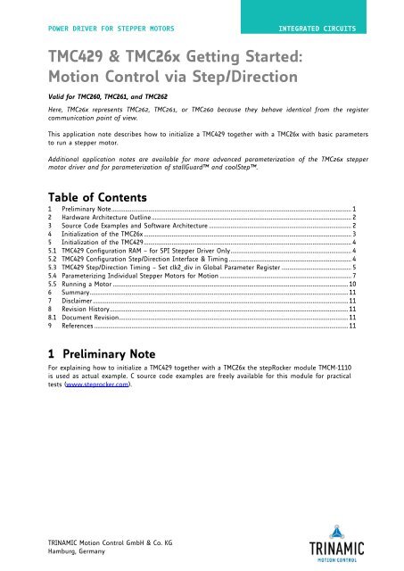
TMC429 & TMC26x Getting Started: Motion Control via ... - Trinamic
TMC429 & TMC26x Getting Started: Motion Control via ... - Trinamic
TMC429 & TMC26x Getting Started: Motion Control via ... - Trinamic

Create successful ePaper yourself
Turn your PDF publications into a flip-book with our unique Google optimized e-Paper software.
POWER DRIVER FOR STEPPER MOTORS INTEGRATED CIRCUITS<br />
<strong>TMC429</strong> & <strong>TMC26x</strong> <strong>Getting</strong> <strong>Started</strong>:<br />
<strong>Motion</strong> <strong>Control</strong> <strong>via</strong> Step/Direction<br />
Valid for TMC260, TMC261, and TMC262<br />
Here, <strong>TMC26x</strong> represents TMC262, TMC261, or TMC260 because they behave identical from the register<br />
communication point of view.<br />
This application note describes how to initialize a <strong>TMC429</strong> together with a <strong>TMC26x</strong> with basic parameters<br />
to run a stepper motor.<br />
Additional application notes are available for more advanced parameterization of the <strong>TMC26x</strong> stepper<br />
motor driver and for parameterization of stallGuard and coolStep.<br />
Table of Contents<br />
1 Preliminary Note ........................................................................................................................................................... 1<br />
2 Hardware Architecture Outline ................................................................................................................................. 2<br />
3 Source Code Examples and Software Architecture ............................................................................................ 2<br />
4 Initialization of the <strong>TMC26x</strong> ...................................................................................................................................... 3<br />
5 Initialization of the <strong>TMC429</strong> ...................................................................................................................................... 4<br />
5.1 <strong>TMC429</strong> Configuration RAM – for SPI Stepper Driver Only .............................................................................. 4<br />
5.2 <strong>TMC429</strong> Configuration Step/Direction Interface & Timing ............................................................................... 4<br />
5.3 <strong>TMC429</strong> Step/Direction Timing – Set clk2_div in Global Parameter Register ............................................. 5<br />
5.4 Parameterizing Individual Stepper Motors for <strong>Motion</strong> ..................................................................................... 7<br />
5.5 Running a Motor ........................................................................................................................................................ 10<br />
6 Summary ....................................................................................................................................................................... 11<br />
7 Disclaimer ..................................................................................................................................................................... 11<br />
8 Revision History .......................................................................................................................................................... 11<br />
8.1 Document Revision .................................................................................................................................................... 11<br />
9 References .................................................................................................................................................................... 11<br />
1 Preliminary Note<br />
For explaining how to initialize a <strong>TMC429</strong> together with a <strong>TMC26x</strong> the stepRocker module TMCM-1110<br />
is used as actual example. C source code examples are freely available for this module for practical<br />
tests (www.steprocker.com).<br />
TRINAMIC <strong>Motion</strong> <strong>Control</strong> GmbH & Co. KG<br />
Hamburg, Germany
Application Note 016 (V1.00 / 2012-MAR-26) 2<br />
2 Hardware Architecture Outline<br />
From the configuration point of view, the <strong>TMC429</strong> and TMC262 of the stepRocker have the<br />
architecture outlined in Figure 1. The motion control of the TMC262 takes place <strong>via</strong> step/direction by<br />
the <strong>TMC429</strong>. Both, the <strong>TMC429</strong> and the TMC262 are parameterized <strong>via</strong> SPI by the microcontroller.<br />
CLK_TMC<br />
MISO_1<br />
MOSI_1<br />
SCK_1<br />
nSCS_429<br />
CSN_262<br />
www.trinamic.com<br />
CLK<br />
SDOZ_C<br />
SDI_C<br />
SCK_C<br />
nSCS_C<br />
<strong>TMC429</strong><br />
nSCS2_S3<br />
nSCS3_D3<br />
nSCS_S_S2<br />
SDI_S_D2<br />
SDO_S_S1<br />
SCK_S_D1<br />
Figure 1 SPI and step/dir wiring scheme for <strong>TMC429</strong> with TMC262 on stepRocker module<br />
3 Source Code Examples and Software Architecture<br />
The complete firmware of the stepRocker (www.steprocker.com) is available as C source code<br />
example on www.trinamic.com from the stepRocker page <strong>via</strong> a link to stepRocker open TMCL<br />
Library (github).<br />
STP<br />
DIR<br />
SDO<br />
SDI<br />
SCK<br />
CSn<br />
TMC262<br />
The main program is stepRocker.c calling all necessary initializations.<br />
Please refer the HTML documentation generated from source code with doxygen concerning details<br />
of firmware architecture source code.
Application Note 016 (V1.00 / 2012-MAR-26) 3<br />
4 Initialization of the <strong>TMC26x</strong><br />
For configuration, the <strong>TMC26x</strong> has five control registers: DRVCTRL (Driver <strong>Control</strong>), CHOPCONF<br />
(Chopper Configuration), SMARTEN (Smart Energy), SGCSCONF (stallGuard2, Current Scale), and<br />
DRVCONF (driver configurations).<br />
Note: - Smart Energy is an early term for coolStep.<br />
- An application note concerning optimal chopper configuration is available. For getting<br />
started a default configuration as given here is sufficient to start a motor running.<br />
- An application note concerning the parameterization of stallGuard2 and coolStep is also<br />
available. For getting started the stallGuard2 and coolStep features will not be used. This<br />
is proposed to be done later.<br />
LIST OF IMPORTANT CONTROL REGISTERS:<br />
DRVCTRL: driver control parameter, here SDOFF=0 (default) step-direction = ON<br />
CHOPCONF: chopper configuration register<br />
SMARTEN: coolStep. Leave untouched for getting started<br />
SGCSCONF: stallGuard2. Ignored for getting started, but setting current scale is required<br />
DRVCONF: basic driver configurations switches<br />
TMC26X REGISTER CONFIGURATION EXAMPLE<br />
Register/<br />
Bit<br />
www.trinamic.com<br />
DRVCTRL<br />
(SDOFF=1)<br />
DRVCTRL<br />
(SDOFF=0)<br />
CHOPCONF<br />
SMARTEN<br />
SGCSCONF DRVCONF<br />
19 0 0 1 1 1 1<br />
18 0 0 0 0 1 1<br />
17 PHA - 0 1 0 1<br />
16 CA7 - TBL1=1 0 SFILT=1 TST=0<br />
15 CA6 - TBL0=0 SEIMIN=0 - SLPH1=1<br />
14 CA5 - CHM=0 SEDN1=0 SGT6=0 SLPH0=1<br />
13 CA4 - RNDTF=0 SEDN0=0 SGT5=0 SLPL1=1<br />
12 CA3 - HDEC1=0 - SGT4=0 SLPL0=1<br />
11 CA2 - HDEC0=0 SEMAX3=0 SGT3=0 -<br />
10 CA1 - HEND3=0 SEMAX2=0 SGT2=1 DISS2G=0<br />
9 CA0 INTPOL=0 HEND2=0 SEMAX1=0 SGT1=0 TS2G1=0<br />
8 PHB DEDGE=0 HEND1=1 SEMAX0=0 SGT0=1 TS2G0=0<br />
7 CB7 - HEND0=0 - - SDOFF=0<br />
6 CB6 - HSTRT2=0 SEUP1=0 - VSENSE=1<br />
5 CB5 - HSTRT1=1 SEUP0=0 - RDSEL1=0<br />
4 CB4 - HSTRT0=1 - CS4=0 RDSEL0=0<br />
3 CB3 MRES3=0 TOFF3=0 SEMIN3=0 CS3=0 -<br />
2 CB2 MRES2=0 TOFF2=0 SEMIN2=0 CS2=1 -<br />
1 CB1 MRES1=0 TOFF1=0 SEMIN1=0 CS1=0 -<br />
0 CB0 MRES0=0 TOFF0=1 SEMIN0=0 CS0=1 -<br />
Table 4.1 <strong>TMC26x</strong> register configuration table example<br />
SPI DATAGRAMS TO WRITE THE TMC26X REGISTER CONFIGURATION GIVEN IN THE EXAMPLE<br />
DRVCTRL = 0x00000; // set interpolation = OFF, micro step resolution = 256x<br />
CHOPCONF = 0x90131; // set TBL=3, CHM=0, RNDTF=0, TOFF=1<br />
SMARTEN = 0xA0000; // disable smart energy function (coolStep)<br />
SGCSCONF = 0xD0505; // set CS=0x05 that is 0x5/0x1F = 5/31 = 16% of max. current<br />
DRVCONF = 0xEF040; // set driver configuration & step/direction control<br />
The initialization of the driver is handled by the routine <strong>TMC26x</strong>.c: void InitMotorDrivers(void);<br />
Within the C source code example, the <strong>TMC26x</strong> control bits are stored within a data record that<br />
holds all control bits. The access is handled in a way that one can read back the actual settings from<br />
that data record. This is because the <strong>TMC26x</strong> allows reading back status information but written<br />
configuration bits are write only and cannot be read back.
Application Note 016 (V1.00 / 2012-MAR-26) 4<br />
5 Initialization of the <strong>TMC429</strong><br />
5.1 <strong>TMC429</strong> Configuration RAM – for SPI Stepper Driver Only<br />
This application note describes how to control a <strong>TMC26x</strong> <strong>via</strong> step-direction signals. For step/direction<br />
control the <strong>TMC429</strong> configuration RAM is unused and the internal sine wave look-up table (SinLUT)<br />
of the <strong>TMC26x</strong> driver is used instead. So, there is no need for initialization of the <strong>TMC429</strong><br />
configuration RAM.<br />
5.2 <strong>TMC429</strong> Configuration Step/Direction Interface & Timing<br />
ACTIVATING THE STEP/DIRECTION INTERFACE<br />
The step/direction interface of the <strong>TMC429</strong> is activated by setting the ENable StepDirection control bit<br />
EN_SD = 1 of the <strong>TMC429</strong> configuration register named if_configuration_429.<br />
TIMING OF THE STEP/DIRECTION INTERFACE<br />
The timing of the step/direction interface of the <strong>TMC429</strong> is programmed <strong>via</strong> the nibble clk2_div [3…<br />
0]. This are the bits [11… 9] of the stepper motor global parameter register.<br />
The programming of the timing is intended for use of external step/direction power stages. For local<br />
communication the timing needs to be programmed to the fastest setting that is clk2_div = 0000.<br />
5.2.1 if_configuration_429 (JDX=%0100) and Step/Direction Timing <strong>via</strong><br />
CLK2_DIV<br />
The register if_configuration_429 is the interface configuration register for the <strong>TMC429</strong>. This register<br />
is used for<br />
- configuration of the additional reference inputs,<br />
- de-multiplexed interrupt output,<br />
- step/direction interface, and for<br />
- association of the position compare output signal to one stepper motor.<br />
Register/ Bit if_configuration_429 Function<br />
8 INV_REF = 0 Invert polarity of reference switches (common polarity for<br />
all reference switches.<br />
7 SDO_INT = 1 Map internal non-multiplexed interrupt status to<br />
nINT_SDO_C (needs SDOZ_C as SDO_C for read back<br />
information from the <strong>TMC429</strong> to the micro controller); with<br />
SDO_INT='1' the nINT_SDO_C is a non-multiplexed nINT<br />
output to the micro controller<br />
6 STEP_HALT = 0 Toggle on each step pulse (this halfs the step frequency,<br />
both pulse edges represent steps); this function can be used<br />
for the TMC262; STEP_HALF reduces the required step pulse<br />
bandwidth and is use full if one used e.g. low-bandwidth<br />
opto-couples;<br />
5 INV_STP = 0 Invert step pulse polarity; this is for adaption of the step<br />
polarity to external diver stages<br />
4 INV_DIR = 0 Invert step pulse polarity; this is for adaption to external<br />
diver stages; alternatively, this can be used as a shaft bit to<br />
adjust the direction of motion for a motor, but do not use<br />
this as a direction bit because it has no effect on the<br />
internal handling of signs (x_actual, v_actual, …)<br />
3 EN_SD = 1 ENable StepDirection. Important Hint: The Step Pulse Timing<br />
(length) must be compatible with step frequency; the Step<br />
Pulse Timing is determined by the 4 LSBs of CLK2_DIV for<br />
when step/direction mode is selected by ED_SD='1';<br />
www.trinamic.com
Application Note 016 (V1.00 / 2012-MAR-26) 5<br />
Register/ Bit if_configuration_429 Function<br />
2 POS_COMP_SEL_0 = 0 Select one motor out of three motors (%00, %01, %10) for<br />
1 POS_COMP_SEL_0 = 0 the position compare function output of the <strong>TMC429</strong> named<br />
poscmp.<br />
0 EN_REFR = 1 Enable new <strong>TMC429</strong> reference inputs REFR1, REFR2, REFR3.<br />
EN_REFR=0 is the default. This is important because the<br />
REFRx input have internal pull-up resistors and this might<br />
cause trouble if these in-out are not-connected (for the<br />
SSOP16 these REFRx cannot be connected).<br />
Table 5.1 Example of if_configuration_429 interface configuration register setting for <strong>TMC429</strong><br />
SPI DATAGRAMS TO WRITE THE TMC26X REGISTER CONFIGURATION GIVEN IN THE EXAMPLE:<br />
if_configuration_429 = 0x68000089; // write JDX=4 with SDO_INT=1, EN_SD=1, EN_REFR=1<br />
The initialization of the <strong>TMC429</strong> is handled by the routine <strong>TMC429</strong>.c : void Init429(void);<br />
5.3 <strong>TMC429</strong> Step/Direction Timing – Set clk2_div in Global<br />
Parameter Register<br />
The step/direction mode is enabled while the ENable StepDirection control bit EN_SD of the<br />
if_configuration_429 register is set to 1.<br />
The timing of the step/direction interface is controlled by the four LSBs [3… 0] of the clk2_div of the<br />
global parameter register.<br />
The clk2_div [3… 0] is named stpdiv_429. For a given clock frequency fCLK [unit: MHz] of the <strong>TMC429</strong>,<br />
the length tSTEP [unit: µs] of a step pulse is<br />
tSTEP [µs] = 16 * ( 1 + stpdiv_429 ) / fCLK [MHz].<br />
For a clock frequency fCLK [MHz] of 16MHz the step pulse length can be programmed by stpdiv_429<br />
in integer multiple of 1 µs.<br />
The stpdiv_429 must be set that it is compatible to the upper step frequency fSTEP = 1 / tSTEP that<br />
is used.<br />
The first step pulse after a change of direction is delayed by tDIR2STP that is equal to tSTEP to avoid<br />
setup time violations of the step/direction power stage.<br />
Note:<br />
- The maximum step pulse frequency is fSTEP_MAX [MHz] = fCLK [MHz] / 32.<br />
- For a clock frequency fCLK [MHz] = 16MHz the maximal possible step pulse frequency fSTEP_MAX is<br />
500kHz.<br />
- For a clock frequency fCLK [MHz] = 32MHz the maximal step pulse frequency fSTEP_MAX is 1MHz.<br />
DIR<br />
STP<br />
www.trinamic.com<br />
tDIR2STP = tSTEP<br />
tSTEP<br />
tDIR2STP = tSTEP<br />
tSTEP<br />
Figure 2: <strong>TMC429</strong> Step/direction timing (EN_SD='1' & STEP_HALF='0')
Application Note 016 (V1.00 / 2012-MAR-26) 6<br />
For SD_EN = 1 the clk2_div [3… 0] is named stpdiv_429 within the <strong>TMC429</strong> datasheet (available on<br />
www.trinamic.com). In step/direction mode the other control bits of the stepper motor global<br />
parameter register are ignored. For setting the fastest step/direction timing write 0 in the stepper<br />
motor global parameter register with<br />
stepper_motor_global_parameter_register = 0x7E000000; // clk2_div = O resp. stpdiv_429 = 0<br />
This initialization of the <strong>TMC429</strong> is also handled by the routine <strong>TMC429</strong>.c : void Init429(void);<br />
Generally:<br />
For short wire link between <strong>TMC429</strong> and <strong>TMC26x</strong> of the step/direction signals (e.g. on TMCM-1110<br />
stepRocker board) one can set the shortest tSTEP be setting stpdiv_429 = 0.<br />
EXCERPT OF STEPPER MOTOR GLOBAL PARAMETER REGISTER<br />
Register/ Bit<br />
www.trinamic.com<br />
Stepper motor global<br />
parameter register<br />
Function<br />
23<br />
22<br />
21 mot1r For SD_EN = 1 of in if_configuration_429 this control bit<br />
is ignored.<br />
20 refmux For SD_EN = 1 of in if_configuration_429 this control bit<br />
is ignored.<br />
19<br />
18<br />
17<br />
16<br />
15<br />
14<br />
13<br />
12<br />
11<br />
10<br />
9<br />
8<br />
7<br />
6<br />
5<br />
4<br />
3<br />
2<br />
1<br />
0<br />
continuous_update<br />
clk2_div [7…4]<br />
clk2_div [3…0] = 0<br />
csCommonIndividual<br />
polarities<br />
LSDM = 00, 01, 10<br />
For SD_EN = 1 of in if_configuration_429 this control bit<br />
is ignored.<br />
For SD_EN = 1 of in if_configuration_429 this part of the<br />
register is ignored.<br />
For SD_EN = 1 of in if_configuration_429 this defines the<br />
timing of the step/direction interface; setting to O for<br />
fastest timing.<br />
For SD_EN=1 of in if_configuration_429 this part of the<br />
register is ignored<br />
Polarities of the SPI signals for the SPI stepper motor<br />
driver chain.<br />
Not relevant for step/direction mode of <strong>TMC429</strong><br />
Last stepper motor driver.<br />
Not relevant for step/direction mode of <strong>TMC429</strong><br />
Table 5.2 Example of stepper motor global parameter register for <strong>TMC429</strong> step/direction timing
Application Note 016 (V1.00 / 2012-MAR-26) 7<br />
5.4 Parameterizing Individual Stepper Motors for <strong>Motion</strong><br />
The preceding basic initializations of interfacing normally need to be done only once. Now, proceed<br />
as follows:<br />
- Choose and set the motion parameters v_min and v_max.<br />
- Choose and set the clock pre-dividers pulse_div and ramp_div.<br />
- Choose and set the microstep resolution usrs.<br />
- Set a_max with a valid pair of pmul and pdiv.<br />
- Choose the switch configuration ref_conf with the ramp mode rm.<br />
- Pull down to ground or disable the reference switch inputs REF1, REF2, REF3 plus REF1R,<br />
REF2R, and REF3R by setting ref_conf.<br />
5.4.1 Choose x_target (for Ramp Mode) or v_target (for Velocity<br />
Mode)<br />
With the above mentioned settings the <strong>TMC429</strong> runs a motor if one writes either x_target or<br />
v_target, depending on the choice of the ramp mode rm.<br />
Each stepper motor has its associated set of registers for motion control. Before running a motor,<br />
parameters have to be initialized. For many applications there is no need to re-program settings<br />
done once during initialization.<br />
MODES OF OPERATION:<br />
The parameters mentioned here allow the adjustment for a wide range of applications.<br />
- For ramp_mode the microcontroller sends desired target positions x_target and the <strong>TMC429</strong><br />
autonomously takes care of positioning.<br />
- For velocity_mode, the micro controller sends the desired target velocity v_target to the<br />
<strong>TMC429</strong> to run a stepper motor continuously with that speed.<br />
All motion control parameters are represented as integer resp. signed integer values within units<br />
that are specific for the <strong>TMC429</strong> (depending on the clock frequency used for the <strong>TMC429</strong>).<br />
5.4.2 Real World Units, Units of Stepper Motors, and <strong>TMC429</strong> Internal<br />
Units<br />
From the stepper motor application point of view, motion control parameters within units of<br />
fullsteps (FS) for position, fullsteps per second (FS/s) for velocity, and fullsteps per second square<br />
(FS/s^2) for acceleration are natural units for stepper motors. The formulas to calculate into these<br />
units are given in the <strong>TMC429</strong> datasheet section pulse_div & ramp_div & usrs (IDX=%1100).<br />
The following calculation files are available on www.trinamic.com (on <strong>TMC429</strong> product page):<br />
- tmc429_frequencies.xls spread sheet, which calculates between physical motion units (rad, rad/s…)<br />
and stepper specific units (FS, FS/s, …)* 1<br />
- <strong>TMC429</strong>Calc.exe standalone program* 2<br />
* 1 The link between real world units and stepper motor units in full step units is an application specific gear ration that<br />
defines how distances (in meters, inches…) or angels (radians, grad…) match with one full step.<br />
* 2 The link between time in seconds and <strong>TMC429</strong> units is done <strong>via</strong> lengths of internal counter and the clock frequency fCLK<br />
[MHz] of the <strong>TMC429</strong>.<br />
www.trinamic.com
Application Note 016 (V1.00 / 2012-MAR-26) 8<br />
5.4.3 Velocity R [Hz] and Acceleration R [Hz/s]<br />
The desired microstep frequency R [Hz] and the desired microstep acceleration R [Hz] depend on<br />
the application. Typical stepper motors can go up to fullstep frequencies of some thousand fullsteps<br />
per second. Without load, they can accelerate to those fullstep frequencies within a couple of<br />
fullsteps.<br />
5.4.3.1 Choosing Microstep Resolution / Step Pulse Pre-Divider / Acceleration<br />
Pre-Divider<br />
Microstep resolution, step pulse pre-divider, and acceleration pre-divider have to be set according to<br />
the following procedure.<br />
1. CHOOSE THE MICROSTEP RESOLUTION<br />
First, set a microstep resolution. It is assumed that the highest microstep resolution usrs = 6 for the<br />
driver motion control of the SPI driver chain is set. In step/direction mode the microstep resolution<br />
is controlled within the driver chip and should be taken into account.<br />
2. SET THE STEP PULSE PRE-DIVIDER<br />
Then, the pulse pre-divider has to be determined. It allows scaling the step frequencies in a very<br />
wide range. Therefore take into account the maximum desired velocity v_max. Based on the formula<br />
R [Hz] = f_clk [Hz] * velocity / ( 2^pulse_div * 2048 * 32 ) given within the <strong>TMC429</strong> datasheet one can<br />
determine<br />
pulse_div := log( f_clk [Hz] * v_max / ( R [Hz] * 2048 * 32 ) ) / log(2)<br />
setting v_max = 2047 (or 2048 for simplified calculation) and R [Hz] to the maximum desired<br />
microstep frequency.<br />
The fullstep frequency can be calculated based on the formula R FS [Hz] = R [Hz] / 2^usrs given within<br />
the <strong>TMC429</strong> data sheet. With this, the microstep frequency is R [Hz] = R FS [Hz] * 2^usrs. The quotient<br />
of logarithms comes from the relation log 2(x) = log(x) / log(2) to calculate the logarithm to the basis<br />
of two which is the number of bits need to represent x. The calculation result of pulse_div then has<br />
to be chosen close to the next integer value.<br />
Hint:<br />
For step/direction control <strong>via</strong> <strong>TMC429</strong>, the microstep frequency R [Hz] of the <strong>TMC429</strong> is relevant. For<br />
calculation of full step frequency the microstep resolution of the <strong>TMC26x</strong> is relevant. This is because<br />
each step pulse of the <strong>TMC429</strong> is a microstep for the <strong>TMC26x</strong>.<br />
3. SET THE RAMP PRE-DIVIDER<br />
After determination of pulse_div, the parameter ramp_div can be calculated. Based on the formula<br />
R[Hz/s] = f_clk[Hz] * f_clk[Hz] * a_max / ( 2^(pulse_div+ramp_div+29) ) given within the <strong>TMC429</strong><br />
datasheet one can determine<br />
ramp_div := log( f_clk [Hz] * f_clk [Hz] * a_max / ( R [Hz/s] * 2^(pulse_div+29) ) ) / log(2)<br />
setting a_max = 2047 (or 2048 for simplified calculation) and R [Hz/s] to the maximum desired<br />
microstep acceleration. The calculation result of ramp_div then has to be chosen close to the next<br />
integer value.<br />
www.trinamic.com
Application Note 016 (V1.00 / 2012-MAR-26) 9<br />
5.4.3.2 Choosing Step Velocities v_min and v_max and the Step Acceleration<br />
a_max<br />
The v_min parameter should be set to 1 (please refer the <strong>TMC429</strong> datasheet for details).<br />
The v_max parameter determines the maximum velocity and has to be set depending on the<br />
application.<br />
The change of the parameter a_max requires a recalculation of p_mul and p_div. Once set, the<br />
a_max parameter can be left untouched for many applications.<br />
Hints for a_max setting:<br />
If the parameters pulse_div and ramp_div are equal, the parameter a_max can be set to any value<br />
within the range of 0 … 2047.<br />
If the parameters pulse_div and ramp_div differ, the limits a_max_lower_limit and<br />
a_max_upper_limit have to be checked (please refer to the <strong>TMC429</strong> datasheet).<br />
The velocity does not change with a_max = 0.<br />
5.4.3.3 Calculate p_mul and p_div for a Chosen Set of Parameters<br />
The two parameters p_mul and p_div have to be calculated for positioning in RAMP_MODE. These<br />
parameters depend on pulse_div, ramp_div, and a_max. The parameters p_mul and p_div have to<br />
be recalculated if one of the parameters pulse_div, ramp_div, a_max changes.<br />
An example for calculation of p_mul and p_div for the <strong>TMC429</strong> is given as a C program included<br />
within the <strong>TMC429</strong> datasheet. This C program source code can be copied directly out of the PDF<br />
document. Additionally, a spread sheet named tmc429_pmulpdiv.xls demonstrating the calculation<br />
of pmul and pdiv is available on www.trinamic.com for download.<br />
The principle of calculation of p_mul and p_div is simple: the routine CalcPMulPDiv(...) gets the<br />
parameters a_max, ramp_div, pulse_div, with a reduction factor p_reduction. With these parameters,<br />
a pmul is calculated for any allowed p_div ranging from 0 to 13. The p_div, which results in a valid<br />
pmul that is in the range of 0 to 127 (resp. p_mul that is in range 128… 255) selects a valid pair of<br />
p_mul and p_div.<br />
p_mul and p_div have to be determined for each set of pulse_div, ramp_div, and a_max.<br />
www.trinamic.com
Application Note 016 (V1.00 / 2012-MAR-26) 10<br />
5.4.4 Set the Reference Switch Configuration and the Ramp Mode<br />
Both, the reference switch configuration (ref_conf) and the ramp mode (rm) are configured by access<br />
to a single register. Normally, this kind of initialization is done only once. Please proceed as follows:<br />
- Choose the switch configuration ref_conf together with the ramp mode rm.<br />
- Pull unused reference switch inputs REF1, REF2, REF3 down to ground or disable them by<br />
setting ref_conf. (Otherwise, the REF1, REF2, and REF3 inputs might detect a switch signal<br />
and stop a motor.)<br />
The most important register part (except reference switch configuration) is the rm for setting<br />
RAMP_MODE for positioning applications or VELOCITY_MODE for constant speed applications.<br />
Register/<br />
Bit<br />
www.trinamic.com<br />
Stepper motor global<br />
parameter register<br />
Function<br />
23<br />
22<br />
21<br />
20<br />
19<br />
18<br />
17<br />
16<br />
15<br />
14<br />
13<br />
12<br />
LP Latched position waiting (read only status bit)<br />
11<br />
REF_RnL = 0<br />
Reference switch right not left (to change assignment of<br />
left/right switch)<br />
10<br />
SOFT_STOP = 1<br />
Soft stop with deceleration a_max during for active stop<br />
switch<br />
9 DISABLE_STOP_R = 1 Disable stop switch right.<br />
8<br />
7<br />
6<br />
5<br />
4<br />
3<br />
2<br />
DISABLE_STOP_L = 1 Disable stop switch left.<br />
1<br />
0<br />
RM = %00, %01, %10, %11<br />
Ramp mode: 00 = RAMP_MODE, 01 = SOFT_MODE,<br />
10 = VELOCITY_MODE, 11 = HOLD_MODE<br />
Table 5.3 Example of REF_CONF and RAMP_MODE setting for stepper motor #O (smda = %00)<br />
5.5 Running a Motor<br />
All necessary settings for getting started are done now. Run your stepper motor as follows:<br />
RAMP_MODE: write the desired target position into the register x_target of the associated<br />
motor.<br />
VELOCITY_MODE: write the desired target velocity v_target of the associated motor.
Application Note 016 (V1.00 / 2012-MAR-26) 11<br />
6 Summary<br />
This application note explains how to initialize a <strong>TMC429</strong> motion controller and a <strong>TMC26x</strong> stepper<br />
motor driver. The initialization of the <strong>TMC429</strong> is done <strong>via</strong> a sequence of a couple of SPI datagrams.<br />
The initialization of the stepper motor driver <strong>TMC26x</strong> is done by up to five SPI datagrams. So,<br />
altogether the initialization is represented by a sequence of a couple of SPI datagrams. After<br />
initialization, motion commands can simply be executed by writing motion parameters (target<br />
positions, target velocities…) into <strong>TMC429</strong> registers by sending SPI datagrams.<br />
Based on the low cost motion controller/driver board TMCM-1110 stepRocker, this application note<br />
shows with a practical example – available as C open source code - how to get a stepper motor<br />
running. The sample C code is intended to be used as a basis for own developments of customers.<br />
7 Disclaimer<br />
TRINAMIC <strong>Motion</strong> <strong>Control</strong> GmbH & Co. KG does not authorize or warrant any of its products for use<br />
in life support systems, without the specific written consent of TRINAMIC <strong>Motion</strong> <strong>Control</strong> GmbH &<br />
Co. KG. Life support systems are equipment intended to support or sustain life, and whose failure to<br />
perform, when properly used in accordance with instructions provided, can be reasonably expected<br />
to result in personal injury or death.<br />
Information given in this application note is believed to be accurate and reliable. However no<br />
responsibility is assumed for the consequences of its use nor for any infringement of patents or<br />
other rights of third parties which may result from its use.<br />
Specifications are subject to change without notice.<br />
All trademarks used are property of their respective owners.<br />
8 Revision History<br />
8.1 Document Revision<br />
Version Date Author<br />
LL – Lars Larsson<br />
SD – Sonja Dwersteg<br />
www.trinamic.com<br />
Description<br />
1.00 2012-FEB-03 LL Initial version<br />
1.01 2012-MAR-26 SD New design<br />
9 References<br />
- TMC260/TMC261/TMC262 datasheet, www.trinamic.com<br />
- <strong>TMC429</strong> datasheet, www.trinamic.com<br />
- stepRocker (TMCM-1110) Hardware Manual, www.trinamic.com<br />
- stepRocker (TMCM-1110) <strong>Getting</strong> <strong>Started</strong> (www.trinamic.com)<br />
- stepRocker (TMCM-1110) Schematic (www.trinamic.com)<br />
- Open Source <strong>Motion</strong> <strong>Control</strong> Community<br />
- www.motioncontrol-community.org or www.steprocker.com