Electrical Grounding Group (CADWELD)
Electrical Grounding Group (CADWELD)
Electrical Grounding Group (CADWELD)

You also want an ePaper? Increase the reach of your titles
YUMPU automatically turns print PDFs into web optimized ePapers that Google loves.
<strong>Grounding</strong> & Bonding<br />
The Foundation For Effective <strong>Electrical</strong> Protection<br />
January 24, 2006<br />
Tuesday 2:15-3:00 PM<br />
Curtis R. Stidham<br />
Harger Lightning & <strong>Grounding</strong>
Objectives<br />
• Define the difference between grounding & bonding and to<br />
describe the roles they play in providing protection for<br />
personnel and equipment.<br />
• Define the role of grounding & bonding as the key element<br />
for an effective electrical protection and power quality<br />
system.<br />
• Present the different types of equipment & products used to<br />
implement an effective grounding and bonding system.
Outline<br />
• <strong>Grounding</strong> & Bonding<br />
– What is <strong>Grounding</strong> & Bonding?<br />
– Why do we Ground?<br />
– Different types of Ground Systems<br />
– Hazards & Safety<br />
– Relevant Standards<br />
• Ground Electrode System<br />
– What makes up the system?<br />
– Results from NFPA - NEGRP<br />
– Connections (Critical Element)
Outline<br />
• <strong>Grounding</strong> and Bonding Applications<br />
– Power Systems<br />
– Lightning Protection<br />
– Computer Installations
Foundation of Protection<br />
Lightning<br />
Protection<br />
Surge<br />
Suppression<br />
Bonding<br />
<strong>Grounding</strong>
Key to Systems Approach<br />
• Protection systems are not independent.<br />
• Lightning Protection and Surge Suppression Systems rely on a good<br />
grounding & proper bonding for effective performance.<br />
• <strong>Grounding</strong> & bonding are not always well understood in their application.<br />
• Improper grounding & bonding is commonly the root cause of Power<br />
Quality Problems.
Risks of Not Providing Protection<br />
• Human safety<br />
• Equipment damage<br />
• Downtime and loss of operations<br />
• Customer dissatisfaction about reliability<br />
• Loss of revenue and service
What is <strong>Grounding</strong>?<br />
• Definition: (IEEE 100)<br />
A conducting connection, whether intentional or<br />
accidental, by which an electric circuit or<br />
equipment is connected to the Earth, or to some<br />
conducting body of relatively large extent that<br />
serves in place of the Earth.
What is <strong>Grounding</strong>?<br />
• Purpose:<br />
– Used for establishing and maintaining the<br />
potential of the Earth or approximately that<br />
potential, on conductors connected to it.<br />
– Conduct ground current to and from the Earth.
Why Ground?<br />
Required by CODE (NFPA 70 - NEC Article 250)<br />
• The National <strong>Electrical</strong> Code, NFPA-70, addresses<br />
proper electrical systems and equipment installation<br />
to protect people and property from hazards arising<br />
from the use of electricity in buildings and structures.
Why Ground?<br />
Personnel Safety<br />
Reduce Potential Differences<br />
Between enclosures<br />
Between enclosures and Earth
Why Ground? Personnel Safety<br />
Current Ranges<br />
• 1-6 mA, (often referred to as let-go currents)<br />
– unpleasant<br />
– Does not impair control of muscles<br />
• 9-25 mA<br />
– may be painful<br />
– difficult or impossible to release energized objects grasped by the hand<br />
• 60-100 mA<br />
– ventricular fibrillation<br />
– stoppage of the heart<br />
– inhibition of respiration might occur
Why Ground? Personnel Safety<br />
ANSI/IEEE Std. 80-2000<br />
• Step Potential: Difference in surface potential<br />
experienced by a person’s feet bridging a<br />
distance of 1m without contacting any other<br />
grounded surface.<br />
• Touch Potential: Potential difference between<br />
GPR and the surface potential at the point<br />
where a person is standing, while at the same<br />
time having hands in contact with a grounded<br />
structure.<br />
MOST DANGEROUS
Why Ground? Personnel Safety<br />
• Step Potential: Controlled by<br />
properly designed ground electrode<br />
system (grid) or the use of wire mesh.<br />
• Touch Potential: Controlled by<br />
proper bonding and protective<br />
systems such as personnel safety<br />
mats.<br />
Bonding Conductor<br />
Safety Mat<br />
Flexible Braid<br />
Switch Handle Bond
Why Ground?<br />
• Equipment Protection<br />
– Operate over-current devices during a ground fault.<br />
– Provide over-voltage control.
Why Ground?<br />
• Lightning Protection Systems (Dissipate Energy)<br />
NFPA 780
Why Ground?<br />
• ESD (Electrostatic Discharge)
Why Ground?<br />
• Signal Reference <strong>Grounding</strong> – Noise Control<br />
IEEE Std 1100 (Emerald Book)<br />
Powering and <strong>Grounding</strong> Electronic Equipment
Summary:<br />
Why Ground?<br />
• Human Safety<br />
• Protect Equipment<br />
• Lightning Protection<br />
• Electrostatic Discharge<br />
• Signal Reference <strong>Grounding</strong>
Relevant Standards & Codes<br />
• NFPA 70 National Electric Code<br />
• IEEE Std C2 National Electric Safety Code<br />
• NFPA 780 Standard for the Installation of Lightning Protection Systems<br />
• ANSI/J-STD-607-A-2002 Commercial Building <strong>Grounding</strong> (Earthing) and<br />
Bonding Requirements for Telecommunications<br />
• ANSI T1.313-2003 <strong>Electrical</strong> Protection for Telecommunications Central<br />
Offices and Similar Type Facilities
Relevant Standards & Codes<br />
• IEEE Std 80 Guide for Safety in AC Substation <strong>Grounding</strong><br />
• IEEE Std 142 (Green Book): Recommended Practice for<br />
<strong>Grounding</strong> of Industrial and Commercial Power Systems<br />
• IEEE Std 602 (White Book): Recommended Practice for<br />
Electric Systems in Health Care Facilities<br />
• IEEE Std 1100 (Emerald Book): Recommended Practice for<br />
Powering and <strong>Grounding</strong> Electronic Equipment
Equipment <strong>Grounding</strong><br />
• Purpose:<br />
• Provide Personnel Safety<br />
• Means:<br />
• Interconnecting all non-current carrying metal<br />
components to eliminate potential differences between<br />
them. (raceways, cabinets, frames, cable armor,<br />
building steel, etc…)<br />
• Connecting the equipment grounding conductor to<br />
Earth will eliminate potential differences between metal<br />
components and Earth.
Equipment <strong>Grounding</strong><br />
(Personnel Safety)
System <strong>Grounding</strong><br />
• Purpose:<br />
• Provide equipment protection by operating over-current<br />
devices to clear fault current and providing a potential<br />
reference.<br />
• Means:<br />
• An intentional connection to equipment ground from<br />
one of the current carrying conductors of an electrical<br />
distribution system.
System <strong>Grounding</strong><br />
(Equipment Protection)
Effective <strong>Grounding</strong> Path<br />
NEC 250<br />
• The path to ground from circuits, equipment, and metal<br />
enclosures for conductors shall (1) be permanent and electrically<br />
continuous, (2) have capacity to conduct safely any fault current<br />
likely to be imposed on it, and (3) have sufficiently low<br />
impedance to limit voltage to ground and to facilitate the<br />
operation of the circuit protective devices.<br />
• The Earth shall not be used as the sole equipment grounding<br />
conductor.
Earth as Equipment <strong>Grounding</strong> Electrode<br />
Unacceptable / Code Violation
What is Bonding?<br />
• Definition: (NEC 250)<br />
The permanent joining of metallic parts to form an<br />
electrically conductive path that will assure<br />
electrical continuity and the capacity to conduct<br />
safely any current likely to be imposed.
Bonding<br />
• Interconnect ALL Ground Electrode Systems<br />
– <strong>Electrical</strong> <strong>Grounding</strong> System<br />
– Lightning <strong>Grounding</strong> System<br />
– Telecommunications <strong>Grounding</strong> System<br />
– Cable <strong>Grounding</strong> System<br />
• Interconnect ALL conductive objects together both internal<br />
and external to the facility<br />
• Provides near zero voltage difference during GPR
Bonding<br />
• Poor bonding is often the principle cause of many<br />
hazardous and noise-producing situations.<br />
• Leading to:<br />
– Unacceptable Voltage Drops<br />
– Heat Generation<br />
– Intermittent Operation<br />
– <strong>Electrical</strong> Noise<br />
– High Resistance Grounds
Bonding Components:<br />
• Conductors<br />
• Connectors/Clamps/Lugs<br />
• Ground Bars
Bonding Components:<br />
• Equipment Ground Plates<br />
• Fence Clamps and Gate Jumpers<br />
• Equipotential Mesh and Mats
Bonding Components:<br />
• Signal Reference Grids<br />
• Coaxial Ground Kits
Ground Electrode System<br />
• Soil<br />
• Ground Electrode Conductors<br />
• Connectors<br />
• Electrodes
Soils<br />
• Soil Resistivity - Some soils, (such as sandy soils), have such high<br />
resistivities that conventional ground rods or ground electrode systems<br />
may be unable to attain the desired ground resistance requirement.<br />
Enhanced ground electrodes or ground enhancement materials may be<br />
required to meet the grounding specification.<br />
• Soil PH/type - PH a factor in choosing. Some ground rod types work<br />
better in different soils.<br />
• Soil Characteristics - Some sites may have only a few inches of soil (or<br />
none) sitting on top of bedrock. In this case, ground mesh is the preferred<br />
electrode. (Never drill into bedrock).
Soil Conditions<br />
• Soil Resistivity Must Be Carefully Considered, Including<br />
Moisture Content and Temperature.
<strong>Grounding</strong> Electrode System<br />
NEC 250.52<br />
Formed by bonding all of the following:<br />
• Metal underground water pipe (soil contact at least 10’)<br />
• Building steel<br />
• Concrete encased electrode (Ufer Ground)<br />
• Ground ring<br />
• Made and other electrodes<br />
• Local underground systems or structures, piping, tanks, well<br />
casings<br />
• Rod & Pipe electrodes<br />
• Plates electrodes
Ground Electrodes<br />
• Electrodes must be of proper material and cross section to<br />
provide a low impedance path to fault current without fusing.<br />
• Many Types of Electrodes are Available<br />
• Driven Ground Rods<br />
• Pole Butt Plates (Distribution Poles)<br />
• Ground Plates<br />
• Counterpoise Wires<br />
• Foundations (UFER GROUNDS)<br />
• Electrolytic (Enhanced) Ground Rods
NEC 250: Resistance of Made Electrode<br />
• Single Electrode<br />
– R = 25 ohms or less<br />
– R > 25 ohm, a second electrode is installed<br />
• Electrodes at least 6 feet apart
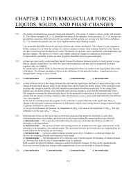
Electrode Considerations Cont..<br />
Ground Rod Diameter - Doubling<br />
diameter reduces resistance only 10%.<br />
Ground Rod Length - Doubling length<br />
reduces resistance 40%, actual<br />
reduction depends on soil resistivities<br />
encountered in multi-layered soils.<br />
Ground Rod Spacing - Approximately<br />
twice the length. (in good soil).<br />
RESISTANCE, %<br />
RESISTANCE, OHMS<br />
600<br />
500<br />
400<br />
300<br />
200<br />
100<br />
120%<br />
100%<br />
0<br />
80%<br />
60%<br />
40%<br />
20%<br />
RESISTANCE VS ROD DIAMETER<br />
RESISTANCE %<br />
0%<br />
0.500 0.625 0.750 0.875 1.000 1.125 1.250 1.375 1.500<br />
ROD DIAMETER, INCHES<br />
RESISTANCE VS ROD DEPTH<br />
5 10 15 20 25 30 35 40 45 50 55 60 65 70 75 80 85 90 95 100<br />
ROD DEPTH, FT<br />
1/2 ROD OHMS<br />
1" ROD OHMS
Ground Rod Spacing<br />
¾” x 10’ Rod<br />
• One Ground Rod<br />
R = 32 Ω<br />
ρ= 100 Ωm<br />
• Two Ground Rods<br />
• Spacing = 20’<br />
R = 17.4 Ω
Electrode Considerations<br />
Ufer Grounds - Concrete encased electrode.<br />
For example, tying into the tower footing<br />
rebar or building pad rebar provides a Ufer<br />
ground. Ufer grounds should never be used<br />
as the sole ground electrode.<br />
Copper Ground Mesh - Used to augment the<br />
grounding system. The mesh can be<br />
strategically placed to protect personnel<br />
against step and touch potentials.
Conductive Backfill<br />
Vertical Application Horizontal Application
Enhanced Ground Rods<br />
Contain electrolytic salts that lower soil resistivity over time
Galvanized Ground Rod (5/8”x10’)<br />
NFPA - NEGRP Pawnee Site<br />
10 years in the ground
Copper Clad Steel Ground Rod (5/8”x8’)<br />
NFPA - NEGRP Pawnee Site<br />
10 years in the ground
Horizontal Cu-Clad Steel Ground Rod in GEM ®<br />
NFPA - NEGRP Pawnee Site<br />
• This electrode (5/8”x8’) and the connections were completely enclosed in GEM.<br />
• The 1’ long bent portion of the ground rod was completely corroded away up to<br />
the exothermic connection. The remaining ½” long portion of the ground rod and<br />
the exothermic weld was connected with less than one strand of wire.<br />
• The mechanical connection was also very corroded.<br />
• Only small sections of the rod were found within the GEM due to significant<br />
corrosion of the ground rod.
Leads<br />
Bent Portion of<br />
Rod Missing<br />
Only Copper<br />
Coating Remains<br />
at this Point<br />
Remaining<br />
Portion of Rod<br />
Horizontal Cu-Clad Steel Ground Rod in GEM ®<br />
NFPA - NEGRP Pawnee Site<br />
10 years in the ground
Horizontal Cu-Clad Steel Ground Rod in GEM®<br />
NFPA - NEGRP Pawnee Site
Ground Conductor Considerations<br />
Sizing - withstand maximum fault current for the maximum clearing time.<br />
Inductance - Flat strap conductors have less inductance than their<br />
similarly sized round conductor counterparts.<br />
Strength/Durability - Round conductors are much stronger than thin flat<br />
strap conductor. This should be a consideration when backfilling<br />
trenches.<br />
Exothermic Connections - Preferred type of connection.
Effect of Inductance<br />
For 1 meter of 4/0 conductor:<br />
L = 1.02 µH R = 0.16<br />
mW<br />
Voltage Rise:<br />
dI<br />
V = ( L × ) + ( R × I )<br />
dt<br />
R L<br />
Conductor Model<br />
For a strike of Imax = 18,000 A in 1µsec<br />
−6<br />
18000<br />
−3<br />
V = ( 1.<br />
02 × 10 × ) + ( 0.<br />
16 × 10 × 18000)<br />
−6<br />
1×<br />
10<br />
= 18,360 + 3 Volts/meter of conductor<br />
Inductive Term Greatly Dominates Resistive Term
Connectors<br />
• Connections must be of proper material and mass, and be<br />
able to resist corrosion to maintain original low resistance<br />
for the life of the system.<br />
• Types<br />
• Exothermic<br />
• Mechanical<br />
• Compression
What is Lightning?<br />
Consider Lightning a Gigantic <strong>Electrical</strong> Spark traveling between Cloud to Cloud<br />
or Cloud to Earth containing an average Charge of 30 to 50 Million Million<br />
Volts and a<br />
Current of 18,000 Amps.
Basic Principles of Lightning Protection<br />
• Intercept the Lightning Discharge<br />
• Safely Conduct the Lightning Currents<br />
• Minimize the Effects of Lightning Currents<br />
• Dissipate the Lightning Currents in the Earth
Lightning Surface Arcing
NFPA 780 Lightning Protection Standard<br />
• Scope - This document shall<br />
cover traditional lightning<br />
protection system installation<br />
requirements for ordinary<br />
structures, misc. structures,<br />
special occupancies, etc.
Risks Posed from a Direct Strike
Risks Posed from an Indirect Strike
Basic LP Components<br />
• Air Terminals<br />
• Lightning Conductors<br />
• Ground Terminals<br />
• Connectors/Fittings<br />
• Surge Suppression Devices
Lightning Characteristics<br />
Lightning - High frequency (approx. 1 megahertz) electrical<br />
discharge carrying on average 18,000 amps and 30 million<br />
volts. Time duration of event is measured in microseconds.<br />
Lightning Conductors - Multiple, parallel low<br />
impedance paths sufficient enough to carry lightning<br />
currents safely to ground terminal system. Minimum<br />
standard requirements set by UL96A & NFPA 780.<br />
* Due to its high frequency & voltage, lightning does not<br />
like to stay on one conductor. Therefore, multiple parallel<br />
paths are critical!!!
Characteristics of Electricity<br />
Electricity - low frequency (60 Hz) low voltage (
In other words…..<br />
A lightning ground does not equal a “green wire” ground!!!!!
Lightning<br />
• Lightning Travels on the outside surface of a conductor, the<br />
so called “skin affect”. Therefore, the larger the surface area<br />
of a conductor and not necessarily the cross sectional area, the<br />
better path it makes.<br />
• Remember, multiple parallel paths are very important. The<br />
fewer paths you have the larger the surface area or diameter<br />
the conductor needs to have.
Lightning Conductor Types<br />
Solid conductors -<br />
Difficult to work with<br />
Concentric strand - Next<br />
easiest to work with<br />
Rope Lay LP - Easiest to<br />
work with<br />
Flat strap - least<br />
inductance; hardest to<br />
work with
Lightning Conductor Routing & Placement<br />
General rules of Thumb for Routing:<br />
• Maintain downward sloping path to ground<br />
(equipotential bonds exception)<br />
• Do not run conductors uphill (1/4 rise<br />
acceptable to a point)<br />
• Maintain at least an 8” radius of bend
To Comm.<br />
Equipment<br />
Drain Pipe<br />
Ground<br />
From<br />
Antenna<br />
• Uphill path to<br />
ground<br />
• Radius of bend less<br />
than 8”<br />
• Bonding issue<br />
• Water pipe?
Lightning Surface Arcing
Lightning Ground Systems<br />
• Provide multiple ground paths for lightning energy<br />
• Radials effectively lower impedance (R & X L)<br />
• Divert lightning energy away from equipment shelter<br />
• Maximum Radial Length of 90’ for Lightning Effectiveness<br />
• Use Radials of different lengths
Computer Installations<br />
<strong>Grounding</strong> System – Four<br />
Distinct Subsystems<br />
• NEC Compliant Fault/Personnel<br />
Protection Power System Ground<br />
(including surge suppression)<br />
• Lightning Protection subsystem<br />
(per NFPA 780)<br />
• Telecom, data transmission, and signaling circuit surge protection<br />
grounding subsystem.<br />
• Signal Reference Structure
High Frequency <strong>Grounding</strong> System<br />
• Reduces or eliminates high<br />
frequency transients by<br />
achieving a common ground<br />
reference for all equipment<br />
within a contiguous area.<br />
• Consists of a Signal Reference<br />
Grid, low-impedance bonding<br />
straps, transient suppression<br />
plates and bare copper bonding<br />
conductors.
Why a High Frequency <strong>Grounding</strong> System?<br />
• Most computer systems today run on<br />
roughly a 3 volt operating system. A<br />
transient of just one volt can cause<br />
serious data errors. (Transient Over-<br />
Voltages).<br />
• It is imperative to tie all equipment<br />
together with a low impedance<br />
“signal reference” bonding system to<br />
keep any voltage differences at a<br />
minimum.
Sources of Transient Over-voltages<br />
• Lightning Induced Surges<br />
• Power Systems Operations<br />
• Power System Faults<br />
• Reactive Load Switching<br />
• Harmonics<br />
• Ground Potential Rise
Transients May be Induced onto:<br />
• Power Lines<br />
• Telephone Lines<br />
• Data Signaling Lines<br />
• RF Feeders<br />
• Building Structural Members (lightning)<br />
• Differential Grounds
Signal Reference Grid (SRG)<br />
• Function: Minimize voltage differences between<br />
interconnected equipment by providing a low<br />
impedance equipotential ground plane for high<br />
frequency low voltage noise.
SRG Types<br />
• Round Conductor<br />
– Easier to install when retrofitting an<br />
existing raised floor system.<br />
• Flat Strip<br />
– Superior system. (Less impedance than<br />
round conductors; very important at<br />
high frequencies).<br />
– Less labor to install.
<strong>Grounding</strong> & Bonding<br />
The Foundation For Effective <strong>Electrical</strong> Protection<br />
January 24, 2006<br />
Tuesday 2:15-3:00 PM<br />
Curtis R. Stidham<br />
Harger Lightning & <strong>Grounding</strong>