
You also want an ePaper? Increase the reach of your titles
YUMPU automatically turns print PDFs into web optimized ePapers that Google loves.
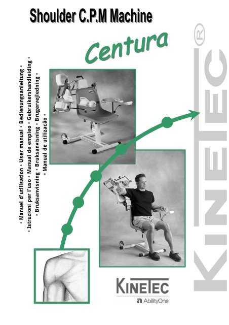
• <strong>Manuel</strong> d’utilisation • User manual • Bedienungsanleitung •<br />
• Istruzioni per l’uso • Manual de empleo • Gebruikershandleiding •<br />
• Bruksanvisning • Bruksanvisning • Brugervejledning •<br />
• Manual de utilização •
• <strong>Manuel</strong> d’utilisation • EPAULE<br />
Avant toute utilisation lire ce document.<br />
AbilityOne Kinetec se réserve le droit de toutes modifications techniques.<br />
• User manual • SHOULDER<br />
Before use, please read this document.<br />
AbilityOne Kinetec reserves the right to effect technical modifications.<br />
• Bedienungsanleitung • SCHULTER<br />
Vor Benutzung unbedingt dieses Dokument lesen.<br />
AbilityOne Kinetec behält sich das Recht vor, jegliche technische Änderung durchzuführen.<br />
• Istruzioni per l’uso • SPALLA<br />
Prima di mettere in funzione l’apparecchio leggere con attenzione il presente documento.<br />
La AbilityOne Kinetec si riserva il diritto di apportare modifiche tecniche.<br />
• Manual de empleo • HOMBRO<br />
Antes de cualquier utilización, lea este documento.<br />
AbilityOne Kinetec se reserva el derecho a cualquier modificación técnica.<br />
• Gebruikershandleiding • SCHOUDER<br />
Lees voor ieder gebruik dit document door.<br />
AbilityOne behouden zich het recht voor technische wijzigingen aan te brengen<br />
• Bruksanvisning • SHULDRA<br />
Läs denna bruksanvisning noga innan Du använder apparaten.<br />
AbilityOne Kinetec förbehåller sig rätten att göra tekniska ändringar på produkten.<br />
• Bruksanvisning • SKULDER<br />
Les denne bruksanvisningen før du tar apparatet i bruk.<br />
AbilityOne forbeholder seg retten til å foreta tekniske modifikasjoner.<br />
• Brugervejledning • SKULDER<br />
Inden ibrugtagning skal denne vejledning læses igennem.<br />
AbilityOne Kinetec forbeholder sig ret til tekniske ændringer.<br />
• Manual de utilização • ESPADUA<br />
Recomenda-se a leitura deste documento antes de iniciar a utilização do aparelho.<br />
AbilityOne Kinetec reserva-se o direito a quaisquer alterações técnicas.<br />
F<br />
G<br />
B<br />
D<br />
I<br />
E<br />
N<br />
L<br />
S<br />
N<br />
D<br />
K<br />
P<br />
G<br />
R
SUMMARY<br />
Page 1<br />
Page<br />
DESCRIPTION 2-6<br />
ASSEMBLY & TRANSPORT 7<br />
USE OF THE HAND CONTROL 8-18<br />
INSTRUCTIONS FOR USE 19-31<br />
ACCESSORIES 32<br />
PRODUCT INFORMATION 33-35<br />
SAFETY RECOMMENDATIONS<br />
• Before use, please read this document.<br />
• The physician defines the protocol and ensures that it is correctly implemented<br />
(adjustments, session durations and frequency of use).<br />
• We recommend that you lock the hand control when you give it to the patient.<br />
• For optimum safety, always give the hand control to the patient before starting the<br />
system.<br />
• Explosion hazard: KINETEC Centura is not designed for use in the presence of<br />
flammable anesthetics.<br />
• Check that the electrical socket is in good condition and is suitable for the splint power<br />
supply cord. The latter complies with current standards and has a grounding socket.<br />
The plug may be connected to any standard socket. The socket must however have a<br />
grounded pin.<br />
To connect the power supply, only use the original cable supplied with the machine.<br />
Check that the cables remain free around the device so that they do not get damaged.<br />
Manual N°: 467896270 – Updated July 2003<br />
KINETEC Centura – Series 2-3<br />
KINETEC and Centura are trademark of AbilityOne.<br />
Select your language<br />
SEE PAGE 36<br />
GB
GB<br />
DESCRIPTION<br />
DEFINITION<br />
The KINETEC Centura is a upper extremity PASSIVE mobilization device enabling<br />
the following movements:<br />
• Extension 20° Flexion 180°.<br />
• Adduction 20° Abduction 160°.<br />
• Internal Rotation 60° External Rotation 90°.<br />
• Synchronized Abduction + Rotation<br />
Adduction 20° Abduction 160°.<br />
Internal Rotation 30° External Rotation 90°.<br />
• Horizontal Abduction from –30° to 110° (available on Centura 5)<br />
• Indications<br />
• Total shoulder replacement.<br />
• Repeated dislocation of the humerus.<br />
• Rotator cuff injury.<br />
• Upper humerus fractures<br />
• Scapula fractures.<br />
• Acromioplasty.<br />
• Capsulotomy.<br />
• Arthrolysis.<br />
• Synovectomy for Rheumatoid Arthritis.<br />
• All type of shoulder styffness joint.<br />
• Clinical Benefits<br />
• Breaks the cycle of trauma, inflammation and the loss of range of motion.<br />
• Prevents joint stiffness.<br />
• Speeds the recovery of post-operative range of motion.<br />
• Maintains the quality of the articular surface.<br />
• Reduces pain and edema.<br />
• Promotes articular cartilage healing.<br />
• Reduces hospitalization time<br />
• Reduces the need for pain medication.<br />
• Contraindications<br />
- Unstable fractures.<br />
- Spastic paralyses.<br />
- Uncontrolled infection.<br />
- The machine are not adapted for patients height more 2m(6’7”) or under 1.4m(4’7”)<br />
Page 2
DESCRIPTION<br />
ELECTRICAL CONNECTION<br />
KINETEC Centura is a type B class I device.<br />
Before connecting the device to the power supply, check<br />
that the mains voltage matches that shown on the plate<br />
(100-240 V~ / 50-60 Hz) below switch ON (2).<br />
Connect the power supply cable (1).<br />
IMPORTANT<br />
Check that the electrical socket is in good condition and is suitable for the splint power supply<br />
cord. The latter complies with current standards and has a grounding socket. The plug may be<br />
connected to any standard socket. The socket must however have a grounded pin.<br />
To connect the power supply, only use the original cable supplied with the machine.<br />
Check that the cables remain free around the device so that they do not get damaged.<br />
The cables (motors and hand control) can be plugged in<br />
any of the connectors<br />
Starting the unit<br />
Switch on (2).<br />
While the unit begins an auto diagnostic, the display shows the following:<br />
Your KINETEC Centura is ready to be used.<br />
SAFETY<br />
KINETEC<br />
CENTURA V3.2<br />
MOVEMENT VERIF.<br />
MOToR : M1 M2<br />
The physician defines the protocol and ensures that it is correctly implemented (adjustments, session<br />
durations and frequency of use).<br />
The patient must know the start/stop/reverse function on the control handle. Hand control must be<br />
accessible to patient at all times.See page 8.<br />
KINETEC Centura complies with Directive 93/42/CEE.<br />
EXPLOSION HAZARD:<br />
KINETEC Centura is not designed for use in the presence of flammable<br />
anesthetics.<br />
In case of electromagnetic interference with other devices move the device.<br />
KINETEC Centura is in compliance with standards in force (IEC 601.1.2),<br />
electromagnetic compatibity standard for medical devices.<br />
Page 3<br />
3<br />
2<br />
1<br />
MOVEMENT VERIF.<br />
Please wait<br />
FLEX/EXT<br />
50 STOP 15 100<br />
GB
GB<br />
DESCRIPTION<br />
13<br />
DESCRIPTION • COMPONENTS<br />
KINETEC Centura consists of the following components:<br />
1 – Chair<br />
2 – Frame<br />
3 – Wheels<br />
4 – Transport handle<br />
5 – Arm rest knobs<br />
6 – Arm rest<br />
7 – Hand control support<br />
11<br />
10<br />
12<br />
8<br />
9<br />
Page 4<br />
7<br />
5<br />
4<br />
6<br />
1<br />
2<br />
8 – Locking of the right/left sliding<br />
9 – Locking of the up/down sliding<br />
10 – Chair locking knob<br />
11 – Locking of the abduction<br />
motor<br />
12 – Abduction motor<br />
13 – Shoulder depth sliding lock<br />
3
30<br />
32<br />
20<br />
31<br />
DESCRIPTION<br />
21<br />
15<br />
22<br />
25<br />
33<br />
Abduction associated with rotation splint<br />
19<br />
14<br />
16 17<br />
18<br />
Abduction or flexion splint<br />
23<br />
Page 5<br />
14 – Arm length setting lock<br />
15 – 90° elbow splint<br />
16 – 90°elbow splint lock<br />
17 – Rotation motor<br />
18 – Rotation motor lock<br />
19 – Forearm length setting lock<br />
20 – Forearm slider<br />
21 – Right/left bean swivel lock<br />
22 – Forearm splint<br />
18 – Swiveling splint support lock<br />
23 – Swiveling splint support<br />
24 – Elbow flexion setting lock<br />
25 – Arm splint<br />
26 – Arm splint lock<br />
27 – Forearm length setting lock<br />
Horizontal Abduction splint (available on Centura 5)<br />
34<br />
26<br />
18<br />
24<br />
27<br />
29<br />
28<br />
28 – Horizontal abduction column<br />
29 – Arm length setting lock<br />
30 – Elbow splint support lock<br />
31 – Elbow support older<br />
32 – 90°elbow splint lock<br />
33 – Forearm length setting lock<br />
34 – Forearm slider<br />
GB
GB<br />
DESCRIPTION<br />
14<br />
16<br />
17<br />
20<br />
21<br />
DESCRIPTION • ELECTRICAL<br />
1 – Supply cable connector switch<br />
2 – Fuse<br />
3 – ON/OFF switch<br />
4 – Hand control lock switch<br />
5 – Defect or power light<br />
6 – Motor or hand control connectors<br />
7 – Hand control location for transport<br />
8 – Hand control<br />
24<br />
10 11 12 13<br />
9<br />
15<br />
18<br />
23<br />
19<br />
22<br />
Page 6<br />
4<br />
6<br />
7<br />
8<br />
9 – Liquid-crystal display<br />
10 – Flexion/extension<br />
11 – Abduction/adduction<br />
12 – Rotation<br />
13 – Abduction/adduction synchronized with rotation<br />
14 – Lower limits setting<br />
15 – Upper limits setting<br />
16 – Increase / decrease<br />
17 – START<br />
18 – STOP<br />
19 – FORCE<br />
20 – SPEED<br />
21 – PAUSE<br />
22 – TIMER<br />
23 – PROGRAM access<br />
24 – Horizontal abduction<br />
5<br />
2<br />
3<br />
1
ASSEMBLY & TRANSPORT<br />
Base assembly<br />
2<br />
Remove all the components from their packaging.<br />
Unscrew the chair locking knob (3).<br />
Position the chair (1) on the base (2) with the back of the chair at the wheel and<br />
screw the chair locking knob (3) to secure it in place.<br />
Place the Abduction motor (4) on right or left, depending on the limb be moved.<br />
3<br />
The other components to be used depend on the selected movement.<br />
Unit transport<br />
For easy transport of the unit, it features 2 wheels (5) and a handle (6).<br />
Place the arm support as close as possible<br />
to the chair to limit the overall dimensions<br />
and help balance the unit.<br />
Place your foot as indicated to balance the<br />
unit.<br />
You can adjust the height of the handle with<br />
knob (7).<br />
1<br />
2<br />
Page 7<br />
3<br />
5<br />
4<br />
6<br />
7<br />
GB
GB<br />
USE OF THE HAND CONTROL<br />
Locking the hand control setting<br />
The hand control allows the patient to control the<br />
machine as appropriate.<br />
The switch (4) has 3 positions:<br />
LOCKED POSITION<br />
The operational settings can be read and the<br />
START/STOP/REVERSE function operated.<br />
UNLOCKED POSITION<br />
All adjustments are possible.<br />
HALF-LOCKED POSITION<br />
It is possible to switch the program and modify the upper and lower movement<br />
limits. The START/STOP/REVERSE function is always accessible.<br />
Double locking<br />
Simultaneously press the and keys to lock the hand control.<br />
The display reads LOCK. To unlock the hand control, simultaneously press the same keys.<br />
The displays reads UNLOCK.<br />
You can not change the parameters, if you try the display reads: LOCK<br />
We recommend that you lock the hand control<br />
when you give it to the patient.<br />
START/STOP/REVERSE function<br />
As with all KINETEC systems, KINETEC Centura is equipped with a<br />
START/STOP/REVERSE function.<br />
When the unit is running, the display reads RUN<br />
Press the key of the hand control. The movement stops.<br />
The display reads STOP<br />
Press the key of the hand control. The movement starts<br />
in the opposite direction and the display reads RUN.<br />
Caution:<br />
For optimum safety, always give the hand control to the patient before starting<br />
the system.<br />
Page 8<br />
4
USE OF THE HAND CONTROL<br />
Reset time function<br />
This function allows one to read the running time since the last resetting of the counter.<br />
Beginning<br />
To stop the unit<br />
Press simultaneously on the<br />
2 keys<br />
To reset the counter, press<br />
the key<br />
Or<br />
After 5 seconds, the reset<br />
function switches off and the<br />
running time remains in the<br />
memory.<br />
Keys to<br />
press<br />
How to choose a movement<br />
Page 9<br />
Display Remarks<br />
First switch the machine off and put the switch in the or<br />
position in order to change the movement.<br />
Check if the locking switch is<br />
in the following position<br />
or<br />
The display indicates the<br />
running time since the last<br />
resetting.<br />
The counter is now reset.<br />
You can select a movement by pressing the appropriate button. The LED is on.<br />
When a movement is first selected, the system returns to the original<br />
parameters of the movement (default settings).<br />
Default settings:<br />
Abduction Flexion/Extension Rotation<br />
Abduction +<br />
Rotation<br />
Horizontal*<br />
abduction<br />
• Lower limit 30° 30° 0° 30° 0° -30°<br />
• Upper limit 90° 100° 60° 100° 60° 60°<br />
• Speed 2 2 2 2 2<br />
• Load 6 6 6 6 6<br />
• Extension pause 0 0 0 0 0<br />
• Flexion pause 0 0 0 0 0<br />
• Timer 0 0 0 0 0<br />
Possible values for each parameter:<br />
FLEX/EXT<br />
50 STOP 15 100<br />
RESET TIME 125H<br />
Reset: limit low<br />
RESET TIME 125H<br />
Reset is done<br />
FLEX/EXT<br />
50 STOP 15 100<br />
Abduction Flexion/Extension Rotation Abduction + Rotation<br />
• Lower limit 20° to 155° 20° to 175°<br />
-60° to 85°<br />
extern<br />
20° to<br />
155°<br />
• Upper limit 25° to 160° 25° to 180°<br />
-55°to 90°<br />
extern<br />
25° to<br />
160°<br />
• Speed 1 to 5 (from 50° to 140° per minute)<br />
• Load 1 to 6<br />
• Extension pause 0 to 900 seconds (15 minutes)<br />
• Flexion pause 0 to 900 seconds (15 minutes)<br />
• Timer<br />
* Available on Centura 5 or in option.<br />
No time (00H00) to 24H00<br />
-30° to 85°<br />
extern<br />
-25° to 90°<br />
extern<br />
Horizontal<br />
abduction*<br />
-30° to 105°<br />
-25° to 110°<br />
GB
GB<br />
USE OF THE HAND CONTROL<br />
How to adjust the parameters of single movements<br />
Beginning<br />
To stop the unit<br />
To choose the movement<br />
Or<br />
Or<br />
Or<br />
To display the lower limit<br />
of the movement<br />
To change the lower limit<br />
if necessary<br />
To validate the new value,<br />
press another key<br />
or wait more than 3<br />
seconds<br />
Or to display pause<br />
To change pause value in<br />
upper limit of movement if<br />
necessary<br />
To validate and display<br />
the pause value in lower<br />
limit of movement<br />
To change the pause<br />
value in lower limit of<br />
movement if necessary<br />
To validate the new value<br />
press another key<br />
or wait more than 3 seconds.<br />
The display shows the<br />
selected movement.<br />
Keys to<br />
press<br />
Page 10<br />
Display Remarks<br />
Check if the locking switch<br />
is in the following<br />
position:<br />
The display shows the<br />
new movement selected<br />
and the default settings of<br />
the upper and lower limits<br />
of this movement.<br />
The display shows “not available”<br />
if you d’ont have the horizontal<br />
abduction module.<br />
The value blinks.<br />
or The new value blinks.<br />
Or<br />
Or<br />
ROTATION<br />
0 STOP 0 60<br />
Abd/add<br />
30 STOP 90 90<br />
Rotation<br />
0 STOP 0 60<br />
FLEX/EXT<br />
30 STOP 89 100<br />
ABD HOR<br />
30 STOP 50 60<br />
FLEX/EXT<br />
30 STOP 89 100<br />
FLEX/EXT<br />
50 STOP 89 100<br />
FLEX/EXT<br />
50 STOP 89 100<br />
FLEX/EXT<br />
NO TIMER<br />
FLEX/EXT<br />
SPEED 02<br />
FLEX/EXT<br />
LOAD : _ _ _ _<br />
FLEX/EXT<br />
PAUSE HIGH 0S<br />
FLEX/EXT<br />
PAUSE HIGH 10S<br />
FLEX/EXT<br />
PAUSE LOW 0S<br />
FLEX/EXT<br />
PAUSE LOW 10S<br />
FLEX/EXT<br />
30 STOP 89 100<br />
While the value blinks<br />
press<br />
the or key<br />
to change if necessary.<br />
The pause value in upper<br />
limit of movement blinks.<br />
The new pause value in<br />
upper limit of movement<br />
blinks.<br />
The pause value in lower<br />
limit of movement blinks.<br />
The new pause value in<br />
lower limit of movement<br />
blinks.<br />
The unit is ready to start<br />
with the new parameters.
USE OF THE HAND CONTROL<br />
How to set the synchronized movement parameters<br />
Beginning<br />
To stop the unit<br />
To select the combined<br />
movement<br />
To press a second time on<br />
the key<br />
Keys to<br />
press<br />
Page 11<br />
Display Remarks<br />
Synchronization rules:<br />
• The degress of rotation are lower than or equal to the degrees of abduction.<br />
• 1° of abduction means 1° of rotation.<br />
Check if the locking switch<br />
is in the following<br />
position:<br />
The indication “ABD”<br />
blinks and the display<br />
shows the values for the<br />
abduction movement.<br />
To change it, proceed as<br />
for a single movement.<br />
The indication “ROT”<br />
blinks and the display<br />
shows the values for the<br />
rotation movement.<br />
To change it, proceed as<br />
for a single movement.<br />
• When the degrees of rotation are lower than the degrees of abduction, the synchronization<br />
applies to the upper degrees of the movement.<br />
Example : abduction from 30° to 100°<br />
rotation from 50° to 90°<br />
FLEX/EXT<br />
50 STOP 15 100<br />
SYNC ABD/ROT<br />
30 STOP 15 100<br />
SYNC ABD/ROT<br />
0 STOP 0 60<br />
Comments:<br />
• Speed, load, pauses and timer are the same for both of the movement components. The<br />
setting is the same as for a single movement.<br />
• Pauses can be set at the lower and/or the upper limits of the abduction movement.<br />
• You will have successive displays of abduction movement limits, or associated rotation<br />
movement, by repeatedly pressing the synchronized movement button.<br />
• You cannot change the settings while the machine is running.<br />
GB
GB<br />
USE OF THE HAND CONTROL<br />
Using Programs<br />
The KINETEC Centura allows you to store up to 16 programs, including the type of<br />
movement, ROM, speed, load, pauses and timer.<br />
The original parameter values of the program are empty.<br />
These values can be modified and recorded at any time (see ‘How to enter a<br />
program’ p 14).<br />
To select a program:<br />
Beginning<br />
To stop the unit<br />
To access the program<br />
mode<br />
To change the program if<br />
necessary<br />
To exit and validate the<br />
selected program<br />
To exit without validation<br />
of selected program<br />
Start the unit<br />
Keys to<br />
press<br />
or<br />
Page 12<br />
Display Remarks<br />
FLEX/ext<br />
30 STOP 89 100<br />
PROGRAM 1<br />
EMPTY<br />
PROGRAM 3<br />
0 ROTATION 90<br />
ROTATION<br />
0 STOP 0 60<br />
FLEX/ext<br />
30 STOP 89 100<br />
FLEX/EXT<br />
30 RUN 89 100<br />
Check if the locking switch<br />
is in the following position:<br />
or<br />
The program number<br />
blinks.<br />
The new program number<br />
blinks.<br />
The current parameters<br />
have been recorded in<br />
program 3.<br />
Back to the starting<br />
parameters.<br />
The value change at the<br />
speed of the movement.<br />
Comments:<br />
• The values show in the ‘Display’ column are examples. They actually depend on<br />
the stored programs.<br />
• The current movement parameters can be changed while using that program but<br />
no data will be stored in the original program. See the programming mode (p 14) to<br />
modify programs.
USE OF THE HAND CONTROL<br />
Reading the values of a program: example SPEED<br />
Beginning<br />
To stop the unit<br />
To access the program<br />
mode<br />
To change the program if<br />
necessary<br />
To read the speed value<br />
After 15 seconds or after<br />
pressing on another key<br />
To exit and validate the<br />
selected program<br />
Start the unit<br />
Comments:<br />
Keys to<br />
press<br />
or<br />
Page 13<br />
Display Remarks<br />
ROTATION<br />
0 STOP 0 90<br />
PROGRAM 1<br />
0 ROTATION 30<br />
PROGRAM 3<br />
0 ROTATION 90<br />
PROGRAM 3<br />
SPEED 5<br />
PROGRAM 3<br />
0 ROTATION 90<br />
ROTATION<br />
0 STOP 0 90<br />
ROTATION<br />
0 RUN 0 90<br />
Check if the locking switch<br />
is in the following position:<br />
or<br />
The program number<br />
blinks.<br />
The new program number<br />
blinks.<br />
Displaying the speed<br />
value.<br />
The current parameters<br />
have been recorded in<br />
program 3.<br />
The value change at the<br />
speed of the movement.<br />
• The values showed in the ‘Display’ column are examples. They actually depend on<br />
the stored programs.<br />
• The current movement parameters can be changed while using that program but<br />
no data will be stored in the original program. See the programming mode (p 14) to<br />
modify programs.<br />
GB
GB<br />
USE OF THE HAND CONTROL<br />
How to modify programs PROGRAM MODE:<br />
Beginning<br />
To switch off the unit<br />
To press the two keys at<br />
the same time to switch<br />
the unit on<br />
Then<br />
To change the program if<br />
necessary<br />
To choose the movement<br />
Or<br />
Or<br />
Or<br />
Or<br />
To display the lower limit<br />
of the movement<br />
To change the lower limit<br />
of the movement if<br />
necessary<br />
To validate the new value,<br />
press another key<br />
Or display pauses<br />
To change pause value in<br />
upper limit of movement if<br />
necessary<br />
Keys to<br />
press<br />
or<br />
Page 14<br />
Display Remarks<br />
Check if the locking switch<br />
is in the following<br />
position:<br />
Welcome text during 3<br />
seconds.<br />
The program number<br />
blinks.<br />
The new program number<br />
blinks.<br />
The display indicates the<br />
selected movement,<br />
the program number<br />
blinks again.<br />
The display shows “not available”<br />
if you d’ont have the horizontal<br />
abduction module.<br />
The value blinks.<br />
or The new value blinks.<br />
or<br />
KINETEC<br />
CENTURA V3.2<br />
PROGRAM 1<br />
EMPTY<br />
PROGRAM 10<br />
EMPTY<br />
PROGRAM 10<br />
30 ABD/ADD 90<br />
PROGRAM 10<br />
0 ROTATION 60<br />
PROGRAM 10<br />
30 FLEX/EXT 100<br />
PROGRAM 10<br />
30 SYNC ABD 100<br />
PROGRAM 10<br />
30 ABD HOR 100<br />
PROGRAM 10<br />
30 SYNC ABD 100<br />
PROGRAM 10<br />
50 SYNC ABD 100<br />
PROGRAM 10<br />
50 SYNC ABD 100<br />
PROGRAM 10<br />
TIMER 00H15<br />
PROGRAM 10<br />
SPEED : 1<br />
PROGRAM 10<br />
LOAD : _ _ _ _<br />
PROGRAM 10<br />
PAUSE HIGH 0<br />
PROGRAM 10<br />
PAUSE HIGH 10<br />
The value blinks. Press<br />
the or key<br />
to change if necessary.<br />
The pause value in upper<br />
limit of movement blinks.<br />
The new pause value in<br />
upper limit of movement<br />
blinks.
USE OF THE HAND CONTROL<br />
How to modify programs PROGRAM MODE (continued)<br />
Beginning<br />
To validate and display<br />
the pause lower limit of<br />
movement<br />
To change the pause<br />
lower limit of movement if<br />
necessary<br />
To validate and display of<br />
the combined rotation<br />
setting<br />
To change the lower limit<br />
of the movement<br />
To change the lower limit<br />
if necessary<br />
To validate and display<br />
the upper limit of the<br />
movement<br />
To change the upper limit<br />
if necessary<br />
To record the program 10<br />
Then<br />
OR<br />
To cancel the program<br />
To exit program mode,<br />
switch off and switch on<br />
the unit.<br />
Keys to<br />
press<br />
or<br />
Page 15<br />
Display Remarks<br />
The pause value in lower<br />
limit of movement blinks.<br />
The new pause value in<br />
lower limit of movement<br />
blinks.<br />
The program number<br />
blinks and the display<br />
indicates the rotation<br />
values combined with<br />
abduction.<br />
The value blinks.<br />
or The new value blinks.<br />
or<br />
PROGRAM 10<br />
PAUSE low 0<br />
PROGRAM 10<br />
PAUSE low 20<br />
PROGRAM 10<br />
0 sync rot 60<br />
PROGRAM 10<br />
0 sync rot 60<br />
PROGRAM 10<br />
10 sync rot 60<br />
PROGRAM 10<br />
10 sync rot 60<br />
PROGRAM 10<br />
10 sync rot 75<br />
PROGRAM 10<br />
Save: + clear: -<br />
PROGRAM 10<br />
SAving<br />
PROGRAM 11<br />
empty<br />
PROGRAM 10<br />
clearing<br />
PROGRAM 11<br />
empty<br />
KINETEC<br />
CENTURA V3.2<br />
The value blinks.<br />
The new value blinks.<br />
(see page 11 for more<br />
information about<br />
combined movement)<br />
The program 10 has been<br />
recorded and the display<br />
indicates the next program<br />
so you can change<br />
another program.<br />
The program 10 has been<br />
cancelled and the display<br />
indicates the next program<br />
so you can change<br />
another program.<br />
To use the modified<br />
program see page 12.<br />
GB
GB<br />
USE OF THE HAND CONTROL<br />
Timer<br />
Pause on<br />
lower limit<br />
Pause on<br />
upper limit<br />
Load<br />
Speed<br />
Upper limit<br />
Lower<br />
limit<br />
Movement<br />
type<br />
Program<br />
number<br />
Comments:<br />
• When a program has been deleted, the display shows<br />
• The values shown in the ‘Display’ column are examples. They actually depend on<br />
the stored programs.<br />
Program table:<br />
1<br />
2<br />
3<br />
4<br />
5<br />
6<br />
Page 16<br />
7<br />
8<br />
9<br />
10<br />
11<br />
PROGRAM 11<br />
EMPTY<br />
12<br />
13<br />
14<br />
15<br />
16
USE OF THE HAND CONTROL<br />
How to define the upper and lower movement limits<br />
• At the start of a session<br />
The MANUAL MODE is a way to set within the tolerance of a patient at the beginning of a session.<br />
Proceed as below:<br />
Beginning<br />
Switch the unit on<br />
To select the MANUAL<br />
MODE for upper limits by<br />
continually holding<br />
pressure on the key<br />
To set the pain level when<br />
reached, immediately<br />
press<br />
To select the manual<br />
mode for lower limits<br />
To set the pain level when<br />
reached, immediately<br />
press<br />
To start the session with<br />
the new movement limits<br />
Keys to<br />
press<br />
continuous<br />
press<br />
continuous press<br />
Page 17<br />
Display Remarks<br />
KINETEC<br />
CENTURA V3.2<br />
MOVEMENT VERIF.<br />
PLEASE WAIT<br />
MOVEMENT VERIF.<br />
MOTEoR: M1 M2<br />
FLEX/EXT<br />
50 STOP 15 100<br />
FLEX/EXT<br />
50 MANUaL 15 100<br />
FLEX/EXT<br />
50 MANUaL 150 150<br />
FLEX/EXT<br />
50 MANUaL 100 150<br />
FLEX/EXT<br />
25 MANUaL 25 150<br />
FLEX/EXT<br />
25 run 30 150<br />
Check if the locking switch<br />
is in the following<br />
position: or<br />
The unit is moving to the<br />
upper limit of the<br />
movement.<br />
The new upper value limit<br />
of the movement is<br />
recorded.<br />
The unit is moving to the<br />
lower limit of the<br />
movement<br />
The new lower value limit<br />
of the movement is<br />
recorded.<br />
The angle display<br />
changes with current<br />
movement.<br />
Specific rules for synchronized movement:<br />
• You can only change the upper limit of the movement through the manual mode and only beyond the<br />
synchronization point.<br />
Comments:<br />
• The values shown in the ‘Display’ column are examples. They actually depend on the stored<br />
programs.<br />
GB
GB<br />
USE OF THE HAND CONTROL<br />
• During the session<br />
The BY-PASS MODE is a way to record the pain threshold of a patient during a session.<br />
Beginning<br />
The unit is running<br />
To select the BY-PASS<br />
MODE<br />
To set the new pain level<br />
when reached,<br />
immediately press<br />
To select the BY-PASS<br />
mode for lower limits<br />
To set the new pain level<br />
when reached,<br />
immediately press<br />
Continue the session with<br />
the new movement limits.<br />
Keys to<br />
press<br />
continuous press<br />
continuous press<br />
Page 18<br />
Display Remarks<br />
FLEX/EXT<br />
25 RUN 30 150<br />
FLEX/EXT<br />
25 BYPASS 160 150<br />
FLEX/EXT<br />
25 BYPASS 160 160<br />
FLEX/EXT<br />
25 BYPASS 20 160<br />
FLEX/EXT<br />
20 BYPASS 20 160<br />
FLEX/EXT<br />
20 BYPASS 50 160<br />
The angle display<br />
changes with current<br />
movement.<br />
Check if the locking switch<br />
is in the following<br />
position: or<br />
The unit exceeds the<br />
recorded upper limit.<br />
The new upper value limit<br />
of the movement is<br />
recorded.<br />
The unit is moving to the<br />
lower limit of the<br />
movement.<br />
The new lower value limit<br />
of the movement is<br />
recorded.<br />
The angle display<br />
changes with current<br />
movement.<br />
Specific rules for synchronized movement:<br />
• You can only change the upper limit of the movement through the manual mode and only beyond the<br />
synchronization point.<br />
Comments:<br />
• The values shown in the ‘Display’ column are examples. They actually depend on the stored<br />
programs.
INSTRUCTIONS FOR USE<br />
How to use the pads<br />
KINETEC Centura is delivered with 7 straps:<br />
Part number to order the complete set: 4650001397<br />
All these straps are used the same way (see pictures).<br />
Do not tighten the straps too much.<br />
Page 19<br />
• 4 straps on the abduction combined with<br />
the rotation or horizontal abduction splint.<br />
• 3 straps on the abduction or flexion splint.<br />
To meet optimal hygiene, clean the straps after each patient.<br />
GB
GB<br />
INSTRUCTIONS FOR USE<br />
Adjustments for ABDUCTION/ADDUCTION<br />
with fixed EXTERNAL ROTATION<br />
The KINETEC Centura provides motion from 20° to 160° of abduction.<br />
The rotation position can be adjusted between 60° and 90°.<br />
Parts needed<br />
• Chair • Abduction rotation splint • Hand control<br />
Assembling the parts<br />
Loosen the knob (1) and slide the motor<br />
support (2) to the right or the left.<br />
Plug in the hand control.<br />
Use the color code to assemble the elbow<br />
splint (6) (red for right, blue for left). The<br />
assembly is secure when you hear a ‘click’.<br />
Assemble the abduction motor (3) and<br />
tighten the screw (4).<br />
Plug in the motor.<br />
Use the color code to assemble the forearm<br />
splint (7). Tighten the knob (8).<br />
Page 20<br />
Use the color code to assemble the<br />
rotation motor (red for right, blue for left).<br />
The assembly is secure when you hear a<br />
‘click’.<br />
Plug in the motor.<br />
The KINETEC Centura is shown assembled<br />
for a left shoulder mobilization.
INSTRUCTIONS FOR USE<br />
Patient set up<br />
Make sure the straps are clean.<br />
Put the unit in the position that is the most comfortable for the patient.<br />
Position the patient in the chair in a<br />
comfortable position and<br />
supporting the affected arm.<br />
Adjusting the shoulder joint axis<br />
c – Vertical adjustment:<br />
• Loosen the 2 knobs (1).<br />
• With the handle (2),<br />
adjust the height of the entire mechanism.<br />
• Tighten the 2 knobs (1).<br />
d – Side to side adjustment:<br />
• Loosen the knob (3)<br />
• Slide the entire mechanism<br />
• Tighten the knob (3)<br />
e – Scapula plan choice<br />
• Loosen the knob (4)<br />
• Rotate the arm support<br />
• Tighten the knob (4).<br />
• Adjust the arm rest.<br />
Starting the unit<br />
• Adjustment of the rotation position:<br />
Slide the arm supports toward<br />
the patient and put the arm in the<br />
supports.<br />
Secure pads.<br />
Page 21<br />
Adjust the lengths:<br />
a - arm<br />
b - forearm.<br />
- Press and find the right position with the MANUAL MODE (see page 17)<br />
• Choice of the abduction/adduction motion:<br />
- Press and adjust your parameters (see page 10).<br />
- Or select a program (see page 12).<br />
GB
GB<br />
INSTRUCTIONS FOR USE<br />
Adjustments for ABDUCTION/ADDUCTION<br />
with fixed ELBOW EXTENSION / FLEXION<br />
The KINETEC Centura provides motion from 20° to 160° of abduction.<br />
During this motion the elbow flexion settings are fixed.<br />
Parts needed<br />
• Chair • Abduction or flexion splint • Hand control<br />
Assembling the parts<br />
Loosen the knob (1) and slide the motor<br />
support(2) to the right or the left .<br />
Plug in the hand control.<br />
Use the color code to assemble the<br />
forearmsplint (7). Tighten the knob (6).<br />
Assemble the abduction motor (3) and<br />
tighten the screw (4).<br />
Plug in the motor.<br />
Position arm splint (8).<br />
The assembly is secure when you hear a<br />
‘click’<br />
Page 22<br />
Use the color code to assemble the<br />
forearm splint (red for right, blue for left).<br />
The assembly is secure when you hear a<br />
‘click’.<br />
The KINETEC Centura is shown assembled<br />
for left shoulder mobilization.
INSTRUCTIONS FOR USE<br />
Patient set up<br />
Make sure the straps are clean.<br />
Put the unit in the position that is the most comfortable for the patient.<br />
Position the patient in the chair in a<br />
comfortable position and<br />
supporting the affected arm.<br />
Adjusting the shoulder joint axis<br />
c – Vertical adjustment:<br />
• Loosen the 2 knobs (1).<br />
• With the handle (2),<br />
adjust the height of the entire mechanism.<br />
• Tighten the 2 knobs (1).<br />
d – Side to side adjustment:<br />
• Loosen the knob (3)<br />
• Slide the entire mechanism<br />
• Tighten the knob (3)<br />
e – Scapula plan choice<br />
• Loosen the knob (4)<br />
• Rotate the arm support<br />
• Tighten the knob (4).<br />
• Adjust the arm rest.<br />
Slide the arm supports toward<br />
the patient and put the arm in the<br />
supports.<br />
Secure pads.<br />
Starting the unit<br />
• Adjustment of the elbow flexion position:<br />
- Unscrew the knob (6) and adjust the flexion as appropriate.<br />
• Choice of the abduction/adduction motion:<br />
- Press and adjust your parameters (see page 10)<br />
- Or select a program (see page 12).<br />
Page 23<br />
Adjust the lengths:<br />
a - arm<br />
b - forearm.<br />
GB
GB<br />
INSTRUCTIONS FOR USE<br />
Adjustments for ABDUCTION/ADDUCTION with<br />
ASSOCIATED ROTATION<br />
The KINETEC Centura provides motion from 20° to 160° of abduction<br />
associated with 120° of rotation in maximum.<br />
Parts needed<br />
• Chair • Abduction with associated rotation splint • Hand control<br />
Assembling the parts<br />
Loosen the knob (1) and slide the motor<br />
support (2) to the right or the left.<br />
Plug in the hand control.<br />
Use the color code to assemble the elbow<br />
splint (6). The assembly is secure when you<br />
hear a ‘click’.<br />
Assemble the abduction motor (3) and<br />
tighten the screw (4).<br />
Plug in the motor.<br />
Use the color code to assemble the forearm<br />
splint (7). Tighten the knob (8).<br />
Page 24<br />
Use the color code to assemble the<br />
rotation motor (red for right, blue for left).<br />
The assembly is secure when you hear a<br />
‘click’.<br />
Plug in the motor.<br />
The KINETEC Centura is shown assembled<br />
for left shoulder mobilization.
INSTRUCTIONS FOR USE<br />
Patient set up<br />
Make sure the straps are clean.<br />
Put the unit in the position that is the most comfortable for the patient.<br />
Position the patient in the chair in a<br />
comfortable position and<br />
supporting the affected arm.<br />
Adjusting the shoulder joint axis<br />
c – Vertical adjustment:<br />
• Loosen the 2 knobs (1).<br />
• With the handle (2),<br />
adjust the height of the entire mechanism.<br />
• Tighten the 2 knobs (1).<br />
d – Side to side adjustment:<br />
• Loosen the knob (3)<br />
• Slide the entire mechanism<br />
• Tighten the knob (3)<br />
e – Scapula plan choice<br />
• Loosen the knob (4)<br />
• Rotate the arm support<br />
• Tighten the knob (4).<br />
• Adjust the arm rest.<br />
Starting the unit<br />
Slide the arm supports toward<br />
the patient and put the arm in the<br />
supports.<br />
Secure pads.<br />
• Choice of the abduction/adduction associated with rotation motion:<br />
- Press and adjust your parameters (see page 11).<br />
- Or select a program (see page 12).<br />
Page 25<br />
Adjust the lengths:<br />
a - arm<br />
b - forearm.<br />
GB
GB<br />
INSTRUCTIONS FOR USE<br />
Adjustments for EXTERNAL ROTATION motion<br />
The KINETEC Centura provides motion from 60° of internal rotation to 90° of<br />
external rotation.<br />
During this motion the abduction settings are fixed.<br />
Parts needed<br />
• Chair • Abduction rotation splint • Hand control<br />
Assembling the parts<br />
Loosen the knob (1) and slide the motor<br />
support (2) to the right or the left.<br />
Plug in the hand control.<br />
Use the color code to assemble the elbow<br />
splint (6). The assembly is secure when you<br />
hear a ‘click’.<br />
Assemble the abduction motor (3) and<br />
tighten the screw (4).<br />
Plug in the motor.<br />
Use the color code to assemble the forearm<br />
splint (7). Tighten the knob (8).<br />
Page 26<br />
Use the color code to assemble the<br />
rotation motor (red for right, blue for left).<br />
The assembly is secure when you hear a<br />
‘click’.<br />
Plug in the motor.<br />
The KINETEC Centura is shown assembled<br />
for left shoulder mobilization.
INSTRUCTIONS FOR USE<br />
Patient set up<br />
Make sure the straps are clean.<br />
Put the unit in the position that is the most comfortable for the patient.<br />
Position the patient in the chair in a<br />
comfortable position and<br />
supporting the affected arm.<br />
Adjusting the shoulder joint axis<br />
c – Vertical adjustment:<br />
• Loosen the 2 knobs (1).<br />
• With the handle (2),<br />
adjust the height of the entire mechanism.<br />
• Tighten the 2 knobs (1).<br />
d – Side to side adjustment:<br />
• Loosen the knob (3)<br />
• Slide the entire mechanism<br />
• Tighten the knob (3)<br />
e – Scapula plan choice<br />
• Loosen the knob (4)<br />
• Rotate the arm support<br />
• Tighten the knob (4).<br />
• Adjust the arm rest.<br />
Starting the unit<br />
Adjustment of the abduction position:<br />
Slide the arm supports toward<br />
the patient and put the arm in the<br />
supports.<br />
Secure pads.<br />
Page 27<br />
Adjust the lengths:<br />
a - arm<br />
b - forearm.<br />
- Press and find the right position with the MANUAL MODE (see page 17)<br />
• Choice of the rotation motion:<br />
- Press and adjust your parameters (see page 11).<br />
- Or select a program (see page 12).<br />
GB
GB<br />
INSTRUCTIONS FOR USE<br />
Adjustments for EXTENSION / FLEXION<br />
The KINETEC Centura provides motion from 20° to 180° of flexion.<br />
During this motion the elbow flexion settings are fixed.<br />
Parts needed<br />
• Chair • Abduction or flexion splint • Hand control<br />
Assembling the parts<br />
Loosen the knob (1) and slide the motor<br />
support (2) to the right or the left.<br />
Plug in the hand control.<br />
Use the color code to assemble the<br />
forearmsplint (6). Tighten the knob (7).<br />
Assemble the abduction motor (3) and<br />
tighten the screw (4).<br />
Plug in the motor.<br />
Position arm splint (8).<br />
The assembly is secure when you hear a<br />
‘click’<br />
Page 28<br />
Use the color code to assemble the<br />
forearm support (red for right, blue for<br />
left).<br />
The assembly is secure when you hear a<br />
‘click’.<br />
The KINETEC Centura is shown assembled<br />
for left shoulder mobilization.
INSTRUCTIONS FOR USE<br />
Patient set up<br />
Make sure the straps are clean.<br />
Put the unit in the position that is the most comfortable for the patient.<br />
Position the patient in the chair in a<br />
comfortable position and<br />
supporting the affected arm.<br />
Adjusting the shoulder joint axis<br />
c – Vertical adjustment:<br />
• Loosen the 2 knobs (1).<br />
• With the handle (2),<br />
adjust the height of the entire mechanism.<br />
• Tighten the 2 knobs (1).<br />
d – Side to side adjustment:<br />
• Loosen the knob (3)<br />
• Slide the entire mechanism<br />
• Tighten the knob (3).<br />
e – Shoulder depth adjustment:<br />
• Loosen the knob (4).<br />
• Slide the entire mechanism.<br />
• Tighten the knob (4).<br />
f – Scapula plan choice<br />
• Loosen the knob (5)<br />
• Rotate the arm support<br />
• Tighten the knob (5).<br />
• Adjust the arm rest.<br />
Starting the unit<br />
• Choice of flexion/extension:<br />
Slide the arm supports toward<br />
the patient and put the arm in the<br />
supports.<br />
Secure pads.<br />
- Press and adjust your parameters (see page 10).<br />
- Or select a program (see page 12).<br />
Page 29<br />
Adjust the lengths:<br />
a - arm<br />
b - forearm.<br />
GB
GB<br />
INSTRUCTIONS FOR USE<br />
Adjustments for HORIZONTAL ABDUCTION<br />
Available on Centura 5 or in option,<br />
Contact your nearest KINETEC distributor.<br />
The KINETEC Centura provides motion from -30° to 110°<br />
of horizontal abduction.<br />
Parts needed<br />
• Chair • Horizontal abduction splint • Hand control<br />
Assembling the parts<br />
Assemble the horizontal abduction column to the unit.<br />
Use the colour code to turn the column in the right position.<br />
Fasten the screw.<br />
Insert the elbow support holder into the extremity of the<br />
M1 part. The required colour point ( red for right and<br />
blue for left ) needs to be positioned internally. For<br />
safety reason, this part cannot be removed from the<br />
lower part and must be so lifted when removed.<br />
Page 30<br />
Assemble the motor M1 to the column. You need to see<br />
the red point on the M1 part for a right side set up (blue<br />
for left). Several positions are possible to adjust the<br />
plan of the motion (horizontal to more or less inclined).<br />
Insert the elbow splint into the elbow support holder<br />
respecting the colour code.
INSTRUCTIONS FOR USE<br />
Patient set up<br />
Make sure the straps are clean.<br />
Put the unit in the position that is the most comfortable for the patient.<br />
Position the patient in the chair in a<br />
comfortable position and<br />
supporting the affected arm.<br />
Adjusting the shoulder joint axis<br />
c – Vertical adjustment:<br />
• Loosen the 2 knobs (1).<br />
• With the handle (2),<br />
adjust the height of the entire<br />
mechanism.<br />
• Tighten the 2 knobs (1).<br />
d – Side to side adjustment:<br />
• Loosen the knob (3)<br />
• Slide the entire mechanism<br />
• Tighten the knob (3).<br />
e – Shoulder depth adjustment:<br />
• Loosen the knob (4).<br />
• Slide the entire mechanism.<br />
• Tighten the knob (4).<br />
f – Plan of the motion: from horizontal<br />
to inclined<br />
• Loosen the knob (5)<br />
• Rotate the arm support<br />
• Tighten the knob (5).<br />
• Adjust the arm rest.<br />
Starting the unit<br />
• Choice of Horizontal abduction:<br />
Slide the arm supports toward<br />
the patient and put the arm in the<br />
supports.<br />
Secure pads.<br />
- Press and adjust your parameters (see page 10).<br />
- Or select a program (see page 12).<br />
Page 31<br />
Adjust the lengths:<br />
a - arm<br />
b - forearm.<br />
GB
GB<br />
OPTIONS<br />
Horizontal abduction Module<br />
Seat height adjuster<br />
Shoulder fixation<br />
Head rest<br />
Recharger<br />
Scales kit<br />
Transport bag<br />
Page 32
PRODUCT INFORMATION<br />
MAINTENANCE<br />
After 2,000 hours of operation, KINETEC Centura requires a few lubrication and maintenance operations<br />
(lubrication of the joints, pointer stops and ballscrews). The need for maintenance is indicated by display<br />
of the message SERV. MOTOR when the system is switched on.<br />
Despite that warning, you can continue to use your KINETEC by pressing START, but you should<br />
contact your nearest KINETEC technician to have the maintenance operations conducted as soon as<br />
possible.<br />
When the system is no longer in operating order, kindly return it to us with the accessories for<br />
destruction.<br />
TROUBLE SHOOTING<br />
A spare parts list and technical catalog are available to you on request from your<br />
KINETEC distributor.<br />
If, after connecting the power supply cable to the power supply and switching on<br />
KINETEC Centura:<br />
• The display does not indicate any information:<br />
- Check that the electrical socket is live using another device.<br />
- Replace the fuse(s) of the connector with fuses of the same type and caliber:<br />
2 fuses T 750 mA 250V (6.3 x 32) (KINETEC order: 4610007434).<br />
- If the display still does not indicate any information, contact your nearest<br />
KINETEC technician.<br />
If, after switching on your KINETEC:<br />
• Your KINETEC does not work and the display indicates 50 STOP 25 115,<br />
Press START again.<br />
• Your KINETEC still does not function:<br />
Contact your nearest KINETEC technician.<br />
• Your KINETEC does not function and the display indicates:<br />
ANGULAR POSI.: angle measurement function failure,<br />
or NO MOVEMENT: no movement,<br />
or BAD WAY: motor rotation failure,<br />
or LOAD MAXI: abnormal consumption,<br />
or POWER SUPPLY: power failure;<br />
Contact your nearest KINETEC technician if the same message is displayed after having switched the<br />
device off, then on, and started it by pressing START.<br />
CLEANING<br />
Before conducting any cleaning operation, SWITCH OFF the unit and disconnect the power supply.<br />
Use a DISINFECTANT (PROPANOL/ISOPROPANOL or ALDEHYDE-based solution). Spray the<br />
disinfectant on the SURFACES (plastic shells and metal components).<br />
In order to ensure optimal hygiene, you are advised to clean the covers for each new patient. All the<br />
consumables enable hazard-free disposal.<br />
Recommendations to obtain a maximum hygiene of the pads:<br />
• Sterilization of the pads ( if necessary) :<br />
Sterilizer at 134 °C during 18 minutes.<br />
• Desinfection of the pads:<br />
Washing at 30 ° C with use of a disinfection solution during the rising cycle.<br />
Example of product which can be used :<br />
Solution " Baclinge" at 0.125 % or "Souplanios" at 0,125% from ANIOS Laboratory.<br />
A complete list of distributors in your country is available on request.<br />
Page 33<br />
1<br />
GB
GB<br />
PRODUCT INFORMATION<br />
TECHNICAL SPECIFICATIONS<br />
Product<br />
Weight: 22 Kg /48lb<br />
Splint dimensions:<br />
56x100x76cm / 22”x39”x30”<br />
Angular limits: see page 2<br />
Speeds: from 50 to 140°/min<br />
Patient height: from 1,40 to 2m<br />
4’7” to 6’7”<br />
SYMBOLS USED<br />
Electricity<br />
Power supply: 100-240 V~<br />
Frequency: 50-60 Hz<br />
Power consumption: 50 VA<br />
Device of type B class I<br />
IP 20.<br />
Fuse T 750mA 250V 6.3x32mm<br />
KINETEC order: 4610007434<br />
TYPE B device<br />
(protection against electric shocks)<br />
Caution<br />
(consult the accompanying<br />
documents)<br />
Page 34<br />
Environment<br />
- Storage/transport conditions:<br />
Temperature: -40 to 70°C / -40 to 160°F<br />
Relative humidity: up to 90%<br />
- Operating conditions:<br />
Room temperature: 10 to 40°C / 50 to 105°F<br />
Relative humidity: up to 80%<br />
Lower limit<br />
Upper limit<br />
STOP (power off) Flexion movement<br />
ON (power on) Rotation movement<br />
Start movement Abduction movement<br />
Stop movement Combined movement<br />
Program access Horirontal abduction movement<br />
Speed Hand control locked<br />
Timer Hand control unlocked<br />
Force Hand control half locked<br />
Pause<br />
Increase ~<br />
Decrease<br />
Switch on LED and defect signal<br />
when the LED blinks<br />
Alternative current<br />
WARRANTY<br />
The KINETEC warranty is strictly limited to the replacement free of charge or repair in the plant of the component or<br />
components found to be defective.<br />
KINETEC guarantees its joint passive mobilization systems for 1 year against all defects of manufacture from the<br />
date of purchase by the consumer.<br />
KINETEC is the only organization able to assess the application of the warranty to its systems.<br />
The warranty will be considered null and void if the device has been used abnormally or under conditions of use<br />
other than those indicated in the user's manual.<br />
The warranty will also be considered null and void in the event of deterioration or an accident due to negligence,<br />
inappropriate surveillance or inappropriate maintenance, or due to transformation of the equipment or an attempt to<br />
repair the equipment.
Page 35<br />
GB
GB<br />
SELECT YOUR LANGUAGE<br />
Beginning<br />
Switch ON the unit<br />
Press the 2 keys in the same<br />
time<br />
Keys to<br />
press<br />
To change the language or<br />
To validate the new<br />
language.<br />
Page 36<br />
Display Remarks<br />
KINETEC<br />
CENTURA V3.2<br />
VERIFICATION MVT<br />
ATTENDEZ S.V.P<br />
VERIFICATION MVT<br />
MOTEUR: M1 M2<br />
FLEX/EXT<br />
30 STOP 89 100<br />
Language<br />
FRENCH<br />
Language<br />
ENGLISH<br />
OK<br />
Switch on/off<br />
Check if the locking switch<br />
is in the following position<br />
or<br />
The display indicate the<br />
language selectionned<br />
The English language is<br />
selectionned.<br />
English<br />
French<br />
German<br />
Italian<br />
Spanish<br />
To exit and confirm the new<br />
language, switch OFF and<br />
Switch ON the unit..