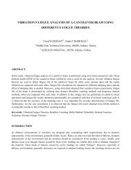
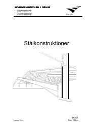
Using Pall Friction Dampers for Seismic Retrofit of a 4-Story Steel ...
Using Pall Friction Dampers for Seismic Retrofit of a 4-Story Steel ...
Using Pall Friction Dampers for Seismic Retrofit of a 4-Story Steel ...

Create successful ePaper yourself
Turn your PDF publications into a flip-book with our unique Google optimized e-Paper software.
<strong>Using</strong> <strong>Pall</strong> <strong>Friction</strong> <strong>Dampers</strong> <strong>for</strong> <strong>Seismic</strong> <strong>Retr<strong>of</strong>it</strong> <strong>of</strong> a 4-<strong>Story</strong><br />
<strong>Steel</strong> Building in Iran<br />
Seyed Mehdi Zahrai 1<br />
Alireza Moradi 1<br />
Mohammadreza Moradi 2<br />
1. Department <strong>of</strong> Civil Engineering, Islamic Azad University, Central Tehran Branch,<br />
Tehran Iran<br />
2. University <strong>of</strong> Guam, Mangilao Guam, 96921 moradi@uguam.uog.edu<br />
Abstract:<br />
Past earthquakes in Iran have caused severe damage to existing steel buildings without<br />
adequate resistance and ductility against earthquakes. Competent methods <strong>for</strong> seismic<br />
retr<strong>of</strong>itting are required in order to prevent damage and casualty. Among effective<br />
seismic retr<strong>of</strong>it methods, passive control reduces seismic vulnerability by mitigating<br />
seismic demand and increasing ductility. One <strong>of</strong> the most suitable methods in passive<br />
control system is to use pall friction damper in the braced steel structures. Main<br />
advantage <strong>of</strong> this friction damper is its almost rectangular <strong>for</strong>ce-de<strong>for</strong>mation hysteretic<br />
loops with high-energy dissipations, without any need to specific technology. In this<br />
paper, while introducing the per<strong>for</strong>mance <strong>of</strong> pall friction dampers and their design,<br />
seismic retr<strong>of</strong>it <strong>of</strong> an existing 4-story steel simple frame in Iran is investigated by using<br />
such dampers.<br />
Keywords:<br />
<strong>Seismic</strong> design and retr<strong>of</strong>it, pall friction damper, passive control, ductility, steel frame
1. Introduction:<br />
All the damages and losses during recent severe earthquakes have causes the concern <strong>of</strong><br />
finding an appropriate solution to stand against this natural disaster. Nowadays, applying<br />
new methods in structural seismic design, and improving the quality <strong>of</strong> the structural<br />
materials, are among the common approaches to accomplish this objective. Recent<br />
methods, which are based on distributing energy in structures, have been developed to<br />
control seismic vibrations and reduce the effect <strong>of</strong> the earthquake <strong>for</strong>ce. The large amount<br />
<strong>of</strong> energy is exerted into the structures during an earthquake, including potential and<br />
kinetic energy, which somehow needs to be damped in the structure. If there is no<br />
damping system, the structure vibrates continuously. But, in practice there is a damping<br />
system caused by structural properties, which creates some reactions against structural<br />
vibration. Moreover, per<strong>for</strong>mance <strong>of</strong> the building can be improved by installing an<br />
energy absorber (damper). In this method, dampers absorb and dissipate part <strong>of</strong> the<br />
earthquake energy.<br />
In this study, first, seismic vibration control <strong>of</strong> structures is presented and then, by<br />
considering friction dampers as one <strong>of</strong> the seismic vibration control methods, analytical<br />
evaluation <strong>of</strong> the effects <strong>of</strong> <strong>Pall</strong> friction dampers on the seismic response <strong>of</strong> the steel<br />
frame during earthquake is discussed.<br />
2. <strong>Seismic</strong> Vibration Control <strong>of</strong> Structures:<br />
Structural vibration control is actually an attempt to reduce structural displacement or<br />
acceleration, which are the main sources <strong>of</strong> structural damage during earthquake. There<br />
are several classifications to facilitate investigations about different control systems.<br />
These classifications are based on either dynamic properties <strong>of</strong> structures or location and<br />
distribution <strong>of</strong> the control system in the structures. Based on the latter classification, there<br />
are four control systems: Passive, Active, Semi-Active and Hybrid.
2.1 Passive Control Systems:<br />
A passive control system operates without requiring an external power source. This<br />
system consists <strong>of</strong> one or more devices designed to modify the structural properties such<br />
as ductility and stiffness and dissipate energy, leading to reduction in structural<br />
vibrations. <strong>Friction</strong> damper is a type <strong>of</strong> passive Control system [1].<br />
2.2 Active Control Systems:<br />
Unlike passive control system, active control systems require an external power source<br />
<strong>for</strong> operation and controlling structural vibrations. In these systems, special devices<br />
generate and apply <strong>for</strong>ces to the structure. These <strong>for</strong>ces act opposite direction <strong>of</strong> the<br />
destructive <strong>for</strong>ces and work as a damper. These systems need special equipments such as<br />
hydraulic actuator (as the external stimulator) and accurate control systems (sensitive<br />
receptor and hardware and s<strong>of</strong>tware equipment) [1].<br />
2.3 Semi-Active Control Systems:<br />
Comparing the per<strong>for</strong>mance <strong>of</strong> the active and passive control systems leads to<br />
development <strong>of</strong> semi-active control systems. In this system, the control <strong>for</strong>ce is<br />
developed through appropriate adjustment <strong>of</strong> the mechanical properties <strong>of</strong> the semi-active<br />
control system devices without applying external <strong>for</strong>ces. These devices can be defined as<br />
the passive control dampers. Since these devices are able to actively control the vibration<br />
without requiring high-level external power <strong>for</strong>ce, they have been used a lot recently.<br />
Some <strong>of</strong> these semi-active systems have the ability to operate just by using battery, which<br />
is a remarkable property, since it is probable that the main power source becomes<br />
disconnected during earthquake [1].<br />
2.4 Hybrid Control Systems:<br />
<strong>Using</strong> the combinations <strong>of</strong> active and passive control is called hybrid control system. The<br />
objective <strong>of</strong> developing such a system is to enhance the efficiency <strong>of</strong> the passive control<br />
system and to reduce the required external power in active control system. These systems
work similar to active control systems during low amplitude excitation (weak and<br />
medium earthquake). Actually in low amplitude excitation, external excitation is not<br />
large enough <strong>for</strong> appropriate per<strong>for</strong>mance <strong>of</strong> the passive control systems and active<br />
control system operates just by low level <strong>of</strong> external <strong>for</strong>ce. The hybrid control systems<br />
work similar to passive control systems during high amplitude excitation (strong<br />
earthquake). During high amplitude excitation, active control systems do not per<strong>for</strong>m<br />
properly because <strong>of</strong> the saturation limits on generating external power while the passive<br />
control system operates efficiently. Although, hybrid control system are more expensive,<br />
they are more efficient and have a better per<strong>for</strong>mance than the passive and active control<br />
system [1].<br />
3. <strong>Pall</strong> <strong>Friction</strong> <strong>Dampers</strong>:<br />
The most effective, reliable and economical method to dissipate energy and extract<br />
kinetic energy from a moving body is the friction brake. In 1979, the principle <strong>of</strong> friction<br />
brake inspired <strong>Pall</strong> and his colleagues and they started to develop the friction dampers <strong>for</strong><br />
structures. Actually, friction dampers use the mechanism <strong>of</strong> solid frictions to dissipate<br />
energy. Similar to automobiles, the motion <strong>of</strong> vibrating building can be reduced by<br />
dissipating energy in friction. These studies led to the development <strong>of</strong> the <strong>Pall</strong> friction<br />
damper in 1982 [2, 5]<br />
The <strong>Pall</strong> friction damper is made <strong>of</strong> a set <strong>of</strong> special steel plates, which can create the<br />
convenient frictional per<strong>for</strong>mance. These plates are bolted together with a high strength<br />
screws and they are designed not to slip during wind. These dampers slide over each<br />
other at the determined optimum slip load prior to yielding <strong>of</strong> structural members and<br />
dissipate the big portion <strong>of</strong> the earthquake energy. This makes the structure remain in the<br />
elastic range or delay the yielding <strong>of</strong> the structural member during major earthquake [3].<br />
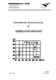
Figure 1 shows the details <strong>of</strong> the pall friction damper.
Figure 1: Details <strong>of</strong> the <strong>Pall</strong> friction damper<br />
Figure 2: Idealized hysteretic behavior <strong>of</strong> a simple one-storey friction damped frame [4]<br />
Figure 2 shows five stages <strong>of</strong> behavior <strong>of</strong> the pall friction dampers during a typical load<br />
cycle including de<strong>for</strong>med shape <strong>of</strong> the frame in each stage. Response <strong>of</strong> the frame<br />
member in each stage is described below [4]:
First stage: Both braces are active and behave elastically in tension and compression.<br />
Second stage: The compression brace buckles while the tension brace continues to<br />
behave elastically in tension.<br />
Third stage: Be<strong>for</strong>e yielding is started in the tension brace, the device is designed to slip.<br />
When slippage occurs, the four links are activated and de<strong>for</strong>m into a rhomboid shape; this<br />
de<strong>for</strong>mation pattern eliminate the buckled shape <strong>of</strong> the compression brace. There<strong>for</strong>e,<br />
after the slippage, the compression brace is still straight and the axial <strong>for</strong>ce in<br />
compression brace equals to buckling load.<br />
Forth stage: The straightened brace can immediately absorb energy in tension when the<br />
load is reversed.<br />
Fifth stage:<br />
Load in brace 1 becomes more than the buckling load and the second stage is<br />
repeated. This is followed by the third stage and cycle is completed.<br />
It should be noted that the <strong>Pall</strong> fiction dampers works properly if the device slips be<strong>for</strong>e<br />
the structural members and tensional brace yields or compressive brace de<strong>for</strong>ms<br />
significantly. Moreover, to be more efficient, slip load should be set such that the friction<br />
mechanism does not work during weak and medium earthquakes [4].<br />
4. <strong>Using</strong> <strong>Pall</strong> friction dampers to retr<strong>of</strong>it a 4-story steel frame:<br />
In this study, one <strong>of</strong> the internal frames <strong>of</strong> a 4-story steel frame is chosen <strong>for</strong> retr<strong>of</strong>itting.<br />
Since the old buildings in Iran do not have bracing as the lateral resistance system, a<br />
simple frame with hollow-tile as the floor system is considered. The building is hospital<br />
in a region with high risk <strong>of</strong> earthquake and the soil is type 3. Since the building is old, it<br />
was just designed <strong>for</strong> gravity load and not the lateral load. Dead load <strong>for</strong> the floors and<br />
ro<strong>of</strong> are 650 and 600 kg/m 2 respectively and live load <strong>for</strong> the floors and ro<strong>of</strong> are 300 and<br />
150 kg/m 2 respectively. These values are defined based on the Iranian National building<br />
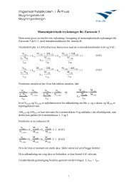
regulation part 6: Loading. Figure 3 shows location <strong>of</strong> pall friction dampers in the frame<br />
and floor plan. All the spans are five meters and each storey has 3 meters height in the<br />
steel frame. Frame was designed using ETABS-9.1.4 based on AISC–ASD89<br />
specification. Table 1 shows the in<strong>for</strong>mation <strong>of</strong> the structural members.
Figure 3: Location <strong>of</strong> the <strong>Pall</strong> friction damper in the frame and floor plan<br />
Table 1: Specification <strong>of</strong> the frame members<br />
Floor Beams Interior Columns Exterior Columns<br />
4 IPE330+PL120X5 BOX 100X5 BOX 100X5<br />
3 IPE330+ PL130X10 BOX 150X10 BOX 120X8<br />
2 IPE330+ PL130X10 BOX 150X10 BOX 120X10<br />
1 IPE330+ PL130X10 BOX 200X10 BOX 150X10
5. Design <strong>of</strong> the pall friction damper<br />
The crucial part <strong>of</strong> the design <strong>of</strong> friction dampers is to determine the optimum slip load.<br />
The movement <strong>of</strong> the damper in an elastic brace constitutes nonlinearity. Moreover, the<br />
amount <strong>of</strong> energy dissipation is proportional to the displacement. There<strong>for</strong>e, nonlinear<br />
time history dynamic analysis, which is used in this study, is an accurate procedure to<br />
find the value <strong>of</strong> the optimum slip load. In this method, structural response can be<br />
evaluated during and after earthquake [5,6].<br />
Hysteresis loop <strong>of</strong> the damper is similar to the rectangular loop <strong>of</strong> the material with<br />
elastic perfectly plastic behavior. There<strong>for</strong>e, sliding load is considered as virtual yielding<br />
<strong>for</strong>ce in bracing. PERFORM-3D [7] is used <strong>for</strong> nonlinear time history dynamic analysis<br />
<strong>of</strong> the frame with the dampers. The analyses are based on the Iranian Standard <strong>Seismic</strong><br />
Code No. 2800 third edition [8]. Three accelerographs, as presented in Table 2, are used<br />
in these analyses.<br />
Table 2: Specification <strong>of</strong> the Earthquake Records<br />
Earthquake Year Station Direction PGA (g) Soil Type Duration (s)<br />
Tabas 1978 9101<br />
H1<br />
H2<br />
0.836<br />
0.852<br />
III 32.84<br />
Imperial Valley 1979<br />
Bonds<br />
Corner<br />
H1<br />
H2<br />
0.588<br />
0.775<br />
III 37.61<br />
Cape Mendocino 1992<br />
89156<br />
Petrolia<br />
H1<br />
H2<br />
0.590<br />
0.662<br />
III 36<br />
In the analyses, yielding stress <strong>of</strong> the brace in tension is assigned equal to the stress in<br />
braces during sliding. The maximum displacements <strong>of</strong> the stories are considered as the<br />
frame response in nonlinear dynamic analysis. This procedure is per<strong>for</strong>med <strong>for</strong> different
values <strong>of</strong> yielding stress in tension. The sliding design load, which corresponds to the<br />
minimum structural response, is considered as the optimum sliding load.<br />
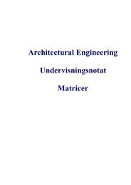
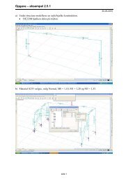
Figure 4 shows the maximum story drift in terms <strong>of</strong> sliding load and Figure 5 depicts the<br />
hysteresis loop <strong>of</strong> the bracing consisting <strong>of</strong> the friction damper <strong>for</strong> the frame under the<br />
Tabas earthquake.<br />
Envelope <strong>of</strong> Displacement (cm)<br />
4.5<br />
4<br />
3.5<br />
3<br />
2.5<br />
2<br />
1.5<br />
1<br />
0.5<br />
0<br />
0 10 20 30 40 50 60 70 80<br />
Slip Force (ton)<br />
Figure 4: The maximum story drift in terms <strong>of</strong> slip <strong>for</strong>ce under the Tabas earthquake<br />
It can be seen in Figure 4 that displacement is reduced by increasing the sliding load and<br />
after passing the sliding load <strong>of</strong> 25 ton, displacement increases. There<strong>for</strong>e, optimum<br />
sliding load is equal to 25 ton in all the stories.<br />
<strong>Story</strong> 1<br />
<strong>Story</strong> 2<br />
<strong>Story</strong> 3<br />
<strong>Story</strong> 4
6. The effect <strong>of</strong> the <strong>Pall</strong> friction damper on the ro<strong>of</strong> lateral displacement<br />
Figure 5 shows top floor drift <strong>for</strong> the frame with and without <strong>Pall</strong> friction damper under<br />
the Tabas earthquake. It can be seen that installing <strong>Pall</strong> friction damper in the frame<br />
reduces the maximum displacement 80%. This reduction is the result <strong>of</strong> the frame<br />
ductility caused by <strong>Pall</strong> friction damper absorbing in fact most portion <strong>of</strong> the earthquake<br />
energy that means the beams and columns absorb less energy and remain in elastic range.<br />
This leads to reduction <strong>of</strong> floor drift in the frame with <strong>Pall</strong> friction damper compared to<br />
the simple frame without <strong>Pall</strong> friction dampers.<br />
Figure 5: Top floor drift <strong>for</strong> the frame with and without <strong>Pall</strong> friction damper under the Tabas Earthquake<br />
7. Conclusion<br />
Since <strong>Pall</strong> friction dampers are cheap and have simple mechanism, they are considered as<br />
one <strong>of</strong> the decent methods in structural vibration control. In this paper, a simple 4-story
steel frame, which had a weak per<strong>for</strong>mance against earthquake, was retr<strong>of</strong>itted by adding<br />
pall friction damper. Nonlinear time history dynamic analysis was per<strong>for</strong>med on the<br />
frame by applying the Elcentro, Tabas and Cape Mendocino earthquake based on the<br />
2800 Iranian seismic code. Here is the result:<br />
• Optimum sliding load equal to 25 ton is achieved by per<strong>for</strong>ming time history<br />
dynamic analysis<br />
• Top floor drift is reduced 80% in the frame with <strong>Pall</strong> fiction damper compared to<br />
References:<br />
the frame without damper. This is the reason <strong>of</strong> dissipation <strong>of</strong> large portion <strong>of</strong> the<br />
earthquake energy by <strong>Pall</strong> friction damper.<br />
[1] Dole M. (1995), “Passive Control Of Structure”, Proceeding Of 10 th European<br />
Conference On Earthquake Engineering, Duma (ed), Rotterdam , pp, 1903-1912.<br />
[2] Soong T.T. And Dargush G.F., (1997), “Passive Energy Dissipation Systems In<br />
Structural Engineering” , 1 st edu. , John Wiley & Sons.<br />
[3] Friedriechs B., (1997), “<strong>Dampers</strong> Do The Job At Davis “, ASCE Journal Of<br />
Structural, Vol. 67, No. 9, pp. 2A-5A.<br />
[4] Cherry S., Filliatrault A., (1993), “<strong>Seismic</strong> Response Control Of Building <strong>Using</strong><br />
<strong>Friction</strong> <strong>Dampers</strong>”, EERI , Earthquake Spectra , Volume 9, Number 3, pp: 447-466.<br />
[5] Pasquin , <strong>Pall</strong> T., (2002), “<strong>Friction</strong> Damper For <strong>Seismic</strong> Rehabilitation Of Eaton<br />
Building Montreal”, 4th Structural Specialty Conference <strong>of</strong> Canadian Society <strong>for</strong> Civil<br />
Engineering<br />
[6] <strong>Pall</strong> R.T., <strong>Pall</strong> A., Leboeuf N., Pasquin C., 2004, “<strong>Friction</strong> Damper For <strong>Seismic</strong><br />
Rehabilition <strong>of</strong> Eaton Building , Montreal “ Thirteenth World Conference On Earthquake<br />
Engineering , Vancouver , Canada , Paper No.1949<br />
[7] Ram International, “RAM PERFROM-3D Version 4.0.1 User Guide”, Graham<br />
H.Powell, 2006<br />
[8] Building and Housing Research Center, Manual <strong>for</strong> design building in Iran against<br />
earthquake Standard No. 2800, Third Edition, 2005