Minimum Standard 3.09 - Constructed Stormwater Wetland - Virginia ...
Minimum Standard 3.09 - Constructed Stormwater Wetland - Virginia ...
Minimum Standard 3.09 - Constructed Stormwater Wetland - Virginia ...

Create successful ePaper yourself
Turn your PDF publications into a flip-book with our unique Google optimized e-Paper software.
MINIMUM STANDARD <strong>3.09</strong> CHAPTER 3<br />
MINIMUM STANDARD <strong>3.09</strong><br />
CONSTRUCTED<br />
STORMWATER WETLAND
MINIMUM STANDARD <strong>3.09</strong> CHAPTER 3
MINIMUM STANDARD <strong>3.09</strong> CHAPTER 3<br />
LIST OF ILLUSTRATIONS<br />
# FIGURES PAGE<br />
<strong>3.09</strong>-1 <strong>Constructed</strong> <strong>Stormwater</strong> <strong>Wetland</strong>s - Plan ......................... <strong>3.09</strong>-16<br />
<strong>3.09</strong>-2 <strong>Constructed</strong> <strong>Stormwater</strong> <strong>Wetland</strong>s - Depth Zones .................. <strong>3.09</strong>-16<br />
<strong>3.09</strong>-3 Dry Weather and Wet Weather Flow Paths ........................ <strong>3.09</strong>-17<br />
<strong>3.09</strong>-4 Off-line Bypass Structure ..................................... <strong>3.09</strong>-18<br />
# TABLES PAGE<br />
<strong>3.09</strong>-1 Pollutant Removal Efficiency for <strong>Constructed</strong> <strong>Stormwater</strong> <strong>Wetland</strong>s .... <strong>3.09</strong>-2<br />
<strong>3.09</strong>-2 Recommended Allocation of Surface Area and Treatment Volume for<br />
Various Depth Zones ......................................... <strong>3.09</strong>-10<br />
<strong>3.09</strong>-3 Clay Liner Specifications ...................................... <strong>3.09</strong>-12
MINIMUM STANDARD <strong>3.09</strong> CHAPTER 3
MINIMUM STANDARD <strong>3.09</strong> CHAPTER 3<br />
MINIMUM STANDARD <strong>3.09</strong><br />
CONSTRUCTED STORMWATER WETLAND<br />
Definition<br />
<strong>Constructed</strong> stormwater wetlands are manmade shallow pools that create growing conditions<br />
suitable for both emergent and aquatic vegetation.<br />
Purpose<br />
<strong>Constructed</strong> wetlands are intentionally installed on non-wetland sites to enhance the quality of<br />
stormwater runoff.<br />
In contrast, created wetlands are also intentionally installed on non-wetland sites, but are designed<br />
to produce or replace natural functional wetlands and wetland habitats (e.g., for compensatory<br />
mitigation projects).<br />
This handbook deals primarily with constructed wetlands. Sometimes, a constructed wetland may<br />
provide some of the benefits of a created wetland. However, understanding the differences in these<br />
two manmade systems is important. For a natural or created wetland, pre-treatment BMPs, such<br />
as erosion controls, presettling basins, biofilters, etc., are used to reduce pollutants entering the<br />
wetland to prevent its degradation and clogging. The primary function of a constructed wetland,<br />
on the other hand, is to provide those same types of pre-treatment functions within the wetland itself.<br />
The constructed wetland, therefore, will require maintenance to assure long-term pollutant removal.<br />
It should be noted that the pre-treatment BMPs mentioned above will often simplify or reduce<br />
maintenance requirements, as well as enhance and prolong the useful life of a constructed<br />
stormwater wetland.<br />
Water Quality Enhancement<br />
A constructed stormwater wetland can achieve high removal rates of particulate and soluble<br />
pollutants (nutrients) through gravitational settling, wetland plant uptake, absorption, physical<br />
filtration, and biological decomposition. The pollutant removal efficiency of a constructed wetland<br />
is dependent on various design criteria relating to the size and design of the pool area. Other sitespecific<br />
design features and variations in environmental conditions such as soils, climate, hydrology,<br />
<strong>3.09</strong> - 1
MINIMUM STANDARD <strong>3.09</strong> CHAPTER 3<br />
etc. make it difficult to predict the actual pollutant removal efficiency. Monitoring of many<br />
stormwater wetland facilities has confirmed the wide range of pollutant removal efficiencies<br />
associated with such systems.<br />
<strong>Constructed</strong> stormwater wetlands operate similar to retention basins, yet their overall performance<br />
is expected to be more variable. This may be due to any of the following:<br />
1. The decrease in biological activity associated with seasonal cold weather.<br />
2. The conversion of plant species and densities as the wetland matures and becomes<br />
acclimated to various environmental factors such as soils, hydrology, climate, and sediment<br />
and pollutant load.<br />
3. The uncertainty of the biological cycling processes of phosphorous in the wetland<br />
environment.<br />
The expected pollutant removal rate of constructed stormwater wetlands is provided in Table <strong>3.09</strong>-1.<br />
While the rate may appear low, it reflects the uncertainty of their long-term viability.<br />
TABLE <strong>3.09</strong> - 1<br />
Pollutant Removal Efficiency for <strong>Constructed</strong> <strong>Stormwater</strong> <strong>Wetland</strong>s<br />
Water Quality BMP<br />
<strong>Constructed</strong> <strong>Wetland</strong>s<br />
2.0 x WQ Volume<br />
Flood Control & Channel Erosion Control<br />
Target Phosphorus<br />
Removal Efficiency<br />
<strong>3.09</strong> - 2<br />
Impervious Cover<br />
30% 22 - 37%<br />
<strong>Constructed</strong> stormwater wetlands should generally not be used for flood control or stream channel<br />
erosion control. This is due to the anticipated water level fluctuations associated with quantity<br />
controls. The clearing of vegetation and the addition of impervious surfaces may cause large and<br />
sudden surges of runoff during rain events, and may cause less than normal base flows due to lack<br />
of groundwater during dry periods. Large, sudden fluctuations in water levels can stress emergent<br />
wetland and upland edge vegetation. Most edge vegetation cannot survive drought or saturation<br />
extremes, leaving wetland banks exposed to potential erosion. It should be noted that the large<br />
surface area requirement for constructed stormwater wetlands will help to minimize the “extreme”<br />
water level fluctuations during all but the larger storm events. Also, certain plants can be specified<br />
for the upland banks which may be more tolerant to the wet and dry extremes. Therefore, preventing<br />
surges whenever possible and designing for gradual increases and decreases in water level is
MINIMUM STANDARD <strong>3.09</strong> CHAPTER 3<br />
important for successful constructed wetland design. See Design Criteria for further discussion.<br />
(<strong>Wetland</strong> vegetation can be used to enhance the pollutant removal efficiency of extended-detention<br />
flood control and stream channel erosion control facilities by constructing a shallow marsh in their<br />
bottoms. See <strong>Minimum</strong> <strong>Standard</strong> 3.07, Extended-Detention and Enhanced Extended-Detention<br />
Basin.)<br />
Drainage Area<br />
Conditions Where Practice Applies<br />
The drainage area criteria for a constructed stormwater wetland is similar to that of a retention basin.<br />
However, because of their shallow depth, constructed stormwater wetlands may consume two to<br />
three times the site area compared with other stormwater quality BMPs (MWCOG, 1992). Vertical<br />
(depth) storage is usually not possible in constructed wetlands due to the needs of aquatic plants.<br />
Therefore, the maximum watershed size depends on the available area on the site that is suitable for<br />
a constructed wetland system.<br />
The minimum watershed drainage area for constructed stormwater wetlands should be 10 acres.<br />
However, this minimum should be confirmed based on the watershed’s hydrology and the presence<br />
of an adequate base flow to support the selected vegetation. Similar to retention basins, a drainage<br />
area of 15 to 20 acres or the presence of a dependable base flow is most desirable to maintain a<br />
healthy wetland. A clay liner may be necessary to prevent infiltration if losses are expected to be<br />
high.<br />
Development Conditions<br />
<strong>Constructed</strong> stormwater wetlands are suited for both low- and high-visibility sites. However, the<br />
aesthetic problems associated with having a natural and free growing landscape feature in an<br />
otherwise manicured development setting should be avoided for high-visibility sites. Additional<br />
concerns regarding stagnation or excessive infiltration during the dry summer months may also<br />
influence the choice of location. Proper planning, design, and maintenance are critical to ensure<br />
the pollutant removal capabilities of a constructed wetland and to insure its acceptance by adjacent<br />
landowners.<br />
Like retention basins, constructed wetlands are also suited for low- and medium-density residential<br />
or commercial developments. However, the land area required for this BMP may limit its use.<br />
<strong>3.09</strong> - 3
MINIMUM STANDARD <strong>3.09</strong> CHAPTER 3<br />
Planning Considerations<br />
<strong>Constructed</strong> stormwater wetlands should be designed to duplicate the functions of natural wetlands,<br />
while allowing for ongoing maintenance. The designer faces the difficult task of replicating natural<br />
wetland hydrology in a constructed setting, while ensuring easy access for maintenance.<br />
Hydrology<br />
The hydrology of a constructed stormwater wetland is largely influenced by surface runoff. The<br />
hydrology, in turn, affects several key characteristics of a stormwater wetland, such as:<br />
1. Water level fluctuations. A constructed stormwater wetland will experience rapid<br />
inundation and drawdown periods with each runoff-producing event.<br />
2. Permanent pool. A natural wetland may experience seasonal standing water and/or periodic<br />
drawdowns. However, a constructed stormwater wetland is engineered to permanently hold<br />
a specific volume of water, or at a minimum, maintain pools of water of varying depths. This<br />
stored water supports the aquatic and emergent plant regime and maintains the pollutant<br />
removal efficiency of the BMP.<br />
3. Vegetation. The vegetation diversity in a constructed wetland is established by the landscape<br />
plan or volunteer vegetation. The selection of vegetation should be limited to native plant<br />
species suitable for the pool depths expected within the different depth zones. Care should<br />
be taken to avoid the introduction of exotic or invasive species. The use of appropriate<br />
donor soil and wetland mulch will help prevent this problem.<br />
In contrast, a natural wetland vegetates itself through natural selection based on the growing<br />
conditions within it. The existing source of seeds, which is usually enhanced by wildlife,<br />
allows for the constant renewal of plant life.<br />
4. Sediment and pollutant load. A stormwater wetland is subject to sediment loads, especially<br />
from upland pervious areas during the first growing season. During this period, permanent<br />
vegetation in the developing watershed is still growing. Without a well-established ground<br />
cover, surface sediments can be easily transported by rainfall and resulting runoff.<br />
Accumulation of this sediment in the constructed stormwater wetland during the first<br />
growing season alone can dramatically alter the topography of the facility, affecting water<br />
levels and flow paths. Furthermore, the pollutant load (nutrients and organics) associated<br />
with urban runoff and sediments entering a constructed wetland is usually higher than that<br />
which enters a natural or undisturbed wetland in undeveloped watershed. Therefore, if the<br />
constructed wetland is used to remove pollutants, the water quality within the wetland itself<br />
will be decreased. During the planning stage of a facility, the designer should have a good<br />
understanding of site-specific runoff constituents and an understanding of their possible<br />
effects on the selected vegetation.<br />
<strong>3.09</strong> - 4
MINIMUM STANDARD <strong>3.09</strong> CHAPTER 3<br />
Site Conditions<br />
Site conditions, such as property lines, easements, utilities, structures, etc., that may impose<br />
constraints on development should be considered when designing a constructed wetland. Local<br />
government land use and zoning ordinances may also specify certain requirements.<br />
All facilities should be a minimum of 20 feet from any structure, property line, or vegetative buffer,<br />
and 100 feet from any septic tank/drainfield. Local landuse setbacks and other restrictions may<br />
apply.<br />
All facilities should be a minimum of 50 feet from any steep slope (greater than 10%).<br />
Alternatively, a site-specific geotechnical report must address the potential impact of a constructed<br />
stormwater wetland that is to be installed on, or near, such a slope.<br />
Additional considerations are as follows:<br />
1. Soils–<br />
Permeable soils are not suited for constructed stormwater wetlands. A thorough analysis<br />
of the soil strata should be conducted to verify its suitability for holding water. In the past,<br />
many BMP designs were accepted based upon soils information compiled from available<br />
data, such as SCS soil surveys. While such a source may be appropriate for a preengineering<br />
feasibility study, final design and acceptance should be based on an actual<br />
subsurface analysis and permeability tests, accompanied by appropriate engineering<br />
recommendations. Refer to the references listed at the end of <strong>Minimum</strong> <strong>Standard</strong> 3.10,<br />
Infiltration Practices for additional information on soil analysis techniques.<br />
The goal of a subsurface analysis is to determine if the soils are suitable for a constructed<br />
stormwater wetland. The textural character of the soil horizons and/or strata units within the<br />
subsoil profile should be identified to at least 3 feet below the bottom of the facility. This<br />
information is used to verify the infiltration rate or permeability of the soil. For constructed<br />
stormwater wetlands, water inflow (base flow and groundwater) must be greater than water<br />
losses (infiltration and evaporation). If the infiltration rate of the soil is too great, then a<br />
constructed wetland may not be an appropriate BMP, or a liner may be required. The soil<br />
permeability may be such that the shallow depths of a constructed wetland can be<br />
maintained. However, as the depth of the permanent pool increases, the increased head or<br />
pressure on the soil may increase the infiltration rate.<br />
For discussions regarding the appropriate soils for landscaping, see the Landscape section<br />
in this standard and <strong>Minimum</strong> <strong>Standard</strong> 3.05, Landscaping.<br />
<strong>3.09</strong> - 5
MINIMUM STANDARD <strong>3.09</strong> CHAPTER 3<br />
2. Rock–<br />
The subsurface investigation should also identify the presence of any rock or bedrock layers.<br />
The excavation of rock to achieve the proper wetland dimensions and hydrology may be too<br />
expensive or difficult with conventional earth moving equipment. However, blasting may<br />
open seams or create cracks in the underlying rock that may result in unwanted drawdown<br />
of the permanent pool. Blasting of rock is not recommended unless a liner is used.<br />
3. Karst–<br />
In regions where Karst topography is prevalent, projects may require a thorough soils<br />
investigation and specialized design and construction techniques. Since the presence of karst<br />
may affect BMP selection, design, and cost, a site should be evaluated during the planning<br />
phase of the project.<br />
4. Existing Utilities–<br />
Most utility companies will not allow their underground lines and right-of-ways to be<br />
submerged under a permanent pool. If such a site must be used, the designer should obtain<br />
permission before designing the BMP. Note that if the utilities ever require maintenance<br />
or repair, the characteristics of the constructed wetland may be irreparably changed or<br />
damaged. The cost to move any existing utilities during initial wetland construction should<br />
be determined and included in the project’s overall construction costs.<br />
Environmental Impacts<br />
<strong>Constructed</strong> stormwater wetlands are generally located in areas with favorable hydrology. These<br />
locations are prone to being environmentally sensitive (low-lying) as well, and may contain existing<br />
wetlands, shallow marshes, perennial streams, wildlife habitat, etc., which may be protected by state<br />
or federal laws. The owner or designer should review local wetland maps and contact local, state,<br />
and federal permitting agencies to verify the presence of wetlands, their protected status, and the<br />
suitability of the location for a constructed wetland.<br />
With careful planning, it may be possible to incorporate wetland mitigation into a constructed<br />
stormwater wetland. This assumes that the functional value of the existing or impacted wetland can<br />
be identified and included, reconstructed, or mitigated for, in the stormwater wetland. The <strong>Virginia</strong><br />
Department of Environmental Quality should be contacted for more information regarding wetland<br />
mitigation.<br />
<strong>3.09</strong> - 6
MINIMUM STANDARD <strong>3.09</strong> CHAPTER 3<br />
Sediment Control<br />
A constructed stormwater wetland should not be used as a sediment control facility during site<br />
construction. A presettling basin, or forebay, may be constructed above the proposed constructed<br />
wetland facility, however, any planting or preparation of the constructed wetland site should occur<br />
after the site construction has been completed. This will eliminate any forseeable impact from<br />
sediment loads that overwhelm temporary erosion and sediment control measures during storm<br />
events.<br />
Maintenance<br />
<strong>Constructed</strong> stormwater wetlands require periodic maintenance, as does any stormwater BMP. In<br />
addition, a constructed wetland will require active management of the hydrology and vegetation<br />
during the first few years or growing seasons in order for it to achieve the performance and functions<br />
for which it was designed.<br />
Vehicular access and manuvering room in the vicinity of a constructed wetland (and sediment<br />
forebay) is necessary to allow for long-term maintenance. In addition, the establishment of an onsite<br />
sediment disposal area, properly located and contained, will significantly reduce the cost of<br />
routine maintenance and sediment removal. Care must be taken in the disposal of sediment that may<br />
contain an accumulation of heavy metals. Sediment testing is recommended prior to sediment<br />
removal to assure proper disposal.<br />
Design Criteria<br />
This section provides minimum criteria and recommendations for the design of a constructed<br />
stormwater wetland intended to comply with the runoff quality requirements of the <strong>Virginia</strong><br />
<strong>Stormwater</strong> Management program. It is the designer’s responsibility to decide which aspects of the<br />
program apply to the particular facility being designed and if any additional design elements are<br />
required to insure the long-term functioning of the wetland.<br />
Hydrology and Hydraulics<br />
Chapter 4, Hydrologic Methods and Chapter 5, Engineering Calculations should be used to<br />
develop the post-developed hydrology of the wetland’s contributing watershed, to analyze the<br />
hydraulics of the riser and barrel system (if used) and to design the emergency spillway.<br />
The contributing watershed’s area should be a minimum of 10 acres and/or there should be an<br />
adequate base flow to support the hydrology.<br />
<strong>3.09</strong> - 7
MINIMUM STANDARD <strong>3.09</strong> CHAPTER 3<br />
Embankment<br />
The design of the earthen embankment for any impoundmant BMP should comply with <strong>Minimum</strong><br />
<strong>Standard</strong> 3.01, Earthen Embankment. Specific requirements for geotechnical analysis, seepage<br />
control, maximum slopes, and freeboard are particularly appropriate.<br />
Principal Spillway<br />
The design of the principal spillway and barrel system, or weir overflow system, anti-vortex device,<br />
and trash racks should comply with <strong>Minimum</strong> <strong>Standard</strong> 3.02, Principal Spillway. Weir spillways<br />
have a large cross-sectional area that can pass a considerable flow rate at low head conditions. Since<br />
reducing the depth of ponding in a constructed wetland helps to avoid stressing plant communities,<br />
an armored, weir-type spillway may be the most desirable overflow device for a constructed<br />
stormwater wetland. Further, the use of an adjustable weir will help maintain the proper water<br />
surface elevation during seasonal extremes.<br />
Emergency Spillway<br />
An emergency spillway that complies with <strong>Minimum</strong> <strong>Standard</strong> 3.03, Vegetated Emergency<br />
Spillway should be provided when possible.<br />
Permanent Pool<br />
Sizing a constructed stormwater wetland is based on maximizing its pollutant removal efficiency.<br />
The physical and hydraulic factors that influence the wetland’s pollutant removal efficiency are the<br />
permanent pool volume, depth, surface area, geometry, and hydraulic residence time. <strong>Minimum</strong><br />
design criteria are presented below for each of these factors:<br />
1. Volume –<br />
The required permanent pool volume of a constructed stormwater wetland is 2 times the water<br />
quality volume (2 ×WQV). The target pollutant removal efficiency shown in Table <strong>3.09</strong>-1 is based<br />
on this sizing criteria.<br />
2. Depth –<br />
Four depth zones are needed within the permanent pool of a constructed stormwater wetland: a) deep<br />
pool, b) low marsh, c) high marsh, and d) semi-wet (see Figure <strong>3.09</strong>-2).<br />
a. The deep pool areas of a constructed wetland should be 18 inches to 6 feet in depth and may<br />
consist of 1) sediment forebays, 2) micro-pools, and/or 3) deep-water channels.<br />
1. Sediment forebays are highly recommended in constructed stormwater wetlands.<br />
They should be installed at stormwater inflow points to reduce the velocity of<br />
<strong>3.09</strong> - 8
MINIMUM STANDARD <strong>3.09</strong> CHAPTER 3<br />
incoming runoff and trap course sediments, and to spread the runoff evenly over the<br />
wetland area. The forebay should be constructed as a separate cell from the rest of<br />
the wetland and provide easy access for maintenance with heavy equipment. Refer<br />
to <strong>Minimum</strong> <strong>Standard</strong> 3.04, Sediment Forebay for further information.<br />
2. Micro-pools offer open water areas to attract plant and wildlife diversity. If a lowflow<br />
discharge pipe is used, it should be constructed on a reverse slope and extended<br />
into the wetland below the pool surface elevation but above the bottom elevation.<br />
This helps to prevent clogging, since a typical wetland environment consists of<br />
floating plant debris and possible sediment and organic accumulation at the bottom.<br />
(Refer to the Overflow discussion later in this section.)<br />
3. Deep-water channels provide an opportunity to lengthen the flow path to avoid<br />
seasonal short-circuiting (see pool geometry).<br />
b. The low-marsh zone ranges in depth from 6 to 18 inches.<br />
c. The high-marsh zone ranges in depth from 0 to 6 inches. Usually, this zone will support the<br />
greatest density and diversity of emergent plant species.<br />
d. The semi-wet zone refers to the area that, during normal, non-rainfall periods, is above the<br />
pool, but is inundated during storm events for a period of time, depending on the amount of<br />
rainfall, and the hydraulics of the overflow device.<br />
Note: The low-marsh, high-marsh, and semi-wet zones are useful as a perimeter shelf 10 to 15 feet<br />
wide. This shelf, or aquatic bench, can serve as a safety feature to keep children away from the open<br />
water deep pool areas. Also, as a secondary benefit, a heavily vegetated perimeter will help to<br />
discourage geese from using the facility as a permanent habitat.<br />
The recommended surface area allocation for these depth zones is presented in Table <strong>3.09</strong>-2.<br />
3. Surface Area–<br />
At a minimum, the pool surface area of a constructed stormwater wetland should equal 2% of the<br />
size of the contributing watershed. Recommended surface area allocations for different depth zones<br />
are shown in Table <strong>3.09</strong>-2 (MWCOG, 1992). Note that if the surface area criteria conflict with the<br />
volume allocations, the surface area allocations are more critical to an effective design.<br />
4. Geometry–<br />
The geometry of the constructed stormwater wetland must be designed to avoid short-circuiting.<br />
Maximum pollutant removal efficiency is achieved with the longest possible flow path, since this<br />
increases the contact time over the wetland area. The minimum length-to-width ratio of the pool<br />
should be 1:1 in wet weather and 2:1 during dry weather (see Figure <strong>3.09</strong>-3).<br />
<strong>3.09</strong> - 9
MINIMUM STANDARD <strong>3.09</strong> CHAPTER 3<br />
TABLE <strong>3.09</strong>-2<br />
Recommended Allocation of Surface Area and Treatment Volume for Various Depth Zones<br />
Depth Zone % of Surface Area % of Treatment Volume<br />
Deep Water<br />
1.5 to 6 feet deep 10 20<br />
Low Marsh<br />
0.5 to 1.5 feet deep 40 *<br />
High Marsh<br />
0 to 0.5 feet deep 50 *<br />
* combined marsh area =<br />
80% of treatment volume<br />
Adapted from MWCOG, 1992<br />
The wet weather length-to-width ratio is calculated by dividing the straight line distance from the<br />
inlet to the outlet by the wetland’s average width. The dry weather length-to-width ratio is<br />
calculated by dividing the dry weather flow path length by the wetland’s average width. Note that<br />
the dry weather flow path is created by constructing high marsh areas perpendicular to the straight<br />
line flow path described above. These marsh areas act as submerged berms and lengthen the<br />
effective flow path.<br />
5. Hydraulic Residence Time–<br />
The hydraulic residence time is the permanent pool volume, divided by the average outflow<br />
discharge rate. The longer the residence time, the higher the pollutant removal efficiency (Driscoll,<br />
1983, Kulzer, 1989).<br />
Using 2 × WQV to size the permanent pool means that smaller storms (1 × WQV or ½-in.) will<br />
displace only half of the pool volume of the wetland, thus providing for extended residence times.<br />
Larger treatment volumes with respect to the watershed size (3 × WQV) will provide longer<br />
residence times and, therefore, greater efficiencies. In certain situations, using these larger volumes<br />
and efficiencies may be acceptable, but the decision should be made carefully. The associated<br />
challenge is to provide the recommended surface area allocations for the different depth zones as<br />
previously discussed.<br />
Overflow<br />
Providing flood control and/or channel erosion control within a constructed stormwater wetland<br />
creates a hydrologic regime that is very difficult to adapt to in the landscaping plan, due to extreme<br />
water depth fluctuations. If a constructed wetland is to serve as a quantity control BMP, it should<br />
<strong>3.09</strong> - 10
MINIMUM STANDARD <strong>3.09</strong> CHAPTER 3<br />
be designed to provide adequate overflow or bypass for the full range of design storms with as little<br />
vertical ponding depth as possible. The hydraulic head needed to pass a design storm is a function<br />
of the relationship between the constructed wetland surface area, the geometry of the overflow<br />
structure, and the allowable discharge (refer to Chapter 5, Engineering Calculations). Outlet<br />
structures should be sized to pass the design storms (up to the 10-year storm) with a maximum of<br />
2 feet of water ponded above the wetland pool.<br />
In a stormwater wetland designed for water quality enhancement only, a bypass or diversion<br />
structure may be used to prevent sudden surges of runoff from flushing through the wetland (see<br />
Figure <strong>3.09</strong>-4). This establishes the constructed wetland as an off-line facility. If site constraints<br />
prevent the use of an off-line facility, then the overflow should be designed to pass the full range<br />
of design storms with as little head as possible. An oversized riser and barrel system or a weir<br />
structure installed along the berm at the outlet may be used. Refer to <strong>Minimum</strong> <strong>Standard</strong> 3.02,<br />
Principal Spillway for outlet structure design criteria.<br />
Sediment Forebay<br />
Sediment forebays should be installed and designed per <strong>Minimum</strong> <strong>Standard</strong> 3.04, Sediment<br />
Forebay. Generally, they should be constructed at the outfall of incoming storm drain pipes or<br />
channels and should be made accessible for maintenance equipment. To lower maintenance costs,<br />
an on-site disposal area should be included in the design. Sediment forebays enhance the pollutant<br />
removal efficiency of BMPs by containing incoming sediment in one area, which also simplifies<br />
monitoring and removal. Therefore, the target pollutant removal efficiency of a constructed<br />
stormwater wetland, as presented in Table <strong>3.09</strong>-1, is predicated on the use of sediment forebays at<br />
all inflow points.<br />
Liner to Prevent Infiltration<br />
<strong>Constructed</strong> stormwater wetlands should have negligible infiltration rates through their bottom.<br />
Infiltration impairs the proper functioning of any retention facility by lowering its pool elevation.<br />
If infiltration is expected, then a retention BMP must not be used, or a liner should be installed to<br />
prevent infiltration. If a clay liner is used, the specifications provided in Table <strong>3.09</strong>-3 apply and the<br />
following are recommended:<br />
1. A clay liner should have a minimum thickness of 12 inches.<br />
2. A layer of compacted topsoil (6 to 12 inches thick, minimum) should be placed over the<br />
liner.<br />
3. Other liners may be used if adequate documentation exists to show that the material will<br />
provide the required performance.<br />
<strong>3.09</strong> - 11
MINIMUM STANDARD <strong>3.09</strong> CHAPTER 3<br />
Safety<br />
The side slopes of a constructed stormwater wetland should be no steeper than 3H:1V. Also, local<br />
ordinances may require fencing of deep pool areas next to the shoreline as an additional safety<br />
measure. Dense plantings of shoreline fringe vegetation can serve as a safety feature by<br />
discouraging access to the pool areas.<br />
TABLE <strong>3.09</strong> - 3<br />
Clay Liner Specifications<br />
Property Test Method (or equal) Unit Specification<br />
Permeability ASTM D-2434 cm/sec 1 x 10 -6<br />
Clay Plasticity Index ASTM D-423 & D-424 % Not less than 15<br />
Liquid Limit of Clay ASTM D-2216 % Not less than 30<br />
Clay Particles Passing ASTM D-422 % Not less than 30<br />
Clay Compaction ASTM D-2216 % 95% of <strong>Standard</strong> Proctor<br />
Density<br />
Source: City of Austin, 1988<br />
Access<br />
A 10 to 12-foot wide access road with a maximum grade of 12% should be provided to allow<br />
vehicular access to the outlet structure area, at least one side of the basin, and the sediment<br />
forebay(s). The road’s surface should be selected to support the anticipated frequency of use and<br />
vehicular load without excessive erosion or damage.<br />
Landscaping<br />
A qualified individual should prepare the landscape plan for a constructed stormwater wetland.<br />
Appropriate aquatic, emergent, shoreline fringe, transitional, and floodplain terrace vegetation must<br />
be selected to correspond with the expected frequency, duration, and depth of inundation.<br />
The landscaping plan for a constructed wetland is based on the projected depth zones and onsite soil<br />
analysis, and should contain the following:<br />
1. The location, quantity, and propagation methods of plant species and grasses for the<br />
stormwater wetland and its buffer.<br />
The location of plants is based on the depth zones in the wetland and the innundation tolerance of<br />
the plant species. Planting zones of uniform depth should be identified for each species selected.<br />
<strong>3.09</strong> - 12
MINIMUM STANDARD <strong>3.09</strong> CHAPTER 3<br />
Only one-half of the low- and-high marsh depth zones need to be planted. If the appropriate<br />
planting depths are achieved, the entire wetland should be colonized within three years. At least 5<br />
to 7 emergent wetland species, including a minimum of two species for each of the marsh depth<br />
zones (high and low), should be used. Selections should be based on wildlife food value, depth<br />
tolerance, price, commercial availability and/or shade limitations. Certain species, such as cattails,<br />
should be selected with caution. Although they may provide excellent pollutant removal<br />
characteristics, they can be invasive and may eventually crowd out other species.<br />
A constructed stormwater wetland does not contain a seed bank, nor does it have an existing natural<br />
seed transport cycle as found in native wetlands. While the use of donor soil from disturbed or<br />
dredged sites may provide a seed bank, these opportunities may not be readily available. Therefore,<br />
the most common and convenient technique for establishing wetland vegetation in a constructed<br />
system is to transplant nursery-grown stock. Other propagation techniques (which are outside the<br />
scope of this manual) may also prove successful, but special growing conditions must exist.<br />
2. Instructions for site preparation.<br />
The soil in which the vegetation is planted should be appropriate for the wetland plants selected. Soil<br />
tests showing the adequacy of the soil, or a soil enhancement plan should be submitted with the<br />
wetland design.<br />
The soil substrate must be soft enough to permit easy insertion of the plants. If the basin soil is<br />
compacted or vegetation has formed a dense root mat, the upper 6 inches of soil should be disked<br />
before planting. If soil is imported, it should be laid at least 4 inches deep to provide sufficient<br />
depth for plant rooting.<br />
3. A schedule for transplanting emergent wetland stock.<br />
The window for transplanting emergent stock extends from early April to mid-June. Dormant<br />
rhizomes can be planted in fall or winter. To insure availability, ordering stock 3 to 6 months in<br />
advance may be necessary.<br />
4. Planting procedures.<br />
A landscape plan should describe any special procedures for planting nursery stock. Most emergent<br />
plants may be planted in flooded or dry conditions. If planting is done in dry conditions, then<br />
instructions should be included for flooding the wetland immediately following installation.<br />
Proper handling of nursery stock is crucial. The roots must be kept moist to prevent damage. Plants<br />
received from the nursery will be in peat pots or bare-rooted. Bare-rooted plants will have some<br />
form of protection to keep the roots moist and may be kept for several days, but out of direct<br />
sunlight. For the maximum chance of success, all nursery stock should be planted as soon as<br />
possible. A minimum acceptable success rate of the plantings should be specified in the plan.<br />
<strong>3.09</strong> - 13
MINIMUM STANDARD <strong>3.09</strong> CHAPTER 3<br />
5. A maintenance and vegetation reinforcement schedule for the first three years after<br />
construction.<br />
Sometimes additional stabilization of the basin area may be necessary to ensure that the vegetation<br />
becomes established and mature prior to the erosion of the planting soil. Annual grasses may be<br />
used for this purpose. However, the specified application rates in the <strong>Virginia</strong> Erosion and Sediment<br />
Control Handbook (VESCH), 1992 edition: Temporary Seeding Spec. 3.31 should be reduced to<br />
help prevent these grasses from competing with other plants, particularly those emerging from bulbs<br />
and rhizomes. Overall, permanent seeding (VESCH Spec. 3.32) should be prohibited in zones 1<br />
through 4, as the grasses will indefinitely compete with the wetland plants. Refer to the Maintenance<br />
and Inspection section in this standard for more information.<br />
Additional considerations and criteria for developing a landscape plan can be found in <strong>Minimum</strong><br />
<strong>Standard</strong> 3.05, Landscaping.<br />
Buffer Zones<br />
A minimum 20-foot wide vegetated buffer, measured from the maximum water surface elevation,<br />
should be maintained beside the wetland. Refer to <strong>Minimum</strong> <strong>Standard</strong> 3.05, Landscaping.<br />
Construction Specifications<br />
Overall, widely accepted construction standards and specifications, such as those developed by the<br />
USDA Soil Conservation Service or the U.S. Army Corps of Engineers for embankment ponds and<br />
reservoirs, should be followed to build the impoundment.<br />
Further guidance can be found in Chapter 17 of the Soil Conservation Service’s Engineering Field<br />
Manual. Specifications for the work should conform to methods and procedures specified for<br />
earthwork, concrete, reinforcing steel, pipe water gates, metal work, woodwork and masonry and<br />
any other items that apply to the site and the purpose of the structure. The specifications should also<br />
satisfy any requirements of the local government.<br />
Guidance and construction specifications in the following minimum standards also apply for various<br />
components of the facility: 3.01, Earthen Embankment; 3.02, Principal Spillway; 3.03,<br />
Vegetated Emergency Spillway; 3.04, Sediment Forebay; and 3.05, Landscaping.<br />
<strong>3.09</strong> - 14
MINIMUM STANDARD <strong>3.09</strong> CHAPTER 3<br />
Maintenance and Inspections<br />
A constructed stormwater wetland may be maintained without a permit from the U. S. Army Corps<br />
of Engineers or the <strong>Virginia</strong> Department of Environmental Quality (Va. DEQ).<br />
Any pre-treatment facility or diversion structure should be inspected and maintained regularly to<br />
remove floatables and any large debris. Sediment should be removed from the forebay every 3 to<br />
5 years, or when 6 to 12 inches have accumulated, whichever comes first. To clean the forebay,<br />
draining or pumping and a possible temporary partial drawdown of the pool area may be required.<br />
Refer to the VESCH, 1992 edition for proper dewatering methods. A predesignated spoil area, away<br />
from the wetlands, should be used.<br />
The constructed stormwater wetland should be inspected at least twice a year in the first three years<br />
after construction, during both the growing and non-growing seasons,for vegetative establishment.<br />
Inspectors should document plant species distribution and fatality rates and verify compliance with<br />
the landscaping specifications. Also, sediment accumulation, water elevations, and the condition<br />
of the outlet should be documented. Records should be kept to track the wetland’s health over time.<br />
Management of <strong>Wetland</strong> Vegetation<br />
The constructed wetland and its buffer may need a reinforcement planting at the onset of the second<br />
growing season after construction. The size and species of plants to be used should be based on the<br />
growth and survival rate of the existing plants at the end of their first growing season. Controlling<br />
the growth of certain invasive species, such as cattail and phragmites, may also be necessary. These<br />
plants can be very hard to contain if they are allowed to spread unchecked. The best strategy may<br />
be to design for a wide range of distinct depth zones.<br />
Research shows that for most aquatic plants the bulk of the pollutants is stored in the roots, not the<br />
stems and leaves (Lepp 1981). Therefore, harvesting before winter dieback is unnecessary. Many<br />
unanswered questions remain concerning the long-term pollutant storage capacity of plants.<br />
Additional plant maintenance recommendations may be presented in the future, as such information<br />
becomes available.<br />
The embankment and BMP access road should be mowed biannually, at a maximum, to prevent the<br />
growth of trees. Otherwise, the buffer and upland areas should be allowed to grow in meadow<br />
conditions.<br />
<strong>3.09</strong> - 15
MINIMUM STANDARD <strong>3.09</strong> CHAPTER 3<br />
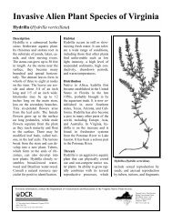
FIGURE <strong>3.09</strong> - 1<br />
<strong>Constructed</strong> <strong>Stormwater</strong> <strong>Wetland</strong>s - Plan<br />
FIGURE <strong>3.09</strong> - 2<br />
<strong>Constructed</strong> <strong>Stormwater</strong> <strong>Wetland</strong>s - Depth Zones<br />
<strong>3.09</strong> - 16
MINIMUM STANDARD <strong>3.09</strong> CHAPTER 3<br />
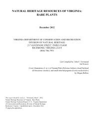
FIGURE <strong>3.09</strong> - 3<br />
Dry Weather and Wet Weather Flow Paths<br />
<strong>3.09</strong> - 17
MINIMUM STANDARD <strong>3.09</strong> CHAPTER 3<br />
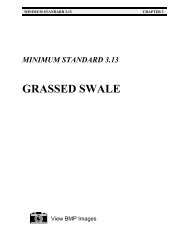
FIGURE <strong>3.09</strong> - 4<br />
Off-line Bypass Structure<br />
<strong>3.09</strong> - 18
MINIMUM STANDARD <strong>3.09</strong> CHAPTER 3<br />
REFERENCES<br />
Chesapeake Bay Local Assistance Department (CBLAD). Local Assistance Manual: A Guide for<br />
the Development of Local Programs in Order to Comply with the Chesapeake Bay<br />
Preservation Act. Richmond, <strong>Virginia</strong>: November 1989.<br />
Galli, J. Analysis of Urban BMP Performance and Longevity in Prince George’s County,<br />
Maryland. Washington, D.C.: Metropolitan Washington Council of Governments<br />
(MWCOG), August, 1992.<br />
Maryland Department of Natural Resources (Md. DNR), Water Resources Administration.<br />
Guidelines for Constructing <strong>Wetland</strong> <strong>Stormwater</strong> Basins. Annapolis, Maryland: March,<br />
1987.<br />
Maryland Department of Natural Resources (Md. DNR), Water Resources Administration. <strong>Wetland</strong><br />
Basins for <strong>Stormwater</strong> Treatment; Discussion and Background. Annapolis, Maryland:<br />
undated.<br />
Northern <strong>Virginia</strong> Planning District Commission (NVPDC). Northern <strong>Virginia</strong> BMP Handbook.<br />
Annandale, <strong>Virginia</strong>: November, 1992.<br />
Schueler, T.R. Design of <strong>Stormwater</strong> <strong>Wetland</strong> Systems: Guidelines for Creating Diverse and<br />
Effective <strong>Stormwater</strong> <strong>Wetland</strong> Systems in the Mid-Atlantic Region. Washington, D.C.:<br />
Metropolitan Washington Council of Governments (MWCOG), October, 1992.<br />
Schueler, T.R., P.A. Kumble, and M.A. Heraty. A Current Assessment of Urban Best Management<br />
Practices. Washington, D.C.: Metropolitan Washington Council of Governments<br />
(MWCOG), March 1992.<br />
Schueler, T. R. Controlling Urban Runoff: A Practical Manual for Planning and Designing Urban<br />
BMPs. Washington, D.C.: Metropolitan Washington Council of Governments (MWCOG),<br />
July, 1987.<br />
<strong>Virginia</strong> Department of Conservation and Recreation (DCR). <strong>Virginia</strong> Erosion and Sediment<br />
Control Handbook (VESCH). 3rd ed. Richmond, <strong>Virginia</strong>: 1992.<br />
Washington State Department of Ecology. <strong>Stormwater</strong> Management Manual for the Puget Sound<br />
Basin (The Technical Manual). Olympia, Washington: February, 1992.<br />
<strong>3.09</strong> - 19
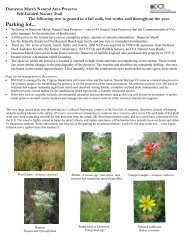
Chapter <strong>3.09</strong><br />
<strong>Constructed</strong> <strong>Stormwater</strong> <strong>Wetland</strong> – recently completed.<br />
<strong>Constructed</strong> <strong>Stormwater</strong> <strong>Wetland</strong> – becoming stabilized, emergent<br />
vegetation barely visible.<br />
<strong>Constructed</strong> <strong>Stormwater</strong> <strong>Wetland</strong>
Chapter <strong>3.09</strong><br />
<strong>Constructed</strong> <strong>Stormwater</strong> <strong>Wetland</strong>. Note vegetation protected from<br />
waterfowl by netting system.<br />
Forebay and <strong>Constructed</strong> <strong>Stormwater</strong> <strong>Wetland</strong> incorporated into<br />
regional retention basin design.<br />
<strong>Constructed</strong> <strong>Stormwater</strong> <strong>Wetland</strong>