Terugmeldkop T.VIS – AS-Interface Control Module T ... - ExtraNet
Terugmeldkop T.VIS – AS-Interface Control Module T ... - ExtraNet
Terugmeldkop T.VIS – AS-Interface Control Module T ... - ExtraNet

Create successful ePaper yourself
Turn your PDF publications into a flip-book with our unique Google optimized e-Paper software.
Process Equipment<br />
Division<br />
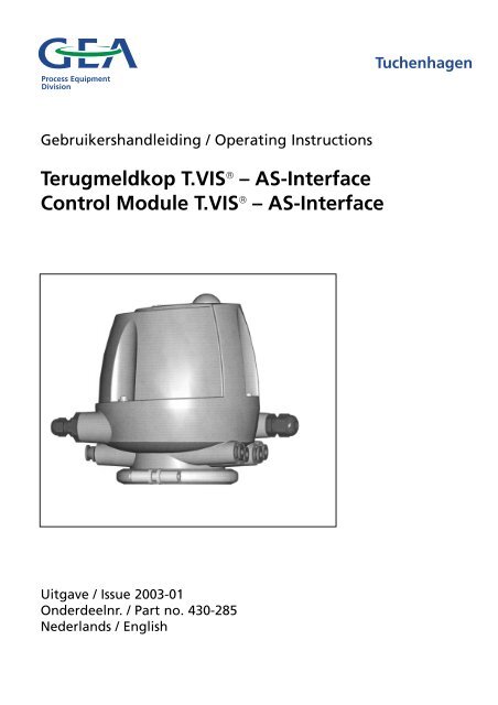
Gebruikershandleiding / Operating Instructions<br />
<strong>Terugmeldkop</strong> T.VIS ® <strong>–</strong> <strong>AS</strong>-<strong>Interface</strong><br />
<strong>Control</strong> <strong>Module</strong> T.VIS ® <strong>–</strong> <strong>AS</strong>-<strong>Interface</strong><br />
Uitgave / Issue 2003-01<br />
Onderdeelnr. / Part no. 430-285<br />
Nederlands / English<br />
Tuchenhagen
Inhoudsopgave<br />
Veiligheidsinstructies .............................................. 2<br />
Toepassing............................................................ 2<br />
Personeel.............................................................. 2<br />
Aanpassingen, reserve onderdelen, toebehoren 2<br />
Algemene voorschriften...................................... 2<br />
Waarschuwingssymbolen in de<br />
gebruikershandleiding ........................................ 3<br />
Overige symbolen................................................ 3<br />
Toepassing .............................................................. 4<br />
Funtie........................................................................ 6<br />
Communicatie module ........................................ 7<br />
Sensormodule .................................................... 11<br />
SET-UP Jumper .................................................. 12<br />
RESET-Funktie .................................................... 12<br />
Transport en opslag .............................................. 12<br />
Ontwerp ................................................................ 13<br />
Inbouwpositie ....................................................14<br />
Pneumatische aansluitingen ................................ 14<br />
Luchtslang monteren ........................................ 14<br />
Stuurlucht aansluitingen .................................. 15<br />
Electrische aansluitingen ...................................... 16<br />
<strong>AS</strong>I aansluitingen .............................................. 16<br />
Externe naderingsschakelaar .......................... 17<br />
In gebruikname...................................................... 18<br />
Stap 1 <strong>–</strong> Stuurlucht ............................................ 18<br />
Stap 2 <strong>–</strong> aansturing ventiel................................ 18<br />
Stap 3 <strong>–</strong> Voltage ................................................ 18<br />
Stap 4.1 <strong>–</strong> Instellen externe naderingsschakelaar<br />
in lantaarn voor dubbelklep in onbalans 19<br />
Stap 4.2 <strong>–</strong> Instellen externe naderingsschakelaar<br />
in lantaarn voor dubbelklep in balans .... 20<br />
Stap 5 <strong>–</strong> SET-UP .................................................. 21<br />
Stap 6 <strong>–</strong> Jumper verwijderen ............................ 22<br />
Stap 7 <strong>–</strong> Adressering .......................................... 22<br />
Onderhoud ............................................................ 23<br />
Inspecties............................................................ 23<br />
Storing, oorzaak, oplossing .............................. 24<br />
Demontage ........................................................ 28<br />
Montage op VARIVENT ® -Ventiel ...................... 34<br />
Montage op vlinderklep.................................... 35<br />
Montage op ECOVENT ® -Ventiel........................ 36<br />
Communicatie module <strong>AS</strong>-<strong>Interface</strong> .................... 37<br />
Functieomschrijving van de aansluitingen........37<br />
Aansluitschema.................................................. 38<br />
Aansluitschema terugmeldkop T.VIS .................. 39<br />
Technische gegevens ............................................ 40<br />
Algemeen .......................................................... 40<br />
Apparatuur ........................................................ 40<br />
Specificatie voor de <strong>AS</strong>I communicatiemodule<br />
.............................................................. 41<br />
Gereedschapslijst .............................................. 42<br />
Bijlagen<br />
Afmetingen blad<br />
Reserve onderdelen lijst<br />
Contents<br />
Safety Instructions .................................................. 2<br />
Designated use .................................................... 2<br />
Personnel.............................................................. 2<br />
Modifications, spare parts, accessories .............. 2<br />
General instructions ............................................ 2<br />
Marking of safety instructions in the<br />
operating manual................................................ 3<br />
Further symbols.................................................... 3<br />
Designated Use ...................................................... 4<br />
Function.................................................................... 6<br />
Communication module...................................... 7<br />
Sensor module .................................................. 11<br />
SET-UP Jumper .................................................. 12<br />
RESET-Function .................................................. 12<br />
Transport and Storage .......................................... 12<br />
Design .................................................................... 13<br />
Installation position............................................14<br />
Pneumatic Connections ........................................ 14<br />
Installing the air hose........................................ 14<br />
<strong>Control</strong> air connections .................................... 15<br />
Electrical Connections .......................................... 16<br />
Connection <strong>AS</strong>I .................................................. 16<br />
Externer proximity switch ................................ 17<br />
Commissioning ...................................................... 18<br />
Step 1 <strong>–</strong> <strong>Control</strong> air............................................ 18<br />
Step 2 <strong>–</strong> Valve actuation.................................... 18<br />
Step 3 <strong>–</strong> Voltage ................................................ 18<br />
Step 4.1 <strong>–</strong> Adjust external proximity switch<br />
in the lantern for unbalanced double-disk...... 19<br />
Step 4.2 <strong>–</strong> Adjust external proximity switch<br />
in the lantern for balanced double-disk .......... 20<br />
Step 5 <strong>–</strong> SET-UP .................................................. 21<br />
Step 6 <strong>–</strong> Removing the jumper.......................... 22<br />
Step 7 <strong>–</strong> Addressing .......................................... 22<br />
Maintenance .......................................................... 23<br />
Inspections.......................................................... 23<br />
Malfunction, Cause, Remedy ............................ 26<br />
Dismantling........................................................ 28<br />
Mounting on to VARIVENT ® valve .................... 34<br />
Mounting on to butterfly valve........................ 35<br />
Mounting on to ECOVENT ® valve .................... 36<br />
Communication module <strong>AS</strong>-<strong>Interface</strong> .................. 37<br />
Functional description of the terminals ............37<br />
Wiring diagram.................................................. 38<br />
Wiring scheme, <strong>Control</strong> <strong>Module</strong> T.VIS ................ 39<br />
Technical Data ........................................................ 40<br />
General .............................................................. 40<br />
Equipment.......................................................... 40<br />
Specification for the <strong>AS</strong>I communication<br />
module .............................................................. 41<br />
List of Tools ........................................................ 42<br />
Annex<br />
Dimension sheet<br />
Spare parts lists<br />
2003-01 · <strong>Terugmeldkop</strong> T.VIS <strong>–</strong> <strong>AS</strong>-<strong>Interface</strong> / <strong>Control</strong> <strong>Module</strong> T.VIS <strong>–</strong> <strong>AS</strong>-<strong>Interface</strong> 1
Veiligheidsinstructies<br />
Toepassing<br />
De terugmeldkop T.VIS <strong>–</strong> <strong>AS</strong>-<strong>Interface</strong> (<strong>AS</strong>I) is alleen<br />
ontworpen om te gebruiken als hieronder beschreven<br />
wordt. Iedere andere manier van gebruik is ten strengste<br />
verboden. Tuchenhagen kan niet verantwoordelijk<br />
gehouden worden voor schade of letsel door oneigenlijk<br />
gebruik. Het risico ligt geheel bij de gebruiker.<br />
Om een goede werking van de terugmeldkop te garanderen,<br />
moet deze juist worden vervoerd en opge-slagen,<br />
alsook vakkundig worden gemonteerd en ge-installeerd.<br />
Voor een juist gebruik moeten ook de gebruiks-, inspectie-<br />
en onderhoudshandleidingen gelezen en begrepen<br />
worden.<br />
Personeel<br />
Personeel belast met het gebruik en onderhoud van de<br />
terugmeldkop moet hiervoor bevoegd en ter zake kundig<br />
zijn. Zij moeten ge-informeerd zijn over mogelijke<br />
gevaren en de veiligheidsinstructies in betreffende<br />
handleiding gelezen en begrepen hebben. Werk aan de<br />
electrische aansluitingen mag alleen door electrotechnisch<br />
vakpersoneel gedaan worden.<br />
Aanpassingen, reserve<br />
onderdelen, toebehoren<br />
Eigenhandige aanpassingen of veranderingen die de<br />
veiligheid van de terugmeldkop be-invloeden zijn verboden.<br />
Veiligheidsmaatregelen mogen niet omzeilt, verwijderd<br />
of uitgeschakeld worden.<br />
Alleen orginele reserve onderdelen geleverd door de<br />
fabrikant mogen gebruikt worden.<br />
Algemene voorschriften<br />
De gebruiker is verplicht om de terugmeldkop alleen<br />
dan te gebruiken wanneer deze helemaal in goede staat<br />
is.<br />
Naast de instructies in de handleiding gelden de onderstaande<br />
maatregelen:<br />
<strong>–</strong> relevante ongelukpreventie regels<br />
<strong>–</strong> algemeen erkende veiligheidsregels<br />
<strong>–</strong> nationale regels voor het land van gebruik<br />
<strong>–</strong> interne werk- en veiligheidsregels op de werkplaats.<br />
2<br />
Safety Instructions<br />
Designated use<br />
The <strong>Control</strong> <strong>Module</strong> T.VIS <strong>–</strong> <strong>AS</strong>-<strong>Interface</strong> (<strong>AS</strong>I) is<br />
designed exclusively for the purposes described below.<br />
Using the control module for purposes other than those<br />
mentioned is considered contrary to its designated use.<br />
Tuchenhagen cannot be held liable for any damage<br />
resulting from such use; the risk of such misuse lies<br />
entirely with the user.<br />
The prerequisite for the reliable and safe operation of<br />
the control module is proper transportation and storage<br />
as well as competent assembly.<br />
Operating the control module within the limits of its<br />
designated use also involves observing the operating,<br />
inspection and maintenance instructions.<br />
Personnel<br />
Personnel entrusted with the operation and maintenance<br />
of the control module must have the suitable<br />
qualification to carry out their tasks. They must be<br />
informed about possible dangers and must understand<br />
and observe the safety instructions given in the relevant<br />
manual. Only allow qualified personnel to make<br />
electrical connections.<br />
Modifications, spare parts,<br />
accessories<br />
Unauthorized modifications, additions or conversions<br />
which affect the safety of the control module are not<br />
permitted. Safety devices must not be bypassed,<br />
removed or made inactive.<br />
Only use original spare parts and accessories admitted<br />
by the manufacturer.<br />
General instructions<br />
The user is obliged to operate the control module only<br />
when it is in good working order.<br />
In addition to the instructions given in the operating<br />
manual, please observe the following:<br />
<strong>–</strong> relevant accident prevention regulations<br />
<strong>–</strong> generally accepted safety regulations<br />
<strong>–</strong> regulations effective in the country of installation<br />
<strong>–</strong> working and safety instructions effective in the user's<br />
plant.<br />
2003-01 · terugmeldkop T.VIS <strong>–</strong> <strong>AS</strong>-<strong>Interface</strong> / <strong>Control</strong> <strong>Module</strong> T.VIS <strong>–</strong> <strong>AS</strong>-<strong>Interface</strong>
Waarschuwingssymbolen<br />
in de<br />
gebruikershandleiding<br />
Bepaalde instructies in de handleiding hebben speciale<br />
aandacht nodig. Zij worden vooraf gegaan door onderstaande<br />
symbolen en bijbehorende signaalwoorden.<br />
Het is van groot belang dat men de tekst naast deze<br />
symbolen eerst goed leest alvorens door te gaan met het<br />
lezen van de instructies voor montage en gebruik van<br />
het ventiel.<br />
Symbool Signaalwoord Verklaring<br />
GEVAAR Direct gevaar met kans op<br />
zware lichamelijke verwon<br />
-dingen of de dood tot<br />
gevolg.<br />
LET OP Gevaarlijke situatie met<br />
kans op lichte lichamelijke<br />
verwondingen en/of scha-<br />
de aan het materiaal.<br />
P<strong>AS</strong> OP Gevaar door electriciteit<br />
Overige symbolen<br />
Symbool Verklaring<br />
• Proces / gebruiksstappen welk in<br />
de gegeven volgorde moeten<br />
worden doorlopen.<br />
✗ Informatie om tot een optimale werking<br />
van de terugmeldkop te komen.<br />
<strong>–</strong> Algemene opsomming<br />
2003-01 · <strong>Terugmeldkop</strong> T.VIS <strong>–</strong> <strong>AS</strong>-<strong>Interface</strong> / <strong>Control</strong> <strong>Module</strong> T.VIS <strong>–</strong> <strong>AS</strong>-<strong>Interface</strong><br />
Marking of safety<br />
instructions in the<br />
operating manual<br />
Special safety instructions are given directly before the<br />
operating instructions. They are marked by the following<br />
symbols and associated signal words.<br />
It is essential that you read and observe the texts belonging<br />
to these symbols before you continue reading the<br />
instructions and handling the control module.<br />
Symbol Signal word Meaning<br />
DANGER Imminent danger, which<br />
may cause severe bodily<br />
injury or death.<br />
CAUTION Dangerous situation,<br />
which may cause slight<br />
injury or damage to<br />
material.<br />
ATTENTION Danger from electrical<br />
power<br />
Further symbols<br />
Symbol Meaning<br />
• Process / operating steps which<br />
must be performed in the specified<br />
order.<br />
✗ Information as to the optimum<br />
use of the control module.<br />
<strong>–</strong> General enumeration<br />
3
Toepassing<br />
Met de terugmeldkop T.VIS ® (Tuchenhagen Ventil<br />
Informations System) met <strong>AS</strong>-<strong>Interface</strong> (<strong>AS</strong>I) worden<br />
alle VARIVENT ® -Procesventielen pneumatisch en elektrisch<br />
aangesloten.<br />
De terugmeldkop T.VIS ® <strong>–</strong> <strong>AS</strong>I bestaat uit<br />
<strong>–</strong> een sensor module voor detectie van de schakel-positie<br />
van het ventiel,<br />
<strong>–</strong> een communicatie module voor het verwerken en versturen<br />
van de data van het ventiel en voor de stroomvoorziening,<br />
<strong>–</strong> tenminste 1 en maximaal 3 pilootventielen voor het<br />
aansturen van de hoofdslag en de liftslagen,<br />
<strong>–</strong> een logic-element NOT (optioneel) als back-up voor de<br />
hoofdveer of voor het aansturen van minder be-langrijke<br />
actuators (lucht/lucht) en<br />
<strong>–</strong> een aansluiting voor een externe naderingsschakelaar<br />
voor controle van de rustpositie van de dubbelklep.<br />
Met T.VIS <strong>–</strong> <strong>AS</strong>I kan op alle ventielen<br />
<strong>–</strong> de ruststand van de ventielklep controleren,<br />
<strong>–</strong> de aangestuurde positie van de ventielklep controleren,<br />
<strong>–</strong> de feedback van de aangestuurde ventielklep instellen<br />
d.m.v. SET-UP,<br />
<strong>–</strong> de stand van het ventiel laten zien m.b.v. verschillende<br />
kleuren licht via een doorzichtig kapje op de kap van<br />
de terugmeldkop.<br />
.<br />
Met T.VIS <strong>–</strong> <strong>AS</strong>I kan daarnaast bij alle dubbelzittingventielen<br />
<strong>–</strong> de aangestuurde positie van de ventielklep tijdens het<br />
liften gecontroleerd worden,<br />
<strong>–</strong> de ruststand en de liftfunctie van de dubbelklep*<br />
gecontroleerd worden,<br />
<strong>–</strong> het liften met de LEFF-functie van de ventiel- en dubbelklep*<br />
uitgevoerd en gecontroleerd worden,<br />
<strong>–</strong> de liftaansturing van de ventiel- en dubbelklep* laten<br />
zien m.b.v. verschillende kleuren licht via een doorzichtig<br />
kapje op de kap van de terugmeldkop.<br />
4<br />
Designated Use<br />
The <strong>Control</strong> <strong>Module</strong> T.VIS ® (Tuchenhagen Valve Information<br />
System)with <strong>AS</strong>-<strong>Interface</strong> (<strong>AS</strong>I) is used for the<br />
pneumatic and electrical connection of VARIVENT ®<br />
process valves.<br />
<strong>Control</strong> <strong>Module</strong> T.VIS ® <strong>–</strong> <strong>AS</strong>I consists of<br />
<strong>–</strong> a sensor module for the detection of the valve`s<br />
switching position,<br />
<strong>–</strong> a communication module for the evaluation and transmission<br />
of valve data and for the power supply,<br />
<strong>–</strong> at least one or three solenoid valves maximum for the<br />
actuation of the main stroke and the lift strokes,<br />
<strong>–</strong> a logic element NOT (optional) for backup of the valve`s<br />
main spring or for the actuation of indifferent<br />
actuators (air/air) and<br />
<strong>–</strong> a connection for an external proximity switch for<br />
monitoring the non-actuated position of the doubledisk<br />
T.VIS <strong>–</strong> <strong>AS</strong>I allows on all valves<br />
<strong>–</strong> monitoring the non-actuated position of the valve disk,<br />
<strong>–</strong> monitoring the actuated position of the valve disk,<br />
<strong>–</strong> setting of the actuated position feedback of the valve<br />
disk using SET-UP,<br />
<strong>–</strong> coloured visualisation of the valve position and status<br />
via the luminous cap fixed on the control module<br />
T.VIS <strong>–</strong> <strong>AS</strong>I allows in addition on all doubleseat<br />
valves<br />
<strong>–</strong> monitoring the actuated position of the valve disk<br />
during the lift operation<br />
<strong>–</strong> monitoring the non-actuated position and the lift<br />
function of the double-disk*<br />
<strong>–</strong> lifting and monitoring of the valve disk and doubledisk*<br />
using the LEFF function,<br />
<strong>–</strong> coloured visualisation of the lift actuation of the valve<br />
disk and double-disk * via the luminous cap fixed on<br />
the control module,<br />
2003-01 · <strong>Terugmeldkop</strong> T.VIS <strong>–</strong> <strong>AS</strong>-<strong>Interface</strong> / <strong>Control</strong> <strong>Module</strong> T.VIS <strong>–</strong> <strong>AS</strong>-<strong>Interface</strong>
Met T.VIS-<strong>AS</strong>I en Palm PC inclusief Tuchenhagen-Software<br />
zijn de volgende ventieldata<br />
zichtbaar te maken op de Palm:<br />
<strong>–</strong> de ingestelde ventielconfiguratie kan uitgelezen en<br />
naar behoefte veranderd worden,<br />
<strong>–</strong> de door SET_UP ingestelde positie (tussen 0 en 80<br />
mm) voor de ruststand en de aangestuurde stand van<br />
de ventielklep en de aangestuurde stand van de ventielklep-liftslag<br />
(alleen bij ventielen met lift) kan worden<br />
uitgelezen,<br />
<strong>–</strong> de tijdduur dat het ventiel in ruststand of aangestuurde<br />
stand staat kan uitgelezen worden,<br />
<strong>–</strong> de maximale en minimale positie van het ventiel in<br />
ruststand en in aangestuurde stand kan uitgelezen<br />
worden,<br />
<strong>–</strong> de “in bedrijf” tijd, het aantal hoofdslagen, de ingestelde<br />
onderhoudsinterval en de berekende tijd tot het<br />
eerstvolgende onderhoud (Onderhoudsinterval minus<br />
“in bedrijf” tijd) kunnen uitgelezen worden,<br />
<strong>–</strong> de lengte van de hoofdslag en de ventielklep-liftslag<br />
kan vastgesteld worden,<br />
<strong>–</strong> het feedbacksignaal van de output kan gecontroleerd<br />
worden,<br />
<strong>–</strong> de opgeslagen foutmeldingen in het foutmeldings-logboek<br />
kunnen uitgelezen worden.<br />
* De controle van de functie van de dubbelklep is alleen mogelijk met<br />
een externe naderingsschakelaar. Zonder deze kan alleen de<br />
besturing van dubbelklep aangegeven worden.<br />
2003-01 · <strong>Terugmeldkop</strong> T.VIS <strong>–</strong> <strong>AS</strong>-<strong>Interface</strong> / <strong>Control</strong> <strong>Module</strong> T.VIS <strong>–</strong> <strong>AS</strong>-<strong>Interface</strong><br />
T.VIS-<strong>AS</strong>I and Palm PC, incl. Tuchenhagen<br />
software allows the visualisation of the<br />
following valve data in the Palm:<br />
<strong>–</strong> the preset valve configuration can be read out and<br />
modified, if required<br />
<strong>–</strong> reading-out the position of the non-actuated valve<br />
disk (between 0 and 80mm) and the actuated valve<br />
disk (main stroke) ascertained by SET-UP as well as<br />
the actuated valve disk lift-stroke (for lift-valves only),<br />
<strong>–</strong> reading-out the duration of the actuated and nonactuated<br />
valve position,<br />
<strong>–</strong> reading-out the maximum and minimum position of<br />
the actuated and non-actuated valve,<br />
<strong>–</strong> reading-out the operating time, the number of main<br />
strokes, the preset maintenance interval and the calculated<br />
period until maintenance is indicated (maintenance<br />
interval less operating time),<br />
<strong>–</strong> the stroke length for the main stroke and the valve<br />
disk lift-stroke can be ascertained,<br />
<strong>–</strong> checking the feedback signal outputs,<br />
<strong>–</strong> reading-out the stored error messages from an error<br />
log.<br />
* Function monitoring of the double-disk is possible by an external<br />
proximity switch located in the lantern. If this external prox. is not<br />
provided, only actuation of the double-disk will be indicated.<br />
5
Functie<br />
In de terugmeldkop bevinden zich pneumatische en<br />
electrische modules.<br />
De pneumatische modules zijn pilootventielen, waarvan<br />
het aantal, afhankelijk van het gebruik, kan varieren<br />
tussen 1 en 3 stuks.<br />
Een Logic-element NOT kan ingezet worden voor persluchtondersteuning<br />
voor de actuatorveer. De stuurlucht<br />
wordt aanvoert naar de relevante stuurlucht-kamers via<br />
aansluitingen aan de buitenkant van de terugmeldkop.<br />
VARIVENT ® -Ventielen worden van stuurlucht voorzien<br />
via de schakelstang en een extra aansluiting voor de<br />
hoofdactuator waarmee ECOVENT ® - en vlinderklepactuators<br />
aangesloten kunnen worden. De afgevoerde<br />
lucht van de pilootventielen wordt verzameld en afgevoerd<br />
via een luchtaansluiting.<br />
Bij de electronische modules gaat het om een sensormodule,<br />
welke de sensortechniek bevat voor de positiebepaling<br />
van het ventiel en een commmunicatie-module,<br />
waarin zich de logic control voor de uitwisseling van<br />
gegevens volgens <strong>AS</strong>I-specificatie 2.11 met het hoofd<br />
controlesysteem bevindt.<br />
De belangrijkste taak van deze electronische modules is<br />
het bepalen van de ventielstand op basis van de stand<br />
van de klepsteel en de feedback hiervan naar het hoofd<br />
controlesysteem te sturen.<br />
Verdere zaken zijn het automatisch detecteren van alle<br />
bestaande besturingsposities van het ventiel tijdens de<br />
SET-UP procedure alsook foutdiagnose, data verzamelen<br />
en het bepalen van het tijdstip van onderhoud. Alle<br />
gegenereerde data kan op elk gewenst moment uitgelezen<br />
worden met een commercieel voorhanden zijnde<br />
Palm via een speciaal hiervoor ingebouwde COM-interface.<br />
Dankzij het doorzichtige kapje op de kap van de terugmeldkop<br />
is het mogelijk om de LED’s (light emmitting<br />
diodes), welke op de communicatie module zijn<br />
geplaatst, ook te zien als de kap gesloten is. De drie<br />
LED’s in verschillende kleuren geven alle hoofdfuncties<br />
van het ventiel aan:<br />
<strong>–</strong> ventiel in ruststand <strong>–</strong> groen<br />
<strong>–</strong> ventiel in bestuurde stand <strong>–</strong> geel<br />
<strong>–</strong> ventielklep gelift <strong>–</strong> geel/groen langzaam knipperend<br />
<strong>–</strong> dubbelklep gelift <strong>–</strong> geel/groen langzaam knipperend<br />
<strong>–</strong> liften met LEFF-Functie actief <strong>–</strong> geel/groen snel knipperend<br />
<strong>–</strong> ventielstoring <strong>–</strong> rood<br />
<strong>–</strong> onderhoud nodig <strong>–</strong> rood knipperend<br />
<strong>–</strong> ventiel doet niets <strong>–</strong> geen indicatie<br />
Dankzij het eenvoudige Plug and Play systeem is het op<br />
elk moment mogelijk om in geval van storing de commu-nicatie<br />
module te vervangen.<br />
6<br />
Function<br />
Pneumatic and electronic modules are located inside<br />
the control module.<br />
The pneumatic modules are in this case solenoid valves,<br />
the number of which varies between 1 and 3, depending<br />
on their use.<br />
The logic element NOT is used for pressure backup of<br />
the actuator spring. <strong>Control</strong> air is supplied to the relevant<br />
control air chambers via air connections at the outside<br />
of the control module.<br />
VARIVENT ® valves are supplied with main control air<br />
via the switch bar and an additional external air<br />
connection for the main actuator that allows for the<br />
connection of the actuator for ECOVENT ® valves and<br />
butterfly valves. Exhaust air of the solenoid valves is<br />
collected and evacuated via an air connection.<br />
The already mentioned electronic module comprises a<br />
sensor module that contains the necessary sensor technology<br />
for the determination of the valve position and a<br />
communication module with logic control for data<br />
exchange with the master control system as per <strong>AS</strong>I-specification<br />
2.11.<br />
The main task of these electronic modules is to determine<br />
the valve position on the basis of the valve stem<br />
position and to generate for this position the corresponding<br />
feedback signals and send them to the master<br />
control system.<br />
Other tasks are the automatic detection of the actuated<br />
position for all existing actuated positions of the valve<br />
during the SET-UP procedure as well as error diagnosis,<br />
data log and the generation of a demand for maintenance.<br />
All generated data can be read out at any time<br />
via an especially provided COM interface using a<br />
commercially available Palm.<br />
The illuminated cap integrated into the hood of the control<br />
module, allows the visualisation of the light emitting<br />
diodes (LED) arranged on the communication<br />
module, even if the hood is closed.<br />
The three differently coloured LEDs indicate all main<br />
functions of the valve:<br />
<strong>–</strong> non-actuated valve position <strong>–</strong> green<br />
<strong>–</strong> actuated valve position <strong>–</strong> yellow<br />
<strong>–</strong> valve disk lifted <strong>–</strong> yellow/green slow flashing<br />
<strong>–</strong> double-disk lifted <strong>–</strong> yellow/green slow flashing<br />
<strong>–</strong> Lifting with LEFF function active <strong>–</strong> yellow/green<br />
quick flashing<br />
<strong>–</strong> valve error <strong>–</strong> red<br />
<strong>–</strong> demand for maintenance <strong>–</strong> red flashing<br />
<strong>–</strong> valve idle <strong>–</strong> no indication<br />
The easy Plug-and-Play method allows at any time to<br />
change the communication module by a bus module in<br />
case of failure.<br />
2003-01 · <strong>Terugmeldkop</strong> T.VIS <strong>–</strong> <strong>AS</strong>-<strong>Interface</strong> / <strong>Control</strong> <strong>Module</strong> T.VIS <strong>–</strong> <strong>AS</strong>-<strong>Interface</strong>
Communicatie module Communication <strong>Module</strong><br />
LED G<br />
LED H<br />
LED D<br />
LED E<br />
1<br />
2<br />
3<br />
4<br />
5<br />
6<br />
7<br />
8<br />
9<br />
10<br />
11<br />
12<br />
13<br />
14<br />
15<br />
16<br />
LED A<br />
LED F<br />
Externe bedienings- en indicatieelementen<br />
Lichtdiode A (LED A)<br />
Kleur: Groen<br />
Melding: Constant brandend<br />
⇒ Ventiel in startpositie (ruststand)<br />
⇒ Inschakelen T.VIS <strong>–</strong> <strong>AS</strong>-<strong>Interface</strong><br />
3 s rood, wisselt naar groen <strong>–</strong> constant<br />
brandend<br />
Knipperend<br />
⇒ Ventielstang beweegt zich naar de<br />
startpositie<br />
Knippert langzaam en regelmatig om<br />
en om met lichtdiode B (geel)<br />
⇒ Liftactuator ventielklep of dubbelklep<br />
wordt aangestuurd (alleen met ext.<br />
naderingsschakelaar)<br />
Knippert snel en onregelmatig om en<br />
om het lichtdiode B (geel)<br />
⇒ liftactuator voor ventielklep of dubbelklep<br />
met LEFF-Funktion<br />
Knippert snel om en om met lichtdiode<br />
C (rood): 3 s LED A (groen) en<br />
1 s LED C (rood)<br />
⇒ Ventiel in startpositie en ventiel behoeft<br />
onderhoud.<br />
LED B<br />
PILOT ERROR<br />
SL<br />
Profile<br />
Solenoid 1<br />
Solenoid 2<br />
Solenoid 3<br />
LEFF Y2<br />
LEFF Y3<br />
ext. prox.<br />
SET-UP/RESET<br />
<strong>AS</strong>I-BUS<br />
4 PWR<br />
7 FAULT<br />
11 SEATLIFT PROX+<br />
12 SEATLIFT PROX−<br />
13 COMMON JUMPER<br />
14 SET-UP JUMPER<br />
15 <strong>AS</strong>I (+)<br />
16<br />
COM<br />
<strong>AS</strong>I (−)<br />
2003-01 · <strong>Terugmeldkop</strong> T.VIS <strong>–</strong> <strong>AS</strong>-<strong>Interface</strong> / <strong>Control</strong> <strong>Module</strong> T.VIS <strong>–</strong> <strong>AS</strong>-<strong>Interface</strong><br />
LED C<br />
External operating and display<br />
elements<br />
Light emitting diode A (LED A)<br />
Colour: green<br />
Indication: Permanent light<br />
⇒ Valve in start position (non-actuated)<br />
⇒ switching on T.VIS <strong>–</strong> <strong>AS</strong>-<strong>Interface</strong><br />
3 s red, changes to green <strong>–</strong> permanent<br />
light<br />
Flashing<br />
⇒ Valve stem moves towards start position<br />
Slow regular flashing in turn with light<br />
emitting diode B (yellow)<br />
⇒ Lifting actuator actuated for valve disk<br />
or double disk (only with external prox.)<br />
Quick irregular flashing in turn with<br />
light emitting diode B (yellow)<br />
⇒ Lifting actuator for valve disk or double<br />
disk with LEFF function<br />
Quick flashing in turn with light emitting<br />
diode C (red): 3 s LED A (green) and<br />
1 s LED C (red)<br />
⇒ Valve in start position and valve<br />
maintenance cycle reached<br />
7
Lichtdiode B (LED B)<br />
Kleur: geel<br />
Melding: constant brandend<br />
⇒ Ventiel in eindstand<br />
(aangestuurde positie)<br />
Knipperend<br />
⇒ klepsteel beweegt zich naar de<br />
eindstand<br />
Knippert langzaam en regelmatig om<br />
en om met lichtdiode A (groen)<br />
⇒ Liftactuator ventielklep of dubbelklep<br />
wordt aangestuurd (alleen met ext.<br />
naderingsschakelaar)<br />
Knippert snel en onregelmatig om en<br />
om het lichtdiode A (groen)<br />
⇒ liftactuator voor ventielklep of dubbelklep<br />
met LEFF-functie<br />
Lichtdiode C (LED C)<br />
8<br />
Knippert om en om met lichtdiode C<br />
(rood): 3 s LED B (geel) en<br />
1 s LED C (rood)<br />
⇒ Ventiel in eindstand en behoeft<br />
onderhoud.<br />
Kleur: rood<br />
Melding: Constant brandend<br />
⇒ Ventielstoring of ventiel in<br />
SET-UP functie<br />
Knippert om en om met<br />
Lichtdiode A (groen) of<br />
Lichtdiode B (geel)<br />
⇒ Ventiel behoeft onderhoud<br />
Knippert periodiek 3 maal<br />
⇒ Configuratie of SET-UP nodig<br />
Interne bedienings- en indicatieelementen<br />
Lichtdiode D (LED D)<br />
Kleur: groen<br />
Betekenis: PILOT<br />
Melding: Constant brandend<br />
⇒ Pilootventiel wordt aangestuurd<br />
Lichtdiode E (LED E)<br />
Kleur: geel<br />
Betekenis: SL<br />
Melding: Constant brandend<br />
⇒ Liftpositie bereikt<br />
(alleen met externe naderingsschakelaar)<br />
Light emitting diode B (LED B)<br />
Colour: yellow<br />
Indication: Permanent light<br />
⇒ actuated valve position<br />
Flashing<br />
⇒ Valve stem moves towards actuated<br />
position<br />
Slow regular flashing in turn with light<br />
emitting diode A (green)<br />
⇒ Lifting actuator actuated for valve disk<br />
or double disk (only with external prox.)<br />
Quick irregular flashing in turn with<br />
light emitting diode A (green)<br />
⇒ Lifting actuator for valve disk or<br />
double disk with LEFF function<br />
Quick flashing in turn with light emitting<br />
diode C (red): 3 s LED B (yellow)<br />
and 1 s LED C (red)<br />
⇒ Valve in actuated position<br />
and valve maintenance cycle reached<br />
Light emitting diode C (LED C)<br />
Colour: red<br />
Indication: Permanent light<br />
⇒ Valve error or valve in<br />
SET-UP function<br />
Quick flashing in turn with<br />
light emitting diode A (green) or<br />
light emitting B (yellow)<br />
⇒ Valve maintenance cycle reached<br />
Flashing for 3 times periodically<br />
⇒ Configuration or SET-UP required<br />
Internal operating and display<br />
elements<br />
Light emitting diode D (LED D)<br />
Colour: green<br />
Designation: PILOT<br />
Indication: Permanent light<br />
⇒ Solenoid valve actuated<br />
Light emitting diode E (LED E)<br />
Colour: yellow<br />
Designation: SL<br />
Indication: Permanent light<br />
⇒ Lift position reached<br />
(only with external prox.)<br />
2003-01 · <strong>Terugmeldkop</strong> T.VIS <strong>–</strong> <strong>AS</strong>-<strong>Interface</strong> / <strong>Control</strong> <strong>Module</strong> T.VIS <strong>–</strong> <strong>AS</strong>-<strong>Interface</strong>
LED G<br />
LED H<br />
Lichtdiode F<br />
LED D<br />
LED E<br />
1<br />
2<br />
3<br />
4<br />
5<br />
6<br />
7<br />
8<br />
9<br />
10<br />
11<br />
12<br />
13<br />
14<br />
15<br />
16<br />
LED A<br />
LED F<br />
PILOT ERROR<br />
SL<br />
kleur: rood<br />
Betekenis: FOUT<br />
Meldung: Constant brandend ⇒ Hardwarefout<br />
Knipperend - periodiek<br />
⇒ Softwarefout<br />
⇒ Configuratie of SET-UP nodig<br />
Knipperd periodiek 3 maal<br />
⇒ Configuratie of SET-UP nodig<br />
Lichtdiode G<br />
Kleur: groen<br />
Betekenis: <strong>AS</strong>I Power<br />
Melding: constant brandend ⇒ Stroom aan<br />
Lichtdiode H<br />
Kleur: rood<br />
Betekenis: <strong>AS</strong>I fout<br />
Melding: constant brandend<br />
⇒ geen datauitwisseling<br />
⇒ Adres 0<br />
Knipperend ⇒ randapparatuurstoring<br />
LED B<br />
Profile<br />
Solenoid 1<br />
Solenoid 2<br />
Solenoid 3<br />
LEFF Y2<br />
LEFF Y3<br />
ext. prox.<br />
SET-UP/RESET<br />
<strong>AS</strong>I-BUS<br />
4 PWR<br />
7 FAULT<br />
11 SEATLIFT PROX+<br />
12 SEATLIFT PROX−<br />
13 COMMON JUMPER<br />
14 SET-UP JUMPER<br />
15 <strong>AS</strong>I (+)<br />
16<br />
COM<br />
<strong>AS</strong>I (−)<br />
LED C<br />
2003-01 · <strong>Terugmeldkop</strong> T.VIS <strong>–</strong> <strong>AS</strong>-<strong>Interface</strong> / <strong>Control</strong> <strong>Module</strong> T.VIS <strong>–</strong> <strong>AS</strong>-<strong>Interface</strong><br />
Light emitting diode F<br />
Colour: red<br />
Designation: ERROR<br />
Indication: Permanent light ⇒ Hardware error<br />
Flashing <strong>–</strong> periodically<br />
⇒ Software error<br />
⇒ Configuration or SET-UP required<br />
Flashing for 3 times periodically<br />
⇒ Configuration or SET-UP required<br />
Light emitting diode G<br />
Colour: green<br />
Designation: <strong>AS</strong>I Power<br />
Indication: Permanent light ⇒ Power on<br />
Light emitting diode H<br />
Colour: red<br />
Designation: <strong>AS</strong>I Error<br />
Indication: Permanent light ⇒ no data exchange<br />
⇒Address 0<br />
Flashing ⇒ Error peripherals<br />
9
Taste SET-UP/RESET<br />
Push button SET-UP/RESET<br />
Drukknop<br />
1<br />
2<br />
3<br />
4<br />
5<br />
6<br />
7<br />
8<br />
9<br />
10<br />
11<br />
12<br />
13<br />
14<br />
15<br />
16<br />
Betekenis: SET-UP/RESET<br />
Functie 1 Start SET-UP functie, wanneer jumper<br />
SET-UP (klem 13 en 14) geplaatst is<br />
en<br />
drukknop tenminste 3 s en niet langer dan<br />
7 s ingedrukt wordt.<br />
Functie 2 RESET-Functie, wanneer jumper SET-UP<br />
(klem 13 en 14) niet geplaatst is en<br />
drukknop tenminste 3 s en niet langer dan<br />
7 s ingedrukt wordt.<br />
<strong>Interface</strong> (1)<br />
Functie: <strong>Interface</strong> voor het aansluiten van de<br />
sensormodule<br />
<strong>Interface</strong> (2)<br />
Functie: Seriele interface COM<br />
10<br />
2<br />
PILOT ERROR<br />
SL<br />
SET-UP/RESET<br />
<strong>AS</strong>I-BUS<br />
Profile<br />
Solenoid 1<br />
Solenoid 2<br />
Solenoid 3<br />
LEFF Y2<br />
LEFF Y3<br />
ext. prox.<br />
4 PWR<br />
7 FAULT<br />
11 SEATLIFT PROX+<br />
12 SEATLIFT PROX−<br />
13 COMMON JUMPER<br />
14 SET-UP JUMPER<br />
15 <strong>AS</strong>I (+)<br />
16<br />
COM<br />
<strong>AS</strong>I (−)<br />
Push button<br />
Designation: SET-UP/RESET<br />
Function 1 Start SET-UP function, as soon as jumper<br />
SET-UP is inserted (terminal 13 and 14)<br />
and<br />
push button is pressed at least for 3 s but<br />
no longer than 7 s.<br />
Function 2 RESET function, if jumper SET-UP<br />
(terminal 13 and 14) is not inserted and<br />
push button is pressed at least for 3 s but<br />
no longer than 7 s.<br />
<strong>Interface</strong> (1)<br />
Function: <strong>Interface</strong> for the connection of the sensor<br />
module<br />
<strong>Interface</strong> (2)<br />
Function: Serial interface COM<br />
1<br />
2003-01 · <strong>Terugmeldkop</strong> T.VIS <strong>–</strong> <strong>AS</strong>-<strong>Interface</strong> / <strong>Control</strong> <strong>Module</strong> T.VIS <strong>–</strong> <strong>AS</strong>-<strong>Interface</strong>
Sensormodule Sensor module<br />
Y1<br />
Y2<br />
De Sensormodule bevat het meetelement voor de detectie<br />
van de exacte positie van de klepsteel. Aan de punt<br />
van de klepsteel zit een magneet, waarvan de positie<br />
door het meetelement bepaald kan worden.<br />
Het meetsignaal wordt door de interface (1) door-gegeven<br />
aan de communicatiemodule.<br />
Via dezelfde interface ontvangt de sensormodule de<br />
controle signalen voor de pilootventielen welke de stuurlucht<br />
naar de corresponderende actuators distribueren.<br />
Er kunnen maximaal 3 pilootventielen aangesloten worden,<br />
Waarbij altijd 1 pilootventiel (Y1) voor de hoofdactuator<br />
gereserveerd is.<br />
De aansluitingen voor de pilootventielen (Y1, Y2, Y3)<br />
zijn als stekkerverbinding uitgevoerd, zodat het toevoegen<br />
of wisselen van een pilootventiel eenvoudig is.<br />
LET OP<br />
Het wisselen of toevoegen van een pilootventiel in de<br />
terugmeldkop T.VIS <strong>–</strong> <strong>AS</strong>-<strong>Interface</strong> mag alleen als deze<br />
niet onder spanning staat.<br />
Daarnaast moet, in geval van toevoeging van een pilootventiel<br />
de communicatiemodule worden aangepast.<br />
1<br />
Y3<br />
2003-01 · <strong>Terugmeldkop</strong> T.VIS <strong>–</strong> <strong>AS</strong>-<strong>Interface</strong> / <strong>Control</strong> <strong>Module</strong> T.VIS <strong>–</strong> <strong>AS</strong>-<strong>Interface</strong><br />
The sensor module contains the measuring unit for the<br />
detection of the exact position of the valve stem.<br />
The point of the valve stem is provided with a magnet,<br />
the position of which is detected by the measuring unit.<br />
The measuring signal is transmitted to the communication<br />
module via interface (1).<br />
Via the same interface the sensor module receives the<br />
control signals for the solenoid valves which distribute<br />
the control air to the corresponding actuators.<br />
Up to 3 solenoid valves maximum may be connected<br />
while always one solenoid valve (Y1) must be made<br />
available for the main actuator.<br />
Connectors are used for the connection of the solenoid<br />
valves (Y1, Y2, Y3) so that retro-fitting or replacement of<br />
a solenoid valve is easily done.<br />
CAUTION<br />
Replacement or retro-fitting of solenoid valves to be carried<br />
out only in idle state of the T.VIS <strong>–</strong> <strong>AS</strong>-<strong>Interface</strong><br />
control module.<br />
Take care that in the case of retro-fitting the configuration<br />
of the communication module must be modified.<br />
11
SET-UP jumper<br />
Communicatiemodule T.VIS <strong>–</strong> <strong>AS</strong>I<br />
Communication module T.VIS <strong>–</strong> <strong>AS</strong>I<br />
Transport en<br />
opslag<br />
GEVAAR<br />
Het kunststof van de terugmeldkop is breukgevoelig.<br />
Sla de terugmeldkop op een droge plaats op beschermd<br />
tegen invloeden van buitenaf.<br />
Alvorens deze te gebruiken moet deze tenminste 24 uur<br />
opgeslagen worden op een droge plaats met een temperatuur<br />
van tenminste 5 °C.<br />
12<br />
Jumper<br />
Common<br />
13<br />
14<br />
Jumper niet geplaatst/<br />
Jumper not inserted<br />
SET-UP Funcie niet actief<br />
Hoofd controlesysteem<br />
moet besturing<br />
vrijgeven!<br />
SET-UP Function inactive<br />
Master control system to<br />
release actuations!<br />
RESET-Functie RESET-Function<br />
Communicatiemodule T.VIS <strong>–</strong> <strong>AS</strong>I<br />
Communication module T.VIS <strong>–</strong> <strong>AS</strong>I<br />
Jumper<br />
Common<br />
13<br />
14<br />
Jumper niet geplaatst/<br />
Jumper not inserted<br />
13<br />
14<br />
13<br />
14<br />
RESET-Functie aktief<br />
Na het verhelpen van de storing<br />
wordt de constant brandende<br />
LED C (rood) gereset!<br />
Hiervoor drukknop „SET-UP /<br />
RESET“ min. 3s / max. 7s<br />
indrukken<br />
RESET-Function active<br />
After elimination of the error,<br />
resetting of the error message<br />
permanent light LED C (red).<br />
For this purpose use push<br />
button „SET-UP / RESET“ for<br />
3s min. / 7s max.<br />
Jumper geplaatst/<br />
Jumper inserted<br />
SET-UP Functie aktief<br />
Hoofd controlesysteem<br />
moet besturing<br />
blokkeren!<br />
SET-UP Function active<br />
Master control system to<br />
interlock actuations!<br />
Jumper geplaatst/<br />
Jumper inserted<br />
RESET-Functie niet actief<br />
RESET Function inactive<br />
Transport and<br />
Storage<br />
DANGER<br />
The synthetic materials of the control module is<br />
fragile.<br />
Store the control module in a dry place and protect it<br />
against surrounding conditions.<br />
Prior to any handling, store the module at least for<br />
24 hours in a dry place at a temperature of ≥ 5 °C.<br />
2003-01 · <strong>Terugmeldkop</strong> T.VIS <strong>–</strong> <strong>AS</strong>-<strong>Interface</strong> / <strong>Control</strong> <strong>Module</strong> T.VIS <strong>–</strong> <strong>AS</strong>-<strong>Interface</strong>
Ontwerp<br />
1 Schakelstang<br />
5 Basisplaat<br />
7 Kap<br />
8 Pneumatisch blok<br />
15 Klemring<br />
21 Geluidsdemper<br />
24.4 Aansluiting <strong>AS</strong>I-<br />
BOX<br />
24.3 Aansluiting CLIP-<br />
<strong>AS</strong>I<br />
24.2 Stekker M 12/4polig<br />
26 terugslagklep<br />
43 Sensormodule<br />
47 Communicatiemodule<br />
50 Kabelaansluiting<br />
voor ext. naderingsschakelaar<br />
63 pilootventielen<br />
64 Logic-element NOT<br />
170 Ext.naderingsschak.<br />
LET OP<br />
De permanente magneet<br />
op de schakelstang (1) is<br />
breukgevoelig en moet<br />
beschermd worden tegen<br />
ontlading door stoten.<br />
De magneetvelden kunnen<br />
data verwijderen van<br />
datadragers en kunnen<br />
mechanische componenten<br />
be-invloeden of vernietigen.<br />
7<br />
47<br />
43<br />
170<br />
50<br />
5<br />
15<br />
1<br />
47<br />
2003-01 · <strong>Terugmeldkop</strong> T.VIS <strong>–</strong> <strong>AS</strong>-<strong>Interface</strong> / <strong>Control</strong> <strong>Module</strong> T.VIS <strong>–</strong> <strong>AS</strong>-<strong>Interface</strong><br />
43<br />
8<br />
21 26<br />
8<br />
64<br />
63<br />
24.4<br />
24.3<br />
24.2<br />
63<br />
64<br />
Design<br />
1 Switch bar<br />
5 Base plate<br />
7 Hood<br />
8 Pneumatic block<br />
15 Clamps<br />
21 Sound absorber<br />
24.4 Terminal box <strong>AS</strong>I<br />
24.3 CLIP connection <strong>AS</strong>I<br />
24.2 Plug M 12/4-poles<br />
26 Check valve<br />
43 Sensor module<br />
47 Communication<br />
module<br />
50 Cable gland for<br />
external prox.<br />
63 Solenoid valves<br />
64 Logic element NOT<br />
170 External prox.<br />
CAUTION<br />
The permanent magnet on<br />
the switch bar (1) is fragile<br />
and must therefore be<br />
protected from load resulting<br />
from mechanical<br />
impact.<br />
The magnetic fields can<br />
delete data carriers and<br />
affect or destroy mechanical<br />
components.<br />
13
Inbouw-positie<br />
Standaard<br />
Standaard wordt het ventiel<br />
rechtop ingebouwd.<br />
Ondersteboven<br />
LET OP<br />
Bij ondersteboven inbouwen<br />
vervalt bescherming<br />
IP 65/IP 67, maar geldt IP<br />
55.<br />
Bij ondersteboven inbouwen<br />
van het ventiel:<br />
•Om het mogelijk te maken<br />
om condensaat uit<br />
de terugmeldkop te<br />
laten lopen moet men in<br />
de kap een gat (Ø 10<br />
mm) boren.<br />
(zie detail X)<br />
• Hier een filterplaatje (1),<br />
onderdeelnr. 940-003, in<br />
drukken.<br />
Pneumatische Aansluiting<br />
Luchtslang monteren<br />
14<br />
X<br />
1<br />
Ø10<br />
47<br />
✗Om een goede aansluiting te bewerkstellingen is het<br />
nodig om de pneumatische slang met een slangsnijder<br />
recht af te snijden.<br />
• Perslucht uitzetten.<br />
• Luchtslang in de luchtaansluiting (P) van de terugmeldkop<br />
schuiven.<br />
• Perslucht weer aanzetten.<br />
Detail X / Detail X<br />
Installation<br />
position<br />
Standard<br />
The standard installation<br />
position of the valve is<br />
upright.<br />
Upside down<br />
CAUTION<br />
In case of upside-down<br />
installation, protection<br />
IP 65/IP 67 no longer<br />
applies, but IP 55.<br />
Upside down installation<br />
of the valve:<br />
• To allow the condensation<br />
water to run off<br />
from the control module<br />
a hole (Ø 10 mm) must<br />
be bored into the cap of<br />
the control module<br />
(see detail X)<br />
• Afterwards press in the<br />
filter plate (1),<br />
part no. 940-003.n.<br />
Pneumatic Connections<br />
Installing the air hose<br />
✗To ensure optimum seat in the air connector, the<br />
pneumatic hoses must be cut square with a hose<br />
cutter.<br />
• Shut-off the compressed air supply.<br />
• Push the air hose into the air connector (P) of the<br />
control module.<br />
• Re-open the compressed air supply.<br />
2003-01 · <strong>Terugmeldkop</strong> T.VIS <strong>–</strong> <strong>AS</strong>-<strong>Interface</strong> / <strong>Control</strong> <strong>Module</strong> T.VIS <strong>–</strong> <strong>AS</strong>-<strong>Interface</strong>
Stuurluchtaansluitingen<br />
E1 Afgevoerde lucht<br />
(voor gesloten<br />
luchtafvoer of<br />
geluidsdemper)<br />
E2 Ontluchtingsbeveiliging<br />
(terugslagklep)<br />
<strong>Terugmeldkop</strong> met<br />
1 Pilootventiel<br />
P Centrale luchttoevoer<br />
N Luchtaansluiting voor<br />
backup veerwerking<br />
(alleen met Logicelement<br />
NOT)<br />
Y1 Luchtaansluiting voor<br />
externe hoofdslagaansluiting<br />
(niet benodigd bij<br />
VARIVENT ® -Standaard)<br />
<strong>Terugmeldkop</strong> met<br />
2 Pilootventielen<br />
P Centrale luchttoevoer<br />
N Luchtaansluiting voor<br />
backup veerwerking<br />
(alleen met Logicelement<br />
NOT)<br />
Y1 Luchtaansluiting voor<br />
externe hoofdslagaansluiting<br />
(niet benodigd bij<br />
VARIVENT ® -Standaard)<br />
Y2 Luchtaansluiting voor<br />
het liften van de<br />
ventielklep<br />
<strong>Terugmeldkop</strong> met 3 Pilootventielen<br />
P Centrale luchttoevoer<br />
N Y1 Y2 Y3<br />
E1<br />
N Luchtaansluiting voor backup veerwerking<br />
(alleen met Logic-element NOT)<br />
Y1 Luchtaansluiting voor externe hoofdslagaansluiting<br />
(niet benodigd bij VARIVENT ® -Standaard)<br />
Y2 Luchtaansluiting voor het liften van de ventielklep<br />
Y3 Luchtaansluiting voor het liften van de dubbelklep<br />
Y1 Y2 Y3<br />
2003-01 · <strong>Terugmeldkop</strong> T.VIS <strong>–</strong> <strong>AS</strong>-<strong>Interface</strong> / <strong>Control</strong> <strong>Module</strong> T.VIS <strong>–</strong> <strong>AS</strong>-<strong>Interface</strong><br />
E2<br />
<strong>Control</strong> air connections<br />
P<br />
E1 Exhaust air<br />
(for closed exhaust air<br />
system or sound<br />
absorber)<br />
E2 Safety vent<br />
(check valve)<br />
<strong>Control</strong> module with<br />
1 solenoid valve<br />
P Central air supply<br />
N Air connection for<br />
spring force backup<br />
(only with logic<br />
element NOT)<br />
Y1 Air connection for<br />
external main stroke<br />
connection<br />
(not required, if using<br />
VARIVENT ® standard)<br />
<strong>Control</strong> module with<br />
2 solenoid valves<br />
P Central air supply<br />
N Air connection for<br />
spring force backup<br />
(only with<br />
logic element NOT)<br />
Y1 Air connection for<br />
external main stroke<br />
connection<br />
(not required, if using<br />
VARIVENT ® standard)<br />
Y2 Air connection for<br />
lifting the valve disk<br />
<strong>Control</strong> module with 3 solenoid valves<br />
P Central air supply<br />
N Air connection for spring force backup<br />
(only with logic element NOT)<br />
Y1 Air connection for external main stroke connection<br />
(not required, if using VARIVENT ® standard)<br />
Y2 Air connection for lifting the valve disk<br />
Y3 Air connection for lifting the double-disk<br />
15
Electrischeaansluitingen<br />
GEVAAR<br />
Alleen electrotechnische<br />
vakmensen mogen aan de<br />
electrische aansluitin-gen<br />
werken. Let op het maximaal<br />
toegelaten voltage<br />
alvorens aan het werk te<br />
gaan.<br />
• Cilinderkopschroef (25)<br />
losdraaien en kap (7)<br />
verwijderen.<br />
<strong>AS</strong>I-Aansluitingen<br />
Aansluiting<br />
<strong>AS</strong>I-BOX (24.4)<br />
• Klemkast openen.<br />
• Plaats de vlakke kabel<br />
(4) in de geleiders in de<br />
klemkast (3).<br />
✗De geleiders hebben<br />
verschillende afme-tingen.<br />
Een verkeerde<br />
polariteit is hierdoor<br />
uitgesloten.<br />
• Klemkast sluiten.<br />
Het electrisch contact<br />
komt tot stand door het<br />
bovenste deel aan te<br />
drukken.<br />
• Sluitschroef (24.43) vast<br />
draaien.<br />
16<br />
7<br />
25<br />
3<br />
4<br />
24.43<br />
K<br />
Electrical<br />
Connections<br />
DANGER<br />
Only allow qualified personnel<br />
to make electrical<br />
connections.<br />
Prior to making electrical<br />
connections, check the<br />
maximum permissible<br />
operating voltage.<br />
• Undo cheese head screw<br />
(25) and remove hood<br />
(7).<br />
Connections<br />
<strong>AS</strong>I<br />
Terminal box<br />
<strong>AS</strong>I (24.4)<br />
• Open terminal box.<br />
• Insert flat cable (4) into<br />
the insulation displacement<br />
connection (3).<br />
✗The guides have<br />
different widths.<br />
Polarity reversal is thus<br />
excluded.<br />
• Close the terminal box.<br />
The electrical contact is<br />
produced by pressing<br />
the upper part.<br />
• Tighten locking screw<br />
(24.43).<br />
2003-01 · <strong>Terugmeldkop</strong> T.VIS <strong>–</strong> <strong>AS</strong>-<strong>Interface</strong> / <strong>Control</strong> <strong>Module</strong> T.VIS <strong>–</strong> <strong>AS</strong>-<strong>Interface</strong>
Aansluiting<br />
<strong>AS</strong>I-Clip (24.3)<br />
• De clip overeenkomstig<br />
het profiel over de<br />
kabel schuiven tot de<br />
lipjes (1) over de kabel<br />
grijpen.<br />
• Plaats de clip en de<br />
platte kabel in de geleider<br />
(2) van de platte<br />
kabel aansluiting.<br />
✗De geleiders hebben<br />
verschillende afmetingen,<br />
zodat de clip maar<br />
op een manier kan worden<br />
geplaatst. Omgekeerde<br />
polariteit is hierdoor<br />
uitgesloten.<br />
Stekker (24.2)<br />
M12/4-polig<br />
• Kabel aansluiten op<br />
stekkeraansluiting M<br />
12/4 polig.<br />
Externe<br />
naderingsschakelaar<br />
(170)<br />
• Trek de kabel door de<br />
kabelwartel (50) en sluit<br />
deze aan op klemmen<br />
K11 en K12 volgens het<br />
aansluitschema.<br />
LET OP<br />
Gebruik alleen naderingsschakelaars<br />
die genoemd<br />
worden in het hoofdstuk<br />
“Technische gegevens,<br />
apparatuur”.<br />
K11<br />
K12<br />
2003-01 · <strong>Terugmeldkop</strong> T.VIS <strong>–</strong> <strong>AS</strong>-<strong>Interface</strong> / <strong>Control</strong> <strong>Module</strong> T.VIS <strong>–</strong> <strong>AS</strong>-<strong>Interface</strong><br />
K<br />
1<br />
2<br />
24.2<br />
170<br />
50<br />
Connection<br />
<strong>AS</strong>I-Clip (24.3)<br />
• Push the clip over the<br />
flat cable in accordance<br />
with the profile until the<br />
small claws (1) grip<br />
over the cable.<br />
• Insert the clip and the<br />
flat cable into the guide<br />
(2) of the flat cable<br />
connection.<br />
✗The guides have<br />
different widths so that<br />
the clip can only have<br />
one position.<br />
Polarity reversal is thus<br />
excluded.<br />
Plug (24.2)<br />
M12/4-poles<br />
• Connect cable using<br />
plug-in connections M<br />
12/4-poles.<br />
External<br />
proximity<br />
switch (170)<br />
• Pull the cable through<br />
the cable gland (50) and<br />
connect it in the control<br />
module to the terminals<br />
K11 and K12 according<br />
to the wiring diagram.<br />
CAUTION<br />
Use only proximity switches,<br />
which are specified<br />
in the chapter „Technical<br />
Data, Equipment“.<br />
17
In gebruikname<br />
Zodra de terugmeldkop correct op het ventiel geplaatst<br />
is en de electrische en pneumatische aansluitingen zijn<br />
aangebracht, kan de in gebruikname plaatsvinden.<br />
Stap 1 <strong>–</strong> Stuurlucht<br />
• Open de stuurluchtaanvoer.<br />
Stap 2 <strong>–</strong> Ventielaanstu-ring<br />
• <strong>Control</strong>eer de ventielfuncties<br />
door gebruik te<br />
maken van de handmatige<br />
bediening op de pilootventielen:<br />
draai met<br />
een schroevendraaier de<br />
schroef (S) 90° in<br />
richting 1<br />
18<br />
Alle pilootventielen<br />
moeten op volgorde Y1,<br />
Y2 en Y3 - indien aanwezig<br />
- aan- en uitgeschakeld<br />
worden.<br />
Y1 ⏐ Hoofdactuator<br />
Y2 ⏐ Lift ventielklep<br />
Y3 ⏐ Lift dubbelklep<br />
Stap 3 <strong>–</strong> Spanning<br />
LET OP<br />
Configuratie en SET-UP functie is pas mogelijk nadat<br />
de startroutine helemaal doorlopen is.<br />
• Bedrijfsspanning inschakelen en wacht max. 30 s voor<br />
het doorlopen van de startroutine - de LED’s A, B en<br />
C zullen af en toe doven.<br />
⏐Bij de eerste in gebruikname of na onderhouds-werkzaamheden<br />
<strong>–</strong> aangepaste ruststand van het ventiel <strong>–</strong><br />
be-eindigd het doorlopen van de startroutine met een<br />
constant brandende LED C (rood) en een gelijk-matig<br />
knipperende LED F (rood)<br />
⏐Wanneer de terugmeldkop reeds eenmaal op het ventiel<br />
via SET-UP is ingesteld <strong>–</strong> ruststand van het ventiel<br />
blijft onveranderd <strong>–</strong> zal de LED C (rood) na enige<br />
seconden uitgaan en eindigt de startroutine met een<br />
constant brandende LED A (groen).<br />
Commissioning<br />
Commissioning can take place if the control module has<br />
been mounted correctly on the valve and if the electrical<br />
and pneumatic connections have been attached properly.<br />
Step 1 <strong>–</strong> <strong>Control</strong> air<br />
• Switch on control air supply.<br />
1 0<br />
Step 3 <strong>–</strong> Voltage<br />
S<br />
Step 2 <strong>–</strong> Valve<br />
actuation<br />
• Check valve functions<br />
by actuating the solenoid<br />
valves using the<br />
manual operating element<br />
on the solenoid<br />
valves: use a screwdriver<br />
to turn the screw<br />
(S) by 90° in direction 1.<br />
All solenoid valves have<br />
to be switched on and<br />
then off again one after<br />
the other in the order<br />
Y1, Y2 and Y3 <strong>–</strong><br />
if existing.<br />
Y1 ⏐ Main actuator<br />
Y2 ⏐ Lift valve disk<br />
Y3 ⏐ Lift double-disk<br />
CAUTION<br />
Configuration and SET-UP function only possible after<br />
the starting routine was completed.<br />
• Switch on operating voltage and wait for the operation<br />
of the starting routine for 30 s max. <strong>–</strong> the LEDs A,<br />
B and C extinguish occasionally.<br />
⏐On first commissioning or after maintenance work<br />
(modified rest position of the valve) the operation of<br />
the starting routine ends with a permanent light of the<br />
LED C (red) and flashing of the LED F (red)<br />
⏐If the control module was already configurated once<br />
on the valve using SET-UP (the rest position of the<br />
valve remains unchanged) the LED C (red) goes out<br />
after a few seconds and the starting routine ends with<br />
a permanent light of the LED A (green).<br />
2003-01 · <strong>Terugmeldkop</strong> T.VIS <strong>–</strong> <strong>AS</strong>-<strong>Interface</strong> / <strong>Control</strong> <strong>Module</strong> T.VIS <strong>–</strong> <strong>AS</strong>-<strong>Interface</strong>
Stap 4.1 <strong>–</strong> Externe naderingsschakelaar<br />
in lantaarn instellen<br />
voor ongebalanceerde dubbelkleppen in de<br />
VARIVENT ® -Ventielen D, R, Y<br />
LET OP<br />
De moer (1) mag niet<br />
vastlopen bij het plaatsen<br />
in de sleuf in de lantaarn.<br />
Voorinstelling<br />
• Draai de contramoer (3)<br />
van de naderingsschakelaar<br />
(2) los.<br />
• Stel de afstand (a) tussen<br />
de naderings-schakelaar<br />
en de CIP-aansluiting<br />
in tussen de 0,5<br />
en 1,0 mm.<br />
Schakelpunt<br />
instellen<br />
• Schuif de naderingsschakelaar<br />
(2) in de<br />
richting van het ventielhuis<br />
(schakelkant 6) tot<br />
de diode (5) uit gaat.<br />
• Beweeg de naderingsschakelaar<br />
(2) in de<br />
richting van de actuator<br />
tot de diode (5) net gaat<br />
branden .<br />
• Contramoer (3) vast zetten.<br />
Functie controleren<br />
• <strong>Control</strong>eer de terugmeld<br />
functie door het<br />
piloot-ventiel Y3 aan te<br />
sturen.<br />
De diode (5) moet nu uit<br />
gaan.<br />
2003-01 · <strong>Terugmeldkop</strong> T.VIS <strong>–</strong> <strong>AS</strong>-<strong>Interface</strong> / <strong>Control</strong> <strong>Module</strong> T.VIS <strong>–</strong> <strong>AS</strong>-<strong>Interface</strong><br />
4<br />
Step 4.1 <strong>–</strong> Adjust the external<br />
proximity switch in the lantern<br />
for unbalanced double-disks of the<br />
VARIVENT ® valves D, R, Y<br />
6<br />
a<br />
6<br />
3<br />
2<br />
2<br />
1<br />
2<br />
3<br />
5<br />
5<br />
CAUTION<br />
Make sure not to jam the<br />
nut (1) when installing it<br />
in the groove of the lantern.<br />
Presetting<br />
• Loosen the counter nut<br />
(3) of the proximity<br />
switch (2).<br />
• Clearance (a) between<br />
proximity switch (2)<br />
and CIP connection (4)<br />
to be set to 0,5 up to<br />
1,0 mm .<br />
Setting the<br />
switch point<br />
• Move proximity switch<br />
(2) in the direction of<br />
the valve housing<br />
(switching edge 6) until<br />
the diode (5) goes out.<br />
• Move the proximity<br />
switch (2) in the direction<br />
of the actuator up<br />
to the point where the<br />
diode (5) just switches on.<br />
• Tighten counter nut (3).<br />
Check the<br />
function<br />
• Check feedback function<br />
by actuating the<br />
solenoid valve Y3.<br />
The diode (5) must go<br />
out.<br />
19
Stap 4.2 <strong>–</strong> Instellen van de externe<br />
naderingsschakelaar in de lantaarn<br />
voor gebalanceerde dubbelkleppen in de<br />
VARIVENT ® -Ventielen B, R, Y<br />
LET OP<br />
De moer (1) mag niet<br />
vastlopen bij het plaatsen<br />
in de sleuf in de lantaarn<br />
Voorinstelling<br />
• Draai de contramoer (3)<br />
van de naderingsschakelaar<br />
(2) los.<br />
.<br />
• Stel de afstand (b) tussen<br />
de naderings-schakelaar<br />
en de CIP-aansluiting<br />
in tussen de 0,5<br />
en 1,0 mm.<br />
Schakelpunt<br />
instellen<br />
• Beweeg de naderingsschakelaar<br />
(2) in de<br />
richting van de actuator<br />
(schakelkant 6) tot de<br />
diode (5) net brand.<br />
• Contramoer (3) vast zetten.<br />
Functie controleren<br />
• <strong>Control</strong>eer de terugmeld<br />
functie door het<br />
piloot-ventiel Y3 aan te<br />
sturen.<br />
De diode (5) moet nu uit<br />
gaan.<br />
20<br />
4<br />
4<br />
6<br />
b<br />
Step 4.2 <strong>–</strong> Adjust external<br />
proximity switch in the lantern<br />
for balanced double-disks of the<br />
VARIVENT ® valves, type B, R, Y<br />
3<br />
6<br />
1<br />
3<br />
2<br />
5<br />
2<br />
5<br />
CAUTION<br />
Make sure not to jam the<br />
nut (1) when installing it<br />
in the groove of the lantern.<br />
Presetting<br />
• Loosen the counter nut<br />
(3) of the proximity<br />
switch (2).<br />
• Clearance (b) between<br />
proximity switch (2) and<br />
double-disk (4) to be set<br />
to 0,5 up to 1,0 mm .<br />
Setting the<br />
switch point<br />
• Move proximity switch<br />
(2) in direction of the<br />
actuator (switching<br />
edge 6) until diode (5)<br />
just switches on.<br />
• Tighten counter nut (3).<br />
Check the<br />
function<br />
• Check switch feedback<br />
function by actuating<br />
the solenoid valve Y3.<br />
The diode (5) must go<br />
out.<br />
2003-01 · <strong>Terugmeldkop</strong> T.VIS <strong>–</strong> <strong>AS</strong>-<strong>Interface</strong> / <strong>Control</strong> <strong>Module</strong> T.VIS <strong>–</strong> <strong>AS</strong>-<strong>Interface</strong>
Stap 5 <strong>–</strong> SET-UP<br />
• <strong>Control</strong>eer of de jumper tussen klemmen 13 en 14,<br />
welke in de fabriek is geplaatst, echt aanwezig is.<br />
LET OP<br />
Om een storingsvrij gebruik van het ventiel te garanderen,<br />
moet bij de SET-UP de stuurluchtdruk (zie ventiel<br />
naam-plaat)volledig ter beschikking staan.<br />
LET OP<br />
Steek geen lichaamsdelen in de lantaarn of het ventielhuis<br />
tijdens de SET-UP.<br />
Wanneer het ventiel zich in de ruststand bevindt kan de<br />
SET-UP procedure doorlopen worden:<br />
LET OP<br />
Drukknop „SET-UP“ niet langer dan 7 s indrukken,<br />
omdat de terugmeldkop anders op storing zal overschakelen.<br />
Deze storing kan alleen opgeheven worden<br />
door de spanning voor enige tijd te onderbreken.<br />
• Druk de „SET-UP/RESET“ knop mimimaal 3 s en<br />
maximaal 7 s in. De functie is ingeschakeld zodra LED<br />
C (rood) constant brand en LED F (rood) uit is.<br />
De SET-UP procedure regelt alle instellingen die nodig<br />
zijn om signalen te genereren en eindigd na ca. 10 s <strong>–</strong><br />
afhankelijk van het luchtvolume van de hoofdactuator<br />
en de moduleconfiguratie (groen).<br />
Als de procedure niet afgesloten wordt met een brandend<br />
LED A, dan kan dit diverse oorzaken hebben:<br />
1.Er werd een fout gemaakt bij de voorgaande stappen.<br />
2.De ventielactuator is vastgelopen.<br />
3.De instelling van de externe naderingsschakelaar is<br />
niet juist en moet gecorrigeerd worden (zie „Stap 4 <strong>–</strong><br />
instellen externe naderingsschakelaar in de lantaarn“).<br />
4.Configuratie bevat fouten. <strong>Control</strong>eren!<br />
Te treffen maatregel:<br />
Fout opheffen en de “SET-UP” opnieuw starten door de<br />
„SET-UP/RESET“knop nogmaals in te drukken (min. 3<br />
s /max. 7 s) .<br />
LET OP<br />
De omvang van de SET-UP procedure is afhankelijk van<br />
de configuratie van de communicatiemodule. Een kenteken<br />
op de communicatiemodule geeft de status van de<br />
module aan. Na het plaatsen van een pilootventiel of<br />
een externe naderingsschakelaar is een update van de<br />
moduleconfiguratie nodig.<br />
2003-01 · Terugmeldskop T.VIS <strong>–</strong> <strong>AS</strong>-<strong>Interface</strong> / <strong>Control</strong> <strong>Module</strong> T.VIS <strong>–</strong> <strong>AS</strong>-<strong>Interface</strong><br />
Step 5 <strong>–</strong> SET-UP<br />
• Check whether the jumper inserted at factory between<br />
terminals 13 and 14 is existing.<br />
CAUTION<br />
To guarantee fault-free operation of the valve, the control<br />
air pressure (see valve nameplate) on the valve must<br />
be at its full level at SET-UP.<br />
CAUTION<br />
Never reach into the lantern or the valve housing during<br />
SET-UP.<br />
If the valve is located in the non-actuated position, the<br />
SET-UP procedure can be carried out:<br />
CAUTION<br />
Do not activate the “SET-UP” push button for longer<br />
than 7 s, since otherwise the control module will switch<br />
to error. An error caused in this way can only be remedied<br />
by temporarily cutting off the power supply.<br />
• Activate the “SET-UP/RESET” push button for at least<br />
3 s and a maximum of 7 s. The function is activated as<br />
soon as the LED C permanent light (red) lights up and<br />
LED F (red) goes out.<br />
The SET-UP procedure carries out all settings necessary<br />
for generating signals and ends after ca. 10 s <strong>–</strong><br />
depending on the air volume of the main actuator and<br />
the module configuration (green).<br />
If the procedure does not conclude with the LED A lit<br />
up, this can be due to a number of causes:<br />
1.An error was made during the preceding steps.<br />
2.The valve actuator is jamming.<br />
3.The setting of an external proximity switch is not correct<br />
and must be corrected (see “Step 4 <strong>–</strong> Adjust external<br />
proximity switch in the lantern”).<br />
4.Configuration is defective. Check it!<br />
Corrective measure:<br />
Eliminate error and start SET-UP again by activating the<br />
“SET-UP/RESET” push button again (min. 3 s/max. 7s).<br />
CAUTION<br />
The scope of the SET-UP procedure is dependent on the<br />
configuration of the communication module. An indication<br />
on the communication module shows the current<br />
status in the module. Retrofitting solenoid valves or an<br />
external proximity switch necessitates an update of the<br />
module configuration.<br />
21
Stap 6 <strong>–</strong> Jumper verwijderen<br />
LET OP<br />
Nadat de SET-UP succesvol is doorlopen, moet de jumper<br />
tussen de klemmen 13 en 14 verwijderd worden.<br />
Het ventiel kan niet in werking worden gesteld als de<br />
jumper nog geplaatst is.<br />
✗Bewaar de jumper op een veilige plaats voor latere<br />
SET-UP functies!<br />
Stap 7 <strong>–</strong> Adressering<br />
LET OP<br />
Adressering met het handbediende adresapparaat mag<br />
alleen worden uitgevoerd in een spanningsvrije situatie!<br />
• Voor de in gebruikname moet het in de fabriek ingestelde<br />
adres “0” met het handbediende adresap-paraat<br />
of automatisch via de <strong>AS</strong>I-master specifiek aan het<br />
systeem aangepast worden.<br />
Het ventiel is nu gebruiksklaar en kan controle signalen<br />
uitwisselen met het hoofd controle systeem.<br />
22<br />
Step 6 <strong>–</strong> Removing the jumper<br />
CAUTION<br />
After SET-UP has been carried out successfully, the<br />
jumper between terminals 13 and 14 must be removed<br />
once more. The valve cannot be activated with the<br />
jumper in place.<br />
✗Store the jumper in a safe place for later SET-UP<br />
functions!<br />
Step 7 <strong>–</strong> Addressing<br />
CAUTION<br />
Change addresses in the idle state only using the<br />
manual addressing unit !<br />
• For commissioning the address „0“ adjusted at factory<br />
must be modified specifically to the plant, using the<br />
manual addressing unit or automatically via the <strong>AS</strong>I<br />
Master.<br />
The valve is now ready for operation and can exchange<br />
control signals with the master control system.<br />
2003-01 · <strong>Terugmeldkop</strong> T.VIS <strong>–</strong> <strong>AS</strong>-<strong>Interface</strong> / <strong>Control</strong> <strong>Module</strong> T.VIS <strong>–</strong> <strong>AS</strong>-<strong>Interface</strong>
Onderhoud<br />
Inspecties<br />
• <strong>Control</strong>eer of de wartelmoer op de kabelwartel goed<br />
vast zit.<br />
• <strong>Control</strong>eer de kabelaansluiting op de <strong>AS</strong>I aansluiting.<br />
• <strong>Control</strong>eer of de luchtslang goed vast zit.<br />
• <strong>Control</strong>eer de kabelaansluitingen op de module.<br />
• <strong>Control</strong>eer of de schroefverbindingen tussen de<br />
module (43) en de basisplaat (5) goed vast zitten.<br />
• <strong>Control</strong>eer of de schroefverbindingen tussen de kap<br />
(7) en de basisplaat (5) goed vast zitten.<br />
• <strong>Control</strong>eer of klemringen (15) goed vast zitten.<br />
• Indien er een externe naderingsschakelaar (170)<br />
geplaatst is: controleer of contramoer (3) goed vast zit.<br />
7<br />
43<br />
3<br />
170<br />
5<br />
15<br />
2003-01 · <strong>Terugmeldkop</strong> T.VIS <strong>–</strong> <strong>AS</strong>-<strong>Interface</strong> / <strong>Control</strong> <strong>Module</strong> T.VIS <strong>–</strong> <strong>AS</strong>-<strong>Interface</strong><br />
Maintenance<br />
Inspections<br />
• Check cap nut of the cable gland for firm seat.<br />
• Check cable connection at the <strong>AS</strong>I connection.<br />
• Check air hose connection for firm seat.<br />
• Check cable connections at the module.<br />
• Check that screw connection between module (43)<br />
and base plate (5) is firmly in place.<br />
• Check that screw connection between hood (7) and<br />
base plate (5) is firmly in place.<br />
• Check that clamp (15) is firmly in place.<br />
• If external proximity switch (170) is fitted: check that<br />
counter nut (3) is firmly in place.<br />
23
24<br />
2003-01 · <strong>Terugmeldkop</strong> T.VIS <strong>–</strong> <strong>AS</strong>-<strong>Interface</strong> / <strong>Control</strong> <strong>Module</strong> T.VIS <strong>–</strong> <strong>AS</strong>-<strong>Interface</strong><br />
Storing, oorzaak, oplossing<br />
(slechts via Palm PC incl. Tuchenhagen-Software beschikbaar)<br />
Code Storing Oorzaak Opslossing<br />
1 Onderhoudstimer afgelopen Tijd periodiek onderhoud overschreden RESET onderhoudsinterval met Palm, SET-UP uitvoeren<br />
2 Open teller overschreden Aantal malen slagen open is nu hoger dan 1.000.000 RESET statistieken met Palm, SET-UP uitvoeren<br />
11 Koude start uitgevoerd Het systeem is onverwacht opnieuw gestart <strong>Control</strong>eer de spanning<br />
12 Configuratie niet aanwezig geen configuratie geladen in communicatiemodule Laad ventielconfiguratie met Palm, SET-UP uitvoeren<br />
13 SET-UP data niet aanwezig SET-UP is niet uitgevoerd SET-UP uitvoeren<br />
14 Fout in SET-UP data De SET-UP data is corrupt SET-UP herhalen<br />
15 CheckSum fout - initialiseren De EEPROM data is corrupt Vervang EEPROM na initialisatie<br />
21* Venitel zit vast - stand aangestuurd Tijdens SET-UP: na aansturing van Y1 ventiel verlaat ruststand <strong>Control</strong>eer de mechanische functies van het pilootventiel en<br />
niet het ventiel<br />
22 Ventiel niet stabiel Tijdens SET-UP: na aansturing van Y1 komt het ventiel niet in <strong>Control</strong>eer de mechanische functies van het ventiel<br />
Stand aangestuurd een stabiele eindstand (max. 5 pogingen binnen 20 s)<br />
23 Ventiel zit vast Tijdens SET-UP:na opheffen aansturing Y1 ventiel verlaat <strong>Control</strong>eer de mechanische functies van het pilootventiel en<br />
stand niet aangestuurd eindstand niet. het ventiel<br />
24 Ventiel niet stabiel Tijdens SET-UP: na opheffen aansturing Y1 komt ventiel niet in <strong>Control</strong>eer de mechanische functie van het ventiel<br />
stand niet aangestuurd een stabiele ruststand (max. 5 pogingen binnen 20 s)<br />
25 Ventiel zit vast, stand 1 LEFF Tijdens SET-UP:na aansturing van Y2 verlaat het ventiel zijn <strong>Control</strong>eer de mechanische functies van het pilootventiel en<br />
ruststand niet binnnen 6 s. het ventiel<br />
26 Ventiel niet stabiel, stand 1 LEFF Tijdens SET-UP: na aansturing van Y2 komt het ventiel <strong>Control</strong>eer de mechanische functies van het ventiel<br />
met lift 1 niet in een stabiele eindstand<br />
(max. 5 pogingen binnen 6 s)<br />
(Liftslag ventielkep)<br />
27* Twee niet aangestuurde standen Tijdens SET-UP: Ruststand van het ventiel niet bereikt <strong>Control</strong>eer of schalestang en EEPROM goed vast zitten,<br />
niet gelijk nieuwe SET-UP<br />
31 handmatig ingrijpen, timer afgelopen Tijdens SET-UP: insteltijd van de ext. nad. schak. overschreden Positie ext. nad. schak. corrigeren, nieuwe SET-UP<br />
32 EXt. naderingsschak. „Uit“! Tijdens SET-UP: Aantal instelpogingen “Uit” voor ext. nad. Positie externe naderingsschakelaar corrigeren<br />
Aantal pogingen overschreden schakelaar overschreden (initiator “Uit” na handbesturing Y3)<br />
33 Ext. naderingsschak. „Aan“! Tijdens SET-UP: Aantal instelpogingen “Aan” voor ext. nad. Positie externe naderingsschakelaar corrigeren<br />
Aantal pogingen overschreden schakelaar overschreden (Initiator “Aan” na handbesturingY3)<br />
34 Ext. naderingsschak. O. K.! Tijdens SET-UP: 3 onsuccesvolle instelpogingen voor de Positie externe naderingsschakelaar corrigeren<br />
Aantal pogingen overschreden externe naderingsschakelaar. nieuwe SET-UP
2003-01 · <strong>Terugmeldkop</strong> T.VIS <strong>–</strong> <strong>AS</strong>-<strong>Interface</strong> / <strong>Control</strong> <strong>Module</strong> T.VIS <strong>–</strong> <strong>AS</strong>-<strong>Interface</strong><br />
25<br />
Vervolg Storing, Oorzaak, Oplossing<br />
Code Storing Oorzaak Oplossing<br />
41 Communicatiefout Communicatiefout bij de positieherkenning door de Sensormodule vervangen<br />
Stand uitgelezen Sensormodule<br />
42 Ventiel overloop Schakelstang buiten het meetbereik van 80 mm Schakelstang en terugmeldkop in juiste positie zetten<br />
<strong>Control</strong>eer ventielfuncties, nieuwe SET-UP<br />
48 Ext. naderingsschakelaar UIT! Externe naderingsschakelaar niet in juiste positie Positie van de externe naderingsschakelaar corrigeren<br />
Niet in aagestuurde stand (Ruststandsignaal na liftslag Y3 Dubbelklep wordt niet verlaten)<br />
51 Communicatie fout Communicatie fout van sensormodule naar Sensormodule vervangen<br />
Initialiseren communicatiemodule<br />
52 Communicatie fout Communicatie fout bij de dataopslag in de Sensormodule vervangen<br />
EEPROM schrijven Communicatiemodule<br />
53 Communicatie fout Communicatie fout bij het uitlezen van data uit de Sensormodule vervangen<br />
EEPROM uitlezen communicatiemodule<br />
54 Meer dan een pilootventiel Meer dan 1 pilootventiel wordt tegelijkertijd door de Aansturing pilootventielen aanpassen<br />
input AAN! PLC aangestuurd RESET-functie activeren<br />
55 Communicatie fout Communicatiefout tussen de sensormodule en de Sensormodule vervangen<br />
Auto SET-UP communicatiemodule tijdens SET-UP<br />
56 Drukknop zit vast De SET-UP/RESET knop klemt of is defect Spanning uit en aan zetten om fout te herstellen.<br />
De SET-UP/RESET knop werd langer dan 7s ingedrukt indien niet O.K., communicatiemodule vervangen.<br />
99 ChekSum fout! De EEPROM data is corrupt Sensormodule vervangen<br />
* Fouten met hoge prioriteit, RESET alleen mogelijk met Palm.
26<br />
2003-01 · <strong>Terugmeldkop</strong> T.VIS <strong>–</strong> <strong>AS</strong>-<strong>Interface</strong> / <strong>Control</strong> <strong>Module</strong> T.VIS <strong>–</strong> <strong>AS</strong>-<strong>Interface</strong><br />
Malfunction, Cause, Remedy<br />
(available only with Palm PC and Tuchenhagen Software)<br />
Code Malfunction Cause Remedy<br />
1 Maintenance Timer Expired Set maintenance time has been exceeded RESET maintenance interval via Palm<br />
Caution: The Setup will be wiped out<br />
2 Open Counter Exceeded Total Storkes Open is now larger than 1000000 RESET Statistics via Palm, Perform an autosetup<br />
11 Cold Start Occurred The system was reset unexpectedly Check the power device<br />
12 Configuration Not Present Unit has no configuration loaded Load valve configuration via Palm, Perform an autosetup<br />
13 Setup Data Not Present An autosetup has not been performed Perform an autosetup<br />
14 Error in Setup Data Set-up data is corrupt Enter a setup data with Open position and Close position<br />
15 CheckSum Error <strong>–</strong> Initialise The EEPROM data is corrupted Replace the EEPROM after initialisation<br />
21* Valve Stuck <strong>–</strong> Open Position During the Autosetup, when the command is given for Solenoid1, Check for Hardware problems with the valve &<br />
there is no movement detected Y1 solenoid valve<br />
22 Valve not Stabilising <strong>–</strong> Open Position During the Autosetups, if the position of the valve does not stabilise Check for the actuating force requirements and hardware<br />
in the open position for 5 consecutive readings within 20 seconds problems with the valve<br />
23 Valve Stuck <strong>–</strong> Close Position During the Autosetup, when the Solenoid1 signal is removed and Check for hardware problems with the valve &<br />
there is no movement detected Y1 solenoid valve<br />
24 Valve not Stabilising <strong>–</strong> Close Position During the Autosetup, if the position of the valve does not stabilise Check for the actuating force requirements and hardware<br />
in the closed position for 5 consecutive readings within 20 seconds. problems with the valve<br />
25 Valve Stuck - SeatLift 1 Position During autosetup when the Seatlift signal is given, if the valve does Check for hardware problems with the valve &<br />
not move within 6 seconds this error is generated Y2 solenoid valve<br />
26 Valve not Stabilising <strong>–</strong> During the autosetup, 5 consective readings of the Seat lift position Check for the actuating force requirements and<br />
SeatLift 1 Position should stabilise within 6 seconds hardware problems with the valve<br />
27* Two Close Positions Not Equal Unit has moved during autosetup Tighten fixing screws on unit and redo autosetup<br />
31 Manual Intervention Timer Expired Prox is not in the correct position during autosetup Position prox correctly and redo autosetup<br />
32 Ext. Prox Off <strong>–</strong> Retry Exceeded Prox is still not in the correct position Position prox correctly and press button to cycle Y3<br />
33 Ext. Prox On <strong>–</strong> Retry Exceeded Prox is still not in the correct position Position prox correctly and press button to cycle Y3<br />
34 Ext. Prox Work <strong>–</strong> Retry Exceeded 3 unsuccessful attempts have been made to adjust the prox Position prox correctly and redo autosetup<br />
during autosetup
2003-01 · <strong>Terugmeldkop</strong> T.VIS <strong>–</strong> <strong>AS</strong>-<strong>Interface</strong> / <strong>Control</strong> <strong>Module</strong> T.VIS <strong>–</strong> <strong>AS</strong>-<strong>Interface</strong><br />
27<br />
Continuation of Malfunction, Cause, Remedy<br />
Code Malfunction Cause Remedy<br />
41 Communication Error <strong>–</strong> Position Read Communication with the sensor card failed, when the current Change the base module<br />
position was being read by the communication card<br />
42 Valve Over Range The sensor card detected that the valve stem is outside the range Check magnet is always within the 80 mm range of the<br />
base module, Perform an autosetup<br />
48 Ext. Prox OFF <strong>–</strong> Not in Close Position Prox is not in the correct position during SLY3 Position prox. correctly and redo autosetup<br />
51 Communication Error <strong>–</strong> Initialise Communication to the sensor board during the Initialise is not Change the base module<br />
succesful<br />
52 Communication Error <strong>–</strong> Writing to the sensor card EEPROM failed Change the base module<br />
EEPROM Write<br />
53 Communication Error <strong>–</strong> Data reading from the sensor card failed Change the base module<br />
EEPROM Read<br />
54 More than one Solenoid Input ON 2 or more solenoid signals have been received for the PLC Check PLC, only one Solenoid Input ON, RESET function<br />
55 Communication Error - AutoSetup Communication to the Sensor Card has failed Change the base module<br />
56 Push Button Stuck The push button is jammed closed Power cycle device to clear the error. If the error repeats<br />
The push button was more than 7 s pressed after power cycle the unit is broken.<br />
99 CheckSum Error The EEPROM data is corrupted Change the base module<br />
* High Priority Errors, possible to reset only with palm
Demontage<br />
<strong>Terugmeldkop</strong> van ventiel<br />
verwijderen<br />
LET OP<br />
Let er op dat de pilootven-tielen<br />
niet electrisch<br />
of handmatig worden<br />
aange-stuurd.<br />
✗De pneumatische en<br />
electrische aansluitingen<br />
kunnen aan de terugmeldkop<br />
blijven zitten.<br />
• Schroef (39) losdraaien<br />
en klemring (15) verwijderen.<br />
• <strong>Terugmeldkop</strong> (5) verwijderen.<br />
Hierbij zal LED A<br />
(groen) uit gaan en LED<br />
B (geel) knipperen. Vlak<br />
nadat de schakelstang<br />
buiten het detectiebereik<br />
van de sensor is zal<br />
LED B uit gaan en LED<br />
C (rood) oplichten.<br />
<strong>Terugmeldkop</strong><br />
demonteren<br />
De terugmeldkop kan uitgerust<br />
zijn met:<br />
<strong>–</strong> 3 Pilootventielen (63),<br />
<strong>–</strong> 2 Pilootventielen (63) en<br />
1 blindplaat (65) of<br />
<strong>–</strong> 1 Pilootventiel (63) en<br />
2 blindplaten (65).<br />
<strong>–</strong> geen of 1 Logic-<br />
Element NOT (64).<br />
GEVAAR<br />
Eerst de spanning en stuurlucht<br />
uitschakelen voordat<br />
men de terugmeldkop<br />
demonteert.<br />
28<br />
39<br />
Dismantling<br />
Separate control module<br />
from the valve<br />
7<br />
5<br />
15<br />
CAUTION<br />
Take care that no solenoid<br />
valve is actuated electrically<br />
or manually.<br />
✗The pneumatic and<br />
electrical connections<br />
may remain on the control<br />
module.<br />
• Undo screws (39) and<br />
remove clamps (15).<br />
• Pull off control module<br />
(5) upwards.<br />
The light emitting diode<br />
A (green) will go out<br />
and the light emitting<br />
diode B (yellow) will<br />
flash. Shortly after the<br />
switch rod is outside the<br />
sensor detection range,<br />
the light emitting diode<br />
B will go out and the<br />
light emitting diode C<br />
(red) will light up.<br />
Dismantle the<br />
control module<br />
The control module can<br />
be fitted with:<br />
<strong>–</strong> 3 solenoid valves (63),<br />
<strong>–</strong> 2 solenoid valves (63) and<br />
1 dummy plate (65) or<br />
<strong>–</strong> 1 solenoid valve (63) and<br />
2 dummy plates (65).<br />
<strong>–</strong> with or without 1 logic<br />
element NOT (64).<br />
DANGER<br />
Switch off electrical current<br />
and control air before<br />
taking apart the control<br />
module.<br />
2003-01 · <strong>Terugmeldkop</strong> T.VIS <strong>–</strong> <strong>AS</strong>-<strong>Interface</strong> / <strong>Control</strong> <strong>Module</strong> T.VIS <strong>–</strong> <strong>AS</strong>-<strong>Interface</strong>
• Schroeven (25) los<br />
draaien en kap (7) van<br />
basisplaat (5) nemen.<br />
• O-ring (53) vervangen.<br />
Pilootventielen en<br />
blindplaat demonteren<br />
GEVAAR<br />
De kabels van de pilootventielen<br />
kunnen breken.<br />
Trek daarom altijd aan de<br />
stekker en niet aan de<br />
kabel.<br />
LET OP<br />
Er bestaat verbrandingsgevaar<br />
aan de pilootventielen<br />
door lange inschakeltijd<br />
op hoge omgevings<br />
temperatuur. Laat<br />
deze eerst afkoelen.<br />
• Trek de pilootventielstekkers<br />
uit de contacten<br />
I, II en III van de<br />
sensormodule (43).<br />
• Schroeven (63.1) los draaien en pilootventiel (63) van<br />
het pneumatisch blok (8) verwijderen.<br />
• Schroeven (65.1) los draaien en blindplaat (65) van het<br />
pneumatisch blok (8) verwijderen.<br />
LET OP<br />
De verdeling van de aansluitingen tussen pilootventielen<br />
en sensor module - pilootventiel Y1 in aansluiting I,<br />
enz - moet gelijk blijven.<br />
LET OP<br />
Gebruik alleen pilootventielen welke gespecificeerd<br />
worden in het hoofdstuk “Technische gegevens, apparatuur”.<br />
•Het monteren van de pilootventielen en de blindplaten<br />
gaat in omgekeerde volgorde.<br />
43<br />
53<br />
2003-01 · <strong>Terugmeldkop</strong> T.VIS <strong>–</strong> <strong>AS</strong>-<strong>Interface</strong> / <strong>Control</strong> <strong>Module</strong> T.VIS <strong>–</strong> <strong>AS</strong>-<strong>Interface</strong><br />
7<br />
25<br />
63<br />
65<br />
65.1<br />
63.1<br />
8<br />
5<br />
• Undo screws (25) and<br />
remove hood (7) from<br />
base plate (5).<br />
• Change the O-ring (53).<br />
Dismantling<br />
solenoid valves and<br />
dummy plate<br />
DANGER<br />
The cable of the solenoid<br />
valves could break. Therefore<br />
when releasing the<br />
plug contact, pull on the<br />
plug only, not on the cable.<br />
CAUTION<br />
Risk of burns on the solenoid<br />
valve as a result of<br />
long switch-on time and<br />
high ambient temperature.<br />
Have it cooled down<br />
before disassembly.<br />
• Pull solenoid valve plug<br />
out of the plug contacts<br />
I, II, III on the sensor<br />
module (43).<br />
• Undo screws (63.1) and separate the solenoid valve<br />
(63) from the pneumatic block (8).<br />
• Undo screws (65.1) and separate the dummy plate (65)<br />
from the pneumatic block (8).<br />
CAUTION<br />
The assignment of the plug contacts between the solenoid<br />
valves and the sensor module <strong>–</strong> solenoid valve Y1 to<br />
contact I etc. <strong>–</strong> must be adhered to.<br />
CAUTION<br />
Use only solenoid valves, which are specified in the<br />
chapter „Technical Data, Equipment“.<br />
• Assemble the solenoid valves and dummy plates in<br />
the reverse order.<br />
29
Logic-Element NOT<br />
(Dichtingspakket)<br />
demonteren<br />
• Schroeven (64.2) los<br />
draaien en logic-element<br />
NOT (64) met<br />
vlakdichting (64.1) verwijderen.<br />
• Indien nodig het dichtingspakket<br />
(64.1)<br />
bestaande uit dichting<br />
en schroeven vervangen.<br />
• Monteer logic-element<br />
NOT (64) in omgekeerde<br />
volgorde. Steek hierbij<br />
de geleidepinnen aan<br />
het logic-element NOT<br />
in de boorgaten (8.1) in<br />
het pneumatisch blok<br />
(8)<br />
Communicatiemodule<br />
demonteren<br />
• Haal alle kabels uit de<br />
klemmen van de communicatiemodule<br />
(47).<br />
• Schroeven (56.1, 56.2)<br />
los draaien en verwijderen.<br />
• Communicatiemodule<br />
(47) ca. 7 mm uit de sensormodule<br />
(43) in de<br />
richting van de pijl<br />
draaien en hierna uit de<br />
houder op de basisplaat<br />
(5) nemen.<br />
LET OP<br />
Schroeven (56.1) alleen<br />
met sluitring plaatsen,<br />
anders zal schroefdraad<br />
van communicatiemodule<br />
beschadigd raken<br />
• Monteer de communicatiemodule<br />
in omgekeerde<br />
volgorde.<br />
Gebruik hierbij het aansluitschema.<br />
(zie Hfst.<br />
„Aansluitschema“)<br />
• SET-UP uitvoeren.<br />
30<br />
64.2<br />
64<br />
64.1<br />
8.1<br />
8<br />
47<br />
5<br />
56.1<br />
47<br />
43<br />
43<br />
56.2<br />
Disassembling the<br />
logic element NOT<br />
(gasket package)<br />
• Undo screws (64.2) and<br />
remove logic element<br />
NOT (64) with flat gasket<br />
(64.1).<br />
• If needed, change the<br />
gasket package only<br />
(64.1), consisting of<br />
screws and gasket.<br />
• Assemble the logic element<br />
NOT (64) in the<br />
reverse order. In doing<br />
so, guide the positioning<br />
peg on the logic<br />
element NOT into the<br />
drilled hole (8.1) on the<br />
pneumatic block (8).<br />
Disassembling communication<br />
module<br />
• Remove all cables from<br />
the connection terminals<br />
on the communication<br />
module (47).<br />
• Unscrew and remove<br />
screws (56.1, 56.2).<br />
• Draw the communication<br />
module (47) approx.<br />
7 mm out of the sensor<br />
module (43) in the<br />
direction of the arrow<br />
and then pull it upwards<br />
out of its fixing<br />
on the base plate (5).<br />
CAUTION<br />
Only insert screw (56.1)<br />
with washer, otherwise<br />
the screw thread on the<br />
communication module<br />
will be damaged.<br />
• Assemble the communication<br />
module in the<br />
reverse order. Observe<br />
the wiring diagrams.<br />
(see Ch. “Wiring diagram”)<br />
• Carry out SET-UP.<br />
2003-01 · <strong>Terugmeldkop</strong> T.VIS <strong>–</strong> <strong>AS</strong>-<strong>Interface</strong> / <strong>Control</strong> <strong>Module</strong> T.VIS <strong>–</strong> <strong>AS</strong>-<strong>Interface</strong>
Sensormodule<br />
demonteren<br />
GEVAAR<br />
De kabels van de pilootventielen<br />
kunnen breken.<br />
Trek daarom altijd aan de<br />
stekker en niet aan de<br />
kabel.<br />
• Alle stekkers tussen pilootventielen<br />
(63) en<br />
sensormodule (43) los<br />
maken.<br />
• Schroeven (56.1, 56.2,<br />
56.3) los draaien en verwijderen.<br />
• Communicatiemodule<br />
(47) en sensormodule<br />
(43) uit houder op basisplaat<br />
(5) halen en pneumatisch<br />
blok naar boven<br />
toe uittrekken.<br />
• Communicatiemodule<br />
(47) ca. 7mm uit sensormodule<br />
(43) halen in de<br />
richting van de pijl.<br />
LET OP<br />
Schroeven (56.1, 56.3)<br />
alleen met sluitring<br />
plaatsen, anders zal<br />
schroefdraad van de<br />
modules beschadigd<br />
raken<br />
• Monteer de sensormodule<br />
in omgekeerde volgorde.<br />
Gebruik hierbij<br />
het aansluitschema. (zie<br />
Hoofdstuk „Aansluitschema“)<br />
• De sensormodule moet<br />
voor de gebruiker op de<br />
fabriek of met de Palm<br />
via de communicatiemodule<br />
geconfigureerd<br />
worden.<br />
• SET-UP uitvoeren.<br />
8<br />
56.1<br />
47<br />
5<br />
2003-01 · <strong>Terugmeldkop</strong> T.VIS <strong>–</strong> <strong>AS</strong>-<strong>Interface</strong> / <strong>Control</strong> <strong>Module</strong> T.VIS <strong>–</strong> <strong>AS</strong>-<strong>Interface</strong><br />
47<br />
63<br />
43<br />
56.3<br />
56.2<br />
43<br />
Disassembling the<br />
sensor module<br />
DANGER<br />
The cable of the solenoid<br />
valves could break. Therefore<br />
when releasing the<br />
plug contact, pull on the<br />
plug only, not on the<br />
cable.<br />
• Separate all the plugs<br />
on the solenoid valves<br />
(63) from the sensor<br />
module (43).<br />
• Unscrew and remove<br />
screws (56.1, 56.2, 56.3).<br />
• Lift the communication<br />
module (47) and the<br />
sensor module (43)<br />
upwards out of their<br />
mounting on the base<br />
plate (5) and the pneumatic<br />
block (8).<br />
• Draw the communication<br />
module (47)<br />
approx. 7 mm out of the<br />
sensor module (43) in<br />
the direction of the<br />
arrow.<br />
CAUTION<br />
Only insert screws (56.1,<br />
56.3) with washer, otherwise<br />
the screw threads on<br />
the modules will be<br />
damaged.<br />
• Assemble the sensor<br />
module in the reverse<br />
order. Observe the<br />
wiring diagrams. (see<br />
Ch. “Wiring diagram”)<br />
• The sensor module<br />
must be configured for<br />
the user at factory or<br />
with a Palm via the<br />
communication module.<br />
• Carry out SET-UP.<br />
31
Pneumatisch blok<br />
demonteren<br />
GEVAAR<br />
De kabels van de pilootventielen<br />
kunnen breken.<br />
Trek daarom altijd aan de<br />
stekker en niet aan de<br />
kabel.<br />
• Alle stekkers tussen pilootventielen<br />
(63) en<br />
sensormodule (43) los<br />
maken.<br />
✗ Als alleen de O-ringen<br />
(42) en (55) vervangen<br />
moeten worden,dan<br />
kunnen de pilootventielen<br />
(63) en basisplaten<br />
en het logicelement<br />
(NOT) (64) op<br />
hun plaats blijven.<br />
• Sensormodule (43) en<br />
communicatiemodule<br />
(47) demonteren (zie<br />
Hfst “sensormodule<br />
demonteren”).<br />
• Schroeven (57.1, 57.2)<br />
los draaien.<br />
• Pneumatisch blok (8)<br />
verwijderen.<br />
LET OP<br />
De 6 O-ringen (42) licht<br />
invetten om bij montage<br />
uitvallen te voorkomen.<br />
• De 6 O-ringen (42) vervangen<br />
(zonder Logik-<br />
Element NOT<br />
5 stuks).<br />
• De O-Ring (55) vervangen.<br />
• Bij montage van het<br />
pneumatisch blok eerst<br />
schroef (57.1) en dan<br />
(57.2) vast draaien,<br />
aandraaimoment 2 Nm<br />
(1.4 lbft).<br />
Voor montage overige<br />
onderdelen (Sensormodule,Communicatiemodule,Pilootventielen,<br />
blindplaten, Logicelement<br />
NOT) zie<br />
hoofdstukken op voorgaande<br />
pagina’s.<br />
32<br />
43<br />
8<br />
64<br />
57.1<br />
57.2<br />
55<br />
63<br />
47<br />
57.2<br />
Disassembling<br />
pneumatic block<br />
DANGER<br />
The cable of the solenoid<br />
valves could break. Therefore<br />
when releasing the<br />
plug contact, pull on the<br />
plug only, not on the<br />
cable.<br />
• Separate all the plugs<br />
on the solenoid valves<br />
(63) from the sensor<br />
module (43).<br />
✗ If only the O-rings<br />
(42) and (55) are to be<br />
changed, the solenoid<br />
valves (63) /dummy<br />
plates and the logic element<br />
NOT (64) on the<br />
pneumatic block (8) can<br />
remain screwed in place.<br />
• Disassemble sensor<br />
module (43) and communication<br />
module (47)<br />
(see Ch. “Disassembling<br />
sensor module”).<br />
• Undo screws (57.1, 57.2).<br />
• Pull out pneumatic<br />
block (8).<br />
CAUTION<br />
Lubricate the 6 O-rings<br />
(42) slightly before installing<br />
them, to secure them<br />
from falling out.<br />
• Change the 6 O-rings<br />
(42) (without logic element<br />
NOT 5 pce).<br />
• Change the O-ring (55).<br />
• When installing the<br />
pneumatic block, first<br />
screw in the screw (57.1)<br />
and then the screw<br />
(57.2): tightening torque<br />
2 Nm (1.4 lbft).<br />
For installation of other<br />
mounting parts (sensor<br />
module, communication<br />
module, solenoid valves,<br />
dummy plate, logic element<br />
NOT), see the corresponding<br />
chapter on<br />
the preceding pages.<br />
2003-01 · <strong>Terugmeldkop</strong> T.VIS <strong>–</strong> <strong>AS</strong>-<strong>Interface</strong> / <strong>Control</strong> <strong>Module</strong> T.VIS <strong>–</strong> <strong>AS</strong>-<strong>Interface</strong><br />
8<br />
57.2<br />
42
Dichtingen op de<br />
basisplaat vervangen<br />
• De beide O-ringen (31,<br />
54) vervangen.<br />
Geluidsdemper en<br />
terugslagklep<br />
• Geluidsdemper (21) en<br />
terugslagklep (26) testen<br />
op vrije doorgang van<br />
stuurlucht en, indien<br />
nodig vervangen.<br />
LET OP<br />
Gebruik alleen geluidsdemper<br />
(26) en terugslagklep<br />
(21) die gespecificiceerd<br />
worden in het<br />
hoofdstuk “Technische<br />
gegevens, apparatuur”.<br />
21<br />
26<br />
31<br />
54<br />
2003-01 · <strong>Terugmeldkop</strong> T.VIS <strong>–</strong> <strong>AS</strong>-<strong>Interface</strong> / <strong>Control</strong> <strong>Module</strong> T.VIS <strong>–</strong> <strong>AS</strong>-<strong>Interface</strong><br />
Changing gaskets<br />
on the base plate<br />
• Remove the two O-rings<br />
(31, 54) and replace<br />
them.<br />
Sound absorber and<br />
reflux valve<br />
• Check sound absorber<br />
(21) and reflux valve<br />
(26) for free exit of the<br />
control air and replace,<br />
if required so.<br />
CAUTION<br />
Use no other reflux valve<br />
(26) and sound absorber<br />
(21) than the ones specified<br />
in the Ch. „Technical<br />
Data, Equipment“.<br />
33
Montage op<br />
VARIVENT ® -Ventiel<br />
LET OP<br />
Zorg er voor dat bij het<br />
monteren van de terugmeldkop<br />
de luchtslang<br />
niet knikt.<br />
LET OP<br />
De permanente magneet<br />
op de schakelstang (1) is<br />
breukgevoelig en moet<br />
beschermd worden tegen<br />
ontlading door stoten.<br />
De magneetvelden kunnen<br />
datadragers wissen<br />
en mechanische onderdelen<br />
beinvloeden of vernietigen.<br />
• <strong>Control</strong>eer of de schakelstang<br />
goed vast zit.<br />
Indien nodig aan-draaien<br />
met een imbus-sleutel.<br />
Aandraaimo-ment<br />
2Nm (1.4 lbft).<br />
• <strong>Terugmeldkop</strong> (B) over<br />
schakelstang schuiven<br />
en op de actuator (A1)<br />
plaatsen.<br />
• De klemringen (15) met<br />
schroeven (39) en sluitringen<br />
(18) vastzetten<br />
met een draaimoment<br />
van 1 Nm (0,7 lbft).<br />
• De pneumatische en<br />
electrische aansluitingen<br />
aansluiten volgens<br />
de ventielblok configuratie.<br />
• In gebruikname uitvoeren,<br />
zie hoofd-stuk In<br />
gebruikname.<br />
34<br />
Mounting on to<br />
VARIVENT ® valve<br />
CAUTION<br />
When mounting the control<br />
module, make sure<br />
that the air hoses do not<br />
get kinked.<br />
CAUTION<br />
The permanent magnet<br />
on the switch bar (1) is<br />
fragile and must therefore<br />
be protected from load<br />
resulting from mechanical<br />
impact.<br />
The magnetic fields can<br />
delete data carriers and<br />
affect or destroy mechanical<br />
components.<br />
• Check that the switch<br />
rod (1) is firmly in place.<br />
If needed, tighten using<br />
an Allen key: tightening<br />
torque 2Nm (1.4 lbft).<br />
• Pass the control module<br />
(B) over the valve stem<br />
(1) and place it on to the<br />
actuator (A.1).<br />
• Fix the clamps (15) by<br />
tightening the screws<br />
(39) and disk (18) at a<br />
torque of 1 Nm (0.7 lbft).<br />
• Align the pneumatic<br />
and electrical connections<br />
according to the<br />
valve block configuration.<br />
• Carry out commissioning,<br />
see Chap.<br />
Commissioning.<br />
2003-01 · <strong>Terugmeldkop</strong> T.VIS <strong>–</strong> <strong>AS</strong>-<strong>Interface</strong> / <strong>Control</strong> <strong>Module</strong> T.VIS <strong>–</strong> <strong>AS</strong>-<strong>Interface</strong><br />
B<br />
18<br />
39<br />
15<br />
1<br />
A.1
Montage op een<br />
vlinderklep<br />
LET OP<br />
Zorg er voor dat bij het<br />
monteren van de terugmeldkop<br />
de luchtslang<br />
niet knikt.<br />
De permanente magneet<br />
op de schakelstang (1) is<br />
breukgevoelig en moet<br />
beschermd worden tegen<br />
ontlading door stoten.<br />
De magneetvelden kunnen<br />
datadragers wissen<br />
en mechanische onderdelen<br />
beinvloeden of vernietigen.<br />
• Bevestig de O-ringen<br />
(98, 199) en de geleideringen<br />
(202) aan de<br />
montagesok (198)<br />
• Houdt de adapter T.VIS<br />
TMT (11) met een zachte<br />
bek vast. Plaats imbussleutel<br />
op (1.1) en draai<br />
de schakelstang T.VIS<br />
(1) in de adapter T.VIS<br />
TMT (11) Aandraaimoment<br />
2Nm (1.4 lbft).<br />
• Schuif de complete<br />
schakelstang - draad-zijde<br />
onder - in de T.VIS<br />
montagesok (198)<br />
1.1<br />
202<br />
A.21<br />
• Plaats de schakelstang (11) in het schroefdeel van de<br />
zuigerstang (A.21) van de TME actuator (A.2)<br />
• Draai de T.VIS montagesok (198) in de TME actuator<br />
(A.2) en draai deze aan met een pijpsleutel.<br />
• Schuif de terugmeldkop (B) over de schakelstang (1)<br />
en plaats deze op de TME actuator (A.2)<br />
• De klemringen vastzetten met schroeven (39) en sluitringen<br />
(18), aandraaimoment van 1 Nm (0,7 lbft).<br />
• De pneumatische en electrische aansluitingen volgens<br />
de ventielblokconfiguratie aansluiten.<br />
• In gebruikname uitvoeren, zie Hfst In gebruikname.<br />
2003-01 · <strong>Terugmeldkop</strong> T.VIS <strong>–</strong> <strong>AS</strong>-<strong>Interface</strong> / <strong>Control</strong> <strong>Module</strong> T.VIS <strong>–</strong> <strong>AS</strong>-<strong>Interface</strong><br />
Mounting on to<br />
butterfly valve<br />
B<br />
18<br />
39<br />
15<br />
1<br />
11<br />
198<br />
98<br />
199<br />
A.2<br />
CAUTION<br />
When installing the control<br />
module, make sure<br />
that the air hoses do not<br />
become kinked.<br />
The permanent magnet<br />
on the switch bar (1) is<br />
fragile and must therefore<br />
be protected from load<br />
resulting from mechanical<br />
impact.<br />
The magnetic fields can<br />
delete data carriers and<br />
affect or destroy mechanical<br />
components.<br />
• Complete the T.VIS<br />
mounting base (198) by<br />
adding O-rings (98, 199)<br />
and guide rings (202).<br />
• Clamp the T.VIS TMT<br />
adapter (11) into the<br />
vice with soft jaws. Insert<br />
Allen screw at (1.1)<br />
and screw the T.VIS<br />
switch rod (1) into the<br />
T.VIS TMT adapter (11):<br />
tightening torque 2 Nm<br />
(1.4 lbft).<br />
• Push the lower part of<br />
the complete switch rod<br />
into the T.VIS mounting<br />
base (198) on the<br />
threaded side.<br />
• Set the switch rod (11) into the piston slot (A.21) of the<br />
TME actuator (A.2).<br />
• Screw the T.VIS mounting base (198) into the TME<br />
actuator (A.2) and tighten using a face wrench.<br />
• Place the control module (B) onto TME actuator via<br />
the switch rod (1).<br />
• Fasten the clamps (15) using screws (39) and washer<br />
(18) with a s.o. torque of 1 Nm (0.7 lbft).<br />
• Adjust the pneumatic and electrical connections according<br />
to the valve block configuration.<br />
• Carry out commissioning, see Chap. Commissioning.<br />
35
Montage op een<br />
ECOVENT ® -Ventiel<br />
LET OP<br />
Zorg er voor dat bij het<br />
monteren van de terugmeldkop<br />
de luchtslang<br />
niet knikt.<br />
De permanente magneet<br />
op de schakelstang (1) is<br />
breukgevoelig en moet<br />
beschermd worden tegen<br />
ontlading door stoten.<br />
De magneetvelden kunnen<br />
datadragers wissen<br />
en mechanische onderdelen<br />
beinvloeden of vernietigen.<br />
• Bevestig de O-ringen<br />
(98, 199) en de geleideringen<br />
(202) aan de<br />
T.VIS montagesok (198).<br />
• Schroef de T.VIS<br />
E/SHO adapter (139) in<br />
de actuator, de met een<br />
steeksleutel op het sleutelvlak<br />
(139.1) vast<br />
draaien.<br />
• Schuif de montagesok<br />
(198) over de T.VIS<br />
E/SHO adapter (139) in<br />
de de actuator (A.3) en<br />
schroef deze vast met<br />
een pijpsleutel.<br />
36<br />
202<br />
• Schroef de T.VIS schakelstang (1) in de T.VIS E/SHO<br />
adapter (139) en draai deze aan met een imbussleutel,<br />
Aandraaimoment 2Nm (1.4 lbft).<br />
• Schuif de terugmeldkop over de T.VIS schakelstang<br />
(1) en plaats deze op de actuator.<br />
• De klemringen vastzetten met schroeven (39) en sluitringen<br />
(18), aandraaimoment von 1 Nm (0,7 lbft).<br />
• De pneumatische en electrische aansluitingen volgens<br />
de ventielblokconfiguratie aansluiten.<br />
• In gebruikname uitvoeren, zie Hfst In gebruikname.<br />
Mounting on to<br />
ECOVENT ® valve<br />
B<br />
18<br />
39<br />
15<br />
1<br />
139<br />
139.1<br />
198<br />
98<br />
199<br />
A.3<br />
CAUTION<br />
When mounting the control<br />
module, make sure<br />
that the air hoses do not<br />
get kinked.<br />
The permanent magnet<br />
on the switch bar (1) is<br />
fragile and must therefore<br />
be protected from load<br />
resulting from mechanical<br />
impact.<br />
The magnetic fields can<br />
delete data carriers and<br />
affect or destroy mechanical<br />
components.<br />
• Complete the T.VIS<br />
mounting base (198) by<br />
adding O-rings (98, 199)<br />
and guide rings (202).<br />
• Screw the T.VIS E/SHO<br />
adapter (139) into the<br />
drive using an open<br />
spanner placed on the<br />
spanner indent (139.1),<br />
and tighten it.<br />
• Screw the mounting<br />
base (198) via T.VIS<br />
E/SHO adapter (139)<br />
into the actuator (A.3)<br />
and tighten it using a<br />
face wrench.<br />
• Screw T.VIS switch rod (1) into the T.VIS E/SHO<br />
adapter (139) and tighten it using an Allen key: tightening<br />
torque 2Nm (1.4 lbft).<br />
• Place the control module onto the actuator via the<br />
T.VIS switch rod (1).<br />
• Fasten the clamps (15) using screws (39) and washer<br />
(18) with a tightening torque of 1 Nm (0.7 lbft).<br />
• Adjust the pneumatic and electrical connections<br />
according to the valve block configuration.<br />
• Carry out commissioning, see Chap. Commissioning.<br />
2003-01 · <strong>Terugmeldkop</strong> T.VIS <strong>–</strong> <strong>AS</strong>-<strong>Interface</strong> / <strong>Control</strong> <strong>Module</strong> T.VIS <strong>–</strong> <strong>AS</strong>-<strong>Interface</strong>
Communicatie-module<br />
Komm<br />
<strong>AS</strong>-<strong>Interface</strong><br />
1<br />
2<br />
3<br />
4<br />
5<br />
6<br />
7<br />
8<br />
9<br />
10<br />
11<br />
12<br />
13<br />
14<br />
15<br />
16<br />
PILOT ERROR<br />
SL<br />
Profile<br />
Solenoid 1<br />
Solenoid 2<br />
Solenoid 3<br />
LEFF Y2<br />
LEFF Y3<br />
ext. prox.<br />
SET-UP/RESET<br />
<strong>AS</strong>I-BUS<br />
4 PWR<br />
7 FAULT<br />
11 SEATLIFT PROX+<br />
12 SEATLIFT PROX−<br />
13 COMMON JUMPER<br />
14 SET-UP JUMPER<br />
15 <strong>AS</strong>I (+)<br />
16<br />
COM<br />
<strong>AS</strong>I (−)<br />
Functie omschrijving<br />
van de klemmen<br />
Klem Type functie omschrijving<br />
11 Seatlift Prox+ Aansluiting externe<br />
naderingsschakelaar<br />
L+ (bruine draad)<br />
12 Seatlift Prox− Aansluiting externe<br />
naderingsschakelaar<br />
L− (blauwe draad)<br />
13/14 Common Jumper<br />
13/14 SET-UP Jumper Met contactbrug - alleen<br />
SET-UP mogelijk<br />
15 <strong>AS</strong>I (+) Communicatie en<br />
spanning +<br />
16 <strong>AS</strong>I (−) Communicatie en<br />
spanning −<br />
2003-01 · <strong>Terugmeldkop</strong> T.VIS <strong>–</strong> <strong>AS</strong>-<strong>Interface</strong> / <strong>Control</strong> <strong>Module</strong> T.VIS <strong>–</strong> <strong>AS</strong>-<strong>Interface</strong><br />
Communication<br />
module Komm<br />
<strong>AS</strong>-<strong>Interface</strong><br />
Onderdeelnr. / Part no.: 221-584.17<br />
<strong>Terugmeldkop</strong>, <strong>AS</strong>I, bestaat uit: sensormodule,communicatiemodule<br />
Komm <strong>AS</strong>I, max. 3 Pilootventielen en max. 1 externe naderings-schakelaar<br />
<strong>Control</strong> module, <strong>AS</strong>I, consisting of sensor module, communication module<br />
Komm <strong>AS</strong>I, max. 3 solenoid valves and max. 1 external proximity switch<br />
Functional description of<br />
the terminals<br />
Contact Designation Functional description<br />
11 Seatlift Prox+ Connection of external<br />
proximity switch L+<br />
(brown lead)<br />
12 Seatlift Prox− Connection of external<br />
proximity switch L−<br />
(blue lead)<br />
13/14 Common Jumper<br />
13/14 SET-UP Jumper With contact bridge <strong>–</strong> only<br />
SET-UP possible<br />
15 <strong>AS</strong>I (+) Communication and<br />
power supply +<br />
16 <strong>AS</strong>I (−) Communication and<br />
power supply −<br />
37
Aansluitschema/Wiring diagrams<br />
38<br />
T.VIS Communicatiemodule/<br />
T.VIS communication module<br />
Type/Type: <strong>AS</strong>I<br />
Onderdeelnr./Part. no.: 221-589.17<br />
NAMUR<br />
Jumper<br />
Common<br />
DC<br />
DC<br />
11<br />
12<br />
13<br />
14<br />
15<br />
16<br />
Klemmen/<br />
Terminals<br />
Seatlift Prox+<br />
Seatlift Prox−<br />
Common<br />
SET-UP<br />
<strong>AS</strong>I (+)<br />
<strong>AS</strong>I (−)<br />
Externe naderingsschakelaar/<br />
External proximity switch<br />
Jumper/Jumper<br />
Communicatie en spanning/<br />
Communication and power supply<br />
2003-01 · <strong>Terugmeldkop</strong> T.VIS <strong>–</strong> <strong>AS</strong>-<strong>Interface</strong> / <strong>Control</strong> <strong>Module</strong> T.VIS <strong>–</strong> <strong>AS</strong>-<strong>Interface</strong>
2003-01 · <strong>Terugmeldkop</strong> T.VIS <strong>–</strong> <strong>AS</strong>-<strong>Interface</strong> / <strong>Control</strong> <strong>Module</strong> T.VIS <strong>–</strong> <strong>AS</strong>-<strong>Interface</strong><br />
39<br />
Aansluitschema terugmeldkop T.VIS <strong>–</strong> <strong>AS</strong>I/<br />
Wiring scheme, <strong>Control</strong> <strong>Module</strong> T.VIS <strong>–</strong> <strong>AS</strong>I<br />
Pneum. Uitgangen/<br />
Pneum. outputs<br />
Liftactuator dubbelklep/<br />
Double-disk lift actuator<br />
Liftactuator ventielklep/<br />
Valve disk lift actuator<br />
Hoofdactuator<br />
(externe aansluiting)/<br />
Main actuator<br />
(external connection)<br />
Hoofdactuator (veerondersteuning<br />
optioneel)/<br />
Main actuator<br />
(spring backup optional)<br />
Klepsteel/<br />
Valve<br />
rod<br />
Sensorposities/Position sensors<br />
Sensormodule/Sensor module<br />
1<br />
Logic-Element NOT/<br />
Logic element NOT<br />
comm. module <strong>AS</strong>I/<br />
Comm. module <strong>AS</strong>I<br />
Dataopslag/<br />
Data storage<br />
Processor/Processor<br />
U Gebruik+/ U operation+<br />
Functie indicators in de kap/<br />
Function display in the hood<br />
U Gebruik−/ U operation <strong>–</strong><br />
Processor/<br />
Processor<br />
Signaal aanpassing/<br />
Signal conditioning<br />
Datakoppeling/<br />
data<br />
DC<br />
Intern bedien- en<br />
displayveld/<br />
Internal operating<br />
and display field<br />
DC<br />
Aansluiting voor parametriseer apparaat/<br />
Connection for parameterization device<br />
Electrisch/Electricity<br />
ext. sensor lift 2/ Ext. sensor lift 2<br />
Jumper/Jumper<br />
Communicatie en spanning<br />
Communication and power supply<br />
Pilootventielen/Pilot valves Pneumatisch/Pneumatics<br />
Centrale stuurlucht/<br />
Central control air<br />
luchtafvoer (actuators)/<br />
Exhaust air (actuators)<br />
Overdruk (terugmeldkop)/<br />
Pressure burden relief (control module)
Technische Gegevens<br />
Algemeen<br />
Materiaal Noryl<br />
Omgevingstemperatuur −20 t/m +50 °C<br />
Stuurlucht volgens DIN/ISO 8573.1<br />
<strong>–</strong> gehalte vaste deeltjes:<br />
kwaliteitsklasse 3<br />
deeltjesgrootte max. 5 µm<br />
deeltjesdichtheid<br />
max. 5 mg/m 3<br />
<strong>–</strong> Watergehalte:<br />
kwaliteitsklasse 4<br />
max. dauwpunt +2 °C<br />
Bij gebruik op grote hoogten<br />
of lage omgevingstemp.<br />
moet het dauwpunt hieraan<br />
aangepast worden.<br />
<strong>–</strong> oliegehalte: kwal.klasse 5,<br />
bij voorkeur olievrij, max.<br />
25 mg olie op 1m 3 lucht<br />
Luchtslang<br />
Materiaal HD-PE<br />
Buitendiameter metrisch 6 mm (Inch 6,35mm)<br />
Innen-Ø metrisch 4 mm (Inch 4,3 mm)<br />
Protectie klasse IP 65/IP 67<br />
bij installatie onderste-<br />
boven IP 55<br />
Apparatuur<br />
Type Technische gegevens<br />
nad. schak. M12x1 volgens NAMUR, normaal open<br />
ond.nr. 505-091 contact 4,5...30 V DC<br />
in lantaarn Omgevingstemperatuur:<br />
ongebalanceerde −25...+85 °C<br />
dubbelklep Protectie klasse IP 67<br />
metaalcontact schakelend<br />
nad.schak. M12x1 volgens NAMUR, normaal dicht<br />
ond.nr. 505-095 contact 4,5...30 V DC<br />
in lantaarn Omgevingstemperatuur:<br />
gebalanceerde −25...+85 °C<br />
dubbelklep Protectie klasse IP 67<br />
niet-metaalcontact schakelend<br />
Logic-Element NOT 2,0...8,0 bar<br />
ond.nr. 512-137 Omgevingstemperatuur:<br />
−20...+70 °C,<br />
Pilootventiel 12 V DC+/-12,5%, 1 W<br />
ond.nr. 512-136 Omgevingstemperatuur:<br />
−20...+60 °C, protectie kl. IP 51<br />
dichtingsspanning: 6V DC +/-10%<br />
stekker-type JST PHR-2<br />
geluidsdemper Filtermateriaal: RVS wol<br />
Ø 6 mm Omgevingstemperatuur:<br />
−20...+70 °C<br />
Mediumtemperatuur: +70 °C<br />
max. druk 10 bar<br />
Terugslagklep Drukbereik: 0 tot 10 bar<br />
Openingsdruk: 0,3bar +/-0,05 bar<br />
Doorvoer bij ∆p 6 bar:<br />
490 dm3 n/min +/-5%<br />
40<br />
Technical Data<br />
General<br />
Material Noryl<br />
Ambient temperature −20 up to +50 °C<br />
<strong>Control</strong> air acc. to DIN/ISO 8573.1<br />
<strong>–</strong> Solid particle content:<br />
quality class 3<br />
particle size max. 5 µm<br />
part. density max. 5 mg/m 3<br />
<strong>–</strong> Water content:<br />
quality class 4<br />
max. dew point +2 °C<br />
If the valve is used at<br />
higher altitudes or at low<br />
ambient temperatures,<br />
the dew point must be<br />
adapted accordingly.<br />
<strong>–</strong> Oil content: quality class 5,<br />
preferably oil free<br />
max. 25 mg oil in 1m 3 air<br />
Air hose<br />
material HD-PE<br />
outside dia. metric 6 mm (inch 6.35 mm)<br />
inside dia. metric 4 mm (inch 4.3 mm)<br />
Protection class IP 65/IP 67<br />
in case of upside-down<br />
installation IP 55<br />
Equipment<br />
Type Technical Data<br />
Proximity switch as per NAMUR<br />
M12x1 normally open contact<br />
part no. 505-091 4,5...30 V DC<br />
in the lantern Ambient temperature: −25...+85 °C<br />
unbalanced double Protection class IP 67<br />
disk metal-contact switching<br />
Proximity switch as per NAMUR<br />
M12x1 normally closed contact<br />
part no. 505-095 4,5...30 V DC<br />
in the lantern Ambient temperature: −25...+85 °C<br />
balanced double Protection class IP 67<br />
disk non-metal contact switching<br />
Logic element NOT 2,0...8,0 bar<br />
part no. 512-137 Ambient temperature:<br />
−20...+70 °C,<br />
Solenoid valve 12 V DC+/-12,5%, 1 W<br />
part no. 512-136 Ambient temperature: −20...+60 °C<br />
Protection class IP 51<br />
sealing voltage: 6V DC +/-10%<br />
connector type JST PHR-2<br />
Sound absorber Filter material: stainless steel wool<br />
Ø 6 mm Ambient temperature:<br />
−20...+70 °C<br />
Temperature of the medium: +70 °C<br />
Max. pressure 10 bar<br />
Check valve Pressure range: 0 up to 10 bar<br />
Opening pressure:<br />
0,3bar +/-0,05 bar<br />
flowrate at ∆p 6 bar:<br />
490 dm3 n/min +/-5%<br />
2003-01 · <strong>Terugmeldkop</strong> T.VIS <strong>–</strong> <strong>AS</strong>-<strong>Interface</strong> / <strong>Control</strong> <strong>Module</strong> T.VIS <strong>–</strong> <strong>AS</strong>-<strong>Interface</strong>
Specificaties voor de <strong>AS</strong>Icommunicatiemodule<br />
Spanning<br />
Volgens <strong>AS</strong>I-specificatie versie 2.11<br />
23,5 tot 31,6 V DC<br />
De totale spanning bedraagt max. 120 mA voor de basisen<br />
de communicatiemodule met aangesloten gebruikers als<br />
pilootventielen, externe naderingsschakelaar en de PLC<br />
input.<br />
PLC aansluitingen<br />
De <strong>AS</strong>I(+)- und <strong>AS</strong>I(-)-aansluitingen komen tot stand via<br />
het klemmenblok op de communicatiemodule.<br />
LET OP<br />
De <strong>AS</strong>I-bus moet spanningsvrij gebruikt worden.<br />
Als de buslijn of de aangesloten apparaten worden geaard<br />
of aangesloten aan een externe L+ of L-, zal dit tot<br />
uitval van de bus leiden.<br />
Het gebruik met 220V is niet toegestaan.<br />
Slave Profiel (S-7.A.E)<br />
IO-Code: 7 (Hex)<br />
ID-Code: A (Hex)<br />
ID2-Code: E (Hex)<br />
DOØ Pilootventiel Y1 Bit AAN = Pilootventiel Y1<br />
AAN<br />
DO1 Pilootventiel Y2 Bit AAN = Pilootventiel Y2<br />
AAN<br />
DO2 Pilootventiel Y3 Bit AAN = Pilootventiel Y3<br />
AAN<br />
DO3 niet gebruikt<br />
DIØ Startpositie Bit AAN = Ventielklep in startpositie<br />
DI1 Eindpositie Bit AAN = Ventielklep in eindpositie<br />
DI2 Zitting liften Bit AAN = Dubbelklep in startpositie<br />
Y3 Startpositie naderingsschakelaar = AAN<br />
(PLC informatie uitwisseling alleen met ext. nad. schak.)<br />
DI3 Zitting liften Bit AAN = ventielklep in positie<br />
Y2 Eindpositie Zitting liften Y2<br />
31 bus gebruiker = DOØ tot DO3 beschikbaar<br />
62 bus gebruiker = DO3 niet beschikbaar<br />
Bij gebruik van een A/B-slave met de versie V2.0 <strong>AS</strong>I-<br />
Master moet men zich verzekeren van de volgende<br />
instellingen: parameter P3 = 1 en output DO3 = 0.<br />
2003-01 · <strong>Terugmeldkop</strong> T.VIS <strong>–</strong> <strong>AS</strong>-<strong>Interface</strong> / <strong>Control</strong> <strong>Module</strong> T.VIS <strong>–</strong> <strong>AS</strong>-<strong>Interface</strong><br />
Specifications for the <strong>AS</strong>I<br />
communication module<br />
Power supply<br />
In accordance with <strong>AS</strong>I specifications, Version 2.11<br />
23.5 to 31.6 V DC<br />
The total supply current amounts to max. 120 mA for the<br />
base module and communication module with connected<br />
consumer such as solenoid valve, external proximity<br />
switch and the PLC input current.<br />
PLC connections<br />
The <strong>AS</strong>I(+) and <strong>AS</strong>I(-) connections must be established<br />
via the terminal block of the communication module.<br />
CAUTION<br />
Potential-free operation of the <strong>AS</strong>I bus is required.<br />
If the bus line or the connected devices are grounded or<br />
connected to an external L+ or L-, this will result in bus<br />
failure.<br />
Operation with 220V is not permitted.<br />
Slave Profile (S-7.A.E)<br />
IO code: 7 (Hex)<br />
ID code: A (Hex)<br />
ID2 code: E (Hex)<br />
DOØ solenoid valve Y1 bit ON = solenoid valve Y1 ON<br />
DO1 solenoid valve Y2 bit ON = solenoid valve Y2 ON<br />
DO2 solenoid valve Y3 bit ON = solenoid valve Y3 ON<br />
DO3 not used<br />
DIØ start position bit ON = valve disk in start position<br />
DI1 end position bit ON = valve disk in end position<br />
DI2 seat lifting bit ON = double valve disk<br />
in start position<br />
Y3 start position proximity switch = ON<br />
(PLC information processing only with ext. prox.)<br />
DI3 seat lifting bit ON = valve disk in position<br />
Y2 end position seat lifting Y2<br />
31 bus users = DOØ to DO3 available<br />
62 bus users = DO3 not available<br />
When using an A/B slave with Version 2.0 <strong>AS</strong>I-Master,<br />
you must ensure that parameter P3 = 1 and output DO3<br />
= 0 are set.<br />
All set-up procedures or SW/HW faults will cause an<br />
FID slave error signal.<br />
41
Externe naderingsschakelaar<br />
Wanneer het liften van de zitting intern niet geregi-streerd<br />
kan worden, dan wordt er een externe naderings<br />
schakelaar gebruikt om dit te registreren. De spanning<br />
wordt geleverd door de communicatiemodule en het<br />
outputsignaal is aangesloten aan een input van de communicatiemodule.<br />
Spanningstoevoer: 11 V DC (+/-10%)<br />
Spanning max. 10 mA<br />
naderingsschakelaar versie: 2-draad DC, digitale naderingsschakelaar<br />
Gereedschapslijst <strong>–</strong> Lists of Tools<br />
Gereedschap / Tool Onderdeelnr. / Part no.<br />
Slangsnijder / Hose cutter 407-065<br />
Imbussleutel, maat 6 / Allen key, size 6<br />
Steeksleutel, SW 14 / Open spanner, size 14<br />
Steeksleutel, SW 17 / Open spanner, size 17<br />
Steeksleutel, SW 19 / Open spanner, size 19<br />
Steeksleutel, SW 24 / Open spanner, size 24<br />
Steeksleutel, SW 26 / Open spanner, size 26<br />
Pijpsleutel, tap Ø 4, Face wrench, pin Ø 4<br />
Schroevendraaier Torx 10 IP / Screwdriver Torx 10 IP<br />
Schroevendraaier Torx 20 IP / Screwdriver Torx 20 IP<br />
Kruiskop schroevendraaier maat 2 / Phillips head screwdriver size 2<br />
Sleuf schroevendraaier A 0,4 x 2,5/ Slotted screwdriver A 0.4 x 2.5<br />
42<br />
External proximity switch<br />
If seat lifting cannot be registered internally, an external<br />
proximity switch is used for monitoring the seat lifting<br />
action. Its power supply is provided by the communication<br />
module, and the output signal is connected to an<br />
input of the communication module.<br />
Supply voltage: 11 V DC (+/-10%)<br />
Supply current max. 10 mA<br />
Proximity switch version: 2-wire DC, digital proximity<br />
switch<br />
2003-01 · <strong>Terugmeldkop</strong> T.VIS <strong>–</strong> <strong>AS</strong>-<strong>Interface</strong> / <strong>Control</strong> <strong>Module</strong> T.VIS <strong>–</strong> <strong>AS</strong>-<strong>Interface</strong>
Process Equipment<br />
Division<br />
Tuchenhagen<br />
A company of mg technologies group<br />
Tuchenhagen GmbH . Berliner Straße 25 . D-21514 Büchen<br />
Tel.: +49-(0)41 55 / 49 2402 . Fax: +49(0)41 55 /49 2428 . E-Mail: fc-sales@tuchenhagen.de . www.tuchenhagen.com