
Create successful ePaper yourself
Turn your PDF publications into a flip-book with our unique Google optimized e-Paper software.
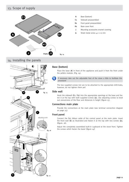
13. Scope of supply<br />
A<br />
C1<br />
J2<br />
H1<br />
J 8 pcs.<br />
14. Installing the panels<br />
G<br />
J1<br />
J1<br />
A<br />
C<br />
fig. 15<br />
adjusting screw<br />
J1<br />
fig. 16<br />
fig. 17<br />
G1<br />
fig. 14<br />
Base (bottom)<br />
A Base (bottom)<br />
C1 Sidewall preassembled<br />
G1 Front panel preassembled<br />
H1 Base cover front<br />
J Mounting accessories enamel covering<br />
J1 Sheet metal screw 4,2 x 10 mm<br />
Place the base (A) in front of the appliance and push it from the front under<br />
the pellets module. (Fig. 14).<br />
The two supplied screws (J2) are to be attached to the appropriate drill-holes,<br />
however, do not tighten them yet!<br />
Side wall<br />
If necessary take out the adjustable foot of the stove a little to facilitate this<br />
procedure!<br />
Hook the sidewall (C1 / C2) into the appropriate openings at the base and fasten<br />
it at the top with both supplied screws (J1). Use adjusting screws to level<br />
out unevenness of the floor and distances in height (figure 15).<br />
Connections main plate<br />
Provide the connections at the main plate (see terminal connection diagram<br />
on page 25).<br />
Front panel<br />
Connect the flat ribbon cable of the control panel at the main plate. Insert<br />
the front wall (G) as illustrated and fasten it at the top with two screws (J1),<br />
(figure. 16).<br />
Adjust the completely assembled built-in cupboard at the stove front. Tighten<br />
the screws which fasten the base! (figure 14)!<br />
page 11