
Create successful ePaper yourself
Turn your PDF publications into a flip-book with our unique Google optimized e-Paper software.
Edition July 2010<br />
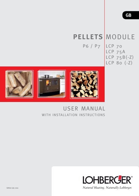
USER MANUAL<br />
WITH INSTALLATION INSTRUCTIONS<br />
GB<br />
PELLETS MODULE<br />
P6 / P7<br />
LCP 70<br />
LCP 75A<br />
LCP 75B(-Z)<br />
LCP 80 (-Z)<br />
page 1
1. Important notes prior to installation and first starting-up<br />
..........................................................................................4<br />
2. Technical data ...............................................................5<br />
3. Types of operation ........................................................6<br />
4. Functional description...................................................6<br />
Operation with pellets 6<br />
Operation with firewood 6<br />
5. Fuels .............................................................................7<br />
6. Chimney connection ......................................................7<br />
Suitable fuels 7<br />
Unsuitable fuels 7<br />
Impermissible fuels 7<br />
7. Air supply connection from outside (accesory) .............8<br />
8. Heating connection .......................................................9<br />
9. Electrical connection .....................................................9<br />
10. Requirements for the room where the appliance is situated<br />
...................................................................................9<br />
Floor - load capacity 9<br />
Room and ambient temperatures /humidity 9<br />
Output requirements for heating water 9<br />
Return flow increase 9<br />
11. Fire prevention ............................................................10<br />
12. Integration in built-in kitchen .....................................10<br />
Overhead installations 10<br />
Flue gas pipe 10<br />
Floor plate 10<br />
13. Scope of supply ...........................................................11<br />
14. Installing the panels ...................................................11<br />
15. Operation / Settings ...................................................12<br />
16. Menu – Top level .......................................................12<br />
Switching on the appliance 12<br />
Switching off the appliance 12<br />
Setting the heating output 12<br />
18. Main menu ..................................................................13<br />
17. Menu Settings ............................................................13<br />
Keylock 13<br />
Time/Date 13<br />
Automatic mode 14<br />
Heating period 14<br />
Keylock (function) 15<br />
Servicecode 15<br />
Reset 15<br />
page 2<br />
Important information in this <strong>manual</strong> is indicated by the following symbols:<br />
NOTE: Instructions for a proper use of the stove. It is the operator’s responsibility to follow these instructions<br />
CAUTION: This sign refers to particularly important notes.<br />
19. Menu Informations ......................................................16<br />
Summer/Winter 16<br />
Sensors 16<br />
Actuators 17<br />
System/SW Version 17<br />
Operating hours 17<br />
20. Operating the stove for the first time .........................18<br />
21. Heating operation with pellets ....................................18<br />
Switching the appliance on 18<br />
Setting the heating output 18<br />
22. Heating operation with firewood ................................19<br />
Ignition of firewood <strong>manual</strong>ly operated 19<br />
Ignition of firewood by means of pellet burner 19<br />
Adding of firewood during heating operation with pellets 19<br />
23. External Release / Remote control unit (provided by the<br />
customer) .........................................................................20<br />
24. Switching the appliance off ........................................20<br />
25. Display Maintenance / Cleaning .................................20<br />
Display Cleaning 20<br />
Display special cleaning 20<br />
Display maintenance 20<br />
26. Maintenance / Cleaning ..............................................21<br />
Vacuum-cleaning firebox 21<br />
28. Resetting safety temperature limiter ..........................22<br />
27. Error messages / Remedy of defects ..........................22<br />
29. Technical data .............................................................24<br />
30. Type test .....................................................................24<br />
Current supply 24<br />
Power input (start / operation) 24<br />
31. Terminal connection diagram ......................................25<br />
32. Operating panel language ..........................................25<br />
33. Menu diagram ............................................................26<br />
34. After-sales service /Ordering spare parts ..................27<br />
35. The LOHBERGER WARRANTY .......................................27<br />
SHORT INSTRUCTION ........................................................28<br />
DANGER: This sign indicates important codes of conduct so as to avoid injuries or damage to property.
When installing and starting-up the stove, observe the regulations<br />
and provisions of the building authorities and fire police applicable<br />
at the place of installation as well as the following standards /<br />
instructions:<br />
ÖNORM M7550<br />
Central heating boiler up to 100 °C: definition, requirements, tests,<br />
marking of conformity<br />
ÖNORM M7510/1<br />
Instructions for inspection of central heating systems<br />
ÖNORM M7510/2<br />
Instructions for inspection of central heating systems; standard<br />
values.<br />
ÖNORM B8130<br />
Safety devices<br />
ÖNORM B8131<br />
Closed water heating systems; safety requirements<br />
ÖNORM B8133<br />
Safety requirements water heating systems<br />
DIN 4751 Part 1<br />
Safety equipment for heating systems with supply temperatures up<br />
to 110 °C (120 °C in planning stage)<br />
DIN 4751 Part 2<br />
Safety equipment for heating systems with supply temperatures<br />
up to 110 °C (120 °C in planning stage); open and closed water<br />
heating systems up to 349 kW (300000 kcal/h) with thermostatic<br />
safety device<br />
With this solid fuel-fired stove you have selected a high-quality product made<br />
by LOHBERGER. Apart from the beautiful and timeless design we attach great<br />
importance to a fully developed combustion technique, high-quality materials<br />
as well as perfect workmanship. Correct handling and proper care are a prerequisite<br />
for high reliability and a long service life. Therefore please read the information<br />
in this <strong>user</strong> <strong>manual</strong> carefully. With the above in mind, we are convinced<br />
that this appliance will give satisfactory service for many years.<br />
Your LOHBERGER <strong>Heiz</strong> + Kochgeräte Technologie GmbH<br />
DIN 4751 Part 4<br />
Safety equipment for heating systems with supply temperatures up<br />
to 120 °C; closed water heating system with static heights exceeding<br />
15 m or rated heating output over 350kW.<br />
DIN 1988<br />
Drinking water supply systems on building sites<br />
(technical regulations).<br />
ÖNORM EN 303-5<br />
Boiler for solid fuels, charged <strong>manual</strong>ly or automatically up to 300<br />
kW. Definitions, requirements, tests and marking of conformity<br />
ÖNORM M7135<br />
Densified wood made of untreated wood or bark – wood pellets<br />
or briquettes<br />
ÖNORM M7136<br />
Densified wood made of untreated wood – wood pellets –<br />
quality assurance regarding transport and storage logistics<br />
ÖNORM M7137<br />
Densified wood made of untreated wood – wood pellets –<br />
Requirements regarding the owner’s pellets storage room<br />
TRVB H118<br />
Technical specifications regarding preventive fire protection for automatic<br />
heating systems with wood;<br />
page 3
1. Important notes prior to installation and first starting-up<br />
page 4<br />
Before connecting the stove to the chimney, you should inform the locally responsible<br />
chimney sweep.<br />
• Please read the information in this <strong>manual</strong> carefully before you install or<br />
start up your stove for the first time.<br />
• If the instructions are not followed, this results in the immediate expiration<br />
of our warranty obligations!<br />
• Keep these instructions in a safe place. Should they be lost, we will be<br />
happy to send you a new copy.You will find important information for your<br />
safety, for the use, care and maintenance of the appliance, so that you can<br />
enjoy your appliance for a long time. In case of queries please do not hesitate<br />
to contact the technical customer service of LOHBERGER.<br />
Caution! Possible risks of burns!<br />
The appliance becomes very hot when in use - be especially vigilant that small<br />
children are never in any danger!<br />
Proper Installation and starting-up<br />
Only if the stove has been installed by a trained technician, the safety of the<br />
appliance can be guaranteed.<br />
Therefore the complete electrical installation is to be carried out by a licensed<br />
company. Regulations such as VDE, ÖVE and other relevant standards are to be<br />
observed. Before starting-up the appliance the owner has to provide a system<br />
which is ready for operation (i.e. electrical wiring, a chimney which is available<br />
and suitable, appropriate solid fuel).<br />
Proper Operation<br />
Attention should be paid to the fact that the appliance is not at all childproof<br />
(doors, etc.) and therefore it must not be operated by children or other people<br />
who are not authorized or trained. If the appliance is not installed properly and<br />
if instructions (according to technical documentation, <strong>user</strong> <strong>manual</strong>) regarding<br />
the starting-up and operation of the appliance are not followed, all warranty<br />
claims will become null and void.<br />
Chimmney requirements for heating systems<br />
Prior to the first operation of the appliance the locally responsible chimney<br />
sweep has to prove the suitability and readiness for operation of the new or<br />
already existing chimney by a declaration of conformity. The owner has to ensure<br />
that the chimney is free from obstructions (no pluggings or coverings). Adequate<br />
ventilation (sufficient fresh air) is necessary in the boiler room. Please<br />
point out existing defects and /or alterations regarding the chimney and the<br />
heating system. Due to low exhaust gas temperatures during changes in season<br />
it is imperative that the chimney is tight and unsusceptible to moisture. Make<br />
sure that flue and exhaust gas can escape to the outside.<br />
Regular cleaning and maintenance of the appliance safety<br />
instructions<br />
Regular maintenance and care or cleaning of the stove, the heating gas draughts<br />
and the connection piece as well as the chimney are particularly important for<br />
the operational safety and efficiency of the stove. Please note the maintenance<br />
and cleaning instruction in this <strong>user</strong> <strong>manual</strong>. You can also request the help of<br />
your locally responsible chimney sweep to clean the fireplace. Only clean and<br />
properly adjusted appliances work efficiently. Please note the correct sequence<br />
of installation in this <strong>user</strong> <strong>manual</strong>.<br />
Safety instuctions<br />
When installing the stove, observe the regulations and provisions of the building<br />
authorities and fire police applicable at the place of installation. It is absolutely<br />
necessary to consult your locally responsible chimney sweep and the<br />
local building authority regarding questions of this nature.
2. Technical data<br />
1 Cover<br />
2 Control panel<br />
6 5<br />
3 Sidewall built-in cupboard<br />
4 Base panel lateral<br />
5 Base panel front<br />
6 Front panel built-in cupboard<br />
7 Main plate<br />
8 Ash pan<br />
22<br />
60 59,5<br />
21<br />
30<br />
1<br />
2<br />
3<br />
4<br />
9 Protective grating<br />
10 Pellet storage container<br />
11 Door contact shifter<br />
12 Drive shaft - rotary feeder<br />
13 Driving chain-conveying unit<br />
14 Auger motor<br />
15 Grate - Motor<br />
16 Flame temperature sensor<br />
16<br />
17<br />
18<br />
19<br />
20<br />
7<br />
8<br />
17 Auger<br />
18 Flame bruck<br />
19 Extraction shaft<br />
20 Burner brick<br />
21 Grate unit<br />
22 Exhaust fan<br />
4<br />
14<br />
9<br />
10<br />
11<br />
12<br />
13<br />
14<br />
15<br />
85<br />
page 5
3. Types of operation<br />
4. Functional description<br />
page 6<br />
The pellet stove can be operated either with wood pellets or billet wood.<br />
Operation with pellets<br />
The operation with pellets is predominantly suitable for heating the room<br />
where the appliance is installed. In this case the appliance is controlled by the<br />
use of preset control variables. Cooking operation and oven operation is only<br />
possible to a limited extent (the output can be increased by adding firewood).<br />
Appliances equipped with a central heating insert (optional equipment) can<br />
also generate hot water. The heat is transferred to the heating system (reservoir,<br />
heating circuit, etc.).<br />
Operation with firewood<br />
In addition to the operation with pellets, the appliance can also be conventionally<br />
heated with firewood. The basic functions of heating up and operating the<br />
oven are comparable to that of a normal wood burning stove. The operation<br />
with firewood is especially suitable for cooking and oven operation as well as<br />
for heating the room where the appliance is installed.<br />
It is also possible to automatically ignite the firewood by means of the pellet<br />
burner. Just load the combustion chamber with firewood and turn on the pellet<br />
burner.<br />
If firewood is added to the combustion chamber while the stove is running on<br />
pellets, the appliance recognises this and changes automatically to OPERATION<br />
WITH FIREWOOD.<br />
• Please note that with central heating appliances (type designation –Z) the<br />
controlled operation of the boiler is only possible when burning pellets.<br />
• When burning firewood, the appliance is also to be connected to the mains<br />
supply to avoid damages to parts of the appliance.<br />
• With pellet operation, the output for cooking and baking is only available<br />
to a limited extent; the output can be increased by adding firewood.<br />
The pellet stove can be operated either with wood pellets or billet wood.<br />
In addition to heating the room where the appliance is installed, the appliance<br />
can also be used for cooking and baking when it is running on firewood. With<br />
appliances featuring a central heating insert (type designation –Z, optional<br />
equipment) hot water is also generated. The heat is transferred to the heating<br />
system by this medium (reservoir, heating circuit, etc.). The cooking plate,<br />
stove body, viewing window, etc. give off radiant heat.<br />
For heating, switch the appliance on, it regulates either according to the pre-set<br />
heating output when operating on pellets or according to the set temperature<br />
of the boiler when operating appliances with central heating insert.<br />
The set temperature of the boiler can be influenced by the setting summer<br />
mode /winter mode. In addition, the output of the appliance can be affected<br />
by setting the power levels. Once the boiler has achieved the preset temperature,<br />
the selected power level limits the upward adjustment range of the pellet<br />
burner (for example this is necessary for cooking or baking). The switching on/<br />
off process of the appliance can be automated through an integrated automatic<br />
operation with a weekly operation schedule or by means of a remote control<br />
unit.<br />
Starting the appliance, irrespective of whether this is done <strong>manual</strong>ly or automatically,<br />
the tilting grate is cleaned automatically. The pellets are transported<br />
to the combustion chamber via the auger (with integrated rotary air lock as<br />
back-burn protection) and subsequently electrically ignited. The auger automatically<br />
supplies more pellets. The oxygen required for combustion flows in a<br />
controlled way to the combustion chamber.<br />
In the combustion chamber of the pellet module and in the subsequent firebox<br />
of the stove the gases produced during combustion burn off – heat is radiated<br />
via the exterior of the appliance as well as the heat exchanger surfaces. An extract<br />
fan, matching the amount of fuel and required combustion air, provides a<br />
stable negative pressure in the boiler and consequently ensures that flue gases<br />
escape through the chimney.
5. Fuels<br />
Wood storage<br />
Water<br />
content %<br />
6. Chimney connection<br />
fig. 1<br />
fig. 2<br />
Freshly cut from the forest 50 ~2,3<br />
Stored over winter 40 ~2,7<br />
Stored over summer 18-25 ~3,4<br />
Air dry 15-20 ~4,2<br />
Calorific value<br />
kWh/kg<br />
table 1<br />
Suitable fuels<br />
WOOD PELLETS<br />
It is imperative that only wood pellets conforming to the Austrian standards<br />
ÖNORM M7135 or DIN Plus are used. Diameter 6 mm, length max. 30 mm.<br />
Storage of wood pellets<br />
Pellets are supplied with a maximum water content of 10 %. Wood pellets must<br />
not be exposed to humidity during transport, make sure that they are stored in<br />
an absolutely dry place which is free of dirt.<br />
WOOD<br />
Billet wood (Fig. 2) should have a maximum water content of approximately<br />
30 % of the dried weight, be approximately 1/3 m long and be chopped small.<br />
In this way the billets are ignited rapidly, producing a better heat output than<br />
larger wood billets for the same amount of wood. Undercover in the open, fir,<br />
pine or alder wood should be stored a good 2 years, hard wood even 3 years.<br />
The significance of the water content of wood on the calorific value is shown<br />
in Table 1.<br />
Unsuitable fuels<br />
Moist wood, bark waste, sawdust, fine wood chips, brushwood, wood wool,<br />
wood chips. Use only very small amounts of paper for lighting.<br />
Burning such fuels generates high levels of pollutant emission, a lot of ash<br />
while the calorific value is very low.<br />
Impermissible fuels<br />
Surface-treated wood (veneered, painted, impregnated, etc.), chipboard wood,<br />
all types of waste (packaging waste), plastics, newspapers, rubber, leather,<br />
textiles, etc.<br />
Burning such materials will greatly pollute the environment and is prohibited<br />
by the legislator. It can also damage the stove and chimney. Furthermore the<br />
combustion of carbon energy is not allowed. The appliance has not been tested<br />
for operating on these fuels; therefore damages to the appliance cannot be<br />
ruled out and are not covered by warranty.<br />
For dimensions and detailed information on the chimney connection please refer<br />
to the operating <strong>manual</strong> of the stove.<br />
• In the event of a power failure, the chimney has to ensure the safe discharge<br />
of the flue gases from the appliance. Consequently it performs an important<br />
safety function and therefore several points are to be observed:<br />
• It is obligatory to provide a connection to a chimney that is non-susceptible<br />
to moisture and suitable for solid fuels.<br />
• The chimney has to conform to the specifications given on the type plate and<br />
in the <strong>user</strong> <strong>manual</strong> of the stove.<br />
• Prior to installation it is necessary to perform a calculation of the chimney as<br />
regards its dimensions.<br />
When installing dampers /draught regulators and explosion doors, please follow<br />
the installation instructions of the local chimney sweep<br />
• If the chimney draught is too high (>16 Pa) we recommend installing a damper<br />
(draught regulator)<br />
• Always connect the appliance to a separate chimney; no other heating appliances<br />
should be connected to the same flue or chimney system.<br />
• The flue pipe is to be connected to the chimney in compliance with the requirements<br />
of the Building Regulations. For further questions please consult<br />
your local chimney sweep.<br />
• Make sure that all flue pipes are leak-proof. Your local chimney sweep will<br />
be happy to give advice<br />
page 7
7. Requirements for the room where the appliance is situated<br />
Floor - load capacity<br />
B*<br />
page 8<br />
Prior to installing the appliance, make sure that the substructure<br />
of the floor is suitable to bear the weight of the appliance.<br />
Ensure that the stove is positioned horizontally and without<br />
vibration.<br />
8. Air supply connection from outside (accesory)<br />
Accessory:<br />
Air supply connection<br />
pellets module ø 50 mm<br />
A 20<br />
DN 100<br />
30<br />
DN 50<br />
85<br />
15*<br />
•… for an appliance height of 85<br />
cm<br />
fig. 3<br />
Accessory:<br />
Air supply connection stove ø 100<br />
mm (see <strong>user</strong> <strong>manual</strong> stove)<br />
Wall opening to<br />
be provided by<br />
the customer<br />
fig. 4<br />
Gerät<br />
Seitenabstand Bodenabstand<br />
A<br />
B<br />
LCP 70 (F1+B1+P) 21 33<br />
LCP 75 A (F1+B2+P) 21 33<br />
LCP 75 B (F2+B1+P) 23,5 33<br />
LCP 75 B-Z (F2+B1+P+Z) 23,5 19,5<br />
LCP 80 (F2+B2+P) 23,5 33<br />
LCP 80-Z (F2+B2+P+Z) 23,5 19,5<br />
table 2<br />
Room and ambient temperatures /humidity<br />
The appliance is suitable for rooms with normal humidity and<br />
room temperatures ranging from +5 °C to +20 °C. Should room<br />
temperatures fall below 5 °C, it is imperative to add appropriate<br />
antifreeze to the water.<br />
The appliance is not splash proof; therefore it must not be<br />
installed in wet rooms such as bathroom units.<br />
Basically, the appliance is dependent on indoor air, that means the air supply<br />
needed for combustion is extracted from the room where the appliance is<br />
positioned. Subsequently air supply is to be provided from outside by means<br />
of a ventilation opening. To do this, an opening of 10-15 cm in diameter has to<br />
be provided at one exterior wall of the room where the appliance is located.<br />
Outside a stable protective grating is to be fitted. Furthermore, at places where<br />
strong winds are prevalent or places which are exposed to weather, a protection<br />
against wind and rain is required.<br />
If it is not possible to provide an opening to the outside from the room where<br />
the appliance is positioned, it is also possible to create an opening in an adjoining<br />
room. Make sure that the adjoining room has a permanent connection<br />
to the room where the pellet stove is positioned by means of a ventilation<br />
grate.<br />
If there are additional heating units in the same room, the ventilation openings<br />
must provide adequate air supply for combustion to ensure proper operation<br />
of all appliances!<br />
Too low pressures in the room where the appliance is located (e.g. caused by<br />
ventilation systems, extractor hoods etc.) or in the pellets container (e.g. caused<br />
by pneumatic appliances) are likely to impair the functioning of the fire place and<br />
their safety (technique) and are therefore not permitted.<br />
Air supply connection from outside (optional equipment)<br />
To ensure a sufficient supply of combustion air in the case of tightly sealed<br />
windows and low-energy houses equipped with ventilation systems or when<br />
ducted extractor hoods are used, it may be necessary to provide fresh combustion<br />
air from outside.<br />
Even with an outdoor air connection the requirements for an operation that is<br />
independent from the ambient air are not fulfilled!<br />
The dimensions for fitting are shown in „Figure 4“ as well as „Table 2“. Please<br />
note the changes to the dimensions due to the adjustment of the height of the<br />
appliance or of the stove frame.<br />
• It is not allowed to install shut-off devices (flaps, dampers, …) in the air<br />
supply line!<br />
• The air supply line consisting of non-combustible materials must be a maximum<br />
of 4 m in length and must not have too many bends!<br />
• To avoid condensation, the air supply line must be insulated!<br />
• The air flue must be at least 50 or 100 mm, respectively, in diameter. If<br />
rectangular tubes are used, they must maintain the appropriate diameter!<br />
• If the air supply line runs directly to the outside, it has to be protected<br />
against wind!<br />
• The supply of external combustion air from above may only be provided by<br />
means of chimney systems which have been approved by us..<br />
For the technical acceptance of the heating system, the chimney sweep is required<br />
to check the entire installation, in particular for sufficient combustion air supply.
9. Heating connection<br />
Flue pipe connection left side:<br />
Flue pipe connection right side:<br />
29<br />
47,5*<br />
Heating flow 1“<br />
inlet /outlet temperature<br />
safety relief valve 1/2“<br />
4,8<br />
Heating return<br />
flow 1“<br />
65*<br />
10. Electrical connection<br />
power line<br />
53,5<br />
61<br />
* for an appliance height of 85 cm!<br />
EMERGENCY OFF<br />
connecting socket<br />
* … for an appliance height of 85 cm<br />
53,5<br />
46<br />
* for an appliance height of 85 cm!<br />
4,8<br />
65*<br />
Heating flow 1“<br />
Heating return<br />
flow 1“<br />
smoke/fire alarm<br />
inlet /outlet temperature<br />
safety relief valve 1/2“<br />
*<br />
29<br />
47,5*<br />
fig. 5<br />
StOvE PEllEtS MOdulE<br />
fig. 7<br />
fig. 6<br />
Output requirements for heating water<br />
Heat requirement during operation must exceed 1,6 kW. If the heat output falls<br />
below this value, the built-in safety devices will be activated and /or the appliance<br />
will be shut down.<br />
Return flow increase<br />
The return flow temperature must be at least 55 °C at the return flow connecting<br />
piece of the appliance (in the ideal case 60 °C), otherwise this will result in<br />
the building-up of soot and tar and as a consequence in corrosion.<br />
For dimensions and detailed information on the heating connection please refer to<br />
the installation and operation instructions of your stove.<br />
• When connecting the appliance by means of a plug to a socket, pay attention<br />
to the appropriate polarity (if necessary use a mains plug with<br />
an anti-twist protection) because the appliance must be connected in the<br />
proper phase!<br />
• An emergency power-off switch or an individual safety device is to be installed<br />
into the main distribution (for maintenance works, etc.<br />
• It is imperative that electrical connections regarding the appliance are to<br />
be carried out by a qualified professional in accordance with the applicable<br />
technical regulations, especially the VDE- and OVE-regulations. We do not<br />
accept liability for damages to the appliance as a result of inexpert connections<br />
and are subsequently excluded from warranty.<br />
• All electrical connecting cables leading from and to the appliance must not<br />
touch hot exterior surfaces of the appliance or of the chimney flue. The<br />
cables must not be laid over sharp edges.<br />
• The appliance has been exclusively designed to operate with an AC voltage<br />
of 230 V /50 Hz.<br />
• Voltage fluctuations ranging from –15 % up to +10 % are permissible.<br />
If possible the mains cable which is supplied with the appliance should be connected<br />
to the power line prior to the installation of the appliance!<br />
• The connection is carried out by means of a 3-pole mains cable (to be supplied<br />
with the appliance).<br />
• Do not use sockets with power plugs without anti-twist safeguard as the appliance<br />
is dependent on the phase!<br />
• It is imperative that you install a protective earth conductor!<br />
• A 5 x 20 2,5 A T glass tube safety fuse serves as main fuse. The fuse is installed<br />
at the front wall of the built-in cupboard (inside).<br />
• An emergency stop switch is to be installed by the owner (for maintenance<br />
works, etc.).<br />
We strongly recommend the installation of a smoke detector or fire warning device<br />
which interrupts the current supply of the appliance in case of an emergency! Objects<br />
which have been left inadvertently on the cooking surface are likely to catch fire<br />
in case of automatic starting-up of the pellet burner (e.g. with an automatic timing<br />
device).<br />
page 9
11. Fire prevention<br />
page 10<br />
≥ 20<br />
≥ 60<br />
≥ 20<br />
≥ 20<br />
Fire protection unit<br />
≥ 75<br />
12. Integration in built-in kitchen<br />
*... included in the scope of supply for the PELLETS MODULE!<br />
A + B + C + D<br />
ca. 64<br />
*<br />
fig. 8<br />
fig. 9<br />
fig. 10<br />
fig. 11<br />
fig. 12<br />
fig. 13<br />
Keep adequate distance from combustible items (wood panelling, furniture,<br />
curtains, etc.) around the stove. The walls in the area of the stove must be<br />
rendered fireproof extending up the full height of the walls and covering a<br />
width of at least 50 cm to either side or to the front beyond the fireplace.<br />
(Fig. 7).<br />
The safety distance with items to be protected (e.g. combustible walls, walls<br />
with combustible components, suspended kitchen cupboards and carrying<br />
walls made of reinforced concrete) is at least 20 cm (Fig. 8).<br />
Between the stove and the pellets module a fire protection sidewall has<br />
already been provided. (Fig. 8).<br />
When attached to combustible materials or installed in a built-in kitchen<br />
or attachment to an electric stove or any other appliance, a fire protection<br />
The <strong>Lohberger</strong> fire protection units VBS have only been tested in connection with<br />
the <strong>Lohberger</strong> – stove series VARIOLINE (appliance type LM.., LC.., LCP.., …)!<br />
sidewall VBS (+5 cm or +7,5 cm, resp.) must be provided. (Fig. 9).<br />
The maximum hight of the fixtures is up to the appliance height (standard<br />
height 85 cm). Fixtures which are higher (f. e. tall cupboard) have to be at<br />
least 20 cm from the pellets module away. (figure 9).<br />
Overhead installations<br />
In the area of the pellets module the swivel range of the cover for adding fuel<br />
must be taken into account! (Fig. 10)<br />
Maintain a minimum distance of 75 cm and ensure adequate rear ventilation<br />
for the suspension boxes to avoid heat being trapped. (Fig. 10).<br />
Flue gas pipe<br />
When installing the flue gas pipe, adhere to the following minimum distances<br />
to combustible building materials: wall distance 20 cm, ceiling distance<br />
40 cm.<br />
Floor plate<br />
With a combustible floor (wood, plastic, wall to wall carpet,...) a floor plate<br />
made of steel, copper or another noncombustible material must be used.<br />
This surface must protrude the stove outline by at least 5 cm, on the operating<br />
side by at least 30 cm.<br />
With this type of questions it is imperative to consult your responsible<br />
chimney sweeper.<br />
The clearance for the integration in a built-in kitchen is to be calculated as<br />
follows:<br />
Distance fire protection A 5-15 cm<br />
+ Basic width of appliance B 70-80 cm<br />
+ Extra clearance for inspection C * 7,5 cm<br />
+ Width of pellets module D 30 cm<br />
= Installation dimension<br />
Examples of installations:<br />
Exampel with LC 80<br />
A + B + C + D<br />
7,5 + 80 + 7,5 + 30<br />
= 125 cm installation dimension
13. Scope of supply<br />
A<br />
C1<br />
J2<br />
H1<br />
J 8 pcs.<br />
14. Installing the panels<br />
G<br />
J1<br />
J1<br />
A<br />
C<br />
fig. 15<br />
adjusting screw<br />
J1<br />
fig. 16<br />
fig. 17<br />
G1<br />
fig. 14<br />
Base (bottom)<br />
A Base (bottom)<br />
C1 Sidewall preassembled<br />
G1 Front panel preassembled<br />
H1 Base cover front<br />
J Mounting accessories enamel covering<br />
J1 Sheet metal screw 4,2 x 10 mm<br />
Place the base (A) in front of the appliance and push it from the front under<br />
the pellets module. (Fig. 14).<br />
The two supplied screws (J2) are to be attached to the appropriate drill-holes,<br />
however, do not tighten them yet!<br />
Side wall<br />
If necessary take out the adjustable foot of the stove a little to facilitate this<br />
procedure!<br />
Hook the sidewall (C1 / C2) into the appropriate openings at the base and fasten<br />
it at the top with both supplied screws (J1). Use adjusting screws to level<br />
out unevenness of the floor and distances in height (figure 15).<br />
Connections main plate<br />
Provide the connections at the main plate (see terminal connection diagram<br />
on page 25).<br />
Front panel<br />
Connect the flat ribbon cable of the control panel at the main plate. Insert<br />
the front wall (G) as illustrated and fasten it at the top with two screws (J1),<br />
(figure. 16).<br />
Adjust the completely assembled built-in cupboard at the stove front. Tighten<br />
the screws which fasten the base! (figure 14)!<br />
page 11
15. Operation / Settings<br />
Display (illuminated)<br />
Display options top level:<br />
• Appliance status<br />
• Clock time<br />
• Operating status<br />
• Power level<br />
• Button”LEFT“<br />
• To reduce the output in the top<br />
level.<br />
• To switch from one adjustment<br />
point to the previous in the adjustment<br />
levels<br />
• To return by one menu level<br />
each.<br />
16. Menu – Top level<br />
page 12<br />
• BUTTON “UP“<br />
• To select the desired menu item in all sub-levels<br />
• To activate the key lock (only with activated key<br />
lock function) by simultaneous pressing of the<br />
buttons UP and DOWN in the top level<br />
• To switch on the functions in the adjustment levels<br />
• To increase values in the adjustment levels<br />
Stove off 13:45<br />
Burner off<br />
• Button „DOWN“<br />
• To select the desired menu item in all sub-levels<br />
• To activate the key lock (only with activated key<br />
lock function) by simultaneous pressing of the<br />
buttons UP and DOWN in the top level.<br />
• To switch on the functions in the adjustment levels.<br />
• To reduce the values in the adjustment levels<br />
OK<br />
Button „OK“<br />
• To enter all sub-levels of the menu, starting<br />
from the top level.<br />
• To confirm the selected sub-levels of the<br />
menu.<br />
• To confirm the set values and to switch from<br />
one adjustment point to the next in the adjustment<br />
levels<br />
• To confirm error messages by pressing and<br />
holding the button (approx. 2 seconds)<br />
Button “ON / OFF“<br />
To switch the appliance on and off in the top level.<br />
Button „RIGHT“<br />
• To increase output in the top level.<br />
• To switch from one adjustment point to the<br />
next in all adjustment levels.<br />
Stove ON 13:45<br />
In the top level of the menu (figure 18) the current appliance status is shown.<br />
Furthermore basic operating functions such as switching the appliance on/off,<br />
Burner OFF<br />
setting the heating output as well as activating the key lock are possible.<br />
O u t p u t < | | | | | | - - - - > DISPLAY OPTIONS<br />
fig. 19<br />
fig. 18<br />
Line 1 – Display of the current appliance status as well as of the current clock<br />
time<br />
Line 2 – Display of the respective operating status general notes and error<br />
messages.<br />
Line 3 – Display of the selected output level<br />
LIGHTING<br />
To switch on the display lighting press an operating button, after approx. 30<br />
seconds the lighting is turned off again automatically.<br />
Switching on the appliance<br />
Press once in the top level of the menu. The display “StOve ON” appears<br />
as well as the operating status BurNer activatiON. The appliance<br />
turns on.<br />
Switching off the appliance<br />
Press once in the top level of the menu. The display “StOve OFF” appears<br />
as well as the operating status BurNer OFF. The appliance shuts down.<br />
Setting the heating output<br />
To lower the heating output, press in the top level of the menu.<br />
To raise the heating output, press in the top level of the menu.<br />
Adjustment range heating output:<br />
3 – 10 for air heaters (P6)<br />
5 – 10 for central heating appliances (P7, type-designation –Z)
18. Main menu<br />
-- Main menu --<br />
>Settings <<br />
information<br />
Factory level<br />
17. Menu Settings<br />
-- Main menu --<br />
>Settings <<br />
information<br />
Default setting<br />
-- Settings --<br />
>time/Date < |<br />
automatic mode |<br />
Heating period |%<br />
-- Settings --<br />
>time/Date < |<br />
automatic mode |<br />
Heating period |%<br />
-- time/Date --<br />
>clock time 13:46 <<br />
Date 04/09/2009<br />
-- time/date --<br />
time 13:46<br />
>Date 04/09/2009 <<br />
fig. 20<br />
fig. 21<br />
fig. 22<br />
fig. 23<br />
fig. 24<br />
fig. 25<br />
Key lock<br />
The key lock prevents an accidental adjustment of the appliance settings (e.g.<br />
when cleaning the control panel, caused by children, …) and can be switched on<br />
or off if required<br />
To switch on the key lock, press the buttons and at the same time.<br />
To switch off the key lock, press the buttons and at the same time.<br />
The key lock function is switched off when the appliance is delivered and can be<br />
activated in the menu Settings --> See point Key lock (function)<br />
If the key lock is activated, it is still active after a possible power failure.<br />
To enter the main menu from the top level of the menu, press the >OK< button<br />
once.<br />
Settings To perform appliance settings<br />
information Display /Information on the appliance and its components<br />
Default setting Detailed settings (service technician)<br />
To get to the menu Settings from the main menu, select the menu SETTINGS<br />
with or and press the >OK< button once.<br />
Time /Date: To set clock time and date<br />
Automatic mode: To change between <strong>manual</strong> operation and operation with adjustable<br />
heating times.<br />
Heating period: Adjustment level for heating times<br />
Key lock: To switch the key lock on/off<br />
Servicecode: To reset the cleaning /maintenance interval by the service technician<br />
Reset: To reset all settings made by the customer.<br />
For central heating appliances.<br />
For central heating appliances:<br />
Summer/Winter: To change from summer to winter mode<br />
Time/Date<br />
Select the menu Time/Date in the menu Settings with or and press the<br />
OK button once (figure 22). Select sub-menu clock time by pressing the buttons<br />
or (figure 23).<br />
Press OK button once, the display Hour flashes<br />
Adjust accordingly by pressing the buttons or<br />
Press OK button once, the set value is stored, the display Minute flashest<br />
Adjust accordingly by pressing the buttons or .<br />
Press OK button once, the set value is stored, the display day flashes<br />
Adjust by pressing the buttons or<br />
Press OK button once, the set value is stored<br />
Select sub-menu date by pressing the buttons<br />
Press OK button once, the display Day flashes<br />
or (figure 24)<br />
page 13
page 14<br />
-- Settings -time/date<br />
|<br />
>automatic mode < |<br />
Heating period |%<br />
-- automatic mode --<br />
>auto OFF <<br />
-- automatic mode --<br />
>auto ON <<br />
-- Settings -time/Date<br />
|<br />
automatic mode |<br />
>Heating period < |%<br />
-- Heating period --<br />
>MO< We Fr Su<br />
tu tH Sa aLL<br />
--Heating period MO--<br />
>t1 10:30 - 13:00 <<br />
t2 13:30 - 17:00<br />
fig. 26<br />
fig. 27<br />
fig. 28<br />
fig. 29<br />
fig. 30<br />
fig. 31<br />
Adjust by pressing the buttons or<br />
Press OK button once, the set value is stored and the display Year flashes<br />
Press OK button once, the set value is stored<br />
Press 3 times to return to the top level of the menu.<br />
Automatic mode<br />
The automatic operation determines whether the appliance is operated <strong>manual</strong>ly<br />
(standard setting OFF) or whether the internal clock is used for switching the appliance<br />
on /off.<br />
Select the menu Automatic operation in the menu SETTINGS by pressing<br />
or (Fig. 25)<br />
Press OK button once.<br />
The setting can be changed by pressing the buttons or geändert<br />
werden (Fig. 26/27).<br />
Press the button 3 times to return to the top level of the menu.<br />
Should the appliance be switched on or off by means of an external command, for<br />
example by means of a room thermostat, a buffer thermostat etc., the AUTOMATIC<br />
MODE can be changed to OFF or ON.<br />
However, when switching AUTOMATIC MODE to ON, an external command will only<br />
be taken into account within the pre-set heating times!<br />
Heating times<br />
Here you can select two heating times each for each individual weekday<br />
(MO, TU, WE …). If the same heating times shall apply for the whole week, two<br />
heating times each can be selected with ALL.<br />
CAUTION: The setting ALL will overwrite all settings of the individual weekdays!<br />
Select the menu Heating period in the menu Settings by pressing the buttons<br />
or and press the OK once (figure 28).<br />
Select weekday by pressing the buttons<br />
(figure 29).<br />
or and press OK once<br />
Select heating time (T1 /T2) by pressing the buttons or (figure 30)<br />
Press OK button once, the display Turn-on time/hour flashes.<br />
Adjust value by pressing the buttons or .<br />
Press the OK button once, the set value is stored, the display Turn-on<br />
time/minute flashes<br />
Adjust value by pressing the buttons or .<br />
Press OK button once, the set value is stored, the display Turn-off<br />
time/hour flashes.<br />
--> For settings see turn-on time.<br />
Press four times to return to the top level of the menu.
-- Settings -automatic<br />
mode |<br />
Heating period |<br />
>Keylock < |%<br />
-- Keylock --<br />
>Keylock OFF <<br />
-- Keylock --<br />
>Keylock ON <<br />
-- Settings --<br />
Heating period |<br />
Keylock |<br />
>Servicecode < |%<br />
-- Servicecode --<br />
>Servicecode **** <<br />
-- Servicecode --<br />
code wrong<br />
-- Settings --<br />
Keylock |<br />
Service code |<br />
>reset < |%<br />
-- reset --<br />
reset with OK<br />
fig. 32<br />
fig. 33<br />
fig. 34<br />
fig. 35<br />
fig. 36<br />
fig. 37<br />
fig. 38<br />
fig. 39<br />
Key lock (function)<br />
To use the key lock in the top level of the menu, the key lock function must be<br />
activated. If the keylock function is switched on, the key lock will be automatically<br />
activated after a power failure.<br />
Select the menu Keylock in the menu Settings by pressing the buttons or<br />
and press OK button once (figure 31).<br />
The key lock function can be activated /deactivated by pressing the buttons<br />
or (figure 32/33).<br />
Press button 3 times to return to the top level of the menu.<br />
Now the key lock can be activated or deactivated in the top level of the menu<br />
by simultaneous pressing of the buttons and .<br />
Service code<br />
Reset<br />
To confirm cleaning works or maintenance works that have been performed on the<br />
appliance, a service code is to be entered. As a consequence the relevant internal<br />
service hour meter will be reset.<br />
• Cleaning works are necessary after 250 operating hours and this will be<br />
indicated in the top level of the menu by the display “APPLIANCE CLEAN-<br />
ING”, confirmation with cleaning code 1234<br />
• Maintenance works are necessary after 2000 operating hours and this will<br />
be shown in the top level of the menu by “APPLIANCE MAINTENANCE”, a<br />
confirmation by a service technician is required.<br />
Select the menu Servicecode in the menu Settings by pressing the buttons<br />
or and press OK button once (figure 34).<br />
Press OK button once, the first digit flashes.<br />
Adjust number by pressing the buttons or (figure 35).<br />
Press OK button once, the next digit flashes.<br />
After entering the last digit, press the OK button once, when the correct<br />
service code has been entered, the message “cLeaNiNg cONF.” or “MaiNteNaNce<br />
cONF.” appears in the text box.<br />
Press the OK button once, the service hour meter for the maintenance<br />
interval will be reset (resetting not visible!).<br />
If an incorrect service code is entered, the message cODe WrONg appears in<br />
the text box (figure 36).<br />
Press OK button once, repeat the steps for the entry of the service code<br />
and enter the correct service code.<br />
Press button twice to return to the top level of the menu<br />
In case of a reset all customer specific settings such as heating times etc. will be<br />
reset to default setting!<br />
Select the menu RESET in the menu SETTINGS by pressing the buttons or<br />
and press OK button once (figure 37).<br />
Press OK button once, a reset will be carried out (figure 38).<br />
The display returns to the menu Settings.<br />
Press the button twice to return to the top level of the menu.<br />
page 15
page 16<br />
-- Settings --<br />
Service code |%<br />
reset |<br />
>Summer/Winter < |<br />
-- Summer/Winter --<br />
>Winter mode <<br />
-- Summer/Winter --<br />
>Summer mode <<br />
19. Menu Informations<br />
-- Main menue --<br />
Settings<br />
>informations <<br />
Default setting<br />
-- informations --<br />
>Sensors < |<br />
actuators |<br />
System/SWversion |%<br />
-- informations --<br />
>Sensors < |<br />
actuators |<br />
System/SWversion |%<br />
-- Sensors --<br />
>Door cntact ON< |<br />
grate contact ON |<br />
release ON |%<br />
-- Sensoren -t<br />
Flame 38 |%<br />
t Flue gas 26 |<br />
>t Plug-in 24< |%<br />
-- Sensors -t<br />
Flue gas 26 |%<br />
t Plug-in 24 |<br />
>t Boiler 29< |<br />
fig. 40<br />
fig. 41<br />
fig. 42<br />
fig. 43<br />
fig. 44<br />
fig. 45<br />
fig. 46<br />
fig. 47<br />
fig. 48<br />
Summer/Winter (only for appliances with central heating insert)<br />
To reduce heat output in summer, the appliance can be changed from winter to<br />
summer mode. This setting limits the upwards adjustment range of the pellet<br />
burner.<br />
• Boiler set-point temperature WINTER 75°C<br />
• Boiler set-point temperature SUMMER 65°C<br />
Select the menu SUMMER/WINTER by pressing or and press the<br />
OK button once (figure 38).<br />
The setting can be changed by pressing the buttons or (figure 40/41).<br />
Press button three times to return to the top level of the menu.<br />
To enter the menu Information from the main menu, select the menu Information<br />
by pressing the button or and press the OK once (figure 42).<br />
Sensors Passive appliance components such as sensors, …<br />
Actuators Active appliance components such as motors, blowers, …<br />
Appliance / SW Display of the pre-set appliance type and of the installed<br />
Version<br />
software version.<br />
Operating hours Display of the total amount of operating hours as well as<br />
how many operating hours are left until the next maintenance<br />
of the appliance is due.<br />
Sensors<br />
Select the menu Sensors in the menu Information by pressing the button<br />
or and press the OK once (figure 44)<br />
Paging through the menu items is possible by pressing the button or<br />
(figure 45-47).<br />
ON /OFF (OFF = door open)<br />
ON /OFF (OFF = grate open)<br />
ON /OFF (OFF = no external command)<br />
Current flame temperature<br />
Current exhaust gas temperature<br />
Current discharge chute temperature<br />
Current boiler temperature – (only for appliances with central heating insert)<br />
Press three times to return to the top level of the menu.
-- informations --<br />
Sensors |<br />
>actuators < |<br />
System/SWversion |%<br />
-- actuators --<br />
>Plug-in OFF < |<br />
clocking 0 |<br />
Fan OFF |%<br />
-- actuators --<br />
Speed 0 |<br />
grate motor OFF |<br />
>ignition OFF< |%<br />
-- actuators -grate<br />
motor OFF |<br />
ignition OFF |<br />
>Pump OFF< |%<br />
-- informations --<br />
Sensors |<br />
actuators |<br />
System/SWversion |%<br />
-- System/SWversion --<br />
P7/LcP75B/LcP80N<br />
SWversiona 8.27<br />
SWversionD 1. 6<br />
-- informations -actuators<br />
|<br />
System/SWversion |<br />
>Operating hours < |%<br />
-- Operating hours --<br />
total 0<br />
until maint. 2000<br />
fig. 49<br />
fig. 50<br />
fig. 51<br />
fig. 52<br />
fig. 53<br />
fig. 54<br />
fig. 55<br />
fig. 56<br />
Actuators<br />
Select the menu Actuators in the menu Information by pressing the button<br />
or and press the OK once (figure 48).<br />
Paging through the menu items is possible by means of pressing the button<br />
or (figure 49-51).<br />
ON /OFF (OFF = Auger off)<br />
Current value<br />
ON /OFF (OFF = Blower off)<br />
Current value<br />
ON /OFF (OFF = Motor off)<br />
ON /OFF (OFF = Ignition off)<br />
ON /OFF (OFF = Pump off) – (only for appliances with central heating insert)<br />
Press button three times to return to the top level of the menu.<br />
System/SW Version<br />
Select the menu System /SW Version in the menu Information by pressing the<br />
button or and press the OK once (figure 52).<br />
System type<br />
Software version main circuit board<br />
Software version control panel<br />
Press three times to return to the top level of the menu.<br />
Operating hours<br />
Select the menu Operating hours in the menu Information by pressing the button<br />
or and press the OK once (figure 54).<br />
Display of the Operating hours<br />
Display Operating hours until next maintenance of the appliance<br />
Press three times to return to the top level of the menu.<br />
page 17
20. Operating the stove for the first time<br />
21. Heating operation with pellets<br />
page 18<br />
Stove ON 13:45<br />
Burner start-up<br />
O u t p u t < | | | | | | - - - - ><br />
Stove ON 13:45<br />
fig. 57<br />
Burner ON<br />
O u t p u t < | | | | | | - - - - ><br />
fig. 58<br />
• Do not leave small children unattended in the vicinity of the stove: the<br />
heating system is not childproof!<br />
• Prior to the first start-up all connections (chimney flue connection, power<br />
supply, etc.) are to be checked.<br />
• The viewing glass as well as the door become very hot when the stove is in<br />
use (temperatures up to 300 °C). Pay attention to the fact that these parts<br />
must not be touched when the stove is in operation.<br />
• Keep the firebox door closed at all times, even if the stove is not in use.<br />
• Make sure that no objects are in the combustion chamber, in the firebox as<br />
well as in the oven.<br />
• Only after the installation is completed in accordance with the <strong>user</strong> <strong>manual</strong><br />
and installation instructions, is it allowed to charge the storage container<br />
with pellets (at least 5 kg).<br />
General note – Surfaces<br />
Only high-quality air-drying varnish is used which does not smell nor give off<br />
fumes when heated up for the first time if it is allowed to dry completely (at<br />
room temperature). If the appliance is heated up shortly before the varnish has<br />
hardened, an unpleasant smell and fume will be temporarily produced. Please<br />
give the room where the appliance is located a good airing.<br />
Charging the storage container<br />
Make sure that you use approved pellets which conform to ÖNORM M7135/DIN<br />
51731 – see imprint on the pellets bags or consult your pellets supplier. Open<br />
the container lid. To avoid raising of dust, pour pellets slowly and not from too<br />
high a position. After feeding the pellets, the lid is to be closed and should<br />
remain closed during operation.<br />
• While the appliance operates on pellets, the damper (start-up flap) (see<br />
instruction <strong>manual</strong> stove) must not be opened!<br />
• Set both stove air regulators to level “0”!<br />
The regulation is determined by the specified boiler set-point temperature<br />
(75°C or 65°C respectively, see setting SUMMER /WINTER).<br />
Should the boiler set-point temperature be exceeded by 10°C, the appliance<br />
shuts down automatically display burner OFF and switches on again once the<br />
boiler set-point temperature has fallen below the value by 3 °C.<br />
The appliance might resume operation automatically at any time, therefore please<br />
note the information in point External Release /Remote control unit!<br />
Switching the appliance on<br />
Press the button once in the top level of the menu.<br />
The display StOve ON appears as well as the operating status burner start-up<br />
(figure 56).<br />
The appliance switches on.<br />
Setting the heating output<br />
Setting of the heating output in the top level of the menu (figure 57).<br />
Reduce heating output by pressing the button .<br />
Increase heating output by pressing the button .<br />
Adjustment range heating output:<br />
3 - 10 for air heaters (P6)<br />
5 - 10 for central heating appliances (P7, type designation -Z)<br />
If the heating output is not sufficient although it has been set at the highest<br />
level, the temperature can be increased by loading firewood.
22. Heating operation with firewood<br />
Stove OFF 13:45<br />
Burner OFF<br />
O u t p u t < | | | | | | - - - - ><br />
Stove OFF 13:45<br />
Burner activation<br />
O u t p u t < | | | | | | - - - - ><br />
Stove OFF 13:45<br />
Firewood operation<br />
O u t p u t < | | | | | | - - - - ><br />
Stove OFF 13:45<br />
fig. 59<br />
fig. 60<br />
fig. 61<br />
Firewood operation<br />
O u t p u t < | | | | | | - - - - ><br />
fig. 62<br />
Ignition of firewood <strong>manual</strong>ly operated<br />
• Set the regulator for primary air (bottom) to level 3 and set the regulator<br />
for secondary air to level 6.<br />
• Open heating door, load 2 to 3 small pieces of firewood or wood-shavings<br />
onto the grate.<br />
• Place 2 to 3 small logs on top of them and light them.<br />
• Close heating door, leave the ash door just a crack open and allow the fire<br />
to burn brightly<br />
• Pull damper (start-up flap) handle (see instruction <strong>manual</strong> stove).<br />
Close ash door and damper (start-up flap) after the preheating phase is complete.<br />
The display still shows StOve OFF or BurNer OFF (figure 58).<br />
Ignition of firewood by means of pellet burner<br />
• Do not open the damper (start-up flap)!<br />
• If the firewood continues to burn for an extended period, set the regulators<br />
for primary air (bottom) and secondary air (top) according to the enclosed<br />
operating instructions of the stove.<br />
• Open heating door, place 2 or three small pieces of firewood (beech wood)<br />
onto the grate (1.6 kg to 2 kg according to the operating instructions of<br />
the stove)<br />
• Close heating door.<br />
Press the button once in the top level of the menu.<br />
The display StOve ON as well as the operating status BurNer activatiON<br />
appears (figure 59).<br />
Because of the increased output caused by the burning of firewood, the pellet<br />
burner switches to operation with firewood, the display shows the operating<br />
status FireWOOD OPeratiON (figure 60).<br />
Should no further increase in the output be identified while the stove is operating<br />
on firewood, the appliance automatically returns to Operation with pellets<br />
if the appliance is switched ON.<br />
If the stove continues to burn firewood, the pellet burner shuts down automatically.<br />
If no more firewood is added, the appliance changes after a safety<br />
period automatically to heating operation with pellets according to the pre-set<br />
heating output.<br />
Adding of firewood during heating operation with pellets<br />
If the stove is loaded with more firewood while the appliance is being heated<br />
with pellets, the appliance first switches to operation with firewood.<br />
The display StOve ON as well as the operating status FireWOOD OPeratiON<br />
appears (figure 61).<br />
In the event that the appliance is operated with a low heating output, it may occur<br />
that the operation with firewood will not be immediately identified, thus the<br />
ignition!<br />
If the stove continues to burn firewood, the pellet burner shuts down automatically.<br />
If no more firewood is added, the appliance changes after a safety period<br />
automatically to heating operation with pellets with the pre-set heating output.<br />
If the firewood continues to burn for an extended period, set the regulator for<br />
primary air (bottom) to level 3 and the regulator for secondary air (top) to level 6.<br />
CAUTION: During operation with firewood, there is no automatic adjustment of the<br />
output through the pellet stove control. The adjustment of the output depends on<br />
the amount of fuel added. With appliances featuring a central heating insert, only<br />
the heating circuit pump (provided by the customer) is switched on or off.<br />
page 19
23. External Release / Remote control unit (provided by the customer)<br />
page 20<br />
Care should be taken as the appliance might<br />
switch on automatically at any time!<br />
Objects that have been inadvertently placed on the<br />
cooking surface could ignite if the pellet burner<br />
starts up automatically (e.g. start-up according to a<br />
pre-programmed time, …) and start a fire.<br />
Therefore we recommend installing a smoke or fire<br />
detector that makes a warning sound in case of<br />
emergency and interrupts the power supply of the<br />
appliance!<br />
24. Switching the appliance off<br />
Stove OFF 13:45<br />
Burner OFF<br />
O u t p u t < | | | | | | - - - - ><br />
Stove ON 13:45<br />
aPPLaiNce cLeaNiNg<br />
O u t p u t < | | | | | | - - - - ><br />
Stove ON 13:45<br />
SPeciaL cLeaNiNg<br />
O u t p u t < | | | | | | - - - - ><br />
Stove ON 13:45<br />
fig. 63<br />
25. Display Maintenance / Cleaning<br />
fig. 64<br />
fig. 65<br />
aPPLiaNce MaiNteNaNce<br />
O u t p u t < | | | | | | - - - - ><br />
fig. 66<br />
It is also possible to switch the pellet burner on or off by means of a remote<br />
control unit. The burner is released through a make contact on the main circuit<br />
board. Without a remote control unit this contact must be bridged (condition<br />
as supplied to the customer).<br />
Instead of the bridge, the remote control unit is to be connected to the main<br />
circuit board. No additional software activation is necessary.<br />
For the operation with a remote control unit the burner needs to be activated,<br />
in the menu top level “StOve ON” must appear.<br />
If the remote control unit switches on, the burner starts up with the appropriate<br />
ignition programme, depending on the flame temperature.<br />
Should the remote control unit shut down, the burner switches off automatically<br />
after a delay time of 5 minutes and waits for the next command by the<br />
remote control unit.<br />
The appliance must be switched on (Stove oN) and the desired heating output<br />
is to be pre-set.<br />
• If the remote control unit switches off, the burner continues to run for approx.<br />
5 minutes<br />
Press the button once in the top level of the menu.<br />
The display StOve OFF as well as the operating status BurNer OFF appears<br />
(figure 62).<br />
The appliance shuts down.<br />
Display Cleaning<br />
The display aPPLiaNce cLeaNiNg appears after 250 operating hours (figure<br />
63). After the cleaning work has been performed, the display will be reset<br />
through the service code CLEANING and a new cleaning interval begins.<br />
For details how to reset the service code, please refer to the point service code<br />
on page 15.<br />
Display special cleaning<br />
The display Special cleaning appears after several errors in succession such<br />
as NO PeLLetS, NOt igNiteD or FiLLiNg DOOr OPeN have occurred<br />
(figure 64). The key lock will be activated automatically.<br />
This display indicates a possible problem caused by dust or dirt that has accumulated<br />
in the appliance. Remove deposits from the appliance, in particular<br />
from the pellet burner block by means of the provided cleaning brush. Subsequently<br />
release key lock, the displayed message will be cleared if you press and<br />
hold the OK button for two seconds.<br />
Display maintenance<br />
The display aPPLiaNce MaiNteNaNce appears after 2,000 operating hours.<br />
A comprehensive maintenance of the appliance is necessary (figure 65).<br />
The maintenance works are to be carried out by a trained service technician.<br />
Please get in touch with your local dealer. This maintenance ensures that all<br />
installed components are checked for their good performance. Once the maintenance<br />
works have been completed, the display will be reset by the service<br />
technician with the servicecode MAINTENANCE, a new maintenance interval<br />
begins.<br />
We offer you the possibility to conclude a yearly maintenance contract. If you wish<br />
to take advantage of this service, please do not hesitate to contact the customer<br />
service department of LOHBERGER ® .
26. Maintenance / Cleaning<br />
Exhaust fan<br />
oven<br />
flame sensor<br />
deposits<br />
CLEARING<br />
fig. 67<br />
fig. 68<br />
The oven sensor for the pellets module protrudes<br />
at the side from the oven protection.<br />
Do not clean with sharp objects!<br />
fig. 69<br />
fig. 70<br />
Before starting with the cleaning and /or maintenance, the appliance must be shut<br />
down and disconnected from the mains (Emergency - OFF). Allow the appliance to<br />
cool down – nevertheless we advise you to be careful – some components in the<br />
fire chamber can still be hot. It is likely that there are still embers in the ash. At no<br />
time should you put unburnt material from the firebox into the storage container<br />
– danger of spontaneous ignition.<br />
When burning solid fuel, ash and soot are generated, therefore cleaning and<br />
maintenance are necessary at regular intervals. If these are omitted, malfunctioning<br />
will occur which will be excluded from our liabilty.<br />
Only a clean and properly adjusted appliance is an economical heating appliance.<br />
How often cleaning is required depends on the operating period, the output of<br />
the appliance and on the pellet quality. Wood pellets contain non-combustible<br />
components (mineral nutrients) which are left behind in the form of ash. Depending<br />
on the operating period, the output of the appliance and on the pellet<br />
quality it is likely that the viewing window becomes cloudy which can range<br />
from light to coal black. This is a natural process which happens when burning<br />
biomass and does not represent a flaw. To minimize the sootingup (also if the<br />
stove is in permanent use for several days), the viewing window will be ‚airwashed’<br />
(airwash system).<br />
Before cleaning, wait until the appliance is cool down. So you prevent yourself<br />
from embers and hot components.<br />
Fire hazard !<br />
Cleaning firebox (figure 66)<br />
• Clean firebox with the aid of the supplied cleaning utensil.<br />
• Remove deposits on the pellet burner block and flame temperature sensor by<br />
means of the supplied cleaning brush.<br />
Vacuum-cleaning firebox<br />
Allow the appliance to cool down completely and use vacuumcleaner only in<br />
combination with an ‘ash box’– Fire hazard!!<br />
Cleaning pelets storage container<br />
Remove deposits (dust etc.) from the auger and storage container.<br />
Cleaning oven (figure 67-69)<br />
• Lift cooking plate.<br />
• Remove deposits from the interior of the stove blagerungen.<br />
• Open cleaning access panel and remove cleaning access cover.<br />
• Remove ash with the supplied ash scraper.<br />
The oven sensor for the pellets module protrudes at the side from the oven protection.<br />
Do not clean with sharp objects!!<br />
Remove deposits from the appliance, in particular from the pellet burner block by<br />
means of the cleaning brush provided. For details see “Cleaning…”.<br />
The extract fan casing for the pellets module is fitted at the bottom of the oven<br />
module. Do not sweep deposits into the interior of the casing. Do not clean the<br />
extract fan casing with sharp objects! This would result in the fan wheel being<br />
damaged.<br />
page 21
page 22<br />
fig. 71<br />
protective cap reset button (red)<br />
Stove ON 13:45<br />
NO PeLLetS<br />
O u t p u t < | | | | | | - - - ><br />
Cleaning ash pan (figure 70)<br />
CAUTION! Ash pan can be hot!!<br />
• Remove the base cover front (H1).<br />
• Pull out the ash pan (in a forward direction).<br />
• Empty ash pan and clean ash drawer space.<br />
Vacuum-cleaning ash drawer space<br />
Allow the appliance to cool down completely and use vacuumcleaner only in<br />
combination with an » Ash Box « – Fire hazard!<br />
28. Resetting safety temperature limiter (only with central heating appliances)<br />
fig. 72<br />
27. Error messages / Remedy of defects<br />
NO PeLLetS<br />
NOt igNiteD<br />
If the maximum permissible boiler temperature of 95 °C is exceeded, the safety<br />
temperature limiter, in short STB, is activated and the display shows the error<br />
message StB activateD. After having cooled down, the STB must be reset<br />
<strong>manual</strong>ly (figure 71)<br />
• Remove the base panel of the pellet module.<br />
• Screw off black protective cap and press the red reset button.<br />
• Reset the error message by pressing the button OK .<br />
In the event of an error message the display begins to flash.<br />
Remedy the defect with the aid of the following list of defects and subsequently<br />
confirm the error message. To do so, press and hold the OK button (for approx.<br />
2 seconds) in the top level of the menu.<br />
Display Fault Possible cause Solution<br />
No pellets have been transported/<br />
pellets storage container empty<br />
No ignition /no ignition after<br />
power failure<br />
Container empty Add fuel<br />
Grate dirty Empty ash pan (in operating position StOve OFF)<br />
Conveyor drive Clean auger or contact your service centre<br />
Air regulator open Close air regulator<br />
Insufficient supply of fresh air Ensure permanent supply of fresh air<br />
Ash pan full Empty ash pan (in operating position StOve OFF)<br />
Heating door open Close heating door<br />
Heating damper open Close heating damper<br />
Ash pan full Empty ash pan (in operating position StOve OFF)<br />
Flue opening clogged Clean appliance<br />
Air regulator open Close air regulator<br />
Insufficient supply of fresh air Ensure permanent supply of fresh air<br />
Container empty Add fuel
StB activateD<br />
Overheating, max. permissible<br />
boiler temperature (95 °C) was<br />
exceeded, safety temperature<br />
limiter<br />
(STB) was activated<br />
Power failure<br />
Failure heating circuit pump<br />
Radiator adjusted to low operation<br />
(possibly thermal valve)<br />
Air in the boiler /Heating system De-aerate system<br />
Correct defect, allow boiler to cool down, reset STB <strong>manual</strong>ly.<br />
Open customer, the heating installer should have a look at<br />
the heat customer if it occurs frequently<br />
Empty ash pan (in operating position StOve OFF)<br />
cLeaNiNg FaiLure Problems with the grate Pellets jammed<br />
CAUTION: if ash pan cannot be pulled out, it is likely that the<br />
grate is still open because of jammed pellets.<br />
Throw 3-4 pcs. of ‘Zündis’ (product which helps to light a<br />
fire) from above into the flue and set burner to ON position<br />
to burn off residues from the grate.<br />
Empty ash pan after remedy of fault (in operating position<br />
StOve OFF)<br />
OverHeatiNg aPPL. Warning signal overheating<br />
Excessive fuel<br />
high chimney draught<br />
Loading of fuel according to table Instruction <strong>manual</strong> stove<br />
Check chimney draught (chimney sweep, heating installer)<br />
FLaMe SeNSOr KS Flame sensor - short circuit Call service technician<br />
FLaMe SeNSOr uB Flame sensor - failure<br />
Fastening screws on terminal<br />
block loose<br />
Tighten screws on terminal block<br />
Cable defective Contact service centre<br />
Flame temperature sensor defective<br />
Contact service centre<br />
FLue gaS SeNSOr Ks Oven sensor – short circuit Call service technician<br />
FLue gaS SeNSOr uB oven sensor - failure Cause see flame sensor UB Solution see flame sensor UB<br />
F11<br />
PLug-iN KS<br />
ignition programm after power<br />
failure<br />
Discharge chute sensor short<br />
circuit<br />
power failure<br />
Call service technician<br />
PLug-iN uB Discharge chute sensor defective Call service technician<br />
FiLLiNg DOOr OPeN<br />
Heating door or damper /start-up<br />
flap open<br />
Close heating door or damper /start-up flap<br />
BOiLer SeNSOr KS * Boiler sensor - short circuit Call service technician<br />
BOiLer SeNOSr uB * Boiler sensor - failure Cause see flame sensor UB Solution see flame sensor UB<br />
OverHeatiNg BOiLer<br />
NO cONNectiON<br />
Overheating, the preset boiler<br />
temperature limit (90°C) was<br />
exceeded.<br />
No connection between operating<br />
panel and main circuit board.<br />
SPeciaL cLeaNiNg Service display – Special cleaning<br />
Cause see “Dust-caused”<br />
Once the boiler temperature has fallen by 3°C below the<br />
preset boiler temperature limit, the appliance resumes automatically<br />
normal operation, the error message disappears.<br />
Plugs disconnected from the<br />
connecting cablet<br />
Plug-in connections<br />
Damaged cable Replace connecting cable<br />
Damaged operating panel Replace operating panel<br />
Operating panel incorrectly<br />
mounted<br />
Check mounting of operating panel (too tightly clamped)<br />
Possible problem caused by<br />
buildup of deposits in the appliance<br />
Remove deposits from the appliance, in particular from the<br />
pellet burner block by means of the cleaning brush provided.<br />
Subsequently release key lock and press and hold the button<br />
OK for two minutes to clear the error message by pressing<br />
the butto 1/0.<br />
page 23
29. Technical data<br />
30. Type test<br />
page 24<br />
LCP 70 LCP 75 A LCP 75 B LCP 80<br />
F1+B1+P F1+B2+P F2+B1+P F2+B2+P<br />
Filling door opening width x hight mm 135 x 245 185 x 245<br />
Filling space depth x width mm 150 x 355 200 x 355<br />
Fuel filling height mm 100 100<br />
Oven width x hight x deoth mm<br />
320 x 290 x<br />
410<br />
370 x 290 x<br />
410<br />
320 x 290 x<br />
410<br />
370 x 290 x<br />
410<br />
Cooking surface<br />
width x depth<br />
area<br />
mm<br />
m<br />
657 x 507 707 x 507 707 x 507 757 x 507<br />
2 0,33 0,36 0,36 0,38<br />
Ash drawer<br />
stove<br />
pellet module<br />
litre<br />
litre<br />
4,5<br />
5,8<br />
6,2<br />
5,8<br />
Fuel storage container<br />
stove<br />
pellet module<br />
litre<br />
litre / kg<br />
33,2<br />
18 / ~15<br />
36,5 36,5<br />
18 / ~15<br />
39,8<br />
Fuel consumption output min. / max. kg / h ~ 0,9 / ~1,5 ~ 0,9 / ~1,5<br />
Heating period max. output min. / max. h ~ 16 / ~10 ~ 16 / ~10<br />
central heating insert * capacity litre - ~ 11<br />
Operation pressure * max. bar - 3<br />
Operation temperature * max. °C - 95<br />
Baking sheet width x depth mm 300 x 400 350 x 400 300 x 400 350 x 400<br />
Grid width x depth mm 300 x 400 350 x 400 300 x 400 350 x 400<br />
Weight (packaging included)<br />
built-in cupboard enamel<br />
panelling<br />
kg ca. 310 ca. 322 ca. 325 ca. 337<br />
Packaging kg ca. 30 – 40 ca. 30 – 40<br />
Output data:<br />
Data for chimney calculation (according to DIN 4705)<br />
Tated heat output wood / pellet kW 6 / 7 7 (9*) / 7 (9*)<br />
Room heating output * wood / pellet kW - / - 4,5 / 5<br />
Water heating output * wood / pellet kW - / - 4,5 / 4<br />
Flue gas temperature wood / pellet °C 210 / 160 220 (150*) / 160 (160*)<br />
Flue gas mass flow wood / pellet g/s 6 / 7 7 (7*) / 8,5 (8,5*)<br />
Necessary delivery pressure<br />
at NWL mbar 0,12 / 0,12 0,11 (0,12*) / 0,12 (0,12*)<br />
* ... these specifications apply to stoves with built-in central heating insert (type designation –Z, optional)<br />
Elektrical data<br />
Current supply 230 V AC / 50 Hz<br />
Power input (start / operation) 360 W / 50 W<br />
table 3<br />
The <strong>Lohberger</strong> Pellet module was successfully tested by the Technical University<br />
of Vienna according to the current European Standards.<br />
Report testing institute no . PL-0418-P-E<br />
Die Emissionen gemäß Art. 15a B-VG über Schutzmaßnahmen und über die<br />
Einsparung von Energie werden eingehalten.<br />
Furthermore, amongst others the following exhaust gas limits according to<br />
the following German standards are observed: Regensburger Norm, Stuttgarter<br />
Norm and Münchner Verordnung.
31. Terminal connection diagram<br />
Earthing<br />
Boiler pump blue<br />
brown<br />
black<br />
Auger motor Earthing<br />
white<br />
STB<br />
Bridge (P6)<br />
STB<br />
STB (P7)<br />
(Resetting safety Earthing<br />
temperature limiter)<br />
black<br />
Capacitor<br />
Capacitor<br />
Induced draught<br />
brown<br />
Earthing<br />
blue<br />
Ingnition<br />
Grate motor<br />
Damper motor<br />
Mains connection<br />
CAUTION:<br />
Observe polarity!<br />
blue<br />
brown<br />
Earthing<br />
brown<br />
(nb)<br />
white<br />
blue<br />
L<br />
N<br />
(nb)<br />
blue<br />
Earthing<br />
brown<br />
PE<br />
7<br />
6<br />
5<br />
PE<br />
4<br />
3<br />
2<br />
PE<br />
6<br />
5<br />
4<br />
3<br />
PE<br />
1<br />
10<br />
9<br />
PE<br />
7<br />
PE<br />
5<br />
4<br />
3<br />
2<br />
PE<br />
J10<br />
32. Operating panel language<br />
Language Position toggle switch<br />
German<br />
English<br />
Italian<br />
French<br />
ON<br />
ON<br />
ON<br />
ON<br />
1<br />
1<br />
1<br />
1<br />
2 3 4<br />
2 3 4<br />
2 3 4<br />
2 3 4<br />
J8<br />
J9<br />
N<br />
table 4<br />
PE L<br />
J7<br />
J6<br />
Control panel<br />
1<br />
2<br />
1<br />
2<br />
3<br />
4<br />
5<br />
6<br />
7<br />
8<br />
1<br />
2<br />
3<br />
4<br />
5<br />
6<br />
Fuse<br />
Micro-fuse 5 x 20 mm / 2,5 A / T / Ceramic body<br />
J3<br />
J1<br />
J2<br />
J4<br />
J5<br />
green<br />
white<br />
red<br />
white<br />
red<br />
white<br />
S1<br />
S3<br />
red<br />
white<br />
white<br />
white<br />
S2<br />
S1<br />
bridge<br />
Flame sensor<br />
Oven/Exhaust gas sensor<br />
Plug-in sensor<br />
Contact change-over damper<br />
Boiler sensor<br />
Serial input /output<br />
(RS 232, Maintenance/Update)<br />
Dumping grate<br />
Dumping grate contact<br />
External release<br />
Upon delivery the language on the switch panel is selected according to the<br />
country to which the appliance is supplied. If necessary the language can be set<br />
by means of toggle switches on the back of the switch panel (table 3).<br />
page 25
33. Menu diagram<br />
select clock time / date with UP / DOWN<br />
brand with OK<br />
selection with RIGHT / LEFT<br />
adjust with UP / DOWN<br />
confirm with OK<br />
time 11:34<br />
time / date<br />
date 21/07/2009<br />
OK<br />
page 26<br />
adjust with UP / DOWN<br />
no confimation neede<br />
automatic mode on/off<br />
automatic mode<br />
OK<br />
T1 06:00-08:00 / T2 06:00-22:00<br />
MO<br />
T1 06:00-08:00 / T2 06:00-22:00<br />
TU<br />
select time frame with UP / DOWN<br />
brand with OK<br />
selection with RIGHT / LEFT<br />
adjust with UP / DOWN<br />
confirm with OK<br />
T1 06:00-08:00 / T2 06:00-22:00<br />
WE<br />
T1 06:00-08:00 / T2 06:00-22:00<br />
TH<br />
heating period<br />
T1 06:00-08:00 / T2 06:00-22:00<br />
FR<br />
T1 06:00-08:00 / T2 06:00-22:00<br />
SA<br />
SU<br />
OK<br />
T1 06:00-08:00 / T2 06:00-22:00<br />
T1 06:00-08:00 / T2 06:00-22:00<br />
ALL<br />
settings<br />
OK<br />
OK<br />
adjust with UP / DOWN<br />
no confirmation neede<br />
brand with OK<br />
selection with RIGHT / LEFT<br />
adjust with UP / DOWN<br />
confirm with OK<br />
settings from customer reset with OK<br />
keylock on / off<br />
keylock<br />
OK<br />
servicecode input<br />
servicecode<br />
OK<br />
reset reset with OK<br />
adjust with UP / DOWN<br />
no confirmation needed<br />
settings<br />
summer mode/winter mode<br />
OK<br />
summer / winter<br />
OK<br />
door contact<br />
grate contact<br />
release<br />
only information<br />
scroll with UP / DOWN<br />
T flame<br />
sensors<br />
T flue gas<br />
T pluge-in<br />
T boiler<br />
OK<br />
flap cont..<br />
increase output<br />
plug-in on / off<br />
plug-in clocking<br />
fan on / off<br />
only information<br />
scroll with UP / DOWN<br />
fan speed<br />
actuators<br />
informations<br />
grate motor open/close/off<br />
ignition on / off<br />
OK<br />
main menu<br />
OK<br />
top level<br />
(stove on/off, time<br />
operation mode, output)<br />
stove on / off<br />
OK<br />
pump on / off<br />
OK<br />
dumper motor on / off<br />
reduce output<br />
system type<br />
only information<br />
system software version<br />
system/ SW version<br />
display software version<br />
OK<br />
total<br />
operating hours<br />
only information<br />
until maintenance<br />
OK<br />
select with OK<br />
selection with RIGHT / LEFT<br />
adjust with UP / DOWN<br />
confirm with OK<br />
default setting<br />
code input<br />
default setting<br />
OK
34. After-sales service /Ordering spare parts<br />
AUSTRIA (Head office)<br />
LOHBERGER <strong>Heiz</strong> u. Kochgeräte Technologie GmbH<br />
Landstraße 19<br />
5231 Schalchen<br />
Telefon: 07742/ 5211-199<br />
Telefax: 07742/ 58765-199<br />
E-mail: service@lohberger.com<br />
35. The LOHBERGER WARRANTY<br />
Duration of the Warranty<br />
In principle, LOHBERGER grants a 3-year full warranty on verifiable<br />
material or factory defects on every appliance. Warranty expires in<br />
any case after five years following the manufacture of the appliance.<br />
Certain restrictions apply to some models and parts: for appliances<br />
with central heating insert the warranty depends either on the expert<br />
installation of a return elevation or the installation of a valve<br />
cabinet (AME.4).<br />
Exceptions<br />
Exceptions are only parts subject to wear such as fireclay, which is<br />
normal for an appliance used for heating. Possibly occurring changes<br />
in colour or expansion cracks in the fireclay are dependent on<br />
the material and can never be completely ruled out. However, they<br />
do not impair the functioning of the appliance as long as the fireclay<br />
remains in the firebox.<br />
Glass panes (breakage of glass because of external hazard, changes<br />
on the surface due to thermal influences such as sintered fly-ash or<br />
soot at the surface of the viewing window).<br />
Discolouring of paint due to overload or thermal strain.<br />
Seals (e.g. hardening or breakage due to thermal or mechanical<br />
strain)<br />
Surface coatings (frequent cleaning or cleaning with abrasive cleaning<br />
agents)<br />
Castings which are subject to high thermal stress such as the JET-<br />
FIRE flame bundling plate and grate.<br />
Pellets conveyor device, damper grate, ignition device, flame temperature<br />
sensor from the LOHBERGER pellets module.<br />
Start of warranty<br />
Please note:<br />
The start of warranty is the time the appliance is handed over.<br />
Please keep this <strong>user</strong> <strong>manual</strong> as well as the warranty card with<br />
the invoice in a safe place at all times. A prerequisite of our<br />
warranty obligation is that the appliance has been installed<br />
and connected according to our instructions and the applicable<br />
EN/DIN /Austrian standards and has been operated and<br />
expertly maintained according to our instructions.<br />
• Your exact address<br />
• Your telephone and fax number or e-mail address (if available)<br />
• The exact appliance designation (see nameplate)<br />
• When can our Customer Service call on you?<br />
• The purchase date<br />
• An exact description of the problem or the type of service you are requesting<br />
• Please have your bill ready at hand<br />
In this way you help us to save time and money and also to serve you more<br />
efficiently.<br />
So that our Customer Service can prepare repairs and spare parts deliveries thoroughly, we require the following information when you<br />
request services from us:<br />
Repairs<br />
We will carefully check your appliance and establish whether<br />
the warranty claim is justified. If yes, we will decide in which<br />
way the defect should be repaired. In the event of a repair we<br />
ensure expert performance on location or in our works. This<br />
does not affect the start of warranty determined by the handover;<br />
if it is necessary to replace the appliance, the warranty<br />
period starts anew. If you send in your appliance for repair<br />
please enclose your warranty certificate and proof of purchase.<br />
Costs<br />
LOHBERGER accepts all costs for the duration of the warranty.<br />
Should we decide that your appliance is best repaired in our works,<br />
you will be responsible for the transport costs and the transport.<br />
Liability exclusion<br />
We cannot accept any liability for the loss or the damage of<br />
an appliance through theft, fire, vandalism or similar causes.<br />
Indirect or direct damages caused by a supplied appliance or<br />
resulting upon the delivery of an appliance are excluded from<br />
the liability unless the delivery was performed by LOHBERGER<br />
or by a transport company commissioned by LOHBERGER.<br />
We cannot accept any liability for damages caused by chemical<br />
or electrochemical effects (e.g. pollutants in the combustion<br />
air, condition of heating water not VDI-compliant – e.g.: “lime<br />
deposit”, etc.) or as a result of installation not corresponding<br />
to the rules of engineering or the LOHBERGER documentation.<br />
We will accept liability for visible paint and enamel damages<br />
due to manufacturing defects only if such defects are brought<br />
to our attention in writing within 14 days following the handover<br />
of the appliance.<br />
Changes to or intervention in the appliance through persons not<br />
authorised by us to do so will invalidate our warranty obligation.<br />
Setting up and conversion work are subject to billing.<br />
page 27
page 28<br />
Stove OFF 13:45<br />
Burner OFF<br />
O u t p u t < | | | | | | - - - - ><br />
OK<br />
SHORT INSTRUCTION<br />
Switch on appliance Switch off appliance<br />
Reduce heating output Increase heating output<br />
Stove ON 13:45<br />
Burner ON<br />
O u t p u t < | | | | | | - - - - ><br />
Press button<br />
once<br />
Switch on / switch off key lock<br />
(only possible with activated KEY LOCK function)<br />
Stove ON 13:45<br />
Burner ON<br />
O u t p u t < | | | | | | - - - - ><br />
OK<br />
OK<br />
Press at the same time.<br />
Press button<br />
once<br />
Stove ON 13:45<br />
Burner ON<br />
O u t p u t < | | | | | | - - - - ><br />
Stove ON 13:45<br />
Burner ON<br />
O u t p u t < | | | | | | - - - - ><br />
Reset error messages<br />
(Description of fault as well as fault repair see page 22)<br />
Stove OFF 13:45<br />
NO PELLETS<br />
O u t p u t < | | | | | | - - - - ><br />
LOHBERGER HEIZ U. KOCHGERäTE TECHNOLOGIE GMBH<br />
Landstraße 19, 5231 Schalchen, Österreich<br />
Tel.: +43(0)7742/5211-0 / Fax: +43(0)7742/5211-109<br />
office@lohberger.com<br />
www.lohberger.com<br />
OK<br />
OK<br />
OK<br />
Press button once<br />
Press button once<br />
Press and hold<br />
for 2 seconds