Create successful ePaper yourself
Turn your PDF publications into a flip-book with our unique Google optimized e-Paper software.
<strong>Moving</strong> <strong>to</strong> <strong>Altium</strong> <strong>Designer</strong> <strong>From</strong> OrCAD<br />
picture of your design, the hierarchy of the example CPU Design shown in Figure 7 is shown in Figure<br />
8 as it appears in <strong>Altium</strong> <strong>Designer</strong>.<br />
A multi-sheet design project in <strong>Altium</strong> <strong>Designer</strong><br />
can also be arranged as a hierarchical structure<br />
of logical blocks, where each block can be either<br />
a schematic sheet or a HDL file (VHDL or<br />
Verilog). At the head, or <strong>to</strong>p, of this tree structure<br />
is a single master schematic sheet, more<br />
commonly referred <strong>to</strong> as the project’s <strong>to</strong>p or<br />
parent sheet.<br />
The structure of the sheets is formed through the<br />
use of a special symbol called a sheet symbol.<br />
Each of the source documents that make up the<br />
design are represented on the parent sheet by a<br />
sheet symbol. The Filename property of each<br />
sheet symbol references the schematic subsheet<br />
that it graphically represents. In turn, a<br />
schematic sub-sheet can also contain further<br />
sheet symbols referencing lower schematic<br />
sheets or HDL files. In this way you can define a<br />
structural hierarchy of source documents that<br />
can be as simple or complex as your needs<br />
require.<br />
Defining your net connectivity – it is different<br />
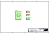
Figure 8. The same project CPU Design is easily viewed<br />
after import in the Projects panel of <strong>Altium</strong> <strong>Designer</strong>.<br />
In OrCAD Capture, net connectivity is made using net aliases, off-page connec<strong>to</strong>rs, hierarchical blocks<br />
and hierarchical ports, and globals. Nets between schematic pages within a single schematic folder are<br />
connected through the off-page connec<strong>to</strong>rs while the hierarchical blocks and ports connect the nets<br />
between the schematic folders. Globals are used <strong>to</strong> connect power/ground nets throughout the design.<br />
<strong>Altium</strong> <strong>Designer</strong> uses a similar set of net identifiers <strong>to</strong> create net connectivity. Within a schematic sheet<br />
you can use Wires and Net Labels. Between schematic sheets, nets in a flat design are typically<br />
connected using Ports, but Off-Sheet Connec<strong>to</strong>rs are also available. Nets in a hierarchical design are<br />
connected from a Port on the lower sheet <strong>to</strong> a Sheet Entry of the same name, in the sheet symbol that<br />
represents the lower sheet. Power/ground nets are connected using Power Ports.<br />
Configuring the design connectivity<br />
<strong>Altium</strong> <strong>Designer</strong> supports different types of design connectivity, and this must be set <strong>to</strong> suit the<br />
structure of the design. The type of sheet-<strong>to</strong>-sheet connectivity is referred <strong>to</strong> as the Net Identifier<br />
Scope. It is set in the Options tab of the Options for Project dialog, and saved with the project.<br />
<strong>From</strong> the Project menu select the Project Options menu command, and go <strong>to</strong> the Options tab, as<br />
shown in Figure 9.<br />
AP0132 (v2.1) February 21, 2006 9