
Create successful ePaper yourself
Turn your PDF publications into a flip-book with our unique Google optimized e-Paper software.
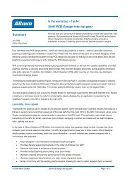
Summary<br />
Application Note<br />
AP0132 (v2.1) February 21, 2006<br />
<strong>Moving</strong> <strong>to</strong> <strong>Altium</strong> <strong>Designer</strong><br />
<strong>From</strong> OrCAD ®<br />
This application note highlights the key differences you need<br />
<strong>to</strong> be aware of when moving from OrCAD ® <strong>to</strong> <strong>Altium</strong><br />
<strong>Designer</strong>. It will help you ramp up your productivity and<br />
quickly take advantage of this powerful and flexible<br />
electronic product development environment.<br />
You’ve made the switch <strong>to</strong> <strong>Altium</strong> <strong>Designer</strong> – a single, unified application that incorporates all the<br />
technologies and capabilities necessary for complete electronic product development – and now you’re<br />
keen <strong>to</strong> get on with the design process. This application note gives you a jump start on the basics of<br />
designing in <strong>Altium</strong> <strong>Designer</strong>, and maps out the key differences you need <strong>to</strong> understand when moving<br />
from the OrCAD ® environment <strong>to</strong> <strong>Altium</strong> <strong>Designer</strong>. It also shows how easy it is <strong>to</strong> transfer your current<br />
OrCAD Capture ® and Layout ® designs and libraries in<strong>to</strong> <strong>Altium</strong> <strong>Designer</strong>.<br />
Getting started – transferring your OrCAD design<br />
Translating complete OrCAD designs, including Capture schematics, Layout PCB files, and library files<br />
can all be handled by <strong>Altium</strong> <strong>Designer</strong>’s Import Wizard. The Import Wizard removes much of the<br />
headache normally found with design translation by analyzing your files and offering many defaults and<br />
suggested settings for project structure, layer mapping, PCB footprint naming, and more. Complete<br />
flexibility is found in all pages of the Wizard, giving you as little or as much control as you would like<br />
over the file translation settings, before committing <strong>to</strong> the actual translation process.<br />
File translation<br />
Files in the Import Wizard translate as follows:<br />
• OrCAD Layout (*.MAX) files translate <strong>to</strong> <strong>Altium</strong> <strong>Designer</strong> PCB files (*.PcbDoc).<br />
• OrCAD Capture (*.DSN) files translate <strong>to</strong> <strong>Altium</strong> <strong>Designer</strong> schematic files. Each page within a .DSN<br />
file will be imported as a single <strong>Altium</strong> <strong>Designer</strong> schematic file (*.SchDoc). Design caches within a<br />
.DSN file will be imported as a schematic library (*.SchLib). Design hierarchy is maintained,<br />
including complex hierarchy.<br />
• These files will be grouped in<strong>to</strong> an <strong>Altium</strong> <strong>Designer</strong> PCB project (*.PrjPCB) that is au<strong>to</strong>matically<br />
created.<br />
OrCAD library files translate as follows:<br />
• OrCAD OLB (schematic library) files will be translated in<strong>to</strong> <strong>Altium</strong> <strong>Designer</strong> schematic library files<br />
(*.SchLib).<br />
• OrCAD LLB (PCB library) files will be translated in<strong>to</strong> <strong>Altium</strong> <strong>Designer</strong> PCB library files (*.PcbLib).<br />
• Translated OrCAD libraries are au<strong>to</strong>matically grouped in<strong>to</strong> one PCB project.<br />
AP0132 (v2.1) February 21, 2006 1
<strong>Moving</strong> <strong>to</strong> <strong>Altium</strong> <strong>Designer</strong> <strong>From</strong> OrCAD<br />
Pin Name and Number Movement in schematic<br />
It’s worthwhile <strong>to</strong> note as a matter of convenience that if you receive an Unrecognized Project File<br />
Version error after importing your designs, this error occurs due <strong>to</strong> the addition of a new feature <strong>to</strong><br />
OrCAD Capture v10.x, the ability <strong>to</strong> move pin names and numbers independently from the pin. If the<br />
OrCAD Capture schematic is saved normally it will be completely incompatible with OrCAD Capture 9.x<br />
and below, and also <strong>Altium</strong> <strong>Designer</strong>.<br />
To fix this problem you'll need access <strong>to</strong> OrCAD Capture v10.x. Make sure the DSN is selected in the<br />
project panel, then run File » Save As. You will see a small check box saying Remove Pin Name and<br />
Number Movement. This check box will appear if pin name and numbers have been moved in 10.x.<br />
Check it and save the DSN file.<br />
The DSN file can now be imported in<strong>to</strong> <strong>Altium</strong> <strong>Designer</strong>.<br />
Default Layer Mapping for PCB<br />
It should also be noted about how the layers are mapped on import for PCB designs. To facilitate the<br />
batch import process of multiple designs, there is Default Layer Mapping. The Default Layer Mapping<br />
is simply a mapping between the names of the foreign PCB layers and <strong>Altium</strong> <strong>Designer</strong> PCB layers. Of<br />
course you can add, change, or remove as many mappings as you want. This default mapping is then<br />
used by the import wizard <strong>to</strong> build the layer mapping for each PCB, that can then be individually<br />
cus<strong>to</strong>mized. The rationale here is that should you wish <strong>to</strong> import ten PCB designs and you want <strong>to</strong> map<br />
the layer Assembly 1 <strong>to</strong> Mechanical Layer 1, you would not have <strong>to</strong> cus<strong>to</strong>mize each of the ten PCB<br />
designs in order <strong>to</strong> get the right layer mapping.<br />
The advantage <strong>to</strong> importing in this manner is that batch management of layer mapping can save a lot<br />
of time when importing multiple designs. In this instance the default layer mapping will be saved <strong>to</strong> your<br />
preferences. The disadvantage <strong>to</strong> using this is that Default Layer Mapping is not always intelligent with<br />
differing structures in designs,<br />
and so some manual changes<br />
may be needed afterwards.<br />
You’ll need <strong>to</strong> decide what is<br />
best for your situation.<br />
Using the Import<br />
Wizard for OrCAD<br />
files<br />
The Import Wizard can be<br />
launched from the <strong>Altium</strong><br />
<strong>Designer</strong> File menu. Simply<br />
click on this menu command <strong>to</strong><br />
invoke the wizard, as shown in<br />
Figure 1. Right mouse click<br />
command menus are available<br />
for further control over the<br />
translation process through<br />
each page of the wizard.<br />
Figure 1. Import Wizard as started from the File Menu.<br />
2 AP0132 (v2.1) February 21, 2006
The <strong>Altium</strong> <strong>Designer</strong> Environment<br />
The <strong>Altium</strong> <strong>Designer</strong> environment offers a<br />
complete electronic product development<br />
environment for all areas of design – from<br />
schematic capture <strong>to</strong> the generation of<br />
PCB output, as well as complete FPGA<br />
design, development and on-chip<br />
debugging.<br />
Perhaps the single biggest difference that<br />
you will notice when you start working in<br />
<strong>Altium</strong> <strong>Designer</strong> is that there is only one<br />
application used <strong>to</strong> create and edit all<br />
design files, regardless of the type of file<br />
– schematics, PCB, library, text, and so<br />
on. No longer will you have <strong>to</strong> switch<br />
between different applications when you<br />
want <strong>to</strong> move from viewing the schematic<br />
<strong>to</strong> the PCB. All the files (also referred <strong>to</strong><br />
as documents) open in the same<br />
executable, each appearing on a<br />
separate document Tab within <strong>Altium</strong><br />
<strong>Designer</strong>. As you move from one type of<br />
document <strong>to</strong> another the menus and<br />
<strong>to</strong>olbars au<strong>to</strong>matically switch, giving you<br />
the right editing environment for that<br />
document.<br />
<strong>Altium</strong> <strong>Designer</strong> has full support for<br />
multiple moni<strong>to</strong>rs <strong>to</strong>o. If you have multiple<br />
moni<strong>to</strong>rs on your PC you can easily drag<br />
a document out of <strong>Altium</strong> <strong>Designer</strong> and<br />
drop it on the second moni<strong>to</strong>r, greatly<br />
enhancing your design productivity.<br />
<strong>Moving</strong> <strong>to</strong> <strong>Altium</strong> <strong>Designer</strong> <strong>From</strong> OrCAD<br />
To get you started let’s review some of the basic terminology that you’ll need <strong>to</strong> know as you work in<br />
<strong>Altium</strong> <strong>Designer</strong>.<br />
Working with documents<br />
Figure 2. Translated design files are displayed immediately after<br />
translation in the Projects panel. Once the project has been<br />
compiled the schematic hierarchy will be shown.<br />
In OrCAD Capture all design work begins on the page, the logical working area of the design. There<br />
can be multiple schematic pages within a single OrCAD schematic design file (.DSN file).<br />
In <strong>Altium</strong> <strong>Designer</strong>, the logical design area begins with a document, and for each document there is a<br />
file s<strong>to</strong>red on the hard drive. This means that for each <strong>Altium</strong> <strong>Designer</strong> schematic sheet (page) there is<br />
a file, an important conceptual difference <strong>to</strong> remember.<br />
AP0132 (v2.1) February 21, 2006 3
<strong>Moving</strong> <strong>to</strong> <strong>Altium</strong> <strong>Designer</strong> <strong>From</strong> OrCAD<br />
There can also be multiple design documents of varying types, depending on the nature of the design<br />
you are working on. Getting started, most OrCAD users will be interested in the schematic and PCB<br />
document types as these are the files that their designs will be translated <strong>to</strong> (see Figure 2).<br />
New schematic and PCB document types can easily be created via the File » New menu, or by rightclicking<br />
on the project in the Projects panel (Figure 6).<br />
Workspace panels<br />
Many elements of the environment will appear intuitive <strong>to</strong> OrCAD users, helping as you <strong>to</strong> start<br />
exploring the system. For example, the Projects panel will appear similar <strong>to</strong> the OrCAD Project<br />
Manager, except that since it is not limited <strong>to</strong> schematic design data it can include the PCB, all<br />
libraries, output files, as well as other project documents, such as MS Word or Excel files.<br />
You will also notice that your translated files will be grouped somewhat differently than you are used <strong>to</strong><br />
seeing. Whether you need <strong>to</strong> open a specific document such as a schematic, or need information or<br />
control <strong>to</strong> design on a more global, system-wide level, it can all be done using the Projects panel.<br />
As you open and make active the documents within various edi<strong>to</strong>rs you will notice that the resources<br />
and available panels will change dynamically; the menus, available panels, and <strong>to</strong>olbars will quickly<br />
change <strong>to</strong> match the document type you are currently focused on for editing. You’ll want <strong>to</strong> familiarize<br />
yourself with how <strong>to</strong> access these panels, manage, group, and control your display modes <strong>to</strong> get the<br />
most out of the productivity features that are provided here. Press F1 when the cursor is over a panel<br />
for more information on that panel.<br />
Where’s all my stuff? Some basics on s<strong>to</strong>rage management<br />
All design documents and generated output files, including your translated OrCAD design files, are<br />
s<strong>to</strong>red as individual files on your hard disk. Your design documents can be accessed by opening the<br />
project first and then opening the individual documents, or any individual document can be opened<br />
directly, using the File Open menu command.<br />
Projects panel<br />
<strong>Altium</strong> <strong>Designer</strong>, like OrCAD, also features project management capabilities but there are conceptual<br />
differences you’ll need <strong>to</strong> get firm in your mind first. The <strong>Altium</strong> <strong>Designer</strong> approach <strong>to</strong> managing your<br />
project is that all design documents (schematic, PCB, libraries, etc.) are linked <strong>to</strong> the project file, both<br />
for management and access <strong>to</strong> certain design features such as design verification, comparison, and<br />
synchronization. The <strong>Altium</strong> <strong>Designer</strong> presentation through the Projects panel provides high visibility<br />
and a complete view of everything you need in your project, not just the schematic part of it. The<br />
project file, which is what you are viewing in the Projects panel, contains links <strong>to</strong> all your documents in<br />
your design, as well as any other project-level definitions.<br />
The essentials of project-based design are discussed later in the Project-based design section.<br />
S<strong>to</strong>rage Manager<br />
<strong>Altium</strong> <strong>Designer</strong> features a dedicated S<strong>to</strong>rage Manager <strong>to</strong> allow you greater control over the<br />
management of files in your projects. The S<strong>to</strong>rage Manager can be invoked at any time simply by<br />
clicking on the System but<strong>to</strong>n at the bot<strong>to</strong>m of the <strong>Altium</strong> <strong>Designer</strong> application window and choosing<br />
S<strong>to</strong>rage Manager from the pop-up that appears.<br />
4 AP0132 (v2.1) February 21, 2006
Figure 3. The S<strong>to</strong>rage Manager.<br />
<strong>Moving</strong> <strong>to</strong> <strong>Altium</strong> <strong>Designer</strong> <strong>From</strong> OrCAD<br />
The S<strong>to</strong>rage Manager is multi-functional and can be used for everything from general everyday file<br />
management tasks such as renaming or deleting files, management of backups, through <strong>to</strong> integrating<br />
with your company’s version control system, as shown above in Figure 3.<br />
Refer <strong>to</strong> the document, Welcome <strong>to</strong> the <strong>Altium</strong> <strong>Designer</strong> Environment, for an introduction <strong>to</strong> <strong>Altium</strong><br />
<strong>Designer</strong> and an overview of its unique and unified environment. It provides an illustrated and easy<br />
approach <strong>to</strong> using Workspace panels, s<strong>to</strong>rage management, environment cus<strong>to</strong>mization and much<br />
more.<br />
Navigation <strong>to</strong>olbar – direct document navigation<br />
Because you can have many design documents and projects open at any time, <strong>Altium</strong> <strong>Designer</strong><br />
provides a Navigation <strong>to</strong>olbar <strong>to</strong> find the specific design you need quickly. Since everything is<br />
integrated in<strong>to</strong> <strong>Altium</strong> <strong>Designer</strong> there is no need <strong>to</strong> switch <strong>to</strong> another application when you need <strong>to</strong> view<br />
a different type of design file. The Navigation<br />
<strong>to</strong>olbar (Figure 4) is available <strong>to</strong> assist in the<br />
direct navigation of design documents, and<br />
can be accessed at any time from within any<br />
Figure 4. The Navigation Toolbar.<br />
of the document edi<strong>to</strong>rs.<br />
Browsing viewed documents<br />
The field at the left of the bar allows you <strong>to</strong> navigate <strong>to</strong> any direc<strong>to</strong>ry or document on a network or local<br />
s<strong>to</strong>rage directly, as well as any page on the internet. Browsing previously-viewed documents is easy<br />
using the left and right arrow but<strong>to</strong>ns <strong>to</strong> go forward and back through previous area, just as you would<br />
within an Internet Browser.<br />
AP0132 (v2.1) February 21, 2006 5
<strong>Moving</strong> <strong>to</strong> <strong>Altium</strong> <strong>Designer</strong> <strong>From</strong> OrCAD<br />
Integrated Navigation Home Page<br />
Click the Go <strong>to</strong> Home Page but<strong>to</strong>n <strong>to</strong> access the Integrated Navigation Home Page, a <strong>to</strong>p level<br />
page where all navigation support pages can be accessed, as shown in Figure 5.<br />
Figure 5. The Navigation Home Page.<br />
Favorites<br />
Like your internet browser, <strong>Altium</strong> <strong>Designer</strong> supports the concept of defining Favorites. Once the<br />
Favorites panel is displayed (click the System but<strong>to</strong>n on the Status line) you can right-click in the<br />
Favorites panel <strong>to</strong> mark the current view of the active document as a favorite. Simply double-click on a<br />
favorite <strong>to</strong> return <strong>to</strong> that document, zoomed <strong>to</strong> the exact area and location you require.<br />
As well as views of documents in your design, favorites can include links <strong>to</strong> any direc<strong>to</strong>ry or document<br />
on the network or local s<strong>to</strong>rage, as well as any page on the internet.<br />
Immediate access <strong>to</strong> Help<br />
For further information about the Favorites panel as well as many other <strong>to</strong>pics in <strong>Altium</strong> <strong>Designer</strong>, open<br />
the Knowledge Center panel (click the Help but<strong>to</strong>n on Status line). When the Knowledge Center<br />
panel is open it will au<strong>to</strong>-load help on the object, command, or menu entry currently under the cursor if<br />
you pause, or you can press F1 <strong>to</strong> load the <strong>to</strong>pic immediately.<br />
6 AP0132 (v2.1) February 21, 2006
Project-based design<br />
Now that we’ve covered some of the<br />
basics of the <strong>Altium</strong> <strong>Designer</strong><br />
environment, it is time <strong>to</strong> talk about<br />
designing. The starting point for every<br />
design created in <strong>Altium</strong> <strong>Designer</strong> is a<br />
project.<br />
It’s a simple and important concept –<br />
an <strong>Altium</strong> <strong>Designer</strong> project is a set of<br />
design documents whose output<br />
defines a single implementation. For<br />
example, the schematics and PCB in a<br />
PCB project output the fileset required<br />
<strong>to</strong> manufacture a single printed circuit<br />
board, while the schematics (and HDL)<br />
in an FPGA project output the fileset<br />
required <strong>to</strong> program a single FPGA.<br />
The project file brings <strong>to</strong>gether all of<br />
the design documents that make up<br />
the project.<br />
<strong>Altium</strong> <strong>Designer</strong> supports a number of<br />
different types of projects, including:<br />
PCB, FPGA, Embedded Projects,<br />
Core Projects, Integrated Libraries,<br />
and Script Projects.<br />
Back <strong>to</strong> the Projects panel<br />
<strong>Moving</strong> <strong>to</strong> <strong>Altium</strong> <strong>Designer</strong> <strong>From</strong> OrCAD<br />
In <strong>Altium</strong> <strong>Designer</strong>, all items related <strong>to</strong><br />
a project are linked <strong>to</strong> a Project<br />
document, and are easily accessible<br />
and manageable in one location. The<br />
Projects panel is one of the more Figure 6. Right-click <strong>to</strong> show all project-related commands.<br />
commonly-used panels in day <strong>to</strong> day<br />
work as it allows you <strong>to</strong> make changes <strong>to</strong> your project options, add <strong>to</strong> and remove documents from the<br />
project, change the display options of projects, change the order of documents within a project, or even<br />
how you would like <strong>to</strong> display information in the Projects panel.<br />
All of your translated design files will appear in the Projects panel, organized in<strong>to</strong> their respective<br />
projects that were au<strong>to</strong>matically created for them. Right-click on the project document <strong>to</strong> display a<br />
context-sensitive command menu, giving access <strong>to</strong> project-relevant editing commands (Figure 6).<br />
Refer <strong>to</strong> the application note Project Essentials for all the basics of creating project files, adding and<br />
removing files from a project, setting project options, as well as understanding the various project<br />
types. It also explains how <strong>to</strong> group related projects <strong>to</strong>gether in<strong>to</strong> a Workspace, ideal for managing<br />
multi-board projects.<br />
AP0132 (v2.1) February 21, 2006 7
<strong>Moving</strong> <strong>to</strong> <strong>Altium</strong> <strong>Designer</strong> <strong>From</strong> OrCAD<br />
Project hierarchy<br />
For any project involving multi-sheet design, there are basically two choices that need <strong>to</strong> be made –<br />
defining the structural relationship between the schematic sheets (flat or hierarchical), and determining<br />
the method of electrical connectivity between the circuitry on those sheets. Display of the project<br />
hierarchy in <strong>Altium</strong> <strong>Designer</strong>’s Projects panel is quite similar <strong>to</strong> OrCAD Capture’s Project Manager,<br />
with some differences in naming conventions and how hierarchies are graphically represented.<br />
Defining your sheet structure in OrCAD Capture’s Project Manager<br />
Like <strong>Altium</strong> <strong>Designer</strong>, Capture supports flat and hierarchical designs. Both use a block-like symbol <strong>to</strong><br />
define sheet-<strong>to</strong>-sheet structure in a hierarchical design, called a Sheet Symbol in <strong>Altium</strong> <strong>Designer</strong>, and<br />
a Hierarchical Block in Capture. In both the symbol references the lower level schematic. In <strong>Altium</strong><br />
<strong>Designer</strong> this is simply another schematic sheet, in Capture it can be more complex.<br />
Capture has another layer of design partitioning that affects hierarchy. In Capture there is a schematic,<br />
which present as a folder icon in Capture’s Project Manager, and there are pages, which present as a<br />
schematic sheet icon. Each Capture schematic can be made up of one or more pages. The Capture<br />
hierarchical block points <strong>to</strong> the schematic below, which means the block can actually reference circuitry<br />
divided over multiple pages.<br />
Typically a flat Capture design is one schematic (folder),<br />
with the design being drawn on as many pages as required<br />
in that schematic (folder). For a hierarchical design, the<br />
hierarchical block symbol (or part with an attached<br />
schematic sheet or model) is the mechanism used <strong>to</strong><br />
partition the major functional regions of a design.<br />
For a simple hierarchy, each hierarchical block, or part with<br />
an attached schematic folder, or VHDL model, represents a<br />
unique design module. The Hierarchy tab in OrCAD<br />
Capture’s Project Manager displays a simple hierarchical<br />
design as a tree of schematic pages. The schematic folder<br />
or VHDL entity at the <strong>to</strong>p of a hierarchy, which directly or<br />
indirectly refers <strong>to</strong> all other modules in the design, is called<br />
the root module. In the OrCAD Project Manager's File tab,<br />
the root module has a backslash on its folder icon (Figure<br />
7). The root module folder, as well as any other module<br />
folder, can contain as many schematic pages or VHDL<br />
models as required.<br />
Now let’s look at <strong>Altium</strong> <strong>Designer</strong>.<br />
Sheet structure in <strong>Altium</strong> <strong>Designer</strong>’s Projects panel<br />
Figure 7. The structure of an example<br />
CPU_Design project as it would appear in<br />
OrCAD Capture.<br />
In <strong>Altium</strong> <strong>Designer</strong>, hierarchical designs can likewise be viewed and navigated also as a tree structure<br />
through the Projects panels. Once the project has been compiled at least once, the Projects panel will<br />
show the hierarchical structure. In a hierarchical design you can think of the first sheet as the parent<br />
and those represented by sheet symbols as children (note that child sheets can have their own children<br />
<strong>to</strong>o). With that idea in mind, the tree view of the hierarchy makes it easy <strong>to</strong> navigate and get the overall<br />
8 AP0132 (v2.1) February 21, 2006
<strong>Moving</strong> <strong>to</strong> <strong>Altium</strong> <strong>Designer</strong> <strong>From</strong> OrCAD<br />
picture of your design, the hierarchy of the example CPU Design shown in Figure 7 is shown in Figure<br />
8 as it appears in <strong>Altium</strong> <strong>Designer</strong>.<br />
A multi-sheet design project in <strong>Altium</strong> <strong>Designer</strong><br />
can also be arranged as a hierarchical structure<br />
of logical blocks, where each block can be either<br />
a schematic sheet or a HDL file (VHDL or<br />
Verilog). At the head, or <strong>to</strong>p, of this tree structure<br />
is a single master schematic sheet, more<br />
commonly referred <strong>to</strong> as the project’s <strong>to</strong>p or<br />
parent sheet.<br />
The structure of the sheets is formed through the<br />
use of a special symbol called a sheet symbol.<br />
Each of the source documents that make up the<br />
design are represented on the parent sheet by a<br />
sheet symbol. The Filename property of each<br />
sheet symbol references the schematic subsheet<br />
that it graphically represents. In turn, a<br />
schematic sub-sheet can also contain further<br />
sheet symbols referencing lower schematic<br />
sheets or HDL files. In this way you can define a<br />
structural hierarchy of source documents that<br />
can be as simple or complex as your needs<br />
require.<br />
Defining your net connectivity – it is different<br />
Figure 8. The same project CPU Design is easily viewed<br />
after import in the Projects panel of <strong>Altium</strong> <strong>Designer</strong>.<br />
In OrCAD Capture, net connectivity is made using net aliases, off-page connec<strong>to</strong>rs, hierarchical blocks<br />
and hierarchical ports, and globals. Nets between schematic pages within a single schematic folder are<br />
connected through the off-page connec<strong>to</strong>rs while the hierarchical blocks and ports connect the nets<br />
between the schematic folders. Globals are used <strong>to</strong> connect power/ground nets throughout the design.<br />
<strong>Altium</strong> <strong>Designer</strong> uses a similar set of net identifiers <strong>to</strong> create net connectivity. Within a schematic sheet<br />
you can use Wires and Net Labels. Between schematic sheets, nets in a flat design are typically<br />
connected using Ports, but Off-Sheet Connec<strong>to</strong>rs are also available. Nets in a hierarchical design are<br />
connected from a Port on the lower sheet <strong>to</strong> a Sheet Entry of the same name, in the sheet symbol that<br />
represents the lower sheet. Power/ground nets are connected using Power Ports.<br />
Configuring the design connectivity<br />
<strong>Altium</strong> <strong>Designer</strong> supports different types of design connectivity, and this must be set <strong>to</strong> suit the<br />
structure of the design. The type of sheet-<strong>to</strong>-sheet connectivity is referred <strong>to</strong> as the Net Identifier<br />
Scope. It is set in the Options tab of the Options for Project dialog, and saved with the project.<br />
<strong>From</strong> the Project menu select the Project Options menu command, and go <strong>to</strong> the Options tab, as<br />
shown in Figure 9.<br />
AP0132 (v2.1) February 21, 2006 9
<strong>Moving</strong> <strong>to</strong> <strong>Altium</strong> <strong>Designer</strong> <strong>From</strong> OrCAD<br />
Figure 9. The Net Identifier scope is set in the Options tab of Project Options.<br />
In the Net Identifier Scope dropdown you can select from the following connectivity options:<br />
• Au<strong>to</strong>matic (Based on project contents)<br />
• Flat (Only ports global)<br />
• Hierarchical (Sheet entry port connections)<br />
• Global (Net labels and ports global)<br />
The Import Wizard handles connectivity au<strong>to</strong>matically through the translation process and will give you<br />
the Au<strong>to</strong>matic (Based on project contents) configuration by default. This option is simply an<br />
instruction <strong>to</strong> <strong>Altium</strong> <strong>Designer</strong>’s design compiler <strong>to</strong> determine which of the other three options are best<br />
suited for the connectivity in your design. Hierarchical blocks are mapped as sheet symbols, and they<br />
will translate <strong>to</strong> sheet symbols in <strong>Altium</strong> <strong>Designer</strong>. In Au<strong>to</strong>matic mode, the design compiler then looks<br />
at the sheet symbols on the <strong>to</strong>p sheet. If there are sheet entries (hierarchical pins) in them, it will<br />
assume vertical connectivity, and internally use the Hierarchical option. If there are no sheet symbols<br />
on the <strong>to</strong>p sheet, or if there are sheet symbols but they do not include any sheet entries, it will assume<br />
horizontal connectivity for which there are two ways that <strong>Altium</strong> <strong>Designer</strong> supports this: Flat and Global.<br />
In order <strong>to</strong> determine which of these two options <strong>to</strong> use, the design compiler looks for ports or off-sheet<br />
connec<strong>to</strong>rs on the subsheets. If there are any it uses the Flat option, if there are no ports it uses the<br />
Global option.<br />
Remember that you can easily go back and change this configuration after the translation process<br />
through the Project Options dialog from the Projects menu. The Import Wizard also allows OrCAD<br />
10 AP0132 (v2.1) February 21, 2006
<strong>Moving</strong> <strong>to</strong> <strong>Altium</strong> <strong>Designer</strong> <strong>From</strong> OrCAD<br />
users <strong>to</strong> determine how they want their junctions <strong>to</strong> import, and also log any errors or warnings that you<br />
can check later after importing.<br />
Defining net connectivity, net identifiers, scoping and how it all relates <strong>to</strong> multi-sheet design is a<br />
must read for OrCAD users and is fully explained in Connectivity and Multi-Sheet Design.<br />
Design synchronization<br />
Design synchronization is fully integrated in <strong>Altium</strong> <strong>Designer</strong> without the need for passing a net list.<br />
Synchronization in <strong>Altium</strong> <strong>Designer</strong> is also bi-directional, allowing you <strong>to</strong> make annotation changes and<br />
component property updates in both directions between your schematic and PCB, in a single<br />
operation.<br />
Again, an important and fundamental premise of <strong>Altium</strong> <strong>Designer</strong> is that the setup of the design's<br />
connectivity is driven from the schematic through <strong>to</strong> the PCB. If you are making connectivity changes in<br />
the opposite direction (from PCB <strong>to</strong> Schematic), a report is generated and these updates can then be<br />
performed on the schematic.<br />
The synchronization feature is used when you first transfer from the schematic <strong>to</strong> the new blank board,<br />
or when you make design changes that need <strong>to</strong> be passed over.<br />
For more information on design transfer and design synchronization, read the article Finding<br />
Differences and Synchronizing Designs.<br />
As well as being able <strong>to</strong> detect electrical differences, such as changed designa<strong>to</strong>rs, component values<br />
or net connectivity, <strong>Altium</strong> <strong>Designer</strong> also include a physical difference engine, which can find schematic<br />
and PCB layout changes – ideal for examining changes between different revisions of a board.<br />
Complex Hierarchy<br />
Complex hierarchy is the general term used throughout the industry <strong>to</strong> describe the process of using<br />
multiple instances of the same sheet in a schematic hierarchy. This important concept is supported by<br />
<strong>Altium</strong> <strong>Designer</strong> as well as OrCAD.<br />
Multi-channel design<br />
Traditionally, a design that included complex hierarchy had <strong>to</strong> go through a process of ‘flattening’ or<br />
‘expanding’ the hierarchy at some point, <strong>to</strong> uniquely instantiate every component and net. <strong>Altium</strong><br />
<strong>Designer</strong> does not need <strong>to</strong> do this, so this multiple-instantiation capability is referred <strong>to</strong> as multichannel<br />
design instead of complex hierarchy.<br />
Like complex hierarchy, multi-channel design is the ability <strong>to</strong> reference a child sheet multiple times. It<br />
can be done by placing multiple sheet symbols, each referencing the same sub-sheet, or it can be<br />
done by placing a single sheet-symbol and using the Repeat statement <strong>to</strong> generate an array of subsheets.<br />
This is built on the complex hierarchy architecture of multiple instances, but in this case the<br />
parent object is expanded by the design compiler at the time of compilation (discussed below).<br />
Multi-channel design also supports multiple levels. For example, a 32-channel design could be<br />
structured over two levels, having 4-banks of 8-channels, <strong>to</strong> create the final 32-channels. Additionally<br />
you can wire signals <strong>to</strong> either all of the channels or use a bus where one member of the bus goes <strong>to</strong><br />
each channel. <strong>Altium</strong> <strong>Designer</strong> is the only electronic design platform <strong>to</strong> offer this concept.<br />
There are several example multi-channel designs that come with <strong>Altium</strong> <strong>Designer</strong> that you may<br />
wish <strong>to</strong> look at. These include the Multi-Channel Mixer, Peak Detec<strong>to</strong>r and PortSwitcher, all three<br />
AP0132 (v2.1) February 21, 2006 11
<strong>Moving</strong> <strong>to</strong> <strong>Altium</strong> <strong>Designer</strong> <strong>From</strong> OrCAD<br />
designs can be found in the \Examples\Reference Design folder. Once you have opened one of the<br />
examples you should compile it, then look for the tabs at the bot<strong>to</strong>m of each schematic sheet.<br />
For more information on multi-channel designs, refer <strong>to</strong> the article Multi-Channel Design Concepts.<br />
Parametric multi-channel design<br />
Support for multi-channel design – designs where the same section of circuitry is repeated – is an<br />
outstanding strength of <strong>Altium</strong> <strong>Designer</strong>. The ability <strong>to</strong> be able <strong>to</strong> make each channel different by<br />
passing parameters <strong>to</strong> it from the parent sheet symbol is also supported, and is referred <strong>to</strong> as<br />
parametric hierarchy.<br />
Using parametric hierarchy you can parametrically define the component value, supporting the<br />
situation where a component does not have the same value in each channel. Parametric components<br />
are defined by declaring their value as a parameter of the sheet symbol above, and then referencing<br />
that parameter on the target component.<br />
A full tu<strong>to</strong>rial that shows how <strong>to</strong> create a multi-channel design in the Schematic Edi<strong>to</strong>r, including the<br />
use of sub-sheets, sheet symbols, and the Repeat command may be found in the tu<strong>to</strong>rial, Creating<br />
a Multi-channel Design.<br />
Compilation – a corners<strong>to</strong>ne of <strong>Altium</strong> <strong>Designer</strong><br />
Compilation is a corners<strong>to</strong>ne concept of the <strong>Altium</strong> <strong>Designer</strong> environment, and a fundamental<br />
difference from OrCAD. Compilation is a process that allows you <strong>to</strong> harness many powerful design<br />
features and can be done with your translated OrCAD schematics, or even just a net list. Compilation<br />
can also be done on other types of documents such as library documents (described later in this<br />
application note).<br />
When you select Compile Project from the Project menu the compilation process works out the<br />
structural relationships between the source schematic (or HDL) documents in the project, then<br />
determines the net-level connectivity within each sheet, and finally the connectivity between the sheets.<br />
All this component and connective intelligence from your schematics design is written in<strong>to</strong> an internal<br />
data structure that can then be used for many post-compilation activities, such as comparing and<br />
showing differences between schematics, parameter managing, parametric navigation of your design,<br />
cross probing back and forth between the schematics and PCB, and much more.<br />
Where are my nets and components from my design?<br />
You’re going <strong>to</strong> notice that connectivity is not as explicit in your design as it was before in OrCAD, but<br />
rather has <strong>to</strong> be extracted from the design using the compilation process. This is available through the<br />
right-click menu in the Project panel, or using the Project » Compile Project menu command.<br />
Once the design is compiled the sheet-level hierarchy, as well as all the components, nets and buses<br />
are displayed in the Naviga<strong>to</strong>r panel. <strong>From</strong> here you can easily locate any component, bus, net or pin<br />
throughout the entire design. And if you hold the Alt key as you click on an object in the Naviga<strong>to</strong>r<br />
panel it is highlighted on the PCB as well as the schematic – no longer will you need <strong>to</strong> inspect net lists<br />
<strong>to</strong> review design connectivity.<br />
12 AP0132 (v2.1) February 21, 2006
Verifying your design – expanded error checking<br />
<strong>Moving</strong> <strong>to</strong> <strong>Altium</strong> <strong>Designer</strong> <strong>From</strong> OrCAD<br />
Another benefit that results from compiling a project in <strong>Altium</strong> <strong>Designer</strong> is built-in error reporting. This is<br />
completely configurable for your needs and can be done before your project is compiled. Simply rightclick<br />
either on the project file and invoking the Project Options command, or also through the Project<br />
menu.<br />
The Error Reporting tab allows you <strong>to</strong> fully configure all the errors and warnings that you’d like <strong>to</strong> run<br />
before running a compile, as shown in Figure 10.<br />
Figure 10. Error Reporting tab in Project Options dialog.<br />
You may wish <strong>to</strong> get a better picture of the entire development cycle and how it unfolds from an<br />
engineer’s perspective by reading An Overview of Electronic Product Development in <strong>Altium</strong><br />
<strong>Designer</strong>.<br />
The schematic symbol is the part…<br />
As an expert OrCAD user, you’ll know that parts form the basic building blocks of design in OrCAD.<br />
In OrCAD Layout (PCB), a part can represent one or more physical components; or it may represent a<br />
function, or simulation model. The part’s inherent behavior is described through a simulation model, or<br />
other means. Parts in PCB designs usually correspond <strong>to</strong> physical objects: gates, chips, connec<strong>to</strong>rs,<br />
objects that come in packages of one of more parts. Multiple-part packages are physical objects that<br />
are comprised of one or more parts.<br />
AP0132 (v2.1) February 21, 2006 13
<strong>Moving</strong> <strong>to</strong> <strong>Altium</strong> <strong>Designer</strong> <strong>From</strong> OrCAD<br />
In OrCAD’s Capture, a part is a logical entity that is described by symbol graphics, pins and various<br />
properties. As parts are placed in a schematic design, Capture maintains the identity of the part for<br />
back annotation, net listing, bills of materials, and so forth. At the very minimum, a part requires a part<br />
name, a part reference prefix, and a name of a PCB footprint.<br />
These two definitions that use the same term depending on the context of design may initially cause<br />
some confusion in the new environment which uses the term component instead. But it is not unlike<br />
how things work in <strong>Altium</strong> <strong>Designer</strong> except that the schematic symbol is effectively the component for<br />
all phases of design, and not just the schematic capture portion of it.<br />
<strong>Altium</strong> <strong>Designer</strong> components<br />
1..n<br />
=<br />
Multiple footprints<br />
<strong>Altium</strong> <strong>Designer</strong> Component<br />
=<br />
1..255<br />
symbols<br />
Multiple Simulation / 3D /<br />
SI models<br />
Figure 11. <strong>Altium</strong> <strong>Designer</strong> symbols can have multiple footprints and symbol models.<br />
In <strong>Altium</strong> <strong>Designer</strong>, the logical symbol is assumed <strong>to</strong> be the essential starting point of a component. It<br />
can be initially defined at minimum as a name in a schematic library <strong>to</strong> which pins and any graphical<br />
symbols or alternative display options needed for implementation may be added. This flexibility allows<br />
a component <strong>to</strong> be represented in different ways during the design and capture process. This may not<br />
only be as a logical symbol on the schematic, but also be a footprint on the PCB or even as a SPICE<br />
definition for simulation.<br />
The fundamentals of how components are defined, their properties, and basic relationships<br />
between components, models and library concepts are explained further in Component, Model, and<br />
Library Concepts.<br />
14 AP0132 (v2.1) February 21, 2006<br />
=<br />
1..n
Libraries<br />
<strong>Moving</strong> <strong>to</strong> <strong>Altium</strong> <strong>Designer</strong> <strong>From</strong> OrCAD<br />
<strong>Altium</strong> <strong>Designer</strong> supports working directly from the source symbol or model libraries, an ideal approach<br />
when the schematic and PCB are designed by separate organizations. There are also integrated<br />
libraries, a concept that will be new for OrCAD users. All libraries may be viewed and managed at any<br />
time from the Projects and Library Panels.<br />
<strong>Altium</strong> <strong>Designer</strong> Libraries<br />
An integrated library in <strong>Altium</strong> <strong>Designer</strong> is one where the source symbol, footprint, and all other<br />
information (e.g. SPICE and other model files) are compiled in<strong>to</strong> a single file. During compilation<br />
checks are made <strong>to</strong> see how relationships are defined, <strong>to</strong> validate the relationship between the models<br />
and the symbols and <strong>to</strong> bundle them in<strong>to</strong> a single integrated library. This file can not be directly edited<br />
after compilation, offering portability and security.<br />
All of <strong>Altium</strong> <strong>Designer</strong>’s 70,000+ components are supplied in integrated libraries, from which the source<br />
libraries can be extracted at any time if required.<br />
Library Types<br />
There are four types of libraries used in the <strong>Altium</strong> <strong>Designer</strong> environment: model, schematic, integrated<br />
and database.<br />
Model<br />
These libraries contain the models for each component representation as per their design domain and<br />
are each s<strong>to</strong>red in their respective “model containers”, called model libraries. In some domains, there<br />
will be typically one model per file and they are referred <strong>to</strong> as model files (*.mdl, *.ckt). In other design<br />
domains, models are usually grouped in<strong>to</strong> library files according <strong>to</strong> how the user has grouped them<br />
such as PCB footprints grouped in<strong>to</strong> package-type libraries (*.PcbLib).<br />
Schematic<br />
These libraries contain source schematic components and their model interface definitions (*SchLib).<br />
Integrated<br />
An integrated library (*.IntLib) is a compiled file, that includes schematic libraries along with all models<br />
referenced in the symbols’ model interface definitions; which could include footprint model libraries,<br />
simulation model files, and 3 dimensional model libraries.<br />
Database<br />
Database libraries provide similar functionality <strong>to</strong> the OrCAD Capture CIS. When you place from an<br />
installed database library (*DBLib) all data in the component comes from the referenced database.<br />
Where are my libraries? Some basics on library management<br />
You’ll be able <strong>to</strong> view your source schematic and PCB library files immediately after translation through<br />
the Projects panel. Your translated OrCAD libraries are au<strong>to</strong>matically grouped in<strong>to</strong> one PCB project.<br />
Like Capture, libraries are installed (added) <strong>to</strong> the <strong>Altium</strong> <strong>Designer</strong> environment, making their<br />
components available in all open projects. Display the Libraries panel, from there you can install and<br />
AP0132 (v2.1) February 21, 2006 15
<strong>Moving</strong> <strong>to</strong> <strong>Altium</strong> <strong>Designer</strong> <strong>From</strong> OrCAD<br />
remove libraries. Libraries can also be linked <strong>to</strong> any project, and you can also define project search<br />
paths, useful for referencing simulation models.<br />
Refer <strong>to</strong> the article Enhanced Library Management Using Integrated Libraries for a further<br />
discussion on using Integrated Libraries.<br />
A brief note on database linking<br />
Appreciating the fact that many designers like <strong>to</strong> link from the components in their electronic design<br />
software <strong>to</strong> their company database, <strong>Altium</strong> <strong>Designer</strong> has strong support for linking and transferring<br />
database data through the design process and in<strong>to</strong> the Bill of Materials.<br />
Two techniques are supported, one where the <strong>Altium</strong> <strong>Designer</strong> library symbol holds all model<br />
references and also includes links in<strong>to</strong> an external database, the second where the database holds all<br />
model references and other company information. While database connections in <strong>Altium</strong> <strong>Designer</strong> are<br />
set up for MS Access databases (*.mdb files) by default, any ODBC-compliant database can be<br />
accessed, offering the same flexibility you previously had with OrCAD.<br />
To learn more about linking from <strong>Altium</strong> <strong>Designer</strong> components <strong>to</strong> an external database, refer <strong>to</strong> the<br />
application note Linking Existing Components <strong>to</strong> Your Company Database.<br />
For information on placing components directly from a company component database, read the<br />
application note Using Components Directly from Your Company Database.<br />
How do I setup this new workspace? Designing the PCB<br />
A complete tu<strong>to</strong>rial that covers all the basics of PCB design transfer, including the <strong>to</strong>pics mentioned<br />
and much more can be found in Getting Started with PCB Design.<br />
PCB Board Wizard<br />
Before you can transfer your design from the Schematic Edi<strong>to</strong>r <strong>to</strong> the PCB Edi<strong>to</strong>r, you’ll need <strong>to</strong> have at<br />
the very least a blank PCB with at least a board outline. The PCB Board Wizard allows you <strong>to</strong> easily<br />
create a basic PCB design using many industry-standard board outlines as well as create your own<br />
cus<strong>to</strong>m board sizes.<br />
The PCB Board Wizard is invoked from the Files panel in the New from template section. At any<br />
stage you can use the Back but<strong>to</strong>n <strong>to</strong> check or modify previous pages in the wizard.<br />
Placement Grid and Units<br />
All options for the placement grid, measurement units, sheet position, and designa<strong>to</strong>r display may be<br />
found here. With a PCB document active in the main design window (for this and all of the following<br />
context-sensitive dialogs), select from the main menu commands Design » Board Options [shortcut<br />
D, O] <strong>to</strong> open the Board Options dialog.<br />
PCB Preferences<br />
Preferences that assist in positioning components easier such as Online DRC, Snap <strong>to</strong> Center,<br />
Selection preferences may be found by invoking the Preferences dialog for PCB Documents. Select<br />
Tools » Preferences [shortcut T, P] from the main menu command <strong>to</strong> open the Preferences dialog.<br />
16 AP0132 (v2.1) February 21, 2006
Board Layers and Colors<br />
<strong>Moving</strong> <strong>to</strong> <strong>Altium</strong> <strong>Designer</strong> <strong>From</strong> OrCAD<br />
Select Design » Board Layers and Colors [shortcut L] from the main menu command <strong>to</strong> display this<br />
dialog where you can display, add, remove, rename, and set the colors of the layers. It’s worth<br />
mentioning that you can easily navigate between the layers of your design simply by selecting the layer<br />
tabs at the bot<strong>to</strong>m of the main design window.<br />
Layer Stack Manager<br />
Layers can be easily managed and seen with the Layer Stack Manager. This dialog is easily accessed<br />
again from the main command menu Design » Layer Stack Manager [shortcut D, K]. Some other<br />
helpful shortcut keys from the numeric keypad include the ‘+’ and ‘–‘for cycling through all visible<br />
layers, and the ‘ * ‘<strong>to</strong> cycle through visible signal layers.<br />
For further information on setting up your board, refer <strong>to</strong> the tu<strong>to</strong>rial Preparing the Board for Design<br />
Transfer.<br />
Design Rules<br />
The PCB Edi<strong>to</strong>r is a powerful and dynamic rules-driven environment. This means that as you work in<br />
the PCB Edi<strong>to</strong>r and do things that change the design (such as placing tracks, moving components, or<br />
routing the board), the PCB Edi<strong>to</strong>r constantly moni<strong>to</strong>rs each action and checks <strong>to</strong> see if the design still<br />
complies with the design rules. If it doesn’t, an error is immediately flagged for your attention.<br />
With the PCB as the active document, select Design » Rules from the main command menu <strong>to</strong> invoke<br />
the PCB Rules and Constraint Edi<strong>to</strong>r dialog as shown below in Figure 12.<br />
Figure 12. The PCB Rules and Constraint Edi<strong>to</strong>r where all design rules can be managed.<br />
AP0132 (v2.1) February 21, 2006 17
<strong>Moving</strong> <strong>to</strong> <strong>Altium</strong> <strong>Designer</strong> <strong>From</strong> OrCAD<br />
One of the powerful features of <strong>Altium</strong> <strong>Designer</strong>’s design rule system is that multiple rules of the same<br />
type can be defined, each targeting different objects. This is called scoping, a new concept for OrCAD<br />
users, it allows you <strong>to</strong> exactly target rules <strong>to</strong> objects in your design. To say it another way, the exact set<br />
of objects that each rule targets is defined by that rule’s scope. The hierarchy of rules is also userdefined<br />
– this is the priority setting that you can see in Figure 12. This combination of rule scoping and<br />
priority gives an unprecedented level of control that allows you <strong>to</strong> precisely target the design rules for<br />
your board.<br />
Interactive Route<br />
As with OrCAD, you must have a signal layer active before you can begin routing. Enable the layer that<br />
you would like <strong>to</strong> start on by pressing the L shortcut key <strong>to</strong> display the Board Layers and Colors dialog.<br />
Click on the Show checkbox <strong>to</strong> enable a layer. Once you have enabled your signal layer, the tab for it<br />
will display in the main design window. Click on the Layer tab at the bot<strong>to</strong>m of the workspace <strong>to</strong> make it<br />
the current or active layer, ready <strong>to</strong> route on.<br />
Interactive Routing in <strong>Altium</strong> <strong>Designer</strong> can be invoked through either the Place command in the main<br />
menu, selecting the Interactive Routing command, or simply selecting the but<strong>to</strong>n in the Wiring<br />
<strong>to</strong>olbar.<br />
The following tips will assist you <strong>to</strong> get a quick start for placing traces:<br />
• Left-click or ENTER key – Places a start or end vertex in the trace. Placed trace segments will<br />
show in the appropriate layer color.<br />
• SPACEBAR – Allows you <strong>to</strong> <strong>to</strong>ggle between the start and end modes for the trace you are placing.<br />
• SHIFT+SPACEBAR – Allows you <strong>to</strong> change the corner mode of your current route<br />
• END – Allows you <strong>to</strong> redraw the screen at any time.<br />
• Shortcut keys V, F – Redraw the screen <strong>to</strong> fit all objects (View Extent).<br />
• PAGEUP, PAGEDOWN – Allow you <strong>to</strong> zoom in or out, centered on the cursor position. The mouse<br />
wheel will help you <strong>to</strong> pan left and right, holding the Ctrl key down <strong>to</strong> zoom in and out with the<br />
mouse wheel.<br />
• BACKSPACE – Will let you unplace the last trace segment.<br />
• Right-click or ESC – Will complete your trace.<br />
Display the Shortcuts panel for a dynamic list of shortcut keys available for use wherever you are<br />
currently working in <strong>Altium</strong> <strong>Designer</strong>, including context-sensitive shortcuts available while running a<br />
command. The Shortcuts panel can be enabled by clicking the Help but<strong>to</strong>n in the Status line.<br />
Situs Au<strong>to</strong>router<br />
The Situs <strong>to</strong>pological au<strong>to</strong>routing system is fully integrated in<strong>to</strong> <strong>Altium</strong> <strong>Designer</strong>. Once your active PCB<br />
document is completed and everything positioned, you’re ready <strong>to</strong> start.<br />
Select Au<strong>to</strong> Route » All, from the Situs Routing Strategies <strong>to</strong> select a suitable routing strategy, and<br />
then click on Route All <strong>to</strong> start au<strong>to</strong>routing. The Messages panel displays the routing progress.<br />
Routing a board can be a big challenge. For further points on your board setup, configuring your<br />
design rules, and running the router, take a look at the article Situs Au<strong>to</strong>routing Essentials.<br />
18 AP0132 (v2.1) February 21, 2006
Signal Integrity<br />
<strong>Moving</strong> <strong>to</strong> <strong>Altium</strong> <strong>Designer</strong> <strong>From</strong> OrCAD<br />
Signal Integrity is also integrated in<strong>to</strong> <strong>Altium</strong> <strong>Designer</strong>. Because of this, it requires that you have at the<br />
very least, a project file that contains at least one SCH source document. Signal Integrity is run from<br />
the main menu command Tools » Signal Integrity where the Model Assignments Analyses dialog will<br />
launch before Signal Integrity will run.<br />
A full tu<strong>to</strong>rial that covers the setting up of design parameters like design rules, and Signal Integrity<br />
models, starting up Signal Integrity from the SCH and PCB Edi<strong>to</strong>rs, and configuring your tests<br />
further can be found in the tu<strong>to</strong>rial Performing Signal Integrity Analyses.<br />
So how do I get my board manufactured? Setting up project outputs<br />
The setting up of all project outputs is consolidated through a single interface – the OutputJobs<br />
Edi<strong>to</strong>r. Because the output settings are s<strong>to</strong>red in a document (*.OutJob) it offers the convenience of<br />
being portable between multiple and different projects.<br />
OutputJobs Edi<strong>to</strong>r<br />
The OutputJobs Edi<strong>to</strong>r allows you <strong>to</strong> define and manage Output Job Configuration files (*.OutJob). The<br />
Output Job file allows you <strong>to</strong> define all your design output configurations – assembly, fabrication,<br />
reports, netlists, etc, all in a single location. You can even create multiple Output Job Files and add<br />
them <strong>to</strong> your project, for example <strong>to</strong> create a separate assembly output from the fabrication output.<br />
You can create a new file of this type for any active project by using either the File » New » Output<br />
Job File (as shown in Figure 13) command or right-clicking on a project in the Projects panel and<br />
choosing Add New <strong>to</strong> Project » Output Job File from the pop-up menu that appears.<br />
Figure 13. Fabrication output job file for the Multi-Channel Mixer project.<br />
The Output Job file is divided in<strong>to</strong> a number of categories that reflect the function of the output. These<br />
include Assembly, Documentation, Fabrication, Netlist, and Report Outputs. You’ll want <strong>to</strong> familiarize<br />
yourself with how <strong>to</strong> configure for the output options that you require.<br />
A comprehensive technical reference for setting up and configuring your output jobs through the<br />
OutputJobs Edi<strong>to</strong>r may be found in the OutputJob Edi<strong>to</strong>r Reference. You can open this by pressing<br />
F1 when the cursor is over an open OutputJob.<br />
AP0132 (v2.1) February 21, 2006 19
<strong>Moving</strong> <strong>to</strong> <strong>Altium</strong> <strong>Designer</strong> <strong>From</strong> OrCAD<br />
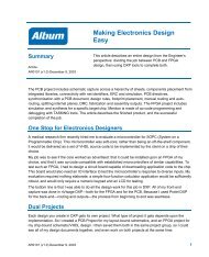
Smart PDF<br />
Smart PDF is a built-in PDF generation wizard that quickly generates a PDF of a single schematic<br />
sheet, drawings of the PCB, or all the schematics and PCB in a project, complete with clickable<br />
bookmarks <strong>to</strong> each component, net and pin in your design.<br />
The <strong>Altium</strong> <strong>Designer</strong> Smart PDF wizard is launched from the File menu, and will guide you through the<br />
steps required <strong>to</strong> export a design <strong>to</strong> PDF.<br />
Figure 14.Use Smart PDF <strong>to</strong> generate live, bookmarked PDFs of your designs, ideal for design reviews and product<br />
documentation.<br />
Viewer Edition License<br />
A viewer edition license is also available <strong>to</strong> replace the OrCAD viewer that you may have used before<br />
for design exploration and as a cross probing <strong>to</strong>ol, putting the right set of functionality in<strong>to</strong> the hands of<br />
designers and engineers across your organization.<br />
The Viewer Edition licensing option of <strong>Altium</strong> <strong>Designer</strong> provides quick, easy, and secure read-only<br />
exploration of design projects and documents that have been created using <strong>Altium</strong> <strong>Designer</strong>. Users<br />
can view, print and interrogate all aspects of a design created by <strong>Altium</strong> <strong>Designer</strong> making design data<br />
more accessible through the entire design-chain. The Viewer Edition not only enhances collaboration<br />
within an organization, but also between the design team and external parties, greatly improving design<br />
work flow and project productivity.<br />
20 AP0132 (v2.1) February 21, 2006
<strong>Moving</strong> <strong>to</strong> <strong>Altium</strong> <strong>Designer</strong> <strong>From</strong> OrCAD<br />
The <strong>Altium</strong> <strong>Designer</strong> Viewer Edition is provided free of charge. You can deploy the Viewer Edition<br />
across your organization using your existing <strong>Altium</strong> <strong>Designer</strong> license. For non-license holders, simply<br />
contact your nearest <strong>Altium</strong> sales office <strong>to</strong> apply for a Viewer Edition license. The license is activated<br />
online and registered <strong>to</strong> the user every 12 months.<br />
For further reference<br />
Below are references <strong>to</strong> other articles and tu<strong>to</strong>rials in the <strong>Altium</strong> <strong>Designer</strong> Documentation Library that<br />
talk more about the conceptual information as well as walking you through specific tasks. Remember,<br />
you can also browse through the Help contents, and use F1 and What’s This at any time in a dialog<br />
for more details.<br />
For more PCB project options, refer <strong>to</strong> the tu<strong>to</strong>rial, Getting Started with PCB Design.<br />
For more FPGA project options, refer <strong>to</strong> the tu<strong>to</strong>rial, Getting Started with FPGA Design.<br />
For a tu<strong>to</strong>rial that steps you through all the basics of creating components, read Creating Library<br />
Components.<br />
For a tu<strong>to</strong>rial that steps you through all the basics of editing multiple objects, read Editing Multiple<br />
Objects.<br />
For an overview of <strong>Altium</strong> <strong>Designer</strong>’s FPGA design, development and debugging capabilities refer<br />
<strong>to</strong> the FPGA <strong>Designer</strong>s QuickStart Guide.<br />
For getting started with embedded software, refer <strong>to</strong> Getting Started with Embedded Software.<br />
Revision His<strong>to</strong>ry<br />
Date Version No. Revision<br />
2-Feb-2006 2.0 New document release<br />
21-Feb-2006 2.1 Content reviewed and updated<br />
Software, documentation and related materials:<br />
Copyright © 2006 <strong>Altium</strong> Limited.<br />
All rights reserved. You are permitted <strong>to</strong> print this document provided that (1) the use of such is for<br />
personal use only and will not be copied or posted on any network computer or broadcast in any<br />
media, and (2) no modifications of the document is made. Unauthorized duplication, in whole or part, of<br />
this document by any means, mechanical or electronic, including translation in<strong>to</strong> another language,<br />
except for brief excerpts in published reviews, is prohibited without the express written permission of<br />
<strong>Altium</strong> Limited. Unauthorized duplication of this work may also be prohibited by local statute. Viola<strong>to</strong>rs<br />
may be subject <strong>to</strong> both criminal and civil penalties, including fines and/or imprisonment. <strong>Altium</strong>, <strong>Altium</strong><br />
<strong>Designer</strong>, Board Insight, CAMtastic, CircuitStudio, Design Explorer, DXP, LiveDesign, NanoBoard,<br />
NanoTalk, Nexar, nVisage, P-CAD, Protel, Situs, TASKING, and Topological Au<strong>to</strong>routing and their<br />
respective logos are trademarks or registered trademarks of <strong>Altium</strong> Limited or its subsidiaries. All other<br />
registered or unregistered trademarks referenced herein are the property of their respective owners<br />
and no trademark rights <strong>to</strong> the same are claimed.<br />
AP0132 (v2.1) February 21, 2006 21