Anleitungen - Wunderlich
Anleitungen - Wunderlich
Anleitungen - Wunderlich

You also want an ePaper? Increase the reach of your titles
YUMPU automatically turns print PDFs into web optimized ePapers that Google loves.
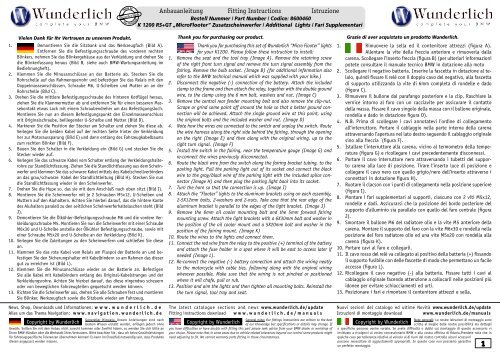
Vielen Dank für Ihr Vertrauen zu unserem Produkt.<br />
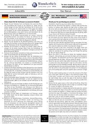
1. Demontieren Sie die Sitzbank und das Werkzeugfach (Bild A).<br />
Entfernen Sie die Befestigungsschraube des vorderen rechten<br />
Blinkers, nehmen Sie das Blinkergehäuse aus der Verkleidung und drehen Sie<br />
die Blinkerfassung heraus (Bild B, siehe auch BMW-Wartungsanleitung im<br />
Bediehnungheft).<br />
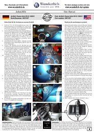
2. Klemmen Sie die Minusanschlüsse an der Batterie ab. Stecken Sie die<br />
Rohrschelle auf das Rahmenquerrohr und befestigen Sie das Relais mit den<br />
Doppelmasseanschlüssen, Schraube M6, U-Scheiben und Mutter an an der<br />
Rohrschelle (Bild C).<br />
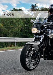
3. Drehen Sie die mittlere Befestigungsschraube des hinteren Kotflügel heraus,<br />
ziehen Sie die Klammermutter ab und entfernen Sie für einen besseren Massekontakt<br />
etwas Lack mit einem Schraubendreher um das Befestigungsloch.<br />
Montieren Sie nun an diesem Befestigungspunkt den Einzelmasseanschluss<br />
mit Originalschraube, beiliegender U-Scheibe und Mutter (Bild D).<br />
4. Markieren Sie die Position der Stecker am Schalter und ziehen Sie diese ab.<br />
Verlegen Sie die beiden Kabel auf der rechten Seite hinter der Verkleidung<br />
her zur Motoraussparung (Bild E) und dann entlang des Fahrzeugkabelbaums<br />
zum rechten Blinker (Bild F).<br />
5. Bauen Sie den Schalter in die Verkleidung ein (Bild G) und stecken Sie die<br />
Stecker wieder auf.<br />
6. Verlegen Sie das schwarze Kabel vom Schalter entlang der Verkleidungshalterohre<br />
zur Standlichtfassung. Ziehen Sie die Standlichtfassung aus dem Scheinwerfer<br />
und klemmen Sie das schwarze Kabel mittels des Kabelschnellverbinders<br />
an das grau/schwarze Kabel der Standlichtleitung (Bild H). Stecken Sie nun<br />
die Standlichtfassung wieder in den Scheinwerfer.<br />
7. Drehen Sie die Hupe so, das sie mit dem Anschluß nach oben sitzt (Bild I).<br />
8. Montieren Sie die Scheinwerfer mit je 2 Schrauben M5x12, U-Scheiben und<br />
Muttern auf den Aluhaltern. Achten Sie hierbei darauf, das die hintere Kante<br />
des Aluhalters paralell zu den seitlichen Scheinwerferhaltelaschen steht (Bild<br />
J).<br />
9. Demontieren Sie die Ölkühler-Befestigungsschraube M6 und die vordere Verkleidungsschraube<br />
M5. Montieren Sie nun die Scheinwerfer mit einer Schraube<br />
M6x30 und U-Scheibe anstelle der Ölkühler Befestigungsschraube, sowie mit<br />
einer Schraube M5x20 und U-Scheibe an der Verkleidung (Bild K).<br />
10. Verlegen Sie die Zuleitungen zu den Scheinwerfern und schließen Sie diese<br />
an.<br />
11. Klemmen Sie das rote Kabel vom Relais am Pluspol der Batterie an und befestigen<br />
Sie den Sicherungshalter mit Kabelbindern so am Rahmen das dieser<br />
gut zu erreichen ist (Bild L).<br />
12. Klemmen Sie die Minusanschlüsse wieder an der Batterie an. Befestigen<br />
Sie alle Kabel mit Kabelbindern entlang des Original-Kabelstranges und der<br />
Verkleidungsrohre. Achten Sie hierbei darauf, das diese nirgendwo scheuern<br />
oder von beweglichen Fahrzeugteilen gequetscht werden können.<br />
13. Richten Sie die Scheinwerfer aus, drehen Sie alle Schrauben fest und montieren<br />
Sie Blinker, Werkzeugfach sowie die Sitzbank wieder am Fahrzeug.<br />
News, Shop, Downloads und Informationen: w w w . w u n d e r l i c h . d e<br />
Alles um das Thema Navigation: w w w . n a v i g a t i o n . w u n d e r l i c h . d e<br />
Genereller Hinweis: Unsere <strong>Anleitungen</strong> sind nach<br />
bestem Wissen erstellt worden, erfolgen jedoch ohne<br />
Gewähr. Sollten Sie mit dem Anbau nicht zurecht kommen oder Zweifel haben, so wenden Sie sich bitte an<br />
Ihren BMW-Händler oder die Werkstatt Ihres Vertrauens. Bitte beachten Sie , dass wir keine Gewährleistungen<br />
für fahrzeugspezifische Toleranzen übernehmen können! Es kann im Einzelfall notwendig sein, dass Produkte<br />
diesen angepasst werden müssen.<br />
Copyright by <strong>Wunderlich</strong> Copyright by <strong>Wunderlich</strong><br />
Anbauanleitung Fitting Instructions Istruzione<br />
Bestell Nummer / Part Number / Codice: 8600460<br />
K 1200 RS+GT „MicroFlooter“ Zusatzscheinwerfer / Additional Lights / Fari Supplementari<br />
Thank you for purchasing our product. Grazie di aver acquistato un prodotto <strong>Wunderlich</strong>.<br />
Thank you for purchasing this set of <strong>Wunderlich</strong> “Micro Flooter” lights<br />
for your K1200. Please follow these instruction to install:<br />
1. Remove the seat and the tool tray (Image A). Remove the retaining screw<br />
of the right front turn signal and remove the turn signal assembly from the<br />
fairing. Remove the bulb socket. (Image B) (for additional information also<br />
refer to the BMW technical manual which was supplied with your bike.)<br />
2. Disconnect the negative (-) connection of the battery. Attach the included<br />
clamp to the frame and then attach the relay, together with the double ground<br />
wire, to the clamp using the 6 mm bolt, washers and nut. (Image C)<br />
3. Remove the central rear fender mounting bolt and also remove the clip-nut.<br />
Scrape or grind some paint off around the hole so that a better ground connection<br />
will be achieved. Attach the single ground wire at this point, using<br />
the original bolts and the included washer and nut. (Image D)<br />
4. Note how the wires are connected to the switch and unplug the switch. Route<br />
the wire harness along the right side behind the fairing, through the opening<br />
on the right (Image E) and then along with the original wiring, up to the<br />
right turn signal. (Image F)<br />
5. Install the switch in the fairing, near the temperature gauge (Image G) and<br />
re-connect the wires previously disconnected.<br />
6. Route the black wire from the switch along the fairing bracket tubing, to the<br />
parking light. Pull the parking light out of its socket and connect the black<br />
wire to the gray/black wire of the parking light with the included splice connector<br />
(Image H) and then plug the parking light back into its socket.<br />
7. Turn the horn so that the connection is up. (Image I)<br />
8. Attach the “Flooter” lights to the aluminum brackets using on each assembly,<br />
2-5X12mm bolts, 2-washers and 2-nuts. Take care that the rear edge of the<br />
aluminum bracket is parallel to the edges of the light bracket. (Image J)<br />
9. Remove the 6mm oil cooler mounting bolt and the 5mm forward fairing<br />
mounting screw. Attach the light brackets with a 6X30mm bolt and washer in<br />
the position of the oil cooler mount and a 5X20mm bolt and washer in the<br />
position of the fairing mount. (Image K)<br />
10. Route the wires to the lights and connect them.<br />
11. Connect the red wire from the relay to the positive (+) terminal of the battery<br />
and attach the fuse holder in a spot where it will be east to access later if<br />
needed (Image L).<br />
12. Re-connect the negative (-) battery connection and attach the wiring neatly<br />
to the motorcycle with cable ties, following along with the original wiring<br />
wherever possible. Make sure that the wiring is not pinched or positioned<br />
where it will chafe, pull or rub.<br />
13. Position and aim the lights and then tighten all mounting bolts. Reinstall the<br />
the turn signal, tool tray and seat.<br />
The latest catalogue sections and news www.wunderlich.de/update<br />
Fitting instructions download w w w . w u n d e r l i c h . d e / m a n u a l s<br />
General note: Our fittings instructions are written to the best<br />
of our knowledge but specifications or details may change. If<br />
you have difficulties or have doubts with fitting this part please seek advice from your BMW dealer or workshop of<br />
your choice. Please note that in some cases due to vehicle related tolerances beyond our control some products might<br />
need adjusting to fit. We cannot warranty parts fitting in those circumstances.<br />
1. Rimuovere la sella ed il contenitore attrezzi (figura A).<br />
Allentare la vite della freccia anteriore e rimuoverla dalla<br />
carena. Scollegare l’inserto freccia (figura B) (per ulteriori informazioni<br />
potete consultare il manuale tecnico BMW in dotazione alla moto<br />
2. Scollegare il negativo batteria. Inserire la fascetta in dotazione al telaio,<br />
quindi fissare il relè con il doppio cavo del negativo, alla fascetta<br />
di supporto utilizzando la vite di 6mm completa di rondelle e dado<br />
(figura C).<br />
3. Rimuovere il bullone dal parafango posteriore e la clip. Raschiare la<br />
vernice intorno al foro con un cacciavite per assicurare il contatto<br />
della massa. Fissare il cavo singolo della massa con il bullone originale,<br />
rondella e dado in dotazione figura D).<br />
4. N.B. Prima di scollegare i cavi annotatevi l’ordine di collegamento<br />
all‘interruttore. Portare il cablaggio nella parte interna della carena<br />
attraversando l’apertura nel lato destro seguendo il cablaggio originale<br />
sino alla freccia ´(figura F).<br />
5. Istallare l’interruttore alla carena, vicino al termometro della temperatura<br />
(figura G) e ricollegare i cavi precedentemente disconnessi.<br />
6. Portare il cavo interruttore nero attraversando i tubetti del supporto<br />
carena alla luce di posizione. Tirare l’inserto luce di posizione e<br />
collegare il cavo nero con quello grigio/nero dell’inserto attraverso i<br />
connettori in dotazione figura H).<br />
7. Ruotare il clacson con i punti di collegamento nella posizione superiore<br />
(figura I).<br />
8. Montare i fari supplementari ai supporti, ciascuno con 2 viti M5x12,<br />
rondelle e dadi. Assicurarsi che la posizione del bordo posteriore del<br />
supporto d’alluminio sia parallelo con quello del faro centrale (figura<br />
J).<br />
9. Smontare il bullone M6 del radiatore olio e la vite M5 anteriore della<br />
carena. Montare il supporto del faro con la vite M6x30 e rondella nella<br />
posizione del foro radiatore olio ed una vite M5x20 con rondella alla<br />
carena (figura K).<br />
10. Portare cavi al faro e collegarli.<br />
11. Il cavo rosso del relè va collegato al positivo della batteria (+) fissando<br />
il supporto fusibile con delle fascette di modo che permettano un facile<br />
accesso (figura L).<br />
12. Ricollegare il cavo negativo (-) alla batteria. Fissare tutti i cavi al<br />
cablaggio originale facendo attenzione a collocarli nelle posizioni più<br />
idonee per evitare schiacciamenti ed urti.<br />
13. Posizionare i fari e rimontare il contenitore attrezzi e sella.<br />
Nuovi sezioni del catalogo ed ultime Novità www.wunderlich.de/update<br />
Istruzioni di montaggio download www.wunderlich.de/manuals<br />
Note generali: Le nostre istruzioni di montaggio sono<br />
Copyright by <strong>Wunderlich</strong> scritte al meglio delle nostre possibilità ma dettagli<br />
o specifiche possono venire variate. Se avete difficoltà o dubbi sul montaggio di questo accessorio vi<br />
invitiamo a rivolgervi al vostro concessionario BMW o alla vostra officina di fiducia.Prendete nota che in<br />
qualche caso per tolleranze relative al veicolo al di fuori del nostro controllo alcuni accessori<br />
possono necessitare di aggiustamenti appropriati. In questo caso non possiamo garantire<br />
un perfetto montaggio.<br />
1
BA<br />
B C<br />
BE CF DG<br />
BI CJ DK<br />
D<br />
DH<br />
DL<br />
Schraubenlineal:<br />
Das Lineal soll Ihnen bei der Identifizierung der Schrauben helfen.<br />
Bitte bedenken Sie, daß Schrauben an Ihrer Einschraubtiefe gemessen<br />
werden, also ohne Kopf. M5x25 = Durchmesser 5mm, Länge 25 mm<br />
Metric Ruler for determining bolt sizes:<br />
When measuring bolts, only measure the length of thread and<br />
shaft without the bolt head. For example, M5x12 means diameter<br />
of bolt is 5 mm, length 12 mm.<br />
Il righello per identificare la lunghezza giusta di ogni bullone:<br />
Quando misurate i bulloni misurate soltanto la filettatura senza<br />
la testa. Per esempio, M512 significa che il diametro della vite é<br />
5mm, la lunghezza é 12mm.<br />
2