SAE Project.book - SolidWorks
SAE Project.book - SolidWorks
SAE Project.book - SolidWorks

You also want an ePaper? Increase the reach of your titles
YUMPU automatically turns print PDFs into web optimized ePapers that Google loves.
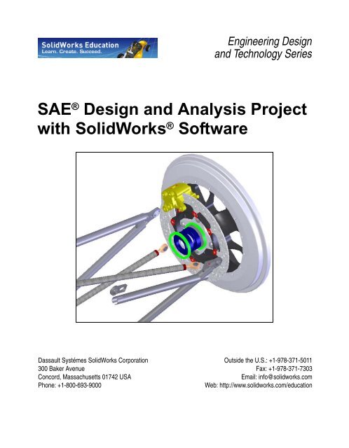
Engineering Design<br />
and Technology Series<br />
<strong>SAE</strong> ® Design and Analysis <strong>Project</strong><br />
with <strong>SolidWorks</strong> ® Software<br />
Dassault Systémes <strong>SolidWorks</strong> Corporation<br />
300 Baker Avenue<br />
Concord, Massachusetts 01742 USA<br />
Phone: +1-800-693-9000<br />
Put Picture Here<br />
Outside the U.S.: +1-978-371-5011<br />
Fax: +1-978-371-7303<br />
Email: info@solidworks.com<br />
Web: http://www.solidworks.com/education
© 1995-2010, Dassault Systèmes <strong>SolidWorks</strong><br />
Corporation, a Dassault Systèmes S.A. company,<br />
300 Baker Avenue, Concord, Mass. 01742 USA.<br />
All Rights Reserved.<br />
The information and the software discussed in this<br />
document are subject to change without notice and<br />
are not commitments by Dassault Systèmes<br />
<strong>SolidWorks</strong> Corporation (DS <strong>SolidWorks</strong>).<br />
No material may be reproduced or transmitted in any<br />
form or by any means, electronic or mechanical, for<br />
any purpose without the express written permission<br />
of DS <strong>SolidWorks</strong>.<br />
The software discussed in this document is furnished<br />
under a license and may be used or copied only in<br />
accordance with the terms of this license. All<br />
warranties given by DS <strong>SolidWorks</strong> as to the<br />
software and documentation are set forth in the<br />
<strong>SolidWorks</strong> Corporation License and Subscription<br />
Service Agreement, and nothing stated in, or implied<br />
by, this document or its contents shall be considered<br />
or deemed a modification or amendment of such<br />
warranties.<br />
Patent Notices for <strong>SolidWorks</strong> Standard,<br />
Premium, and Professional Products<br />
U.S. Patents 5,815,154; 6,219,049; 6,219,055;<br />
6,603,486; 6,611,725; 6,844,877; 6,898,560;<br />
6,906,712; 7,079,990; 7,184,044; 7,477,262;<br />
7,502,027; 7,558,705; 7,571,079; 7,643,027 and<br />
foreign patents, (e.g., EP 1,116,190 and JP<br />
3,517,643).<br />
U.S. and foreign patents pending.<br />
Trademarks and Other Notices for All<br />
<strong>SolidWorks</strong> Products<br />
<strong>SolidWorks</strong>, 3D PartStream.NET, 3D<br />
ContentCentral, PDMWorks, eDrawings, and the<br />
eDrawings logo are registered trademarks and<br />
FeatureManager is a jointly owned registered<br />
trademark of DS <strong>SolidWorks</strong>.<br />
<strong>SolidWorks</strong> Enterprise PDM, <strong>SolidWorks</strong><br />
Simulation, <strong>SolidWorks</strong> Flow Simulation, and<br />
<strong>SolidWorks</strong> 2010 are product names of DS<br />
<strong>SolidWorks</strong>.<br />
CircuitWorks, Feature Palette, FloXpress,<br />
PhotoWorks, TolAnalyst, and XchangeWorks are<br />
trademarks of DS <strong>SolidWorks</strong>.<br />
FeatureWorks is a registered trademark of<br />
Geometric Ltd.<br />
Other brand or product names are trademarks or<br />
registered trademarks of their respective holders.<br />
Document Number: PME1118-ENG<br />
COMMERCIAL COMPUTER<br />
SOFTWARE - PROPRIETARY<br />
U.S. Government Restricted Rights. Use,<br />
duplication, or disclosure by the government is<br />
subject to restrictions as set forth in FAR 52.227-19<br />
(Commercial Computer Software - Restricted<br />
Rights), DFARS 227.7202 (Commercial Computer<br />
Software and Commercial Computer Software<br />
Documentation), and in the license agreement, as<br />
applicable.<br />
Contractor/Manufacturer:<br />
Dassault Systèmes <strong>SolidWorks</strong> Corporation, 300<br />
Baker Avenue, Concord, Massachusetts 01742 USA<br />
Copyright Notices for <strong>SolidWorks</strong> Standard,<br />
Premium, and Professional Products<br />
Portions of this software © 1990-2010 Siemens<br />
Product Lifecycle Management Software III (GB)<br />
Ltd.<br />
Portions of this software © 1998-2010 Geometric<br />
Ltd.<br />
Portions of this software © 1986-2010 mental<br />
images GmbH & Co. KG.<br />
Portions of this software © 1996-2010 Microsoft<br />
Corporation. All rights reserved.<br />
Portions of this software © 2000-2010 Tech Soft 3D.<br />
Portions of this software © 1998-2010<br />
3Dconnexion.<br />
This software is based in part on the work of the<br />
Independent JPEG Group. All Rights Reserved.<br />
Portions of this software incorporate PhysX by<br />
NVIDIA 2006-2010.<br />
Portions of this software are copyrighted by and are<br />
the property of UGS Corp. © 2010.<br />
Portions of this software © 2001-2010 Luxology,<br />
Inc. All Rights Reserved, Patents Pending.<br />
Portions of this software © 2007-2010 DriveWorks<br />
Ltd.<br />
Copyright 1984-2010 Adobe Systems Inc. and its<br />
licensors. All rights reserved. Protected by U.S.<br />
Patents 5,929,866; 5,943,063; 6,289,364; 6,563,502;<br />
6,639,593; 6,754,382; Patents Pending.<br />
Adobe, the Adobe logo, Acrobat, the Adobe PDF<br />
logo, Distiller and Reader are registered trademarks<br />
or trademarks of Adobe Systems Inc. in the U.S. and<br />
other countries.<br />
For more copyright information, in <strong>SolidWorks</strong> see<br />
Help > About <strong>SolidWorks</strong>.<br />
Other portions of <strong>SolidWorks</strong> 2010 are licensed<br />
from DS <strong>SolidWorks</strong> licensors.<br />
Copyright Notices for <strong>SolidWorks</strong> Simulation<br />
Portions of this software © 2008 Solversoft<br />
Corporation.<br />
PCGLSS © 1992-2007 Computational Applications<br />
and System Integration, Inc. All rights reserved.<br />
Portions of this product are distributed under license<br />
from DC Micro Development, Copyright © 1994-<br />
2005 DC Micro Development, Inc. All rights reserve
<strong>SolidWorks</strong><br />
Engineering Design and Technology Series<br />
Table of Contents<br />
Lesson 1: Introduction .......................................................................................1<br />
Using This Book........................................................................................................... 2<br />
What is <strong>SolidWorks</strong> Software?..................................................................................... 2<br />
Prerequisites.................................................................................................................. 2<br />
Conventions Used in This Book................................................................................... 3<br />
Before You Begin......................................................................................................... 3<br />
Analyzing a Structure Using <strong>SolidWorks</strong> and <strong>SolidWorks</strong> Simulation ....................... 4<br />
Lesson 2: Using Assemblies .............................................................................5<br />
Creating Parts In-Context ............................................................................................ 6<br />
Opening an Assembly with Quick View................................................................ 6<br />
Hiding and Showing Components ......................................................................... 7<br />
The Assembly FeatureManager design tree ............................................................... 10<br />
Working In-Context.................................................................................................... 11<br />
Edit Assembly Mode vs. Edit Part Mode............................................................. 11<br />
In-Context Parts and Virtual Parts ....................................................................... 12<br />
Setup for Using Edit Part ..................................................................................... 12<br />
Creating a New Part ............................................................................................ 13<br />
Edit Part Mode............................................................................................................ 14<br />
Why do the Colors Change? ................................................................................ 14<br />
Controlling the Display........................................................................................ 14<br />
Understanding the Color Coding ......................................................................... 20<br />
Extrusions In-Context .......................................................................................... 24<br />
Edit Assembly Mode .................................................................................................. 26<br />
Working with Virtual Parts .................................................................................. 26<br />
Adding Component Instances and Mating ................................................................. 27<br />
In-Context Part Editing............................................................................................... 31<br />
Opening a Part from an Assembly ............................................................................. 32<br />
Multi-body Materials.................................................................................................. 33<br />
i
<strong>SolidWorks</strong><br />
Engineering Design and Technology Series<br />
Reordering Features ............................................................................................. 34<br />
Materials ..................................................................................................................... 35<br />
Pack and Go................................................................................................................ 37<br />
Work Flow ........................................................................................................... 37<br />
Lesson 3: Creating a Weldment ......................................................................40<br />
Creating Weldment Parts............................................................................................ 41<br />
Planes and Sketches ............................................................................................. 41<br />
Structural Members.............................................................................................. 41<br />
Weldments .................................................................................................................. 42<br />
Creating a Weldment............................................................................................ 42<br />
Using Different Planes and Sketches ................................................................... 45<br />
Using 2D Sketches ............................................................................................... 47<br />
Renaming and Opening a Virtual Part ................................................................. 51<br />
Additional Planes and 2D Sketches ..................................................................... 54<br />
Sketching with Pierce Relations........................................................................... 56<br />
Adding Bracing to the Frame ..................................................................................... 60<br />
Using 3D Sketches...................................................................................................... 61<br />
Sketching in the X, Y and Z Directions ............................................................... 61<br />
3D Sketch Dimensions......................................................................................... 62<br />
Placing a Component Using Sketch Geometry .......................................................... 64<br />
Making Changes................................................................................................... 66<br />
Working With Sub-Assemblies .................................................................................. 67<br />
Opening a Sub-assembly from the Assembly ...................................................... 67<br />
Rigid vs. Flexible Sub-Assemblies ...................................................................... 68<br />
Bracing Sketches ........................................................................................................ 70<br />
Remaining Sketches............................................................................................. 71<br />
Weldment Structural Members................................................................................... 73<br />
Creating Custom Profiles ..................................................................................... 74<br />
Adding Structural Members ....................................................................................... 77<br />
Corner Treatments................................................................................................ 78<br />
Using Trim/Extend ..................................................................................................... 82<br />
Trimming Boundary............................................................................................. 82<br />
Using Folders ....................................................................................................... 84<br />
Map for Structural Member Types and Trim/Extend .......................................... 85<br />
Mirroring Structural Members ............................................................................. 86<br />
Editing.........................................................................................................................87<br />
Editing the Corner Treatment............................................................................... 87<br />
Using Locate Profile ............................................................................................ 89<br />
Using Instant 3D .................................................................................................. 92<br />
Checking Clearances............................................................................................ 94<br />
Interference Detection.......................................................................................... 97<br />
ii
<strong>SolidWorks</strong><br />
Engineering Design and Technology Series<br />
Mounting Plates.......................................................................................................... 99<br />
Creating a Reusable Sketch.................................................................................. 99<br />
Pasting the Sketch .............................................................................................. 100<br />
Weldment Cut Lists .................................................................................................. 106<br />
Cut List Properties.............................................................................................. 107<br />
Save as External File.......................................................................................... 108<br />
Lesson 4: Using Molds and Surfaces ...........................................................109<br />
Molds and Surfaces................................................................................................... 110<br />
The runner part.............................................................................................. 111<br />
Features in the Part............................................................................................. 112<br />
Anatomy of a Loft.............................................................................................. 113<br />
Creating Mold Tooling ............................................................................................. 114<br />
Surface and Solid Bodies ................................................................................... 114<br />
Description of the Bodies................................................................................... 115<br />
Mold Tools......................................................................................................... 116<br />
Using Surfaces ................................................................................................... 121<br />
Making Use of Symmetry......................................................................................... 127<br />
Lesson 5: Brake Rotor Analysis....................................................................130<br />
Brake Rotor Design .................................................................................................. 131<br />
<strong>SolidWorks</strong> Simulation Interface....................................................................... 132<br />
Transient Thermal Analysis...................................................................................... 134<br />
Thermal Boundary Conditions ................................................................................. 135<br />
Convection ......................................................................................................... 135<br />
Heat Power......................................................................................................... 138<br />
Post Processing ......................................................................................................... 140<br />
Static Study............................................................................................................... 142<br />
Temperature Dependent Material Properties ..................................................... 143<br />
Fixtures ..................................................................................................................... 143<br />
Loading..................................................................................................................... 145<br />
Braking Force..................................................................................................... 146<br />
Thermal Loading................................................................................................ 147<br />
Post Processing ......................................................................................................... 148<br />
Editing Plots....................................................................................................... 149<br />
Chart Options ..................................................................................................... 149<br />
Settings............................................................................................................... 149<br />
Conclusions............................................................................................................... 151<br />
Lesson 6: Frame Analysis..............................................................................152<br />
Torsional Rigidity..................................................................................................... 153<br />
Element Types .......................................................................................................... 153<br />
iii
<strong>SolidWorks</strong><br />
Engineering Design and Technology Series<br />
Shell Elements.................................................................................................... 154<br />
Beam Elements................................................................................................... 154<br />
Preparing for Analysis .............................................................................................. 155<br />
Experimental Design ................................................................................................ 156<br />
Beam Meshing.......................................................................................................... 157<br />
Section Properties............................................................................................... 158<br />
End Conditions................................................................................................... 158<br />
Trusses................................................................................................................ 159<br />
Joint Group......................................................................................................... 160<br />
Merging Joints Automatically............................................................................ 161<br />
Fixtures ..................................................................................................................... 162<br />
Loading..................................................................................................................... 163<br />
Post Processing ......................................................................................................... 165<br />
Cylindrical Coordinates ..................................................................................... 166<br />
Torsional Rigidity .............................................................................................. 168<br />
Beam Stresses..................................................................................................... 169<br />
Cross Section Directions 1 and 2 ....................................................................... 170<br />
Shear and Bending Diagrams............................................................................. 171<br />
Conclusion ................................................................................................................ 173<br />
Lesson 7: Intake Analysis ..............................................................................174<br />
Intake Manifold Design ............................................................................................ 175<br />
Model Preparations................................................................................................... 175<br />
External Flow Analysis...................................................................................... 175<br />
Internal Flow Analysis ....................................................................................... 175<br />
<strong>SolidWorks</strong> Flow Simulation Interface.............................................................. 177<br />
Lids..................................................................................................................... 177<br />
Check Geometry................................................................................................. 179<br />
Creating the <strong>Project</strong> .................................................................................................. 179<br />
Engineering Goals.............................................................................................. 187<br />
Post-Processing......................................................................................................... 189<br />
View Settings ..................................................................................................... 190<br />
Discussion .......................................................................................................... 192<br />
Conclusions............................................................................................................... 192<br />
iv
<strong>SolidWorks</strong><br />
Engineering Design and Technology Series<br />
When you complete this lesson, you will be able to:<br />
Lesson 1<br />
Introduction<br />
Describe the relationship between Parts, Assemblies and Drawings;<br />
Identify the principal components of the <strong>SolidWorks</strong> user interface;<br />
Download and extract the required companion files.<br />
1
<strong>SolidWorks</strong> Introduction<br />
Engineering Design and Technology Series<br />
Using This Book<br />
The <strong>SAE</strong> Design and Analysis <strong>Project</strong> with <strong>SolidWorks</strong> Software<br />
helps you learn the principles of assembly design and structural analysis using<br />
<strong>SolidWorks</strong> and <strong>SolidWorks</strong> Simulation as an integral part of a creative and<br />
iterative design process.<br />
For this project, You will “learn by doing” as you complete modeling and<br />
structural analysis lessons.<br />
What is <strong>SolidWorks</strong> Software?<br />
<strong>SolidWorks</strong> is design automation software. In <strong>SolidWorks</strong>, you sketch ideas and<br />
experiment with different designs to create 3D models using the easy to learn<br />
Windows ® graphical user interface.<br />
<strong>SolidWorks</strong> is used by students, designers, engineers and other professionals to<br />
produce single and complex parts, assemblies and drawings.<br />
Prerequisites<br />
Before you begin the <strong>SAE</strong> Design and Analysis <strong>Project</strong> with<br />
<strong>SolidWorks</strong> Software you should complete the following online tutorials that<br />
are integrated in the <strong>SolidWorks</strong> software:<br />
Lesson 1 - Parts<br />
Lesson 2 - Assemblies<br />
Lesson 3 - Drawings<br />
You can access the online tutorials by clicking Help, <strong>SolidWorks</strong> Tutorials, All<br />
<strong>SolidWorks</strong> Tutorials (Set 1). The online tutorial resizes the <strong>SolidWorks</strong> window<br />
and runs beside it.<br />
As an alternative, you can complete the following lessons from An Introduction to<br />
Engineering Design With <strong>SolidWorks</strong>:<br />
Lesson 1: Using the Interface<br />
Lesson 2: Basic Functionality<br />
Lesson 3: The 40-Minute Running Start<br />
Lesson 4: Assembly Basics<br />
Lesson 6: Drawing Basics<br />
Using This Book 2
<strong>SolidWorks</strong> Introduction<br />
Engineering Design and Technology Series<br />
Conventions Used in This Book<br />
This manual uses the following typographical conventions:<br />
Convention Meaning<br />
Bold Sans Serif <strong>SolidWorks</strong> commands and options appear in this style.<br />
For example, Insert, Boss means choose the Boss option<br />
from the Insert menu.<br />
Typewriter Feature names and file names appear in this style. For<br />
example, Sketch1.<br />
17 Do this step. The steps in the lessons are numbered in sans serif bold.<br />
Before You Begin<br />
If you have not done so already, copy the companion files for the lessons onto<br />
your computer before you begin this project.<br />
1 Start <strong>SolidWorks</strong>.<br />
Using the Start menu, start the <strong>SolidWorks</strong> application.<br />
2 <strong>SolidWorks</strong> Content.<br />
Click Design Library to open the design library<br />
task pane.<br />
Click on <strong>SolidWorks</strong> Content to show the<br />
folders below it.<br />
Click on <strong>SolidWorks</strong> Educator Curriculum.<br />
Click <strong>SAE</strong> <strong>Project</strong> Files - English.<br />
Note: There may be more curriculum folders listed in<br />
addition to the <strong>SAE</strong> <strong>Project</strong> Files.<br />
The lower pane will display an icon representing a<br />
Zip file that contains the companion files for this<br />
project.<br />
Conventions Used in This Book 3
<strong>SolidWorks</strong> Introduction<br />
Engineering Design and Technology Series<br />
3 Download the Zip file.<br />
Press Ctrl and click the icon.<br />
You will be prompted for a folder in<br />
which to save the Zip file.<br />
Ask your teacher where you should<br />
save the Zip file. Usually the<br />
C:\Temp folder is a good location.<br />
Click OK.<br />
Tip: Remember where you saved it.<br />
4 Open the Zip file.<br />
Browse to the folder where you saved the Zip file in step 3.<br />
Double-click the <strong>SAE</strong> <strong>Project</strong> Files.zip file.<br />
5 Click Extract.<br />
Click Extract and Browse to the location where you want to save the<br />
files. The system will automatically create a folder named<br />
_<strong>SAE</strong>_<strong>Project</strong>_ENG in the location you specify. For example, you might want<br />
to save it in My Documents. Check with your teacher about where to save the<br />
files.<br />
You now have a folder named <strong>SAE</strong> <strong>Project</strong> Files on your disk. The data in this<br />
folder will be used in the exercises.<br />
Tip: Remember where you saved it.<br />
Analyzing a Structure Using <strong>SolidWorks</strong> and <strong>SolidWorks</strong> Simulation<br />
During this session, you will learn how to analyze a structure using <strong>SolidWorks</strong><br />
and <strong>SolidWorks</strong> Simulation.<br />
Once you have had a chance to see how easy it is to use <strong>SolidWorks</strong> solid<br />
modeling software, you will use an assembly to check whether components fit<br />
properly.<br />
You will then make a drawing of one of the components, complete with a cut list.<br />
If a printer is available, you can print out a hardcopy of your drawing.<br />
Analyzing a Structure Using <strong>SolidWorks</strong> and <strong>SolidWorks</strong> Simulation 4
<strong>SolidWorks</strong><br />
Engineering Design and Technology Series<br />
When you complete this lesson, you will be able to:<br />
Lesson 2<br />
Using Assemblies<br />
Understand the difference between edit assembly and edit part modes;<br />
Create a virtual, in-context part;<br />
Open a part from the assembly;<br />
Create a new instance from an existing instance;<br />
Set the materials in a part;<br />
Use pack and go to manage the files.<br />
5
<strong>SolidWorks</strong> Using Assemblies<br />
Engineering Design and Technology Series<br />
Creating Parts In-Context<br />
A thorough knowledge of how to<br />
work with assemblies is critical to<br />
success with <strong>SolidWorks</strong>.<br />
In this example, you will create a<br />
virtual part and use in-context<br />
techniques to mode a brake pad using<br />
geometry from both the Rotor -<br />
Cast Iron and Brake Caliper<br />
components.<br />
The component will copied to create<br />
a second instance and it will be mated<br />
into the assembly.<br />
Opening an Assembly with Quick View<br />
Clicking the Quick view / Selective open when you open an assembly allows<br />
you to view only the components that you want to view.<br />
1 Open Brake&Wheel.<br />
Click File, Open and select the assembly Brake&Wheel. Click Quick view /<br />
Selective open and click Open.<br />
6
<strong>SolidWorks</strong> Using Assemblies<br />
Engineering Design and Technology Series<br />
Hiding and Showing Components<br />
Components can be hidden or shown at any time to create an uncluttered display<br />
and make working on the assembly faster.<br />
In addition, components that are hidden before opening the assembly are not<br />
loaded into memory, further decreasing the load on the machine.<br />
Tip: The Quick view / Selective open settings are stored in a Display State.<br />
There are many ways to hide and show components. Here are a few useful<br />
methods and where they are best used.<br />
Many<br />
Components<br />
Single or<br />
Few<br />
Components<br />
Hiding Components Showing Components<br />
Hide Others- Hides all<br />
visible components but the<br />
selected component(s).<br />
Hide/Show Components-<br />
Hides the selected visible<br />
components.<br />
2 Orientation.<br />
The assembly open in an Isometric orientation. Click in the graphics area and<br />
press Shift+Arrow Up to change the view orientation.<br />
3 Hide others.<br />
Right-click the Rotor - Cast Iron and select Hide Others.<br />
Show Hidden Components-<br />
Shows all the hidden<br />
components for selection.<br />
Hide/Show Components-<br />
Shows the selected hidden<br />
components.<br />
7
<strong>SolidWorks</strong> Using Assemblies<br />
Engineering Design and Technology Series<br />
4 Show hidden.<br />
Right-click in the graphics area and select Show Hidden<br />
Components. Click the Brake Caliper component as shown.<br />
Click Exit Show-Hidden to complete the command.<br />
5 Selective open.<br />
Click All components displayed and click<br />
Open. These are the only components that we<br />
need to view right now.<br />
6 Message.<br />
A message appears.<br />
Because you used “Selective Open”, hidden components are not<br />
loaded into memory. Therefore, when you first show a hidden<br />
component you might notice a delay while it is loaded. Also, a<br />
new Display State is created corresponding to the “Selective<br />
Open” state. Click OK.<br />
7 Display state.<br />
The new Display State is stored under the current<br />
configuration Default and is named New Display<br />
State-1.<br />
The original Display State Default_Display State-1<br />
retains the settings of all components visible.<br />
8
<strong>SolidWorks</strong> Using Assemblies<br />
Engineering Design and Technology Series<br />
8 Save.<br />
Click File, Save to save the assembly and parts.<br />
9 Orientation changes.<br />
Press the Spacebar and double-click the orientation *Isometric<br />
from the dialog. Middle (wheel)+click and drag the edge of the<br />
Rotor - Cast Iron as shown to rotate the geometry.<br />
10 Zoom.<br />
Click the Brake Caliper<br />
component in the FeatureManager<br />
design tree and click Zoom to<br />
Selection .<br />
9
<strong>SolidWorks</strong> Using Assemblies<br />
Engineering Design and Technology Series<br />
The Assembly FeatureManager design tree<br />
The assembly is comprised of components and mates. The components can be<br />
either part components or assembly components (sub-assemblies). The assembly<br />
FeatureManager design tree shows an accurate snapshot of the assembly using<br />
icons and text to describe the current settings.<br />
Sub-assembly<br />
Component<br />
Mates<br />
Folder<br />
11 AssemblyXpert.<br />
Click Tools, AssemblyXpert. The dialog lists the number of parts, unique parts,<br />
sub-assemblies and unique sub-assemblies among other things.<br />
Click OK.<br />
Hidden<br />
Part<br />
Component<br />
Hidden Sub-assembly<br />
Component<br />
Part Component<br />
Component<br />
Instance<br />
Mate<br />
10
<strong>SolidWorks</strong> Using Assemblies<br />
Engineering Design and Technology Series<br />
Working In-Context<br />
Working in-context means editing a component (part or assembly) while in the<br />
context of the assembly. The mode is toggled between Edit Assembly and Edit<br />
Part.<br />
Edit Assembly Mode vs. Edit Part Mode<br />
When an assembly is opened, it opens in the default Edit Assembly mode. To<br />
create or edit a component part in-context, Edit Part is used. You can toggle back<br />
and forth between the modes using Edit Component .<br />
Edit Assembly Edit Part<br />
Tip: Colors are used to indicate which mode is currently active. See “Why do the<br />
Colors Change?” on page 14 for more information.<br />
Below is a breakdown of some common actions that are typically performed in<br />
each mode:<br />
Edit Assembly Mode Edit Part Mode<br />
Adding new components Creating new sketches<br />
Inserting mates Creating sketch geometry<br />
Moving components Creating bosses or cut features<br />
11
<strong>SolidWorks</strong> Using Assemblies<br />
Engineering Design and Technology Series<br />
In-Context Parts and Virtual Parts<br />
In-Context Parts are parts that are created or edited<br />
in the context of the assembly. In-context part names<br />
appear in the FeatureManager design tree appended<br />
with an arrow (In-Context->).<br />
Virtual Parts are in-context parts that are saved<br />
within the assembly rather than as separate part files.<br />
Parts can be both in-context and virtual. Virtual part<br />
names appear in the FeatureManager design tree in<br />
square brackets [Virtual_Part^Test].<br />
Why use In-Context and Virtual Parts?<br />
In-Context parts reference other parts in the assembly and change automatically<br />
when the references change.<br />
Virtual Parts are more flexible because they can be renamed, deleted or saved as<br />
external (part) files at any time.<br />
Tip: If there are no references, do not create the part in-context.<br />
Setup for Using Edit Part<br />
There are settings under system options that can be used to determine how<br />
assemblies and virtual parts behave in Edit Part mode.<br />
12 Virtual part setting.<br />
Click Tools, Options, System Options, Assemblies and clear Save new<br />
components to external files.<br />
Do not click OK yet.<br />
13 In-context appearance setting.<br />
Click Tools, Options, System Options, Display/Selection and select Opaque<br />
Assembly from the pulldown menu under Assembly transparency for in<br />
context edit.<br />
Do not click OK yet.<br />
14 In-context part setting.<br />
Click Tools, Options, System Options, Colors and click Use specified color<br />
when editing parts in assemblies. That color is listed under the Assembly, Edit<br />
Part setting.<br />
Click OK.<br />
12
<strong>SolidWorks</strong> Using Assemblies<br />
Engineering Design and Technology Series<br />
Creating a New Part<br />
Creating a in-context new part<br />
requires a few selections including a<br />
planar face or plane for use as a<br />
sketch plane.<br />
The selected face or plane will<br />
establish the orientation and position<br />
of the Front plane of the new virtual<br />
part. This in turn defines the<br />
orientations of the Top and Right<br />
planes.<br />
15 New part.<br />
Click Insert, Component, New Part and select the face of the Brake<br />
Caliper as shown.<br />
13
<strong>SolidWorks</strong> Using Assemblies<br />
Engineering Design and Technology Series<br />
Edit Part Mode<br />
Edit Part Mode is the opposite toggle of Edit Assembly Mode and allows the use<br />
of sketch and feature tools within the assembly. It is triggered by adding a new<br />
part component or editing an existing part in the assembly.<br />
Why do the Colors Change?<br />
Due to the settings made (“Setup for Using Edit Part” on page 12), the appearance<br />
of all the parts remains opaque. The part being edited will appear in the<br />
Assembly, Edit Part color and all others appear in the Assembly, Non-Edit<br />
Parts color.<br />
Controlling the Display<br />
The display includes the visibility and colors of the components in the assembly.<br />
Controlling the display is the first step in managing the assembly itself, and the<br />
Display Pane is one of the best tools.<br />
Display Pane<br />
The Display Pane is a portion of the FeatureManager design tree<br />
that has visual controls and is usually hidden. The columns show the<br />
current state of Hide/Show, Display Mode, Appearance and<br />
Transparency and allow you to change them. The options are<br />
described below.<br />
Hide/Show - Toggles between Hide Component and Show<br />
Component.<br />
Display Mode - Sets the display to Wireframe, Hidden Lines<br />
Visible, Hidden Lines Removed, Shaded With Edges,<br />
Shaded, or Default Display.<br />
Appearance - Sets the appearance of the component. The lower triangle<br />
represents the part appearance while the upper triangle represents the<br />
component (assembly level) appearance.<br />
Transparency - Toggles Transparency on and off.<br />
Note: The display pane works independently of the mode.<br />
Hide/Show<br />
Display Mode<br />
Appearances<br />
Transparency<br />
14
<strong>SolidWorks</strong> Using Assemblies<br />
Engineering Design and Technology Series<br />
16 Display plane.<br />
Click Show Display Pane to expand the<br />
display plane and change the appearance of<br />
components.<br />
Expand the Brake Rotor Assembly folder.<br />
Click the Rotor - Cast Iron component in the<br />
Hide/Show column as shown to hide it.<br />
Click Hide Display Pane to close the display pane.<br />
15
<strong>SolidWorks</strong> Using Assemblies<br />
Engineering Design and Technology Series<br />
17 Convert entities.<br />
Click Convert Entities and select the face and click<br />
twice.<br />
Tip: If you see small green icons on the geometry of the sketch, you are seeing sketch<br />
relations. Click View, Sketch Relations to shut off their display.<br />
18 Delete.<br />
Delete three entities to open the end<br />
of the sketch.<br />
Note: There is one large arc and two small ones connected to it. Only one small arc is<br />
shown here.<br />
16
<strong>SolidWorks</strong> Using Assemblies<br />
Engineering Design and Technology Series<br />
19 Convert edge.<br />
Click Show Display Pane and show the Rotor - Cast Iron component.<br />
Click Convert Entities and select the edge of the Rotor - Cast Iron<br />
component. Click twice.<br />
20 Sketch fillets.<br />
Click Tools, Sketch Tools, Fillet , set the Fillet Radius<br />
to 2.5mm, and select the first set of geometry by selecting<br />
the geometry inside of where they would intersect.<br />
Repeat the selections for the similar geometry on the opposite side. Click<br />
twice.<br />
17
<strong>SolidWorks</strong> Using Assemblies<br />
Engineering Design and Technology Series<br />
21 View normal to.<br />
Click View Normal To and<br />
zoom in as shown.<br />
22 Delete.<br />
Box select from upper left to lower<br />
right as shown to select the three<br />
entities.<br />
Delete the three selected entities.<br />
23 Drag endpoints.<br />
Drag the endpoint of the vertical line<br />
outside the geometry as shown.<br />
Repeat for the other vertical line and<br />
stop where the endpoints are<br />
horizontal.<br />
18
<strong>SolidWorks</strong> Using Assemblies<br />
Engineering Design and Technology Series<br />
24 Tangent Arc.<br />
Click Tools, Sketch Entities,<br />
Tangent Arc and create the arc<br />
between the two endpoints as<br />
shown.<br />
25 Drag and drop.<br />
Drag the centerpoint of the arc to the<br />
edge of the circular edge. Drop it on<br />
the centerpoint that appears.<br />
26 Previous view.<br />
Click Previous View to go back to previous views and zoom states. Return to<br />
the zoomed isometric view.<br />
19
<strong>SolidWorks</strong> Using Assemblies<br />
Engineering Design and Technology Series<br />
27 Extrude.<br />
Click Extrude and set the Depth to 3mm. Click .<br />
Understanding the Color Coding<br />
The part turns blue when the extrusion is completed. The reason was explained<br />
earlier (“Why do the Colors Change?” on page 14) but until there is a solid body,<br />
it is difficult to notice. This is the Assembly, Edit Part color and it appears in<br />
both the graphics and in the FeatureManager design tree.<br />
20
<strong>SolidWorks</strong> Using Assemblies<br />
Engineering Design and Technology Series<br />
28 New sketch.<br />
Select the face and click Sketch .<br />
29 Convert entities.<br />
Click Convert Entities and select<br />
the edge as shown. Click .<br />
21
<strong>SolidWorks</strong> Using Assemblies<br />
Engineering Design and Technology Series<br />
30 Offset entities.<br />
Hide the Rotor - Cast Iron component. Click Offset<br />
Entities and set the Offset Distance to 2mm. Select the<br />
edge, click Reverse and click .<br />
Repeat the procedure for the opposite side.<br />
31 Convert.<br />
Show the Rotor - Cast Iron<br />
component. Select the edge as shown<br />
and click Convert Entities . Click<br />
.<br />
22
<strong>SolidWorks</strong> Using Assemblies<br />
Engineering Design and Technology Series<br />
32 Drag.<br />
Drag the open endpoints out beyond<br />
the converted edge.<br />
33 Trim.<br />
Click Trim Entities , Power trim<br />
. Click+Drag across the sections<br />
of geometry using the paths shown to<br />
trim away excess geometry.<br />
23
<strong>SolidWorks</strong> Using Assemblies<br />
Engineering Design and Technology Series<br />
34 Sketch fillets.<br />
Add sketch fillets Radius 1mm as<br />
shown.<br />
Tip: If corners are trimmed to a single<br />
endpoint, select the endpoint to add<br />
the fillet.<br />
Extrusions In-Context<br />
Extrusions can also be created in-context when external<br />
generator is referenced. In this example, the depth of an<br />
extrusion is measured as an offset from an existing face.<br />
35 Extrude.<br />
Click Extrude and set the End Condition to Offset<br />
from Surface. Set the Offset Distance to 1.5mm. Click in<br />
Face/Plane field.<br />
24
<strong>SolidWorks</strong> Using Assemblies<br />
Engineering Design and Technology Series<br />
36 Select other.<br />
Right-click the face as shown and select Select Other. Click the top selection,<br />
Face@[Brake Rotor Assembly/Rotor - Cast Iron].<br />
Tip: The top selection at the cursor is not listed. Why? It is assumed that if you wanted<br />
to select that face you would have selected it directly.<br />
37 Offset distance.<br />
Check the direction and click .<br />
25
<strong>SolidWorks</strong> Using Assemblies<br />
Engineering Design and Technology Series<br />
Edit Assembly Mode<br />
Edit Assembly Mode is the opposite toggle of Edit Part Mode and is the default<br />
state of the assembly where you can add components and mates. It is triggered by<br />
exiting the editing of a part in the assembly or opening of an assembly file.<br />
1 Edit assembly.<br />
Click Edit Component or the confirmation corner to edit the assembly.<br />
This returns you to edit assembly mode and all the colors return to their original<br />
settings.<br />
Working with Virtual Parts<br />
The virtual part has been stored inside the assembly since it was created. Now that<br />
it nearly complete, we will save it externally and make it a real part.<br />
Renaming a Virtual Part<br />
2 Rename.<br />
Right-click the [Part1^Brake&Wheel] component and select Rename Part.<br />
Type the name Brake Pad.<br />
Tip: Although the part has been renamed, it remains a virtual part.<br />
26
<strong>SolidWorks</strong> Using Assemblies<br />
Engineering Design and Technology Series<br />
Saving a Virtual Part as an External Part<br />
The virtual part requires a location on disk to store the new *.sldprt file.<br />
3 Save as external file.<br />
Right-click the part and select<br />
Save Part (in External File). The<br />
file Brake Pad.sldprt is added<br />
to the assembly folder.<br />
Click Same As Assembly and<br />
OK.<br />
Tip: The part name appears without the square brackets.<br />
Adding Component Instances and Mating<br />
Components can be added to the assembly in several ways. If there is already an<br />
instance of that component in the assembly, additional instances can be added<br />
using control+drag and drop.<br />
4 Copy an instance.<br />
Click and Control+drag the Brake Pad component. Drop the component<br />
outside the Brake Caliper as shown.<br />
Adding Component Instances and Mating 27
<strong>SolidWorks</strong> Using Assemblies<br />
Engineering Design and Technology Series<br />
5 Hide component.<br />
Click the Rotor - Cast Iron component and click Hide Components .<br />
6 First mate.<br />
Press Shift+Up Arrow key. Click Insert, Mate and select the faces as shown.<br />
Click Coincident and Anti-Aligned . Click .<br />
Adding Component Instances and Mating 28
<strong>SolidWorks</strong> Using Assemblies<br />
Engineering Design and Technology Series<br />
7 Second mate.<br />
Press the Down Arrow key. Select the faces as shown, click Coincident and<br />
click .<br />
8 Third mate.<br />
Hide the Brake Caliper<br />
component. Select the faces as<br />
shown, click Coincident and click<br />
.<br />
Show the Brake Caliper component.<br />
Adding Component Instances and Mating 29
<strong>SolidWorks</strong> Using Assemblies<br />
Engineering Design and Technology Series<br />
Viewing the Mates of a Component<br />
The mates used to constrain a component can be listed and viewed using View<br />
Mates. It is a useful tool in understanding how components are used in the<br />
assembly.<br />
Note: The arrow symbol indicates a path to ground. Mates marked like this are the<br />
ones that hold the component in place.<br />
9 View mates.<br />
Click the Brake Pad and View Mates .<br />
Adding Component Instances and Mating 30
<strong>SolidWorks</strong> Using Assemblies<br />
Engineering Design and Technology Series<br />
In-Context Part Editing<br />
Any component part can be edited in the assembly whether it was created in the<br />
context of the assembly or not. Toggling back to edit part mode uses the same<br />
command; Edit Part.<br />
10 Edit part.<br />
Click Brake Pad and Edit Part .<br />
11 New sketch.<br />
Click the face and click Insert Sketch . A new sketch has been created on the<br />
face.<br />
12 Convert edge.<br />
Click Convert Entities . Click the circular edge as<br />
shown. Click .<br />
Exit the sketch.<br />
Adding Component Instances and Mating 31
<strong>SolidWorks</strong> Using Assemblies<br />
Engineering Design and Technology Series<br />
Opening a Part from an Assembly<br />
In this example, we will create a slot is to match up with the<br />
hole in the Brake Pad component. The slot will be<br />
constructed from an existing hole and makes for easier fit<br />
up.<br />
1 Open Brake Pad.<br />
Click on the Brake Pad in the FeatureManager design tree and select Open<br />
.<br />
2 Edit a sketch.<br />
Right-click on Sketch3-> in the FeatureManager<br />
design tree and select Edit Sketch .<br />
3 Construction.<br />
Click the circle and click for construction to make it dashed.<br />
4 Slot.<br />
Click Tools, Sketch Entities, Centerpoint Straight Slot and place the<br />
cursor at the center of the circle. Drag the cursor horizontally and click to create<br />
the centerline. Drag vertically and click to create the height. Click .<br />
Adding Component Instances and Mating 32
<strong>SolidWorks</strong> Using Assemblies<br />
Engineering Design and Technology Series<br />
5 Relations.<br />
Click the circle and a horizontal line<br />
of the slot. Add a Tangent<br />
relation.<br />
6 Dimension and cut.<br />
Add a dimension as shown to fully define the sketch.<br />
Create a cut using a Through All end condition.<br />
Multi-body Materials<br />
In order to have different materials in the same part there must be multiple solid<br />
bodies (multi-bodies) within that part.<br />
This part is currently made up of three features; two bosses and one cut feature.<br />
They are listed in their order of creation. There is just one solid body because by<br />
default new boss features are merged to the current body. The part will be edited<br />
to create multi-bodies.<br />
Boss-Extrude1-> Boss-Extrude2-> Cut-Extrude1-><br />
Multi-body Materials 33
<strong>SolidWorks</strong> Using Assemblies<br />
Engineering Design and Technology Series<br />
Reordering Features<br />
Features can be reordered in the Feature Manager design tree using drag and drop.<br />
The rule to remember is that you cannot reorder a child feature before the parent<br />
feature. So how can you determine the parent/child relationships?<br />
Parent/Child Relationships<br />
The Parent/Child tool is used to determine the parents and children of any<br />
feature. In this case it will be used to determine the limits of where a feature can<br />
be reordered.<br />
7 Parent/child.<br />
Right-click the Cut-Extrude1 feature<br />
and select Parent/Child. The dialog tells<br />
you that the Boss-Extrude1 and<br />
Sketch4 features are the parents of the<br />
selected feature. This also means that the<br />
Boss-Extrude2 feature is not. This<br />
means that the child can be moved to a<br />
position between the boss features. Click Close.<br />
Note: The Sketch4 feature is embedded in the Cut-Extrude1 feature.<br />
8 Reorder.<br />
Drag the Cut-Extrude1 feature and drop it on the Boss-Extrude1 feature.<br />
This places it between the boss features.<br />
9 Folder.<br />
Right-click the first feature Boss-Extrude1,<br />
Control+click the second feature Cut-Extrude1 and<br />
select Add to New Folder. Name the folder Backing.<br />
Multi-body Materials 34
<strong>SolidWorks</strong> Using Assemblies<br />
Engineering Design and Technology Series<br />
10 Edit feature.<br />
Click Boss-Extrude2 and Edit Feature . Clear Merge result and click .<br />
There are now two solid bodies named Cut-Extrude1 and Boss-Extrude2.<br />
Rename them to Plate and Pad as shown.<br />
Tip: The default names were taken from the last feature that was applied to the body.<br />
Materials<br />
Materials can be added to the entire part or to selected solid bodies within the part.<br />
In this case we will take advantage of the multi-body format to assign different<br />
materials to each body.<br />
11 Material for the Plate.<br />
Right-click the body Plate and select Material, Edit<br />
Material. Under Steel, select 1023 Carbon Steel Sheet<br />
(SS). Click Apply and Close.<br />
12 Material for the pad body.<br />
Right-click the body Boss-Extrude2 and select<br />
Material. Under Other Non-metals, select Ceramic<br />
Porelain. Click Apply and Close.<br />
Note: Custom materials and custom material libraries can be<br />
created.<br />
Materials 35
<strong>SolidWorks</strong> Using Assemblies<br />
Engineering Design and Technology Series<br />
13 Open assembly.<br />
Press Control+Tab and move the cursor to the assembly.<br />
This message appears:<br />
Models contained within the assembly have changed. Would you<br />
like to rebuild the assembly now? Click Yes.<br />
14 Edit assembly.<br />
Click Edit Component . Hide the Brake Caliper<br />
and Rotor - Cast Iron components.<br />
15 Display state.<br />
Select the original Display State Default_Display State-1 to have all the<br />
components visible.<br />
Materials 36
<strong>SolidWorks</strong> Using Assemblies<br />
Engineering Design and Technology Series<br />
Pack and Go<br />
Pack and Go is utility that can be used to copy all files used by the assembly into<br />
a new folder or zip file, consolidating the file set into one location.<br />
New<br />
Folder<br />
Zip<br />
File<br />
Work Flow<br />
The work flow using Pack and Go creates multiple backups, using the last backup<br />
to start the next work session.<br />
Creating a Zip File<br />
Creating a zip file is a good way to consolidate the files and generate a backup in<br />
one step. The zip file can be used to start the next session and then be stored away.<br />
Materials 37
<strong>SolidWorks</strong> Using Assemblies<br />
Engineering Design and Technology Series<br />
1 Pack and go.<br />
Click File, Pack and Go and click Save to Zip file. Using Browse, set the<br />
location to a temporary folder, name the file Backup_1.zip and click Save.<br />
2 Unzip.<br />
At the start of the next session, unzip the file to a new folder and begin working.<br />
More files may be added from external drives or different folders.<br />
3 Repeat the process.<br />
At the start of the next session, unzip to a new folder and begin working. Repeat<br />
the process each time to keep all the files together.<br />
Adding to File Names<br />
If you want to rename the files with each new backup, the Add prefix and Add<br />
suffix options can be used.<br />
For example, the file name Brake Caliper could become Brake Caliper_2<br />
or 2-Hub Assembly with a suffix or prefix added.<br />
Note: Using a prefix or suffix changes the name. It is not the same as using the<br />
<strong>SolidWorks</strong> Data Management product.<br />
Materials 38
<strong>SolidWorks</strong> Using Assemblies<br />
Engineering Design and Technology Series<br />
4 Appending the names.<br />
Use the same settings as in the previous step 1 but click Add suffix and type _1<br />
in the box. Click Save.<br />
Tip: Virtual parts that have not been saved as external files will appear greyed in the<br />
list with as the folder. They are stored within the<br />
assembly that was active when they were created.<br />
5 Save and close all files.<br />
Materials 39
<strong>SolidWorks</strong><br />
Engineering Design and Technology Series<br />
When you complete this lesson, you will be able to:<br />
Creating weldment parts;<br />
Using 3D sketches;<br />
Working with sub-assemblies;<br />
Creating custom profiles;<br />
Adding structural members;<br />
Trimming structural members;<br />
Editing structural members.<br />
Lesson 3<br />
Creating a Weldment<br />
40
<strong>SolidWorks</strong> Creating a Weldment<br />
Engineering Design and Technology Series<br />
Creating Weldment Parts<br />
The Frame will be built as a in-context Weldment using references from<br />
existing assemblies. The weldment process includes creating sketches, adding<br />
structural members and trimming the structural members.<br />
Planes and Sketches<br />
Planes and sketches, both 2D and 3D, are<br />
used to define the locations of the<br />
structural members in the weldment.<br />
Structural Members<br />
The structural members, square and<br />
round tubes in this example, are added to<br />
the lines and arcs of the sketches. After<br />
they are added they are trimmed to fit.<br />
41
<strong>SolidWorks</strong> Creating a Weldment<br />
Engineering Design and Technology Series<br />
Weldments<br />
A Weldment is a multi-body part composed of structural members. The<br />
centerlines of the structural members are sketched and profiles are selected from a<br />
library and are applied to the sketches.<br />
Tip: Most of the work to create a weldment is invested in the creation of the weldment<br />
sketches.<br />
Creating a Weldment<br />
Creating a typical weldment involves several<br />
steps to create and trim the weldment<br />
members.<br />
For example, this weldment is made up of<br />
five structural members; two of the longer<br />
length and three of the shorter length.<br />
The following chart defines the basic steps in<br />
creating a weldment part.<br />
Sketch<br />
Create<br />
Structural<br />
Members<br />
Trim and<br />
Extend<br />
Structural<br />
Members<br />
Create a new sketch that<br />
defines the centerlines of<br />
the weldment profiles.<br />
The sketch can be a 2D or<br />
3D sketch.<br />
Close the sketch.<br />
Click Structural<br />
Member and select<br />
geometry.<br />
Select a profile from the<br />
library for use with the<br />
geometry. [<br />
Click Trim/Extend<br />
and trim or extend the<br />
length of structural<br />
members to planes or<br />
other structural members.<br />
42
<strong>SolidWorks</strong> Creating a Weldment<br />
Engineering Design and Technology Series<br />
Some Important Points about Weldments<br />
Here are some important points to remember about weldments:<br />
Weldment parts are multi-body parts. Each structural member is an individual<br />
solid body.<br />
The profiles used are selected from a library. You must create your own<br />
profiles and library folders if the standard profiles are not what you need.<br />
Weldments can make use of symmetry. Structural members can be patterned<br />
using Mirror with the Bodies to Pattern option.<br />
A Cut-List folder is created to store information about the structural<br />
members and their lengths of the structural members. They can also be sorted<br />
by equal lengths.<br />
A Weldment Cut List table can be generated in a drawing of the weldment.<br />
The drawing can also have balloons like a BOM.<br />
Some Details About Weldment Sketches<br />
Weldment sketches are used to define the centerlines of beams used in the<br />
weldment. Continuous beams should be created using single pieces of geometry.<br />
If they are not, smaller separate pieces will be created.<br />
Sketches used for weldments may be different than sketches used for other<br />
features. For example, the sketch shown here would not be useful for a boss<br />
extrude or revolve.<br />
Single Line Multiple Lines<br />
43
<strong>SolidWorks</strong> Creating a Weldment<br />
Engineering Design and Technology Series<br />
1 Open Frame&Suspension.<br />
Click File, Open and select the assembly Frame&Suspension.<br />
2 Show sketches.<br />
Open any instance of the A-Arm Spherical Ball<br />
component.<br />
Right-click Sketch1 and select Show.<br />
Return to the assembly.<br />
Note: The A-Arm Spherical Ball components can be rotated for a better view of the<br />
sketch.<br />
44
<strong>SolidWorks</strong> Creating a Weldment<br />
Engineering Design and Technology Series<br />
Using Different Planes and Sketches<br />
In the process of adding a new part in-context, planar face or plane must be<br />
selected. This plane is used as a sketch plane and a new sketch is opened. In fact,<br />
several things happen at once when the plane is selected:<br />
A new in-context part is created.<br />
The new part is being edited.<br />
A new sketch is created on the selected plane.<br />
The new sketch is open.<br />
The selected plane becomes the Front plane of the new part.<br />
The new sketch may not be sketch you want. Although it is a requirement to select<br />
something, you do not have to use the sketch. You can just exit the sketch and<br />
create the plane or sketch that you need.<br />
3 New part.<br />
Click Insert, Component, New Part and select the plane Ground. A new<br />
sketch, in the new part, is automatically started on the selected plane. See<br />
“Creating a New Part” on page 13 for more information.<br />
Note: The Ground plane is selected, but in theory any plane or planar face could have<br />
been selected because none of the existing planes or planar faces is sufficient.<br />
4 Exit sketch.<br />
Right-click in the graphics area and select Exit Sketch to leave the current<br />
sketch. You are still editing the new part.<br />
45
<strong>SolidWorks</strong> Creating a Weldment<br />
Engineering Design and Technology Series<br />
5 Reference plane.<br />
Click Insert, Reference Geometry, Plane .<br />
Select the plane Front plane from the active part<br />
[Part1^Frame&Suspension] and Parallel.<br />
Select the centerpoint of an arc from a A-Arm Spherical<br />
Ball component of the A-arm - Upper assembly as<br />
shown. Click and rename the plane Upper_Arm.<br />
6 Lower plane.<br />
Using the same procedure as the previous step, create a<br />
new plane using the plane Front and a centerpoint of<br />
an arc from a A-Arm Spherical Ball component of<br />
the A-arm - Lower assembly. Click and rename<br />
the plane Lower_Arm.<br />
46
<strong>SolidWorks</strong> Creating a Weldment<br />
Engineering Design and Technology Series<br />
Using 2D Sketches<br />
A series of 2D sketches will be created to form the<br />
basic shape of the frame.<br />
3D sketches will be used to fill in much of the<br />
bracing and support structure after the basic shapes<br />
are complete.<br />
Note: Many of the 2D sketches, like this one, will require the creation of new planes.<br />
7 New sketch.<br />
Right-click the plane Lower_Arm and Sketch .<br />
8 Rectangle.<br />
Click Rectangle and sketch as shown.<br />
47
<strong>SolidWorks</strong> Creating a Weldment<br />
Engineering Design and Technology Series<br />
9 Reference to existing geometry.<br />
Add dimensions between the centerpoint of the arc and the edge of the rectangle<br />
as shown. Set the values to 35mm and 30mm. Selection of A-Arm Spherical<br />
Ball geometry for the dimensions creates external references to that component.<br />
10 Centering geometry.<br />
Sketch a centerline connecting the midpoint of the line and the origin as shown.<br />
Add a Horizontal relation.<br />
48
<strong>SolidWorks</strong> Creating a Weldment<br />
Engineering Design and Technology Series<br />
11 Added line and dimension.<br />
Add the line and dimensions 710mm and 430mm as shown.<br />
12 Exit sketch.<br />
Right-click in the graphics area and select Exit Sketch to leave the current<br />
sketch. Rename the sketch Main.<br />
13 New plane.<br />
Control+drag the plane Lower_Arm downwards. In the Plane dialog set the<br />
offset to 115mm. Rename the plane Lower_Frame.<br />
49
<strong>SolidWorks</strong> Creating a Weldment<br />
Engineering Design and Technology Series<br />
14 Hide components.<br />
Hide the Steering Wheel Steering Rack and Shaft Assembly<br />
assemblies.<br />
15 New sketch.<br />
Create a new sketch on the plane Lower_Frame. Sketch the lines and a<br />
centerline connecting the midpoints of both lines as shown.<br />
16 Symmetry.<br />
Add a Horizontal relation to the centerline. The two angled<br />
lines are now symmetric to each other.<br />
17 Relation to inactive sketch.<br />
Select the centerline of the current sketch, control+select the<br />
centerline of the inactive sketch and add a Collinear<br />
relation.<br />
50
<strong>SolidWorks</strong> Creating a Weldment<br />
Engineering Design and Technology Series<br />
18 Complete sketch.<br />
Add the dimensions as shown. Rename the sketch Lower_Frame _sketch.<br />
Renaming and Opening a Virtual Part<br />
It is easier to work on the part outside the assembly provided that the assembly<br />
geometry is not being referenced. The part can be opened even though it is a<br />
virtual part.<br />
1 Rename the virtual part.<br />
Right-click the virtual part Part1^Frame&Suspension in the<br />
FeatureManager design tree and select Rename Part. Type Frame.<br />
2 Open the virtual part.<br />
Right-click the virtual part Frame^Frame&Suspension and select Open<br />
Part .<br />
51
<strong>SolidWorks</strong> Creating a Weldment<br />
Engineering Design and Technology Series<br />
Why is the View Orientation Different?<br />
When a new part is created in-context, the initial plane or planar face selected<br />
defines the position and orientation of the Front plane of the new part. This may<br />
cause the new part to an unexpected orientation, different than that of the<br />
assembly. Saving a view state is a great solution.<br />
3 Orientation.<br />
Click View, Modify, Rotate and rotate the view orientation so that it looks<br />
similar to that of the assembly.<br />
4 Save a view state.<br />
In order to save the view orientation and zoom, save<br />
a view state. Press the Spacebar and click the New<br />
View icon on the Orientation dialog.<br />
Type the name ISO and click OK.<br />
The view name ISO will be added to the list and can recalled by double-clicking.<br />
52
<strong>SolidWorks</strong> Creating a Weldment<br />
Engineering Design and Technology Series<br />
5 Plane.<br />
Create a new plane using Right and Parallel for the First Reference and the<br />
endpoint of the Main sketch as the Second Reference. Rename the plane<br />
Bulkhead1.<br />
6 Sketch geometry.<br />
Create a new sketch on the plane Bulkhead1. Add lines to the existing<br />
endpoints of the Main sketch. Select the centerline, control+select the endpoints<br />
and add a Symmetric relation.<br />
Note: Endpoints or geometry can be selected for the addition of a symmetry relation.<br />
7 Dimensions and fillets.<br />
Add the three linear dimensions (440mm,<br />
215mm and 420mm) as shown.<br />
Click Sketch Fillet and set the Fillet<br />
Radius to 100mm. Select four corners as<br />
shown. Click .<br />
Tip: If this message appears: At least one<br />
segment being filleted has a midpoint<br />
or equal length relation. Geometry<br />
may have to move to satisfy this<br />
relation when the fillet is created. Do<br />
you want to continue? Click Yes.<br />
Close the sketch and rename it to<br />
Bulkhead1_Sketch.<br />
53
<strong>SolidWorks</strong> Creating a Weldment<br />
Engineering Design and Technology Series<br />
Additional Planes and 2D Sketches<br />
A series of small 2D sketches are needed to define the shape of the frame.<br />
Bulkhead3_sketch Seat_Angle_sketch<br />
Bulkhead2_sketch<br />
8 Bulkhead2 and Bulkhead3 planes and sketches.<br />
Create planes parallel to Right through the endpoints in the Main sketch and<br />
create the following sketches.<br />
Bulkhead2_sketch Bulkhead3_sketch<br />
Engine2_sketch<br />
Engine1_sketch<br />
Through_Point_Sketch<br />
54
<strong>SolidWorks</strong> Creating a Weldment<br />
Engineering Design and Technology Series<br />
9 Seat position and angle.<br />
Create a new plane using Right and Parallel for the First Reference and the<br />
endpoint of the Main sketch as the Second Reference. Rename to<br />
Seat_Position.<br />
Using Seat_Position and the sketch line as shown, create a new plane. Click<br />
Angle and use 10 degrees. Rename to Seat_Angle.<br />
Create the sketch and rename it to Seat_Angle_sketch.<br />
Tip: Add the 100mm sketch fillets before the 90mm and 500mm dimensions.<br />
55
<strong>SolidWorks</strong> Creating a Weldment<br />
Engineering Design and Technology Series<br />
Sketching with Pierce Relations<br />
So far, we have connected geometry to endpoints and midpoints. But what if the<br />
structural members are connected to an arc or elbow shape? This method utilizes a<br />
lesser known relation called Pierce. The pierce relation positions an endpoint<br />
where the sketch plane intersects (pieces) the selected geometry.<br />
Note: Sometimes it is necessary to create a bracing member in order to create bulkheads<br />
and other sketches. In this case the position of the bracing member is required to<br />
sketch the position of a bulkhead.<br />
10 Edit sketch.<br />
Edit the sketch Bulkhead1_Sketch. Click Point<br />
and add a point near the arc. Add a Midpoint relation<br />
between the point and the arc as shown.<br />
11 Plane through point.<br />
Create a new plane using Front and Parallel for the First Reference and the<br />
point as the Second Reference. Rename to Through_Point.<br />
56
<strong>SolidWorks</strong> Creating a Weldment<br />
Engineering Design and Technology Series<br />
12 Pierce.<br />
Create a new sketch on the Through_Point plane. Sketch a line from the point<br />
towards the arc as shown. Select the endpoint and the arc and add a Pierce<br />
relation. Rename to Through_Point_Sketch.<br />
13 Planes.<br />
Create a new plane offset 550mm from the Seat_Position plane. Rename to<br />
Engine1. Offset 300mm from the Engine1 to create Engine2.<br />
57
<strong>SolidWorks</strong> Creating a Weldment<br />
Engineering Design and Technology Series<br />
14 Converting a single sketch entity.<br />
Create a new sketch on the Engine1 plane. Click Convert Entities and select<br />
the centerline in the Seat_Angle_sketch as shown. Click and . Click the<br />
line and select Construction Geometry<br />
shown.<br />
. Add the lines to the centerline as<br />
15 Mirror in the sketch.<br />
Click Tools, Sketch Tools, Mirror and select the three<br />
sketched lines. Right-click and select the centerline and<br />
click .<br />
58
<strong>SolidWorks</strong> Creating a Weldment<br />
Engineering Design and Technology Series<br />
16 Collinear with a plane.<br />
Add a Collinear relation between the<br />
Through_Point plane and the top line and<br />
add the dimensions as shown. Rename to<br />
Engine1_sketch.<br />
17 Converting an entire sketch.<br />
Create a new sketch on the<br />
Engine1_sketch plane.<br />
Click Convert Entities and select<br />
the sketch Engine1_sketch using<br />
the flyout FeatureManager design tree<br />
as shown. Click and .<br />
59
<strong>SolidWorks</strong> Creating a Weldment<br />
Engineering Design and Technology Series<br />
Adding Bracing to the Frame<br />
Bracing is added between the existing sketches using more sketches. The best<br />
practice is to use the type that is most suitable in the situation, 2D or 3D. For more<br />
information regarding 3D sketches, see “Using 3D Sketches” on page 61.<br />
Tip: All of the previous sketches could have been created as 3D sketches.<br />
18 Sketch.<br />
Create a new sketch on the Through_Point plane. Add the two centerlines,<br />
three lines and two dimensions as shown. Rename to Engine_Mount. Exit the<br />
sketch in an under defined state.<br />
Note: This sketch is another example of a valid weldment sketch that would be<br />
unsuitable for a standard extrusion. For more information, see “Some Details<br />
About Weldment Sketches” on page 43.<br />
60
<strong>SolidWorks</strong> Creating a Weldment<br />
Engineering Design and Technology Series<br />
Using 3D Sketches<br />
3D sketches are very useful in creating sketch geometry that does not lie on an<br />
existing or easily definable plane. Bracing lines that cross through 3D space<br />
between existing endpoints are best created using 3D sketches.<br />
Sketching in the X, Y and Z Directions<br />
The Space Handles that appear in a 3D sketch when creating lines can be used to<br />
sketch along the X, Y and Z directions. The direction is shown at the cursor.<br />
Note: The space handles can be ignored to sketch between endpoints in 3D space.<br />
How do you know if you are in a 3D sketch?<br />
Look at the Status Bar near the bottom right corner of the window. It will say<br />
Editing 3DSketch1 for a 3D sketch or Editing Sketch6 for a 2D sketch.<br />
19 3D sketch.<br />
Click Insert, 3D Sketch and add a line. Start the line at the lower endpoint and<br />
end it on the angled line as shown. A Coincident relation is added in the process.<br />
61
<strong>SolidWorks</strong> Creating a Weldment<br />
Engineering Design and Technology Series<br />
3D Sketch Dimensions<br />
The Tab key can be pressed while creating a dimension to switch between the true<br />
distance (absolute) and distances along the X, Y and Z axes.<br />
Select the line and place the dimension... (Absolute)<br />
Select the line and...<br />
press Tab once (Along<br />
X)<br />
press Tab twice<br />
(Along Y)<br />
press Tab three times<br />
(Along Z)<br />
Note: Once created, you can use Edit Sketch to edit either a 2D or 3D sketch.<br />
62
<strong>SolidWorks</strong> Creating a Weldment<br />
Engineering Design and Technology Series<br />
20 Dimension.<br />
Add an absolute dimension of 350mm that defines the true length of the line. Exit<br />
the sketch.<br />
21 Assembly.<br />
Press Ctrl+Tab and click the assembly. At the message: Models contained<br />
within the assembly have changed. Would you like to rebuild the<br />
assembly now? Click Yes.<br />
22 Edit assembly.<br />
Edit the assembly by right-clicking in the graphics area and selecting Edit<br />
Assembly: FrameSuspension.<br />
23 Save.<br />
Save the assembly and click Save All. At the message: This assembly<br />
contains unsaved virtual components which must be saved click<br />
Save internally (inside the assembly) click OK.<br />
24 Show display state.<br />
There are many components that have been hidden. They will be shown now.<br />
Click the ConfigurationManager tab in the FeatureManager design tree and<br />
double-click the display state FULL_Display State-1. Click the<br />
FeatureManager design tree tab .<br />
25 Hide planes.<br />
If there are planes visible, click View, Planes to turn of the display.<br />
63
<strong>SolidWorks</strong> Creating a Weldment<br />
Engineering Design and Technology Series<br />
Placing a Component Using Sketch Geometry<br />
The geometry of the frame, an in-context<br />
virtual part, can be used to create mates as<br />
well as place and orient components.<br />
26 Insert component and mate.<br />
Click Insert, Component, Existing Part/Assembly and select the ENGINE<br />
part.<br />
Mate the Right plane of the ENGINE and the Centerline plane of the<br />
assembly using a Coincident mate.<br />
Note: Use the Aligned and Anti-Aligned options to get the mate alignment as shown.<br />
64
<strong>SolidWorks</strong> Creating a Weldment<br />
Engineering Design and Technology Series<br />
27 Concentric mate.<br />
Select the cylindrical face of the engine and the sketch line as shown. Add a<br />
Concentric mate between them.<br />
28 Rotate.<br />
Rotate the under defined component as shown.<br />
65
<strong>SolidWorks</strong> Creating a Weldment<br />
Engineering Design and Technology Series<br />
Making Changes<br />
With the addition of the ENGINE, we can see that it appears to be too close to the<br />
Engine1_sketch (inside right box). One solution may be to pull the attachment<br />
point back by shortening the length of a line in the Engine_Mount sketch<br />
(inside left box).<br />
29 Change dimension value.<br />
Return to the part by pressing Ctrl+Tab and clicking the part.<br />
Double-click the Engine_Mount sketch in the FeatureManager design tree and<br />
change the dimension to 50mm as shown. Click Rebuild .<br />
66
<strong>SolidWorks</strong> Creating a Weldment<br />
Engineering Design and Technology Series<br />
30 Return to the assembly.<br />
Press Ctrl+Tab and click the assembly. With the change in the sketch geometry,<br />
the engine has been pulled back to a better position within the frame as shown.<br />
Working With Sub-Assemblies<br />
Large assemblies often have multiple sub-assemblies<br />
within them. This is good practice and helps make the<br />
assembly easier to work with, shortening the<br />
FeatureManager design tree and breaking the components<br />
into logical groups.<br />
This section will show how to open a sub-assembly from<br />
the main assembly and set Component Properties.<br />
Opening a Sub-assembly from the Assembly<br />
Sub-assembly components can be opened directly from the assembly<br />
FeaureManager design tree like part components.<br />
Tip: Right-clicking a component part in the sub-assembly and trying to open it will<br />
open the part only.<br />
31 Open sub-assembly.<br />
Right-click the sub-assembly Rear Axle Assembly from the FeatureManager<br />
design tree and select Open assembly .<br />
Working With Sub-Assemblies 67
<strong>SolidWorks</strong> Creating a Weldment<br />
Engineering Design and Technology Series<br />
Rigid vs. Flexible Sub-Assemblies<br />
All sub-assemblies have the option of being solved as Rigid or Flexible. The<br />
Component Properties dialog is used to toggle between them.<br />
Rigid<br />
Flexible<br />
Rigid treats the entire sub-assembly as a single rigid component when used as a<br />
sub-assembly. Rigid is the default condition for all sub-assemblies.<br />
Flexible allows the components that can move or rotate in the assembly to<br />
move or rotate when used as a sub-assembly.<br />
1 Test component.<br />
The assembly is designed so that the<br />
Sprocket is free to move along the<br />
axis CL Rear Axle. Move it a small<br />
amount to test it.<br />
Close the sub-assembly without and<br />
return to the main assembly.<br />
Working With Sub-Assemblies 68
<strong>SolidWorks</strong> Creating a Weldment<br />
Engineering Design and Technology Series<br />
2 Warning.<br />
To line up the Sprocket with the engine output, select the faces indicated and try<br />
to add a Coincident mate. A warning saying that the coincident mate cannot be<br />
added will appear. Click .<br />
Why Does the Warning Appear?<br />
The sub-assembly is solved as the default rigid condition which does not allow<br />
components in the sub-assembly to move independently.<br />
3 Component properties.<br />
Right-click the Rear Axle<br />
Assembly and select Component<br />
Properties . Under Solve as,<br />
click Flexible and OK. Using the<br />
same procedure as in step 2, add the<br />
Coincident mate.<br />
Working With Sub-Assemblies 69
<strong>SolidWorks</strong> Creating a Weldment<br />
Engineering Design and Technology Series<br />
Bracing Sketches<br />
There are several more planes and sketches required to complete the frame<br />
geometry.<br />
4 Open part.<br />
Open to the virtual part frame.<br />
5 Pierce relation sketches.<br />
Create a new plane through endpoint indicated and Parallel to Front plane. Use<br />
the plane to create two new sketches.<br />
In the each sketch, use one Coincident and one Pierce relation.<br />
Note: The pierce relation in the first sketch uses an arc, the second uses a line.<br />
Working With Sub-Assemblies 70
<strong>SolidWorks</strong> Creating a Weldment<br />
Engineering Design and Technology Series<br />
Remaining Sketches<br />
The remaining sketches are all 3D sketches and will be presented with a brief<br />
description and an image as shown below.<br />
Two lines and<br />
Coincident relations.<br />
Two lines,<br />
Coincident and<br />
Midpoint relations.<br />
One line and<br />
Coincident relations.<br />
Working With Sub-Assemblies 71
<strong>SolidWorks</strong> Creating a Weldment<br />
Engineering Design and Technology Series<br />
Four lines and<br />
Coincident relations.<br />
Why is the Bracing One Sided?<br />
The resulting structural members will be mirrored across a plane to create the<br />
bracing on the opposite side. For more information, see “Mirroring Structural<br />
Members” on page 86.<br />
Working With Sub-Assemblies 72
<strong>SolidWorks</strong> Creating a Weldment<br />
Engineering Design and Technology Series<br />
Weldment Structural Members<br />
Weldments use standard profile shapes that are applied<br />
to sketch geometry to create structural members. Each<br />
structural member is a separate sold body in the multibody<br />
part.<br />
Weldments also track the quantities and lengths of the<br />
structural members using a weldment cut-list.<br />
A Quick Look at the Standard Profiles<br />
The weldment profiles are divided into two Standard folders: ansi inch and<br />
iso. Profiles must be library features and be present in the folders to be used. The<br />
standard profiles use these shapes:<br />
angle iron c channel pipe<br />
rectangular<br />
or square<br />
tube<br />
Weldment Cut List<br />
The Weldment Cut List tracks the structural member types and lengths.<br />
s section or<br />
sb beam<br />
Working With Sub-Assemblies 73
<strong>SolidWorks</strong> Creating a Weldment<br />
Engineering Design and Technology Series<br />
Creating Custom Profiles<br />
We need two profiles: a round (pipe) tube and a square<br />
tube each with an outside measurement of 25.4mm.<br />
This size is different than the standard sizes, so they<br />
will need to be created and placed in the proper<br />
folders.<br />
1 Open a new part.<br />
Open a new part with mm units.<br />
2 Sketch.<br />
Create a new sketch on the Front plane and sketch a 25.4mm circle and<br />
dimension as shown.<br />
Add an offset of 2.4mm as shown and exit the sketch.<br />
Working With Sub-Assemblies 74
<strong>SolidWorks</strong> Creating a Weldment<br />
Engineering Design and Technology Series<br />
3 Save as library feature.<br />
Select the sketch Sketch1. Click File, Save As.<br />
Type the file name 25.4mm Dia, select the Save as type Lib Feat Part<br />
(*.sldlfp) and click Save.<br />
For Save in, navigate to the default weldment library folder located in the<br />
\Program Files\<strong>SolidWorks</strong> Corp<br />
\<strong>SolidWorks</strong>\data\weldment profiles folder.<br />
Note: The weldment profiles are set to that specific folder by the Tools, Options, File<br />
Locations and Weldment Profiles.<br />
Library Feature Folders and Icons<br />
The library feature is a different file type and uses<br />
different icons for the top level component and the<br />
sketch.<br />
4 Close library feature.<br />
Close the library feature part.<br />
Working With Sub-Assemblies 75
<strong>SolidWorks</strong> Creating a Weldment<br />
Engineering Design and Technology Series<br />
5 Create new Folders.<br />
Adding the weldment profile to the weldment profiles folder is not enough to<br />
make use of it.<br />
Create a new folder F<strong>SAE</strong> in the<br />
\Program Files\<strong>SolidWorks</strong> Corp<br />
\<strong>SolidWorks</strong>\data\weldment profiles folder. Open that folder and create<br />
two folders named Square Tubes and Round Tubes.<br />
Move the 25.4mm Dia.SLDLFP file into the Round Tubes folder.<br />
6 Move existing file.<br />
Move the existing 25mm Sides.SLDLFP file into the Square Tubes folder.<br />
Why Do Some Profiles Contain Points?<br />
Profiles formed using lines typically contain points at<br />
the corners like this tube. They are useful in moving<br />
the profile to a position other than the centerline.<br />
Working With Sub-Assemblies 76
<strong>SolidWorks</strong> Creating a Weldment<br />
Engineering Design and Technology Series<br />
Adding Structural Members<br />
Adding the structural members is the simplest part of the process. Selecting the<br />
existing sketch geometry gives the structural members position and length.<br />
It is helpful to keep all the related features together in the FeatureManager design<br />
tree for future editing. In order to do this, it is best to rollback. See “Using<br />
Folders” on page 84 for more information.<br />
1. Move the rollback bar to a position after the sketch feature that you want to<br />
use for creating structural members.<br />
2. Select the geometry of inactive sketches to define the centerlines of the<br />
structural members.<br />
3. Add only structural members of the same type in the same feature.<br />
1 Rollback.<br />
Right-click the Bulkhead2 plane and select Rollback .<br />
This will place the Structural Member feature just after the<br />
Bulkhead1_Sketch sketch, near the related plane.<br />
The Weldment feature is added to the part automatically.<br />
This defines the part as a weldment part.<br />
2 Structural member.<br />
Click Insert, Weldments, Structural Member and the<br />
following options:<br />
Standard F<strong>SAE</strong>, Type Round Tubes and Size 25.4mm<br />
Dia.<br />
Select all the lines and arcs as shown and click .<br />
Rename the structural member feature to Structural Member_Bulkhead1.<br />
Working With Sub-Assemblies 77
<strong>SolidWorks</strong> Creating a Weldment<br />
Engineering Design and Technology Series<br />
Corner Treatments<br />
The Corner Treatments End Miter , End Butt1 or End Butt2 are used<br />
to determine the trimming of the members meeting at a corner within the same<br />
feature.<br />
All<br />
Corner treatments are applied to all corners in<br />
the Structural Member dialog and individually<br />
Individual corner treatments can be set by<br />
clicking the circular corner markers and setting<br />
the dialog that appears.<br />
Working With Sub-Assemblies 78
<strong>SolidWorks</strong> Creating a Weldment<br />
Engineering Design and Technology Series<br />
3 Rollback.<br />
Drag the rollback bar to a position after the<br />
Bulkhead2_sketch.<br />
4 Structural member.<br />
Click Insert, Weldments, Structural Member and the<br />
following options:<br />
Standard F<strong>SAE</strong>, Type Square Tubes and Size 25mm<br />
Sides.<br />
Make sure Apply corner treatment and End Miter<br />
are clicked. In this example, all corner treatments will<br />
remain as end miters.<br />
Select all the lines of the sketch as shown and click .<br />
Working With Sub-Assemblies 79
<strong>SolidWorks</strong> Creating a Weldment<br />
Engineering Design and Technology Series<br />
Using Groups<br />
The Group option allows you to select multiple “groups” of edges in the same<br />
dialog. The structural members of each group are automatically trimmed against<br />
each other; for example the members of Group1 are trimmed by the members of<br />
Group2.<br />
Group2<br />
Group1<br />
Note: The use of groups may limit the selection of corner treatments.<br />
5 Rollback.<br />
Drag the rollback bar to a position after the Main-> sketch.<br />
Working With Sub-Assemblies 80
<strong>SolidWorks</strong> Creating a Weldment<br />
Engineering Design and Technology Series<br />
6 Structural member.<br />
Click Insert, Weldments, Structural Member and the<br />
following options:<br />
Standard F<strong>SAE</strong>, Type Square Tubes and Size 25mm<br />
Sides.<br />
These selections are added to for Group1.<br />
7 Group.<br />
Click New Group and select the three remaining edges for Group2.<br />
Click .<br />
Working With Sub-Assemblies 81
<strong>SolidWorks</strong> Creating a Weldment<br />
Engineering Design and Technology Series<br />
Using Trim/Extend<br />
The Trim/Extend tool is used to a trim the end of a structural member against<br />
a face/plane or one or more other structural members.<br />
It is helpful to keep the related trim/extend features together with the in the<br />
FeatureManager design tree. In order to do this, it is best to rollback first similar to<br />
adding structural members. See “Using Folders” on page 84 for more information.<br />
1. Move the rollback bar to a position after the Structural Member feature<br />
that you want to trim.<br />
2. Add one trim/extend feature for each end of the structural member. In the<br />
simplest cases, the trim/extend feature may include both ends of the structural<br />
member.<br />
Trimming Boundary<br />
The trimming boundary can be either a Face/Plane or other Bodies. Options with<br />
other bodies include Simple cut between bodies and Coped cut between<br />
bodies.<br />
Bodies Bodies Face / Plane<br />
Simple cut between<br />
bodies<br />
Coped cut between<br />
bodies<br />
Tip: The Trim/Extend tool eliminates interferences between solid bodies by shaping<br />
the ends and creating the correct fit. Interferences between solid bodies in the<br />
multibody part can be checked at the assembly level. For more information, see<br />
“Checking Clearances” on page 94.<br />
Working With Sub-Assemblies 82
<strong>SolidWorks</strong> Creating a Weldment<br />
Engineering Design and Technology Series<br />
8 Trim.<br />
Drag the rollback bar to a position after the Structural<br />
Member_Bulkhead1 feature.<br />
Click Trim/Extend and click End Trim .<br />
Select the Bodies to be Trimmed and Trimming<br />
Boundary Bodies as shown.<br />
Click Simple cut between bodies and .<br />
Trimming<br />
Boundary<br />
Bodies to<br />
be Trimmed<br />
The Bodies to be Trimmed is shortened using the Trimming Boundary body.<br />
Working With Sub-Assemblies 83
<strong>SolidWorks</strong> Creating a Weldment<br />
Engineering Design and Technology Series<br />
Using Folders<br />
Rollback was used in the previous steps to place the trim/extend feature just after<br />
the structural member being trimmed. This allows us to group a series of related<br />
features into a Folder, effectively reducing the length of the FeatureManager<br />
design tree.<br />
Note: Features can also be dragged and dropped into the folder but they must remain in<br />
the same sequential order.<br />
9 Add folder.<br />
Shift+select the sequence of features as shown. Right-click and select Add to<br />
New Folder, naming the folder Bulkhead_1 Folder.<br />
If this procedure is used throughout the FeatureManager<br />
design tree it will significantly shorten the length.<br />
Working With Sub-Assemblies 84
<strong>SolidWorks</strong> Creating a Weldment<br />
Engineering Design and Technology Series<br />
Map for Structural Member Types and Trim/Extend<br />
The structural member types are either F<strong>SAE</strong>, Round Tubes, 25.4mm Dia or<br />
Square Tubes, 25mm Sides . Create them and add the trimming and folders<br />
using the map below or the included eDrawings files (below). Use End Trim<br />
and Trimming Boundary Bodies for all features.<br />
eDrawings File for Member Types and Trim/Extend<br />
Double-click the eDrawings<br />
file frame.eprt or the<br />
html file frame.html .<br />
This will open an eDrawing<br />
or browser that can be<br />
zoomed, scrolled and<br />
rotated using the same tools<br />
as in <strong>SolidWorks</strong>.<br />
Use the eDrawing to<br />
visually determine the type<br />
of structural member used<br />
for each sketch and how it<br />
is to be trimmed.<br />
Working With Sub-Assemblies 85
<strong>SolidWorks</strong> Creating a Weldment<br />
Engineering Design and Technology Series<br />
Mirroring Structural Members<br />
Mirror can be used to pattern features, faces or bodies across a plane. In this<br />
example solid bodies will be mirrored to complete the frame.<br />
10 Mirror bodies.<br />
Click Insert, Pattern/mirror, Mirror and click the Top<br />
plane as the Mirror Face/Plane. Click Bodies to Mirror<br />
and select the bodies shown in blue. Click .<br />
Note: Mirroring the bodies after trimming eliminates the need to trim the mirrored<br />
bodies.<br />
Working With Sub-Assemblies 86
<strong>SolidWorks</strong> Creating a Weldment<br />
Engineering Design and Technology Series<br />
Editing<br />
A big advantage of creating geometry in <strong>SolidWorks</strong> is the editing capability. You<br />
can edit sketches and features to change the design at any time. In this section,<br />
several types of changes will be introduced.<br />
Editing the Corner Treatment<br />
The corner treatments used on some of the earlier structural members may seem<br />
inadequate after all the bracing is added. In this case, an open end makes the<br />
connection with the brace difficult.<br />
11 Zoom in.<br />
Zoom in on the are as shown. This area shows a potential problem where the brace<br />
member connects to an open face of a square tube.<br />
12 Edit structural member feature.<br />
It is not necessary to know the name of the feature. Right-click on a face of any<br />
structural member of the feature and select Edit Feature .<br />
Working With Sub-Assemblies 87
<strong>SolidWorks</strong> Creating a Weldment<br />
Engineering Design and Technology Series<br />
13 Corner treatment.<br />
Click the corner marker as shown. In the Corner Treatment dialog, set the Trim<br />
Order to 2 and click . Repeat the process for the other corner and click in<br />
the main dialog. This changes the selections to mitered corners.<br />
Note: The potential changes that can be made are limited by how the feature was<br />
created. This feature was created using groups so miters are the only other choice.<br />
Editing the Trimming<br />
With the changes to mitered corners, the trimming can now be changed. In this<br />
case a planar face will be used instead of a body.<br />
14 Edit trim feature.<br />
Right-click the face of the structural member shown and select Edit Feature .<br />
Under Trimming Boundary, click Face / Plane and select the face as shown.<br />
Click .<br />
Working With Sub-Assemblies 88
<strong>SolidWorks</strong> Creating a Weldment<br />
Engineering Design and Technology Series<br />
Editing the Type of Structural Member<br />
The standard, type or size of the structural member can be changed. In this<br />
example, structural members that will have plates attached will be changed to<br />
square profiles.<br />
15 Edit feature.<br />
Right-click the face of the structural member shown and select Edit Feature .<br />
Click Standard F<strong>SAE</strong>, Type Square Tubes and Size 25mm Sides. Click .<br />
Using Locate Profile<br />
In creating all of the structural members so far,<br />
the profiles have been placed directly at the<br />
default center position.<br />
Consider a case where structural members of the<br />
same type and size are stacked on top of one<br />
another. Is it necessary to sketch a centerline<br />
offset by the exact amount?<br />
Locate Profile allows you to place the profile within the sketch using the points<br />
built into the profile. For more information see “Why Do Some Profiles Contain<br />
Points?” on page 76.<br />
Working With Sub-Assemblies 89
<strong>SolidWorks</strong> Creating a Weldment<br />
Engineering Design and Technology Series<br />
16 Find the parents.<br />
Right-click a face of the structural member as<br />
shown and select Parent/Child. The Parents<br />
and Children of the feature are listed. Click<br />
Close.<br />
17 Show sketch.<br />
Right-click the Lower_Frame_sketch in the dialog and select Show.<br />
18 New sketch.<br />
Right-click the top face of the structural member and select Sketch .<br />
Working With Sub-Assemblies 90
<strong>SolidWorks</strong> Creating a Weldment<br />
Engineering Design and Technology Series<br />
19 Convert.<br />
Click Convert Entities and select the<br />
centerline of the visible sketch. Exit the<br />
sketch and drag the endpoints outside the<br />
structural members. Add relations to span<br />
the full width as shown.<br />
Close the sketch.<br />
20 Locate profile.<br />
Click Insert, Weldments, Structural Member and the following options:<br />
Standard F<strong>SAE</strong>, Type Square Tubes and Size 25mm Sides. Select the line and<br />
click Locate Profile. Click the point at the lower center position on the profile.<br />
Working With Sub-Assemblies 91
<strong>SolidWorks</strong> Creating a Weldment<br />
Engineering Design and Technology Series<br />
21 Measure.<br />
Click Tools, Measure and select the two faces shown.<br />
Repeat the measurement on the opposite side to ensure that the structural member<br />
is centered.<br />
22 Save.<br />
Save the part and close it. Return to the assembly and click Yes to rebuild the<br />
assembly.<br />
Using Instant 3D<br />
Instant 3D can be used to make dynamic changes to a model by dragging or<br />
directly changing dimensions.<br />
Single-click a dimension to change<br />
the value.<br />
Drag the dimension handle near<br />
the ruler to lock onto whole number<br />
ruler values.<br />
Working With Sub-Assemblies 92
<strong>SolidWorks</strong> Creating a Weldment<br />
Engineering Design and Technology Series<br />
23 Change dimensions.<br />
Click Instant 3D and double-click the feature shown. Right-click the Frame<br />
part and select Edit Part . Double-click the feature and drag the handles on the<br />
dimensions to resize them to the values 80mm and 300mm as shown.<br />
Double-click the feature and drag the handles on the dimensions to resize them to<br />
350mm and 530mm as shown.<br />
Working With Sub-Assemblies 93
<strong>SolidWorks</strong> Creating a Weldment<br />
Engineering Design and Technology Series<br />
Checking Clearances<br />
What is the minimum clearance between the Sprocket and frame? This<br />
question can be using Clearance Verification tool.<br />
24 Edit the Assembly.<br />
Click confirmation corner to edit the assembly.<br />
25 Clearance.<br />
Click Tools, Clearance Verification .<br />
Click Selected Items and select the Sprocket and<br />
frame.<br />
Type 0mm in Minimum Acceptable Clearance and click<br />
Calculate. The clearance is close to 18mm. Click .<br />
Note: A visual check shows that there is no interference between the Sprocket and<br />
frame components, but they can be checked. For more information, see<br />
“Interference Detection” on page 97.<br />
Working With Sub-Assemblies 94
<strong>SolidWorks</strong> Creating a Weldment<br />
Engineering Design and Technology Series<br />
Fully Defining a Component<br />
The ENGINE component remains under defined, still able to rotate freely. It<br />
should be fully defined to prevent inadvertent movement.<br />
26 Open the ENGINE.<br />
Right-click the ENGINE component and select Open Part .<br />
27 Add new plane.<br />
Click View, Temporary Axes. Add a Parallel plane<br />
between the selected face and the temporary axis through<br />
the hole as shown.<br />
Filtering the FeatureManager Design Tree<br />
The FeatureManager design tree filter can be used to filter by name. Typing a<br />
name into the filter will result in a list of only the features, sketches, components<br />
or mates that use those characters.<br />
28 Filter.<br />
Return to the assembly. Click in the filter at the top of the<br />
FeatureManager design tree and type engine.<br />
Right-click Engine1_sketch and select Show.<br />
Click “x” to stop the filter.<br />
Working With Sub-Assemblies 95
<strong>SolidWorks</strong> Creating a Weldment<br />
Engineering Design and Technology Series<br />
29 Mate.<br />
Add a Coincident mate between the plane and the line in the sketch.<br />
Working With Sub-Assemblies 96
<strong>SolidWorks</strong> Creating a Weldment<br />
Engineering Design and Technology Series<br />
Interference Detection<br />
Interference Detection is useful in finding interferences or clashes, between<br />
static component parts in the assembly. The results show the interfering volumes<br />
in red.<br />
Tip: To check interferences between solid bodies in the same multibody part, select the<br />
multibody part only and click Include multibody part interferences.<br />
30 Interferences.<br />
Click Tools, Interference Detection .<br />
By default, the entire assembly is selected for interference<br />
detection, so right-click in the Selected Components field<br />
and select Clear Selections.<br />
Select the ENGINE and frame components and click<br />
Calculate.<br />
A total of four interferences are found combined into two<br />
symmetrical sets. Click .<br />
31 Edit sketch.<br />
Click in the filter at the top of the FeatureManager design tree and as before type<br />
engine. Right-click the under defined (-) Engine_Mount and select Edit<br />
Sketch . Click “x” to stop the filter.<br />
Tip: This is a shortcut that puts you in Edit Part and Edit Sketch mode directly.<br />
Working With Sub-Assemblies 97
<strong>SolidWorks</strong> Creating a Weldment<br />
Engineering Design and Technology Series<br />
32 Drag.<br />
Drag the open endpoint short of the ENGINE<br />
component.<br />
33 Dimension.<br />
Add a dimension between the edge of the<br />
ENGINE and the endpoint as shown.<br />
34 Edit assembly.<br />
Click Edit Component to exit the<br />
sketch and return to edit assembly mode.<br />
Note: The sketch name has changed to Engine_Mount-> denoting that it is fully<br />
defined and contains external references.<br />
Working With Sub-Assemblies 98
<strong>SolidWorks</strong> Creating a Weldment<br />
Engineering Design and Technology Series<br />
Mounting Plates<br />
The frame is currently placed with reference to<br />
the suspension points, but it is not attached. To<br />
create an actual attachment, mounting tab plates are<br />
required.<br />
Creating a Reusable Sketch<br />
The mounting tabs used to attach the suspension to the frame are plates that are<br />
rounded on one end. Although all the tabs have a similar shape, the length and<br />
ends may vary. For this reason, creating a sketch that can be easily copied and<br />
modified is a good solution.<br />
1 New part.<br />
Open a new part with units mm. Create a new sketch on the Front plane.<br />
2 Geometry and dimensions.<br />
Create the geometry and dimensions<br />
using these guidelines:<br />
1. Create a centerline from the origin<br />
on a slight angle.<br />
2. Offset the centerline with the bidirectional<br />
option (add dimensions<br />
off) to create the sides.<br />
3. Add a tangent arc to close the upper<br />
end.<br />
4. Add a line between endpoints to<br />
close the lower end.<br />
5. Add a circle.<br />
6. Add dimensions.<br />
Note: The centerline is on a slight angle (not horizontal or vertical) and under defined to<br />
make the placement flexible.<br />
Working With Sub-Assemblies 99
<strong>SolidWorks</strong> Creating a Weldment<br />
Engineering Design and Technology Series<br />
3 Drag.<br />
Drag the lower corner endpoint. The<br />
under defined sketch should rotate but<br />
maintain the shape.<br />
4 Save.<br />
Save the part as TAB_Sketch.<br />
Exit the sketch but do not close the part.<br />
5 Copy sketch.<br />
Select the Sketch1 feature in the FeatureManager design<br />
tree and Edit, Copy.<br />
Pasting the Sketch<br />
After editing the frame part, the sketch will be pasted onto the face of a<br />
structural member.<br />
Tip: A common mistake in this situation is to paste the sketch before editing the part.<br />
The sketch can be pasted, but is only useful as an assembly feature. An assembly<br />
feature is a feature that exists only at the assembly level and can only be used to<br />
create a cut.<br />
6 Edit part.<br />
Return to the assembly, right-click the Frame part and select Edit Part .<br />
Working With Sub-Assemblies 100
<strong>SolidWorks</strong> Creating a Weldment<br />
Engineering Design and Technology Series<br />
7 Paste.<br />
Select the face of the structural member as indicated. Click Edit, Paste.<br />
8 Edit sketch.<br />
Right-click an edge of the sketch and select Edit Sketch .<br />
Working With Sub-Assemblies 101
<strong>SolidWorks</strong> Creating a Weldment<br />
Engineering Design and Technology Series<br />
9 Temporary axes.<br />
Show the temporary axes by clicking View, Temporary Axes. Select the<br />
centerline and the temporary axis and add a Parallel relation.<br />
10 Concentric.<br />
Select the circular edge and the circle and add a Concentric relation.<br />
Working With Sub-Assemblies 102
<strong>SolidWorks</strong> Creating a Weldment<br />
Engineering Design and Technology Series<br />
11 Extrude.<br />
Extrude the sketch 3mm as shown.<br />
Note: This part has been marked as a weldment , so the Merge Result option in<br />
extrude remains cleared.<br />
12<br />
Select the bottom face and create a new sketch. Convert edges from the previous<br />
body to create the sketch and extrude the sketch 3mm as in the previous step.<br />
Repeat for the remaining tabs on the same side and mirror.<br />
Working With Sub-Assemblies 103
<strong>SolidWorks</strong> Creating a Weldment<br />
Engineering Design and Technology Series<br />
13 Paste sketch.<br />
Show Engine1_sketch. Select the face, click Edit, Paste and edit the sketch.<br />
Add a Concentric relation between the arc and circular edge as shown.<br />
14 Point.<br />
Add a point on the centerline. Add a Coincident relation between the centerline<br />
and the point. Use the point to add a Pierce relation between the point and the<br />
inactive sketch line.<br />
Working With Sub-Assemblies 104
<strong>SolidWorks</strong> Creating a Weldment<br />
Engineering Design and Technology Series<br />
15 Trim and extrude.<br />
Create the front edge of the structural member<br />
using Convert Entity. Trim the geometry<br />
leaving the centerline and point intact as<br />
shown.<br />
Extrude the sketch 3mm.<br />
16 Plane.<br />
Click Insert, Reference Geometry, Plane, select the faces and click Mid Plane.<br />
Rename the plane Centered.<br />
17 Mirror.<br />
Mirror the body using the in-context plane.<br />
Working With Sub-Assemblies 105
<strong>SolidWorks</strong> Creating a Weldment<br />
Engineering Design and Technology Series<br />
Weldment Cut Lists<br />
The Cut list folder list of all structural members in the<br />
weldment.<br />
Note: In a non-weldment multi-body part the folder is named Solid Bodies.<br />
18 Updating the folder.<br />
Right-click the folder and select Update to group similar<br />
structural members in folders.<br />
Working With Sub-Assemblies 106
<strong>SolidWorks</strong> Creating a Weldment<br />
Engineering Design and Technology Series<br />
Cut List Properties<br />
The Cut-List Properties can be used to view detailed information about the<br />
individual structural members including lengths and angles.<br />
For example, Cut-List-Item1 the following property values and are listed:<br />
LENGTH = 232.23<br />
ANGLE1 = 26.90<br />
A drawing of the structural member would look like this:<br />
Working With Sub-Assemblies 107
<strong>SolidWorks</strong> Creating a Weldment<br />
Engineering Design and Technology Series<br />
Save as External File<br />
The virtual part can be saved externally, creating a part file outside of the<br />
assembly file.<br />
Note: You cannot create a drawing of the virtual part until it is saved to an external file.<br />
19 Edit the Assembly.<br />
Click confirmation corner to edit the assembly.<br />
20 Save external.<br />
Right-click the virtual part and select Save Part (in External File). Click Same<br />
As Assembly and OK.<br />
Note: The name changes slightly. The braces surrounding the name ([,]) are removed.<br />
21 Save and close all files.<br />
Working With Sub-Assemblies 108
<strong>SolidWorks</strong><br />
Engineering Design and Technology Series<br />
When you complete this lesson, you will be able to:<br />
Understand the loft feature;<br />
Describe the bodies created using the mold tools;<br />
Use surfaces to add to the mold tools;<br />
Use symmetry to create additional molds.<br />
Lesson 4<br />
Using Molds and Surfaces<br />
109
<strong>SolidWorks</strong> Using Molds and Surfaces<br />
Engineering Design and Technology Series<br />
Molds and Surfaces<br />
The Mold Tools commands can be used to create the mold tooling for a part. The<br />
mold tooling is created using a set of surface and solid bodies in the same part.<br />
Like the weldment, it is a multibody part.<br />
1 Open assembly.<br />
Open the assembly Intake Assembly from the Mold folder.<br />
intake<br />
connection<br />
boot<br />
plenum<br />
runner<br />
2 Open assembly.<br />
Open the assembly Frame&Suspension<br />
from the Frame&Suspension folder.<br />
This is the assembly used in the previous<br />
lesson.<br />
Add the Intake Assembly sub-assembly<br />
to the main assembly. Mate the subassembly<br />
using one concentric and two<br />
coincident mates.<br />
restrictor<br />
110
<strong>SolidWorks</strong> Using Molds and Surfaces<br />
Engineering Design and Technology Series<br />
3 Open runner.<br />
Right-click one of the instances of the part runner and select Open Part .<br />
The runner part<br />
The actual runner part is created in two pieces, a right and a left, that are later<br />
assembled into one. Each piece requires a mold.<br />
111
<strong>SolidWorks</strong> Using Molds and Surfaces<br />
Engineering Design and Technology Series<br />
Features in the Part<br />
The model of the runner part is created using three main boss features: the Bell,<br />
the Straight Boot Section and the Center Guide Curve.<br />
The revolve feature named Bell is used to connect the runner<br />
components to the plenum.<br />
The extrude feature named Straight Boot Section is used to<br />
connect the runner components to the intake connection<br />
boot components.<br />
This feature must fit inside the intake connection boot.<br />
The loft feature named Center Guide<br />
Curve smoothly connects the revolve<br />
and extrude features.<br />
For more information about loft features, see “Anatomy of a Loft” on page 113.<br />
o<br />
112
<strong>SolidWorks</strong> Using Molds and Surfaces<br />
Engineering Design and Technology Series<br />
Anatomy of a Loft<br />
The loft feature is used to transition between different profile shapes. In this<br />
example, the starting profile is a slot shape that transitions to a circular shape.<br />
Profiles<br />
Guides<br />
Profiles represent the starting, ending and optionally intermediate shapes along<br />
the loft. They are closed contour sketches or curves.<br />
A centerline is a guide used to orient the profiles in transition. A guide curve is<br />
used to shape the loft. Guide curves are open contour sketches or curves.<br />
Loft with Guide Loft without Guide<br />
113
<strong>SolidWorks</strong> Using Molds and Surfaces<br />
Engineering Design and Technology Series<br />
Creating Mold Tooling<br />
<strong>SolidWorks</strong> contains a series of mold tools that<br />
can be used to analyze and create mold tooling<br />
starting with the molded part.<br />
If carbon fiber is used, the cavity solid body is<br />
the desired mold. When the carbon fiber is<br />
created, the thickness will be applied to the<br />
inside maintaining the outside dimensions that<br />
fit into the intake connection boot<br />
components.<br />
This example assumes carbon fiber is used.<br />
Surface and Solid Bodies<br />
The mold tool procedure creates multiple bodies, including<br />
sets of both surfaces and solids, in a single part file. For<br />
more information see “Surface and Solid Bodies” on<br />
page 114.<br />
Solid Bodies<br />
Note: A multibody part, like a weldment, is created.<br />
Surface Bodies<br />
Creating Mold Tooling 114
<strong>SolidWorks</strong> Using Molds and Surfaces<br />
Engineering Design and Technology Series<br />
Description of the Bodies<br />
Each of the resulting solid and surface bodies are created for a specific purpose.<br />
They are described below.<br />
Molded Part Parting Surface<br />
Cavity Solid Cavity Surface<br />
Core Solid Core Surface<br />
Creating Mold Tooling 115
<strong>SolidWorks</strong> Using Molds and Surfaces<br />
Engineering Design and Technology Series<br />
Mold Tools<br />
The mold tools are designed for use with plastic injection molding, but they can<br />
be adapted for use with other manufacturing methods. The sequence shown here<br />
is typically used. The result is a multibody part with bodies representing the<br />
molded part, the core, and the cavity.<br />
Scale<br />
Analysis Tools<br />
Split Line<br />
Parting Lines<br />
Shut-off Surfaces<br />
Parting Surfaces<br />
Surfaces<br />
Tooling Split<br />
Scales the molded part to account for<br />
shrinkage in some materials. Not used<br />
in this example.<br />
Draft Analysis and Undercut<br />
Analysis are used to see if the part<br />
can be removed from the mold.<br />
Parting Line Analysis is used to<br />
visualize potential parting lines.<br />
Breaks up model faces by adding<br />
edges.<br />
Uses model geometry to define the<br />
parting line edges that define the<br />
parting surface.<br />
Adds surfaces to close holes in some<br />
molded parts. Not used in this<br />
example.<br />
Surfaces created from the parting<br />
lines to separate the mold cavity from<br />
the core.<br />
Many surfaces types can be used to<br />
supplement or replace the parting<br />
surface depending on the complexity<br />
of the model.<br />
Creates both the core and cavity solid<br />
bodies by splitting a solid.<br />
Note: The options scale and shut-off surfaces are not used in this example.<br />
Creating Mold Tooling 116
<strong>SolidWorks</strong> Using Molds and Surfaces<br />
Engineering Design and Technology Series<br />
4 Configuration.<br />
Create a new configuration, Mold, to hold all the mold<br />
features. Make sure that Suppress new features and<br />
mates under Advanced Options is checked. The new<br />
features will be suppressed in the Default configuration.<br />
5 Draft analysis.<br />
Click View, Display, Draft Analysis and select the<br />
Right plane. Set the Draft Angle to 1deg and click .<br />
What Does This Mean?<br />
This means that the angle between the Right plane and the<br />
yellow faces is 1deg or less. It is in fact 0deg because they<br />
are perpendicular.<br />
Note: This small undrafted area is not a problem using carbon<br />
fiber, but it would cause problems for other materials.<br />
6 Display off.<br />
Click View, Display, Draft Analysis .<br />
Creating Mold Tooling 117
<strong>SolidWorks</strong> Using Molds and Surfaces<br />
Engineering Design and Technology Series<br />
7 Undercut Analysis.<br />
Click View, Display, Undercut Analysis and select the<br />
Right plane. Click . This confirms that the mold should<br />
be created in two pieces.<br />
8 Split line.<br />
Click Split Line and click Intersection. Select Right<br />
plane and the faces that intersect that plane. Click .<br />
Creating Mold Tooling 118
<strong>SolidWorks</strong> Using Molds and Surfaces<br />
Engineering Design and Technology Series<br />
9 Parting line.<br />
Click Insert, Molds, Parting Line , Select Right plane<br />
and set the Draft Angle to 1deg.<br />
10 Edge selections.<br />
Select the starting edge as shown.<br />
Click Select Next Edge (or type “n”) and then Add<br />
Selected Edge (or type “y”).<br />
Continue the selections using the<br />
selection tools.<br />
Creating Mold Tooling 119
<strong>SolidWorks</strong> Using Molds and Surfaces<br />
Engineering Design and Technology Series<br />
Continue selecting edges to complete the loop of selections as shown. Click .<br />
11 Parting surface.<br />
Click Insert, Molds, Parting Surface and select<br />
Perpendicular to pull. Set the Distance to 30mm and click<br />
Knit all surfaces. Click Sharp and click .<br />
Note: The parting surface is not always large enough to be able to split the mold.<br />
Creating Mold Tooling 120
<strong>SolidWorks</strong> Using Molds and Surfaces<br />
Engineering Design and Technology Series<br />
Using Surfaces<br />
Surfaces often must be used to fill in or complete the surface geometry started by<br />
parting and shut-off surfaces. Here is a partial list of surface tools found in the<br />
Insert, Surface menu.<br />
Extruded Planar Ruled<br />
Revolved Knit Filled<br />
Swept Extend Offset<br />
Lofted Trim<br />
12 Extend edges.<br />
Click Insert, Surface, Extend , select three edges as<br />
shown. Click Distance, set the value to 30mm and click<br />
.<br />
Repeat the process for five edges on the opposite end.<br />
Creating Mold Tooling 121
<strong>SolidWorks</strong> Using Molds and Surfaces<br />
Engineering Design and Technology Series<br />
13 Planes.<br />
Create planes offset 170mm from the Front and 60mm from the Top as shown.<br />
14 Trim.<br />
Click Insert, Surface, Trim and select Standard. Select<br />
the Plane3, Keep selections and select inside the plane.<br />
Click . Repeat the process for the opposite end.<br />
Creating Mold Tooling 122
<strong>SolidWorks</strong> Using Molds and Surfaces<br />
Engineering Design and Technology Series<br />
15 Sketches.<br />
Right-click the parting surface and select Sketch . Using converted entities and<br />
lines, create the two sketches as shown. Exit both sketches.<br />
16 Planar surfaces.<br />
Click Insert, Surface, Planar and select a sketch. Press<br />
Return to repeat the command and repeat the procedure.<br />
Creating Mold Tooling 123
<strong>SolidWorks</strong> Using Molds and Surfaces<br />
Engineering Design and Technology Series<br />
17 Knit surface.<br />
Click Insert, Surface, Knit Surface and select the three<br />
surfaces. Click Merge entities and click .<br />
18 Drag and drop.<br />
Drag and drop the Surface-Knit1 body into the Parting Surface Bodies<br />
folder as shown.<br />
Creating Mold Tooling 124
<strong>SolidWorks</strong> Using Molds and Surfaces<br />
Engineering Design and Technology Series<br />
19 Tooling split sketch.<br />
Click Tooling Split and select the knitted surface as the sketch plane. Create<br />
the sketch and dimensions as shown.<br />
20 Tooling split sizing.<br />
Exit the sketch. Set the Depth In Direction1 and Depth In<br />
Direction2 to 50mm as shown. Click .<br />
Creating Mold Tooling 125
<strong>SolidWorks</strong> Using Molds and Surfaces<br />
Engineering Design and Technology Series<br />
21 Test measurements.<br />
Right-click the first (Parting Line1) solid body in the Solid Bodies folder<br />
and select Isolate. Click Tools, Measure and measure the distance between<br />
endpoints as shown. The key dimension is Dist 56.45mm as shown.<br />
22 Exit isolate.<br />
Click Exit Isolate on the Isolate dialog.<br />
23 Isolate cavity solid.<br />
Right-click the third solid body in the Solid Bodies folder and select Isolate.<br />
The key dimension is the again Dist 56.45mm as shown.<br />
This shows that the outside faces are used to create the mold. Click Exit Isolate.<br />
Creating Mold Tooling 126
<strong>SolidWorks</strong> Using Molds and Surfaces<br />
Engineering Design and Technology Series<br />
Making Use of Symmetry<br />
Individual bodies can be saved into new part files. This creates an external<br />
reference from that single body to the part file.<br />
The other half of the mold is symmetric to the current one. It can be created using<br />
a mirrored part. The mirrored part is derived from the original part but mirrored<br />
using a plane or planar face.<br />
runner -> mirrored part<br />
runner-> runner-Cav_1-><br />
runner-Cav_2-><br />
Note: The if the other mold is not symmetrical to the first, a similar procedure can be<br />
followed using slightly different selections in the Parting Line feature.<br />
24 Stock feature.<br />
Right-click the cavity solid body and select Insert into New Part. Use the name<br />
runner-Cav_1. A stock feature Stock-runner-1 is created.<br />
Creating Mold Tooling 127
<strong>SolidWorks</strong> Using Molds and Surfaces<br />
Engineering Design and Technology Series<br />
25 Mirror part.<br />
Select the Right plane and click Insert, Mirror Part. Click<br />
Solid bodies, Surface bodies and Planes. Click .<br />
Use the name runner-Cav_2.<br />
26 Holes.<br />
Return to the runner part. Select the outer face and click<br />
Insert, Features, Hole, Wizard . Add 10mm through<br />
all holes placed as shown and select the two mold bodies<br />
with the Feature Scope. Click .<br />
Creating Mold Tooling 128
<strong>SolidWorks</strong> Using Molds and Surfaces<br />
Engineering Design and Technology Series<br />
27 New assembly.<br />
Create a new assembly and add the runner-Cav_1 and runner-Cav_2 parts.<br />
The holes have been transferred to these parts using the external references.<br />
28 Save and close all files.<br />
Creating Mold Tooling 129
<strong>SolidWorks</strong><br />
Engineering Design and Technology Series<br />
When you complete this lesson, you will be able to:<br />
Set up and run a thermal analysis;<br />
Post process thermal results;<br />
Set up and run a static analysis;<br />
Apply thermal loading to structural analysis;<br />
Post process static analysis.<br />
Lesson 5<br />
Brake Rotor Analysis<br />
130
<strong>SolidWorks</strong> Brake Rotor Analysis<br />
Engineering Design and Technology Series<br />
Brake Rotor Design<br />
When a vehicle is in motion, it is said to have<br />
kinetic energy. Brakes are designed to stop the<br />
vehicle by absorbing the kinetic energy of the<br />
vehicle and dissipating it in the form of heat.<br />
The kinetic energy of a vehicle is given by the<br />
following equation:<br />
KE 1<br />
--mv<br />
2<br />
2 =<br />
where m is the mass of the vehicle and v is the velocity of the vehicle. If the mass<br />
of the vehicle or the velocity is large, this can amount to a large amount of energy<br />
dissipated in the form of heat. The braking mechanism must be able to withstand<br />
both the temperatures generated by this heating as well as the forces incurred<br />
during breaking.<br />
In this lesson, we will investigate the design of the braking rotor. The vehicle will<br />
be moving at full speed and will be braked to a complete stop. First, a thermal<br />
analysis will be run to calculate the temperature distribution in the brake rotor<br />
during braking. Next, a static analysis will be run to see the affect of the thermal<br />
load as well as the forces that come with the brake pads.<br />
1 Open Brake Rotor Assembly.<br />
Click File, Open and select the assembly Brake Rotor Assembly. Click<br />
Open to open the assembly.<br />
Activate the configuration called Split Line. It contains the model with<br />
necessary changes so that we can run the analysis properly.<br />
2 Start <strong>SolidWorks</strong> Simulation.<br />
Click Tools, Add-Ins. Select <strong>SolidWorks</strong> Simulation.<br />
Click OK.<br />
131
<strong>SolidWorks</strong> Brake Rotor Analysis<br />
Engineering Design and Technology Series<br />
<strong>SolidWorks</strong> Simulation Interface<br />
<strong>SolidWorks</strong> Simulation functions are accessed in the same way as <strong>SolidWorks</strong>.<br />
When a simulation study is created, a Simulation Study tree appears beneath the<br />
FeatureManager design tree. Each new study that gets created is represented by a<br />
tab at the bottom of the screen. Like <strong>SolidWorks</strong> functions, Simulation functions<br />
can be accessed from the Simulation toolbar, CommandManager, or Simulation<br />
drop-down menu. Additionally, functions can be selected by right-clicking<br />
geometry or items in the Simulation Study tree.<br />
Simulation<br />
Study tree<br />
Toolbar<br />
Simulation Study<br />
tabs<br />
Simulation<br />
Advisor<br />
Analysis Library<br />
CommandManager tab<br />
132
<strong>SolidWorks</strong> Brake Rotor Analysis<br />
Engineering Design and Technology Series<br />
3 Create a study.<br />
From the Simulation drop-down menu, select Study.<br />
Select Thermal as the Type.<br />
Enter Temperature Distribution as the Name.<br />
Click .<br />
The FeatureManager design tree will split and a Simulation<br />
study tree will be created below the FeatureManager design<br />
tree.<br />
The setup of the study is done using the Simulation study<br />
tree.<br />
4 Adjust study properties.<br />
Right-click the study name at the top of the Simulation<br />
study tree and select Properties.<br />
Under Options, select Transient and enter 3 sec as the<br />
Total time.<br />
Click OK.<br />
133
<strong>SolidWorks</strong> Brake Rotor Analysis<br />
Engineering Design and Technology Series<br />
Transient Thermal Analysis<br />
This model is run as a transient analysis because we want to study the heat<br />
distribution during braking from a speed of 22 m/s to a complete stop. We can<br />
easily calculate the time it takes to stop by first calculating the force it takes to<br />
stop the vehicle. We know that the vehicle is 275 kg and we assume the coefficient<br />
of friction between asphalt and rubber is 0.72. To stop the vehicle in the shortest<br />
time, the maximum breaking force can not be larger than the maximum friction<br />
force between the tires and the ground, which can be transmitted to the ground.<br />
This maximum friction force is calculated as follows.<br />
F f<br />
μ ⋅m⋅g ( 0.72)<br />
( 275kg)<br />
9.81 m<br />
= =<br />
⎛ ---- ⎞<br />
⎝ ⎠<br />
= 1942.4N<br />
Now that we know the friction force, we can calculate the average acceleration of<br />
the car during braking.<br />
a x<br />
F f<br />
= ---- =<br />
m<br />
1942.4N<br />
-------------------- 7.06<br />
275kg<br />
m<br />
= ----<br />
Finally, we can calculate the time it takes to stop.<br />
v<br />
22<br />
x<br />
t ---ax<br />
m<br />
--s<br />
7.06 m<br />
s 2<br />
= = --------------- =<br />
3s<br />
----<br />
s 2<br />
5 Apply material.<br />
Right-click the Parts folder and select Apply Material to All.<br />
Select Gray Cast Iron under Iron as the material. Click Apply, then Close.<br />
Transient Thermal Analysis 134<br />
s 2
<strong>SolidWorks</strong> Brake Rotor Analysis<br />
Engineering Design and Technology Series<br />
Thermal Boundary Conditions<br />
<strong>SolidWorks</strong> Simulation solves for the temperature distribution in the solid using<br />
the conduction equations and boundary conditions applied to the boundaries of the<br />
model. <strong>SolidWorks</strong> Simulation has several thermal boundary conditions that can<br />
be applied to thermal studies.<br />
Temperature<br />
Allows for the definition of a temperature on a certain entity or body.<br />
Convection<br />
Applies a convection boundary condition to the selected faces. The<br />
convection coefficient and ambient temperature are specified and the heat lost<br />
due to convection is calculated automatically.<br />
Heat Flux<br />
Applies some amount of heat into a face per unit area.<br />
Heat Power<br />
Applies some amount of heat to a vertex, edge, face or component.<br />
Radiation<br />
Allows surface-to-surface or surface-to-ambient radiation.<br />
In our model, we will apply convection to all faces because all of the faces will be<br />
exposed to the air. In addition, we will apply a heat power to the faces that the<br />
brake pads touch.<br />
Convection<br />
Convection is the transfer of thermal energy between a surface and a fluid. The<br />
amount of heat transferred through conduction is proportitional to the convection<br />
coefficient, h, the surface area, A, and the temperature difference between the<br />
surface and the surrounding fluid.<br />
Qconvection= hA( Ts – Tf) In this lesson, we will assume a convection coefficient of 90 W/m^2.K and an<br />
ambient temperature of 20°C, which are approximations. Actual convection<br />
coefficients and ambient temperature could be computed by running a CFD<br />
analysis in <strong>SolidWorks</strong> Flow Simulation or from experiments.<br />
Transient Thermal Analysis 135
<strong>SolidWorks</strong> Brake Rotor Analysis<br />
Engineering Design and Technology Series<br />
6 Apply thermal load.<br />
Right-click Thermal Loads in the Simulation<br />
Study tree and select Convection.<br />
Select Select all exposed faces in the<br />
Convection PropertyManager. This will choose<br />
all of the exposed faces for the convection<br />
boundary condition.<br />
Enter 90 W/m^2.K as the Convection Coefficient.<br />
Enter 293 Kelvin as the Bulk Ambient Temperature.<br />
Transient Thermal Analysis 136
<strong>SolidWorks</strong> Brake Rotor Analysis<br />
Engineering Design and Technology Series<br />
7 Edit Time Curve.<br />
Click Use Time Curve and select Edit.<br />
Column X denotes the time and column Y denotes the multiplication factor that<br />
will be applied to the convection coefficient that was entered.<br />
Enter (0, 1) and (3, 1) in the table. This will represent the convection always being<br />
turned ON.<br />
Click OK.<br />
Click .<br />
Note: Similar to the time dependence of the loading using time curves, any thermal load<br />
can be made temperature dependent using temperature curves. Solutions with<br />
temperature curves are significantly more time consuming as convergence<br />
iterations are required because each finite element can generate a different level of<br />
heat power based on its average temperature.<br />
Transient Thermal Analysis 137
<strong>SolidWorks</strong> Brake Rotor Analysis<br />
Engineering Design and Technology Series<br />
Heat Power<br />
As the vehicle is braked, the rotor is spinning and the brake pads are rubbing<br />
against the surface of the rotor, creating friction and heat energy. Much of the<br />
kinetic energy of the car is being transferred to thermal energy through the brake<br />
pads. The heat power will be applied to the brake rotors in the area that the pads<br />
touch.<br />
The amount of heat power can be calculated from the amount of kinetic energy<br />
carried by the car. If we assume the mass of the car is 275 kg and the car is<br />
travelling at 25 m/s, the kinetic energy of the car is as follows:<br />
KE 1<br />
=<br />
2<br />
--mv 2<br />
1<br />
-- ( 275kg)<br />
22<br />
2<br />
m ⎛ --- ⎞<br />
⎝ s ⎠<br />
2<br />
=<br />
= 66.55kJ<br />
If we assume all of that kinetic energy is transferred to thermal energy during<br />
braking that lasts 3seconds, we can calculate the heat power.<br />
HeatPower KE<br />
= ------- =<br />
Δt<br />
------------------<br />
66.55kJ<br />
= 22.18kW<br />
3s<br />
Since we will analyze only one pad, and about 60% of the mass of the vehicle will<br />
be on the front, the heat power is reduced.<br />
42.95kW( 0.60)<br />
HeatPower=<br />
------------------------------------ =<br />
6.66kW<br />
2<br />
8 Apply thermal load.<br />
Right-click Thermal Loads in the Simulation Study tree<br />
and select Heat Power.<br />
Select the four faces of the rotor that the brake pads touch.<br />
Enter 6660 W as the Heat Power.<br />
Select Total.<br />
Transient Thermal Analysis 138
<strong>SolidWorks</strong> Brake Rotor Analysis<br />
Engineering Design and Technology Series<br />
9 Edit Time Curve.<br />
Click Use Time Curve and select Edit.<br />
Column X denotes the time and column Y denotes the multiplication factor that<br />
will be applied to the heat power that was entered.<br />
Enter (0, 1) and (3, 1) in the table. This will represent the heat power always being<br />
turned ON.<br />
Click OK.<br />
Click .<br />
10 Initial temperature.<br />
Right-click Thermal Loads in the Simulation Study tree and select<br />
Temperature.<br />
Select Initial temperature.<br />
Select the assembly from the fly-out FeatureManager design tree.<br />
Enter 25 C as the Temperature.<br />
Click .<br />
Transient Thermal Analysis 139
<strong>SolidWorks</strong> Brake Rotor Analysis<br />
Engineering Design and Technology Series<br />
11 Mesh the model.<br />
Right-click Mesh in the Simulation Study tree<br />
and select Create Mesh.<br />
Click .<br />
12 Run the study.<br />
Click Run from the Simulation drop-down menu.<br />
Note: The study should take several minutes to run. A calculation is performed at each<br />
time step as specified in the study properties. Results will be available for each<br />
time step performed.<br />
Tip: Be careful when specifying the time step magnitude so that accurate resolution of<br />
your loading curve is obtained.<br />
Post Processing<br />
We will not look at the various post processing options associated with transient<br />
thermal analysis.<br />
13 Plot Temperature distribution.<br />
Right-click the Thermal1 plot of the temperature<br />
distribution and select Edit Definition.<br />
Change the Units to Celsius.<br />
Make sure the Plot Step is set as 30.<br />
Click .<br />
Post Processing 140
<strong>SolidWorks</strong> Brake Rotor Analysis<br />
Engineering Design and Technology Series<br />
14 Probe.<br />
Right-click on the temperature plot in the Result folder<br />
and select Probe.<br />
Select any location on the brake rotor.<br />
Click the Response button under Report Options.<br />
A plot of temperature vs. time will appear.<br />
Click .<br />
Note: You can do this with any of your created plots in a transient thermal analysis.<br />
Post Processing 141
<strong>SolidWorks</strong> Brake Rotor Analysis<br />
Engineering Design and Technology Series<br />
15 Plot Resultant Heat Flux.<br />
Right-click Results in the Simulation Study tree and select Define Thermal<br />
Plot.<br />
Select HFLUXN: Resultant Heat Flux as the Component.<br />
Make sure the Plot Step is set as 30.<br />
Click .<br />
Tip: You can also select Plot Bounds across All Steps from the<br />
Plot Step menu. This will look through all solution time<br />
steps and plot the maximum or minimum values.<br />
Note: You can also plot the temperature gradient. In addition, you<br />
can plot the directional components of each thermal result<br />
quantity. You are encouraged to try these plots.<br />
Static Study<br />
We now know the temperature distribution after the vehicle brakes from 22 m/s to<br />
a complete stop. This temperature distribution will be transferred into our static<br />
study as a thermal loading condition and the material will be allowed to expand or<br />
contract as a result of the temperature distribution. In addition, we will apply a<br />
loading condition to simulate the load that the brake pad would apply to the rotor.<br />
We want to insure that the brake pad will not warp significantly during this<br />
extreme braking situation.<br />
Static Study 142
<strong>SolidWorks</strong> Brake Rotor Analysis<br />
Engineering Design and Technology Series<br />
16 Create a study.<br />
From the Simulation drop-down menu, select Study.<br />
Select Static as the Type.<br />
Enter Thermal Stress as the Name.<br />
Click .<br />
17 Apply material.<br />
Right-click the Parts folder and select Apply Material to All.<br />
Select Gray Cast Iron under Iron as the material. Click Apply, then Close.<br />
Tip: You can also copy the materials from the thermal study by selecting the Parts<br />
folder in the thermal study, then drag and drop it onto the static study. Other study<br />
parameters can be copied similarly.<br />
Temperature Dependent Material Properties<br />
Material properties are often temperature dependent. You can make your material<br />
properties temperature dependent in <strong>SolidWorks</strong> Simulation by creating a custom<br />
defined material and selecting Temperature Dependent under where you enter<br />
the parameter value.<br />
Fixtures<br />
The fixtures in your study will represent how the structure is attached to the real<br />
world. It is always best to pick the type of fixture that best represents the<br />
attachment to the real world. The following type of fixtures are available in<br />
<strong>SolidWorks</strong> Simulation:<br />
Fixed Geometry<br />
Fixes all degrees of freedom. Also known as a rigid support.<br />
Roller/Slider<br />
Specifies that a planar face can move freely in the plane, but is restrained<br />
normal to the plane.<br />
Fixed hinge<br />
Can be applied to a cylindrical face and only allows movement about the axis<br />
of the cylindrical face.<br />
Advanced Fixtures<br />
Allows for different types of restraints in various directions. Feel free to<br />
review the help menu to investigate these types.<br />
Fixtures 143
<strong>SolidWorks</strong> Brake Rotor Analysis<br />
Engineering Design and Technology Series<br />
18 Apply fixture.<br />
Right-click Fixtures in the Simulation<br />
Study tree and select Fixed Geometry.<br />
Select the face on the inner diameter of the<br />
rotor hub where it would be mounted to a<br />
shaft.<br />
Click .<br />
Note: We are applying a rigid restraint to the shaft mounting location. With this, comes<br />
the assumption that the shaft will not deform under any applied loading<br />
transferred through this mounting location. For this example, we are assuming the<br />
shaft is much more rigid than the rotor hub. If we expect the shaft to deform, we<br />
would need to include it in the analysis.<br />
19 Apply fixture.<br />
Right-click Fixtures in the Simulation<br />
Study tree and select Roller/Slider.<br />
Select the split face on one side of the rotor<br />
where the fixed brake pad will rub the rotor.<br />
Click .<br />
Discussion<br />
Typically, the brake calipers are designed such that one pad applies a load to the<br />
rotor to push it into the other pad. With this restraint, we are simulating the<br />
stationary pad and assuming that the pad will not deform under the loading. We<br />
will now apply the loading.<br />
Fixtures 144
<strong>SolidWorks</strong> Brake Rotor Analysis<br />
Engineering Design and Technology Series<br />
Loading<br />
Like the fixtures, the loading in your structure should best represent the in-service<br />
loading conditions. The following types of structural loading is available in<br />
<strong>SolidWorks</strong> Simulation.<br />
Force<br />
Applies a force to an edge, face, or vertex in the direction defined by<br />
reference geometry.<br />
Torque<br />
Applies a torque about a reference axis.<br />
Pressure<br />
Applies a pressure to a face.<br />
Gravity<br />
Applies linear acceleration to parts or assemblies.<br />
Centrifugal Force<br />
Applies an angular velocity and acceleration.<br />
Bearing Load<br />
Defined between contacting cylindrical faces.<br />
20 Apply load.<br />
Right-click External Loads in the Simulation Study tree<br />
and select Pressure.<br />
Select the split face where the brake pad will push against<br />
the rotor.<br />
Enter 1e6 N/m^2 as the Pressure Value. This value can be<br />
known from experiments.<br />
Click .<br />
Loading 145
<strong>SolidWorks</strong> Brake Rotor Analysis<br />
Engineering Design and Technology Series<br />
Braking Force<br />
In addition to the load applied to the rotor through the brake pad, there is also a<br />
frictional component of the braking force that in the circumfrential direction. If<br />
we know the normal load applied to the bracket (1 MPa) and the friction<br />
coefficient between the rotor and pads (0.6), the frictional force can be calculated<br />
using the area of the pad application.<br />
F f<br />
6<br />
μ ⋅ FN ( 0.6)<br />
1×10<br />
N<br />
– 4<br />
------ 8.2781×10<br />
m 2<br />
= = ⋅ ⎛ ⋅<br />
⎞ =<br />
497N<br />
⎝ ⎠<br />
Note: The frictional coefficient between the pad and rotor can often vary depending on<br />
the temperature. Using 0.6 as the friction coefficient is a simplification made in<br />
this example.<br />
21 Apply load.<br />
Right-click External Loads in the Simulation Study tree<br />
and select Force.<br />
Select the two split faces on the rotor where the brake pads<br />
make contact.<br />
Select Selected Direction.<br />
Select Axis1 of the Rotor Hat part as the reference.<br />
Select the Circumferential direction and enter 497 N.<br />
Click .<br />
m 2<br />
Loading 146
<strong>SolidWorks</strong> Brake Rotor Analysis<br />
Engineering Design and Technology Series<br />
Note: When an axis is selected as a reference, the coordinate system changes to<br />
cylindrical coordinates and our load can be applied circumferentially.<br />
Thermal Loading<br />
Now that the structural loadings have been applied, we need to apply the thermal<br />
loading. We want to apply the maximum amount of thermal loading seen during<br />
the braking. This is obviously the temperature distribution at the end of the<br />
braking. The temperatures solved for in the thermal study will then be transferred<br />
to the static study and the material will be able to respond to the change in<br />
temperature. This will cause additional displacement and thermal stresses to<br />
develop in the structure.<br />
22 Adjust study properties.<br />
Right-click the study name at the top of the Simulation study tree and select<br />
Properties.<br />
Select the Flow/Thermal Effects tab.<br />
Select Temperatures from thermal study and select Temperature Distribution,<br />
Time step 30 as the Thermal study.<br />
Enter 298 Kelvin as the Reference temperature at zero strain.<br />
Click OK.<br />
Loading 147
<strong>SolidWorks</strong> Brake Rotor Analysis<br />
Engineering Design and Technology Series<br />
The Thermal load will appear in the External Loads folder.<br />
23 Mesh the model.<br />
Right-click Mesh in the Simulation Study tree<br />
and select Create Mesh.<br />
Click .<br />
24 Run the study.<br />
Click Run from the Simulation drop-down menu.<br />
Post Processing<br />
We will now learn about the various post processing options available for static<br />
studies.<br />
25 Plot stress.<br />
Activate the Stress1 plot by double-clicking it from the Results folder. It is a<br />
plot of the von Mises stress in the model.<br />
Post Processing 148
<strong>SolidWorks</strong> Brake Rotor Analysis<br />
Engineering Design and Technology Series<br />
Editing Plots<br />
To edit a plot, right click on the plot and select Edit<br />
Definition.<br />
The Display dialog lets you specify a stress component and<br />
units.<br />
The Advanced Options lets you choose to plot either a<br />
Node or Element value. For the nodal values, the stresses<br />
are averaged and displayed at the nodes. For the elemental<br />
values, the stresses in a given element are averaged and the<br />
element is given this averaged stress and it is displayed.<br />
The Show as tensor plot option allows you to plot the<br />
orientation as well as the magnitude of the stresses.<br />
The Deformed Shape dialog allows you to show the<br />
deformed shape and to choose the scaling of the graphics<br />
window.<br />
Chart Options<br />
The chart options can be accessed by<br />
right-clicking on the plot and selecting<br />
Chart Options or by double-clicking<br />
the legend. The chart options control<br />
the annotations as well as other options<br />
such as the color, type of units<br />
(scientific, floating, etc), number of<br />
decimals shown in the legend.<br />
Settings<br />
The plot settings can be accessed by<br />
right-clicking on the plot and selecting<br />
Settings. They are used to control<br />
various display options.<br />
Post Processing 149
<strong>SolidWorks</strong> Brake Rotor Analysis<br />
Engineering Design and Technology Series<br />
26 Display model maximum.<br />
Right-click on the plot and select Chart Options.<br />
Click Show max annotation.<br />
Click .<br />
Discussion<br />
Notice that the maximum occurs in a sharp corner where the mesh is quite coarse.<br />
If stresses are of interest in this location, significant mesh refinement would be<br />
required. In addition, this may be an area of singular stress due to the boundary<br />
conditions and the sharp corner. If this was the case, this stress value could be<br />
ignored.<br />
Post Processing 150
<strong>SolidWorks</strong> Brake Rotor Analysis<br />
Engineering Design and Technology Series<br />
27 Plot displacement.<br />
Double-click the Displacement1 plot to show the displacement plot.<br />
Conclusions<br />
In this lesson, we did an analysis of a brake rotor. We learned how to set up and<br />
run both a thermal and static study. We also learned about some of the post<br />
processing options available in <strong>SolidWorks</strong> Simulation.<br />
In order to perform this analysis, some significant assumptions were made. First<br />
of all, the convection was assumed a constant 90 W/m^2.K throughout the<br />
analysis. This is a bit of an aggressive assumption due to the fact that as the car<br />
slows down, there will be less air flow over the rotor, therefore less heat lost due<br />
to convection. As mentioned before, <strong>SolidWorks</strong> Flow Simulation could be used<br />
to more accurately calculate the convection around the rotor.<br />
Another assumption made in this modeling is that the heat power is applied to the<br />
entire rotor surface rather than simply the location the pad touches. In actuality,<br />
the heat power is only generated where the pad touches, and as the car moves, this<br />
location rotates around the entire surface of the rotor. By applying it to the entire<br />
rotor surface, we “smear” the heat power evenly along the surface in what could<br />
be considered a conservative assumption. Can you think of a way to apply the heat<br />
power to better match the real model?<br />
Additional assumptions were made in this model such as the friction coefficient,<br />
material properties, and structural boundary conditions. Therefore, this analysis<br />
should serve as a first-pass type of analysis where further testing or investigation<br />
could be done for more conclusive results.<br />
Conclusions 151
<strong>SolidWorks</strong><br />
Engineering Design and Technology Series<br />
When you complete this lesson, you will be able to:<br />
Set up an analysis using beam elements;<br />
Create truss elements;<br />
Calculate the torsional rigidity of your frame;<br />
Post process results in cylindrical coordinates;<br />
Define beam shear and moment diagrams;<br />
Evaluate your frame design.<br />
Lesson 6<br />
Frame Analysis<br />
152
<strong>SolidWorks</strong> Frame Analysis<br />
Engineering Design and Technology Series<br />
Torsional Rigidity<br />
The torsional rigidity is defined as the torsional<br />
response (defined as some deflection angle) of a<br />
structure to an applied torque loading. The image<br />
to the right shows the deformation of a structure<br />
due to some applied torque loading. The torsional<br />
rigidity would be mathematically formulated as<br />
follows:<br />
TorqueLoad<br />
TorsionalRigidity =<br />
-------------------------------------------------<br />
AngularDeflection<br />
With respect to frame design, the torsional rigidity is an important characteristic<br />
of the vehicle for several reasons. As we will see, the general rule of thumb for<br />
torsional rigidity is “the stiffer, the better.”<br />
Imagine strapping wheels to a mattress and trying to drive the mattress through<br />
twists and turns. A mattress car, as you can imagine, would not handle the lateral<br />
loading well and it would be very difficult to keep the wheels of the car on the<br />
ground. Torsional stiffness drastically affects the car’s handling.<br />
The lateral loading on a vehicle is taken up in two places; the frame and the<br />
suspension. Now, consider tuning the torsional stiffness of your car to drive on<br />
different road types. The suspension can be adjusted, the frame cannot. Ideally<br />
then, your suspension will take up much of the lateral loading. Adjusting the<br />
stiffness of your suspension will determine how the car handles different types of<br />
loading. If the loading is taken by the frame, it will be very difficult to tune the<br />
torsional stiffness of your car.<br />
In this lesson, we will use <strong>SolidWorks</strong> Simulation to evaluate the torsional rigidity<br />
of our frame design. Perhaps most importantly, we will also be able to evaluate<br />
how design changes affect the torsional rigidity (i.e. is this design stiffer or more<br />
flexible than the previous?).<br />
Element Types<br />
To this point, we have used <strong>SolidWorks</strong> Simulation to analyze the thermal and<br />
structural characteristics of our brake rotor using solid elements. Solid elements<br />
worked well in the analysis of the rotor because the structure was relatively thick<br />
and our computer had the necessary resources to mesh and run the analysis.<br />
In this lesson, we will be analyzing the frame structure that we modeled in the<br />
previous lesson. We could use solid elements in this analysis, however we will see<br />
another element type that will allow us to greatly simplify our calculations.<br />
Element Types 153
<strong>SolidWorks</strong> Frame Analysis<br />
Engineering Design and Technology Series<br />
Shell Elements<br />
When the structure becomes thin in one direction, such<br />
as a sheet metal part, <strong>SolidWorks</strong> Simulation can use<br />
shell elements to significantly simplify the calculations.<br />
The shell element in <strong>SolidWorks</strong> Simulation is a two<br />
dimensional triangular element. Each node of the shell<br />
element features six degrees of freedom (3<br />
translational, 3 rotational), giving the nodes the ability<br />
to transfer moments. The thickness of the geometry is<br />
taken into account automatically in the formulation of<br />
the element.<br />
Shell elements can be created in <strong>SolidWorks</strong><br />
Simulation the following ways:<br />
Shell elements are automatically created in<br />
<strong>SolidWorks</strong> Simulation when a sheet metal part is used.<br />
If any surface geometry exists in your part, <strong>SolidWorks</strong> Simulation will<br />
automatically recognize them as shell elements as well.<br />
To manually define shell elements, you can right-click the solid body from the<br />
Parts folder of the Simulation Study tree and select Define Shell By<br />
Selected Faces.<br />
Beam Elements<br />
The beam element is another type of structural<br />
element available in <strong>SolidWorks</strong> Simulation. It is a<br />
one dimensional element with 2 nodes. Like shells,<br />
each node of a beam element has six degrees of<br />
freedom. The cross-sectional characteristics of the<br />
beam are taken into account in the formulation of the<br />
element. These characteristics are automatically<br />
computed in the software, therefore greatly<br />
simplifying the model setup.<br />
Beam elements can be created in <strong>SolidWorks</strong><br />
Simulation in the following ways:<br />
Beam elements are automatically created in<br />
<strong>SolidWorks</strong> Simulation when a weldment part is<br />
used.<br />
Right-click the solid body in the<br />
Parts folder of the Simulation Study<br />
tree and select Treat as Beam.<br />
Element Types 154
<strong>SolidWorks</strong> Frame Analysis<br />
Engineering Design and Technology Series<br />
Preparing for Analysis<br />
As previously discussed, the first step in the analysis process is to simplify the<br />
model. Care must be taken when simplifying the model such that we do not<br />
remove something that could have a significant effect on our results.<br />
1 Open Frame.<br />
Click File, Open and select the part Frame. Click Open to open the part.<br />
This is the Frame part that was created in the previous lesson.<br />
Tip: The model used for finite element analysis is often simplified from its final<br />
production state. Therefore, it is often beneficial to have multiple configurations<br />
of your models, one for analysis and one for production.<br />
2 Add a configuration.<br />
From the ConfigurationManager, right-click<br />
the part and select Add Configuration.<br />
Type FEA as the Configuration name.<br />
Click .<br />
The new configuration will be created and<br />
activated in the ConfigurationManager. We<br />
can now suppress unwanted features in our part that are unnecessary for our<br />
analysis.<br />
In addition, there may be features to unsuppress that are not part of the final<br />
model, but are necessary to the analysis.<br />
Note: In this model, we are doing an analysis on a part. If we were analyzing an<br />
assembly, it would be necessary to create the alternate configurations at the part<br />
level, then have these configurations active or inactive in the separate<br />
configuration at the assembly level.<br />
3 Suppress features.<br />
In the previous lesson, mounting locations were created for the suspension and the<br />
engine. In the analysis, these will not have any affect on the torsional stiffness of<br />
the vehicle.<br />
Right-click on the Tabs folder and select Suppress.<br />
Right-click on the EngineMount feature and select Suppress.<br />
Preparing for Analysis 155
<strong>SolidWorks</strong> Frame Analysis<br />
Engineering Design and Technology Series<br />
Experimental Design<br />
It is important when preparing a finite element model to consider the physical<br />
representation of what you are trying to analyze. Loading and fixtures are going to<br />
be applied to the model based on the most accurate representation of the physical<br />
model. These boundary conditions will introduce assumptions into the model and<br />
it is critical that the assumptions are understood and reasonable with respect to<br />
what the model is trying to accomplish.<br />
There are a number of techniques for experimentally measuring torsional rigidity.<br />
In the simulation, we will try to most accurately represent the experiment in the<br />
analysis setup. In the experiment, the front and rear wheels are mounted on beams<br />
and the suspension components are assumed to be fixed so that all of the load<br />
applied is transferred to the frame itself. The rear of the vehicle is held stationary<br />
(fixed) while a load is applied to the beam with the front wheels to simulate the<br />
torque as shown in the figure below.<br />
Force<br />
Force<br />
Note: Our analysis will be setup with respect to this method for measuring torsional<br />
rigidity. Other methods exist and you would want to design your analysis<br />
according to the physical setup of the experiment in order to compare the results<br />
properly.<br />
Experimental Design 156
<strong>SolidWorks</strong> Frame Analysis<br />
Engineering Design and Technology Series<br />
4 Unsuppress features.<br />
In this model, the suspension has not been<br />
included in the analysis. We need a<br />
location to apply our torque loading as<br />
well as a place to measure the angular<br />
displacement for calculating the torsional<br />
rigidity. For this, beam members have<br />
been created to connect the frame to the<br />
location where the wheel is mounted.<br />
Right-click on the Rigid_Supports<br />
folder and select Unsuppress.<br />
We are now ready to begin the analysis. Make sure that the <strong>SolidWorks</strong><br />
Simulation Add-In is active from the Tools, Add-Ins menu.<br />
5 Create a study.<br />
From the Simulation drop-down menu, select Study.<br />
Select Static as the Type.<br />
Enter Torsional Rigidity as the Name.<br />
Click .<br />
Beam Meshing<br />
As mentioned before, weldment features are<br />
automatically treated as beam elements in<br />
<strong>SolidWorks</strong> Simulation. If solid elements are<br />
desired for the analysis, right-click the beam<br />
feature in the Simulation Study tree and select, Treat as Solid.<br />
6 Examine the Frame folder.<br />
The Frame folder should contain solid bodies that<br />
will be meshed as beams. You can tell that the will be<br />
beams because of the beam icon next to the body<br />
name.<br />
Any Solid Bodies that will be meshed as solids should be excluded from the<br />
analysis. To do this, right-click the solid body and select Exclude from analysis.<br />
Beam Meshing 157
<strong>SolidWorks</strong> Frame Analysis<br />
Engineering Design and Technology Series<br />
Section Properties<br />
We mentioned that all of the cross-sectional characteristics of<br />
the beam are taken into account automatically by <strong>SolidWorks</strong><br />
Simulation. The section properties that are not computed<br />
automatically are constants for the torsional shear and shear<br />
due to bending calculation. These constants must be entered<br />
manually if this information is required from the analysis. To<br />
enter the constants, right-click the beam and select Edit<br />
Definition.<br />
The required contacts for torsional shear calculations are as<br />
follows:<br />
Torsional Constant, K<br />
The value for the torsional constant can be calculated or obtained from<br />
literature.<br />
Distance for Maximum Shear<br />
Distance from the center of the section to the point of maximum torsional<br />
shear.<br />
Shear Factor<br />
Ratio of effective area under shear and the cross section area of the beam. The<br />
quantity is computed in both local cross sectional directions.<br />
End Conditions<br />
At the end of each beam falls a node that will connect to<br />
either another beam joint or a boundary condition. As<br />
previously mentioned, the nodes of beams have six degrees<br />
of freedom (three translational and three rotational). These<br />
degrees of freedom may be restrained or released to reflect<br />
various structural connection configurations. To manually<br />
configure these degrees of freedom, right-click the beam<br />
and select Edit Definition. The graphics window will show<br />
the beam with two ends as shown in the figure.<br />
The following options are allowed for beam end conditions:<br />
Rigid<br />
All six degrees of freedom are tied to the joint. All<br />
translational forces and rotational moments will be<br />
Beam Meshing 158
<strong>SolidWorks</strong> Frame Analysis<br />
Engineering Design and Technology Series<br />
transferred from the beam element to the joint and vice versa.<br />
Hinge<br />
Three translational degrees of freedom are tied to the joint. All translational<br />
forces will be transferred from the beam element to the joint and vice versa.<br />
Rotational moments will not be transferred.<br />
Slide<br />
Three rotational degrees of freedom are tied to the joint. All rotational<br />
moments will be transferred from the beam element to the joint and vice<br />
versa. Translational forces will not be transferred.<br />
Manual<br />
A custom defined connection can be defined.<br />
Trusses<br />
In the same location, the beam can be defined as a Truss which can only resist<br />
axial loading.<br />
We want to apply the torsional loading to the location where the wheels would<br />
mount so that we can best represent the experiment. Weldment features were<br />
created that defined this location. We want the loading to be transferred directly to<br />
the joints of the frame where the suspension mounts, however, we do not want any<br />
moments to transfer, only forces. To only allow the transfer of forces, we will<br />
make these members trusses.<br />
7 Define trusses.<br />
Select one of the truss members in the<br />
graphics window. It should highlight the<br />
member in the Frame folder of the<br />
Simulation Study tree.<br />
Right-click the member in the Simulation<br />
Study tree and select Edit Definition.<br />
Select Truss as the Type.<br />
Repeat this procedure for the seven<br />
remaining truss members that mount to the<br />
suspension mounting points.<br />
8 Apply material.<br />
Right-click the Frame folder and select Apply Material to All Bodies.<br />
Select Alloy Steel as the material. Click Apply, then Close.<br />
Beam Meshing 159
<strong>SolidWorks</strong> Frame Analysis<br />
Engineering Design and Technology Series<br />
Joint Group<br />
The beam mesh is made out of a series of one<br />
dimensional lines that may be connected. The end<br />
points of these lines are called joints. <strong>SolidWorks</strong><br />
Simulation automatically detects the joint positions,<br />
however some joints can be very close and it could be desirable to merge them (or<br />
un-merge) them. In this case, the joint locations can be modified manually using<br />
the Joint Group. We will practice this in this lesson.<br />
The beam joints are shown as yellow or magenta spheres in the graphics window.<br />
joints are connected to two or more beam members.<br />
joints are connected to a single member.<br />
9 Edit Joint Group.<br />
When a beam is defined in <strong>SolidWorks</strong> Simulation a folder<br />
called Joint Group is created in the Simulation Study<br />
tree.<br />
Right-click the Joint Group folder and select Edit.<br />
10 Examine joints.<br />
Right-click a joint icon to examine the<br />
beams that are connected by the joint.<br />
To add or remove a beam member from<br />
the list, click the beam in the graphics<br />
window.<br />
To save the new joint, simply close the<br />
Select Joint Members window.<br />
Beam Meshing 160
<strong>SolidWorks</strong> Frame Analysis<br />
Engineering Design and Technology Series<br />
11 Edit joint.<br />
Examine the joints in the rear of the vehicle frame. Notice that at one of the rear<br />
suspension mounting points, there are two joints. This location should only have<br />
one joint that connects all of the beams.<br />
Right-click one of the joints and add the omitted beams.<br />
Right-click the other joint and remove all of the beams. This will delete that joint<br />
since it is redundant.<br />
Click Calculate to recalculate the joints.<br />
Note: This procedure may be repeated as necessary until the joints are calculated<br />
properly.<br />
Tip: Be sure to check your joints to insure that they have been computed accurately by<br />
the software. It can be helpful to thoroughly examine the mesh after meshing.<br />
Merging Joints Automatically<br />
The software automatically calculates joint locations based<br />
on the ends of beams. At the joint end, a hypothetical<br />
sphere is drawn with a diameter chosen automatically with<br />
respect to the model geometry. If two joints fall within one<br />
sphere, the beam ends will be merged forming one joint. It<br />
is possible to modify the diameter of this hypothetical<br />
sphere using Treat as joint for clearance less than. Recalculating<br />
the joints is necessary to get them to merge.<br />
Beam Meshing 161
<strong>SolidWorks</strong> Frame Analysis<br />
Engineering Design and Technology Series<br />
Fixtures<br />
<strong>SolidWorks</strong> Simulation has a number of different fixtures<br />
that can be applied to beam joints:<br />
Fixed Geometry<br />
Fixes all six degrees of freedom (translational and<br />
rotational).<br />
Immovable (No translation)<br />
Fixes translational degrees of freedom only. Rotational<br />
degrees of freedom are left unconstrained.<br />
Use Reference Geometry<br />
The user can specify a reference and choose which<br />
degrees of freedom are fixed (translational or<br />
rotational) with respect to that reference.<br />
It was mentioned that in the experiment, the rear wheels are held stationary. To<br />
measure the torsional rigidity, the entirety of the load must be transferred directly<br />
to the frame. Therefore any components attached to the frame that transfer the<br />
load must be assumed to be rigid. If this is the case, it would make sense to fix the<br />
rear joints where the rear suspension would attach.<br />
12 Apply fixtures.<br />
Right-click Fixtures in the Simulation Study tree and<br />
select Fixed Geometry.<br />
Select the eight joints at the rear of the frame where the<br />
suspension would mount.<br />
Click .<br />
Fixtures 162
<strong>SolidWorks</strong> Frame Analysis<br />
Engineering Design and Technology Series<br />
Note: You can tell which degrees of freedom are being<br />
fixed by viewing the arrows. An arrow in a<br />
given direction means that the translation in that<br />
direction is restrained. If the arrow has a tail, the<br />
rotation about that direction is restrained as<br />
well.<br />
Loading<br />
<strong>SolidWorks</strong> Simulation allows for the application of forces<br />
and torques to beams or beam joints. The force is applied to<br />
the beam or joint and the direction is defined by choosing a<br />
reference.<br />
As with our fixtures, we will assume that the loading from<br />
the experiment is transferred directly to the frame beam<br />
joints at the suspension mounting points.<br />
With the wheel structure assumed rigid, the load would be<br />
applied to the front axle axis and the frame would rotate<br />
about the center of the frame on the front axle axis. This is<br />
the location where the angular displacement must be<br />
measured about.<br />
Force<br />
Fixed Geometry<br />
Rotation Point<br />
Force<br />
Immovable<br />
To simplify the analysis, we have not included our suspension components,<br />
therefore we must define representative loading condition that will simulate our<br />
experiment. The application of our loading to our truss members will transfer the<br />
equivalent torque to the frame through the suspension mounting points.<br />
Note: The truss members are used only in the finite element model to directly transfer<br />
the loading. They are not part of the actual frame design.<br />
Loading 163
<strong>SolidWorks</strong> Frame Analysis<br />
Engineering Design and Technology Series<br />
13 Apply loading.<br />
Right-click External Loads in the Simulation Study<br />
tree, and select Force.<br />
Select Joints under Selection.<br />
Select the beam joint at the termination of the truss<br />
members.<br />
Select the Front plane as the reference.<br />
Select Normal to Plane and enter 169.7 N.<br />
Click .<br />
Repeat this procedure for the opposite side.<br />
Make sure that the direction is reversed on the opposite side.<br />
Note: The loading magnitude was calculated such that a 100 N-m torque is applied to<br />
the frame.<br />
Force =<br />
--------------------<br />
100Nm<br />
0.5892m<br />
Loading 164
<strong>SolidWorks</strong> Frame Analysis<br />
Engineering Design and Technology Series<br />
14 Mesh the model.<br />
Right-click Mesh in the Simulation Study tree and select Create Mesh.<br />
The beam mesh will automatically be created.<br />
Note: Truss members are meshed as a single element because they will not have bending<br />
deformation since their nodes only transfer axial forces.<br />
15 Run the study.<br />
Click Run from the Simulation drop-down menu.<br />
Post Processing<br />
After the study is run, the Results folder in the Simulation Study tree will<br />
become active and our results are accessible. In this lesson, we will investigate the<br />
different post processing options available for beams.<br />
The first result that we would like to compute is<br />
the torsional rigidity. To do this, we must know<br />
the angular deformation of the frame as a result<br />
of the torsional loading.<br />
Post Processing 165<br />
y
<strong>SolidWorks</strong> Frame Analysis<br />
Engineering Design and Technology Series<br />
Cylindrical Coordinates<br />
By default, <strong>SolidWorks</strong> Simulation plots the results using a<br />
cartesian coordinate system. Knowing this, one could<br />
convert the results to another, more desirable coordinate<br />
system.<br />
<strong>SolidWorks</strong> Simulation also allows for the plotting of<br />
results in cylindrical coordinate. We will use this method to<br />
measure the angular deformation of the frame required to<br />
calculate torsional rigidity.<br />
To change to cylindrical coordinates, a reference axis must<br />
be selected in the Advanced Options. When in cylindrical<br />
coordinates, the following changes are made to the<br />
coordinates with respect to the selected reference axis:<br />
X direction = Radial direction<br />
Y direction = Circumferential direction<br />
Z direction = Axial direction<br />
In addition, the cylindrical coordinate system appears at the bottom<br />
right of the graphics window to inform you of your coordinate<br />
selection.<br />
16 Plot angular displacement.<br />
Right-click the Results folder and select Define<br />
Displacement Plot.<br />
Select UY: Y Displacement as the Component.<br />
Expand the Advanced Options and select Axis2 as the<br />
reference.<br />
Select the Automatic scaling.<br />
Click .<br />
Post Processing 166
<strong>SolidWorks</strong> Frame Analysis<br />
Engineering Design and Technology Series<br />
Note: The unit system of this plot is still in mm where we might expect it to have an<br />
angular unit since it is a circumferential displacement. In actuality, the software is<br />
taking the angular deformation about the axis and multiplying it by the distance<br />
away from the axis. To compute the actual angular deformation, we need to divide<br />
by its distance away from the axis.<br />
Post Processing 167
<strong>SolidWorks</strong> Frame Analysis<br />
Engineering Design and Technology Series<br />
17 Probe.<br />
Right-click the Displacement plot in the Results<br />
folder and select Probe.<br />
Select one of the ends of the trusses where the load<br />
is applied.<br />
We now know the angular deformation of the end of the frame.<br />
We must divide this by the distance away from the axis to measure the angle.<br />
ψ<br />
3.197mm<br />
= ---------------------- = 0.00543rad<br />
589.2mm<br />
Click .<br />
Note: The angular deformation will always be calculated in radians, not degrees.<br />
Torsional Rigidity<br />
We can now calculate the torsional rigidity of the frame.<br />
100Nm<br />
τ ---------------------------- 18416<br />
0.00543rad<br />
Nm<br />
=<br />
= -------rad<br />
Post Processing 168
<strong>SolidWorks</strong> Frame Analysis<br />
Engineering Design and Technology Series<br />
Beam Stresses<br />
There are a number of different components of stress that develop in beams.<br />
Axial, torsional, shear, and bending stresses are all components of stress seen by<br />
beams. In <strong>SolidWorks</strong> Simulation, you can plot any of these.<br />
By default, <strong>SolidWorks</strong> Simulation creates a stress plot called Highest axial and<br />
bending which looks at each beam element and plots whichever component of<br />
stress is the highest in the plot. This type of plot is useful in evaluating the<br />
maximum stress seen in your beams.<br />
18 Plot stress.<br />
Activate the Stress1 plot that was created by default by <strong>SolidWorks</strong> Simulation.<br />
This is a plot of the highest stress (axial or bending) in each beam element.<br />
We can view these stress components separately.<br />
Post Processing 169
<strong>SolidWorks</strong> Frame Analysis<br />
Engineering Design and Technology Series<br />
19 Plot axial stress.<br />
Right-click the Results folder and select Define Stress<br />
Plot.<br />
Select Axial and Automatic.<br />
Click .<br />
Notice that some members are in tension and some members are in compression.<br />
You can use this information in design change decisions.<br />
Cross Section Directions 1 and 2<br />
To post process bending and shear stress, the beam directions 1 and 2 must be<br />
defined. <strong>SolidWorks</strong> Simulation defines direction 1 to be along the longest side of<br />
the cross section and direction 2 is it’s perpendicular.<br />
Post Processing 170
<strong>SolidWorks</strong> Frame Analysis<br />
Engineering Design and Technology Series<br />
20 Plot bending stress.<br />
Right-click the Results folder and select Define Stress Plot.<br />
Select Bending in local direction 1 and Automatic.<br />
Click .<br />
Note: If you probe on one of the truss members, you will see that it has zero bending<br />
stress. This makes sense because the trusses do not transfer moments.<br />
Shear and Bending Diagrams<br />
<strong>SolidWorks</strong> Simulation also has the ability to plot shear and bending diagrams in<br />
the different beam directions. These can be used to study how the internal bending<br />
moments and shear forces vary along the length of the beam.<br />
Post Processing 171
<strong>SolidWorks</strong> Frame Analysis<br />
Engineering Design and Technology Series<br />
21 Plot bending moment.<br />
Right-click the Results folder and select Define<br />
Beam Diagrams.<br />
Select Moment in Dir1.<br />
Under Selected Beams, choose Select and<br />
select the beam member shown at the front of the<br />
frame.<br />
Click .<br />
22 List beam forces.<br />
Right-click on the Results folder and select List Beam Forces.<br />
Click .<br />
A list of the forces in each beam element are listed. You can save this list to be<br />
used later.<br />
Post Processing 172
<strong>SolidWorks</strong> Frame Analysis<br />
Engineering Design and Technology Series<br />
Conclusion<br />
In this lesson, we evaluated the torsional rigidity of our frame design. We learned<br />
how to set up an analysis using beam element. We also learned about the various<br />
post processing options available when beams are used.<br />
At this point, it could be advantageous to change the frame design and re-evaluate<br />
the torsional rigidity. The most common goal for frame design is a torsionally stiff<br />
and light frame. Design changes could include different beam lengths, cross<br />
sections, or material properties.<br />
It is important to note that the torsional rigidity was evaluated and set up with<br />
respect to the experiment that would be performed once the frame is made. We<br />
can only compare experiment to analysis if the boundary conditions are set up in<br />
the same manner. Additionally, assumptions are made in the finite element model<br />
that might not reflect the real world situation perfectly. Therefore, it is most<br />
advantageous to evaluate different frame designs using the software to decide<br />
which is the stiffest, not one that matches the experiment perfectly.<br />
Conclusion 173
<strong>SolidWorks</strong><br />
Engineering Design and Technology Series<br />
When you complete this lesson, you will be able to:<br />
Set up and run a Flow Simulation;<br />
Post-process a flow simulation.<br />
Lesson 7<br />
Intake Analysis<br />
174
<strong>SolidWorks</strong> Intake Analysis<br />
Engineering Design and Technology Series<br />
Intake Manifold Design<br />
The common goal of intake manifold<br />
design is even distribution of flow to the<br />
piston heads. This is to insure optimum<br />
engine efficiency. In this lesson,<br />
<strong>SolidWorks</strong> Flow Simulation will be used<br />
to investigate the design of our intake<br />
manifold when the car is moving at 22<br />
m/s.<br />
This lesson will introduce the complete set up of a <strong>SolidWorks</strong> Flow Simulation<br />
project. We will prepare our model for analysis, set up boundary conditions and<br />
engineering goals, run our project, and learn to post process our results.<br />
Model Preparations<br />
In structural analysis, it is typically necessary to simplify the <strong>SolidWorks</strong><br />
geometry to allow the simulation to run. The same is true for flow analysis. A<br />
simplified model will result in faster mesh and run times providing you with a<br />
quicker result. Part of model preparation is deciding what type of model you will<br />
be running. <strong>SolidWorks</strong> Flow Simulation categorizes flow analysis in terms of the<br />
flow being either internal or external.<br />
External Flow Analysis<br />
This type of analysis involves the study of flow around a region not necessarily<br />
bounded by solid geometry. Typically, this is used for the study of flow over<br />
aircrafts, automobiles, buildings, etc.<br />
Internal Flow Analysis<br />
Internal flow analysis deals with the study of flow inside a region bounded by<br />
solid geometry. A typical example of an internal flow analysis would be the flow<br />
through and HVAC system. In this type of analysis, flow enters the model through<br />
some inlet and leaves the model through the outlet. Flow Simulation requires the<br />
model to be fully closed to perform an internal analysis, therefore some geometry<br />
modifications may be necessary prior to setting up the model. This will be the<br />
case in our analysis of the intake manifold.<br />
1 Open Intake Assembly.<br />
Click File, Open and select the part Intake Assembly. Click Open to open the<br />
part.<br />
Model Preparations 175
<strong>SolidWorks</strong> Intake Analysis<br />
Engineering Design and Technology Series<br />
2 Start <strong>SolidWorks</strong> Flow Simulation.<br />
Click Tools, Add-Ins. Select <strong>SolidWorks</strong> Flow<br />
Simulation.<br />
Click OK.<br />
Model Preparations 176
<strong>SolidWorks</strong> Intake Analysis<br />
Engineering Design and Technology Series<br />
<strong>SolidWorks</strong> Flow Simulation Interface<br />
<strong>SolidWorks</strong> Flow Simulation functions are accessed in the same way as<br />
<strong>SolidWorks</strong>. When a simulation study is created, a Flow Simulation analysis tree<br />
appears as a tab next to the FeatureManager design tree tab. Each new study that<br />
gets created is linked to a specific configuration created in the<br />
ConfigurationManager. Like <strong>SolidWorks</strong> functions, Flow Simulation functions<br />
can be accessed from the Flow Simulation toolbars, CommandManager, or Flow<br />
Simulation drop-down menu. Additionally, functions can be selected by rightclicking<br />
geometry or items in the Flow Simulation analysis tree.<br />
Lids<br />
Flow Simulation<br />
analysis tree<br />
CommandManager<br />
CommandManager tab<br />
Flow Simulation<br />
Toolbars<br />
As mentioned previously, internal analysis requires the geometry of the model to<br />
be fully closed. In the intake manifold, there is an opening for the inlet flow and<br />
four ports for the flow to the cylinders. We must close these openings with lids.<br />
We will then apply the proper boundary conditions to the surface of these lids to<br />
tell Flow Simulation how the fluid will be entering or leaving through the lid<br />
surface.<br />
Model Preparations 177
<strong>SolidWorks</strong> Intake Analysis<br />
Engineering Design and Technology Series<br />
3 Create lids.<br />
From the Flow Simulation drop-down menu, select Tools,<br />
Create Lids.<br />
Select the planar faces on the inlet and the four outlet ports<br />
that the lid will cover.<br />
Select Adjust Thickness and enter 1mm as the Thickness.<br />
Click .<br />
You’ll notice five new parts in the FeatureManager design tree. The lids are blind<br />
extrusions from the selected planar faces into the openings with a distance that<br />
was specified as the Thickness.<br />
Note: The thickness of the lid for an internal analysis is usually not important however,<br />
the lid should not be so thick that the flow pattern is affected down stream. For<br />
most cases, the lid thickness could be the same thickness used to create the<br />
neighboring walls.<br />
Tip: If the lid face is not planar, the lid tool cannot be used. In this case, simply create<br />
the lid manually using a mid plane extrusion.<br />
Model Preparations 178
<strong>SolidWorks</strong> Intake Analysis<br />
Engineering Design and Technology Series<br />
Check Geometry<br />
<strong>SolidWorks</strong> Flow Simulation has a tool called Check Geometry that allows users<br />
to check the solid geometry to make sure that it is ready for analysis. We know<br />
that the geometry must be fully closed for an internal analysis.<br />
Additionally, we need to make sure that no<br />
invalid contacts exist in our model. An invalid<br />
contact will cause the Check Geometry tool to<br />
report zero internal volume and the Flow<br />
Simulation will fail to solve. Some examples of<br />
invalid contact are shown in the figure.<br />
4 Check geometry.<br />
From the Flow Simulation menu choose:<br />
Tools, Check Geometry.<br />
Make sure the Exclude Cavities without<br />
flow conditions check box is cleared.<br />
Click Check.<br />
The tool should calculate a fluid volume<br />
correctly and there should be no invalid<br />
contacts.<br />
If invalid contacts exist, you must correct<br />
them before beginning the flow simulation<br />
project.<br />
Click Close when you are satisfied.<br />
Creating the <strong>Project</strong><br />
Now that our geometry has been properly modified, we can proceed with the Flow<br />
Simulation project.<br />
5 Create a project.<br />
From the Flow Simulation menu, choose: <strong>Project</strong>, Wizard.<br />
Creating the <strong>Project</strong> 179
<strong>SolidWorks</strong> Intake Analysis<br />
Engineering Design and Technology Series<br />
6 Create new project.<br />
Under Configuration, click Create new to create a new configuration.<br />
In the Configuration name box, enter <strong>Project</strong> 1.<br />
Click Next.<br />
Note: <strong>SolidWorks</strong> Flow Simulation will create and activate a new configuration called<br />
<strong>Project</strong> 1 when the wizard is finished. All data associated with running the<br />
analysis will be stored in a separate folder in the model directory numbered<br />
sequentially, i.e. “1”, “2”, “3”... etc. based on how many projects are defined on<br />
this model.<br />
Creating the <strong>Project</strong> 180
<strong>SolidWorks</strong> Intake Analysis<br />
Engineering Design and Technology Series<br />
7 Select units.<br />
Select SI (m-kg-s) as the Unit System for this project.<br />
8 Select analysis type.<br />
Creating the <strong>Project</strong> 181
<strong>SolidWorks</strong> Intake Analysis<br />
Engineering Design and Technology Series<br />
Select Internal under Analysis Type.<br />
Click Next.<br />
9 Select fluid.<br />
Expand the Gases tree and double-click Air to add it to the <strong>Project</strong> Fluids list.<br />
Click Next.<br />
Creating the <strong>Project</strong> 182
<strong>SolidWorks</strong> Intake Analysis<br />
Engineering Design and Technology Series<br />
10 Select wall conditions.<br />
Accept the default conditions and click Next.<br />
11 Initial conditions.<br />
Accept the default conditions and click Next.<br />
Creating the <strong>Project</strong> 183
<strong>SolidWorks</strong> Intake Analysis<br />
Engineering Design and Technology Series<br />
12 Results and Geometry Resolution.<br />
Set the Result Resolution to 5.<br />
Click Finish.<br />
13 Review Flow Simulation analysis tree.<br />
<strong>SolidWorks</strong> Flow Simulation has created and<br />
activated an additional configuration called<br />
<strong>Project</strong> 1. In addition, the Flow Simulation<br />
analysis tree tab has been created in the<br />
FeatureManager.<br />
Select the Flow Simulation analysis tree tab .<br />
If changes need to be made to the settings of the project, you can right click the<br />
Input Data folder and select the appropriate option.<br />
In the graphics window, the Computational<br />
Domain is shown as a wireframe box<br />
enveloping the model. This is the area<br />
where the model will solve the flow<br />
simulation. Because this is an internal<br />
analysis, the model will be solved inside the<br />
solid geometry inside the box.<br />
Creating the <strong>Project</strong> 184
<strong>SolidWorks</strong> Intake Analysis<br />
Engineering Design and Technology Series<br />
14 Insert boundary condition.<br />
In the Flow Simulation analysis tree, under<br />
Input Data, right-click Boundary<br />
Conditions and select Insert Boundary<br />
Condition.<br />
Select the inside surface of the lid covering the<br />
inlet as shown in the figure.<br />
To access the inner face, right click the outer<br />
face on the lid and click Select Other. In the<br />
Select Other window, cycle through the faces<br />
by moving the pointer to highlight each face<br />
dynamically in the graphics window.<br />
15 Set up boundary condition.<br />
Under Type select Flow Openings.<br />
Select Inlet Velocity.<br />
Under Flow Parameters, click Normal to Surface and<br />
enter 22 m/s.<br />
Click .<br />
Creating the <strong>Project</strong> 185
<strong>SolidWorks</strong> Intake Analysis<br />
Engineering Design and Technology Series<br />
16 Insert boundary condition.<br />
In the Flow Simulation analysis tree, under<br />
Input Data, right-click Boundary<br />
Conditions and select Insert Boundary<br />
Condition.<br />
Select the inside face of one of the lids<br />
covering the outlet ports as shown in the<br />
figure.<br />
17 Set up boundary condition.<br />
Under Type select Pressure Openings.<br />
Select Environment Pressure.<br />
Click .<br />
18 Set up boundary condition.<br />
Repeat this procedure to create Environment Pressure boundary conditions for the<br />
remaining three outlet ports.<br />
Creating the <strong>Project</strong> 186
<strong>SolidWorks</strong> Intake Analysis<br />
Engineering Design and Technology Series<br />
Engineering Goals<br />
<strong>SolidWorks</strong> Flow Simulation contains built in criteria to stop the solution process.<br />
In addition, it is best to use your own criteria by using engineering goals.<br />
Engineering goals are user specified parameters of interest which users can<br />
display while the solver is running and obtain information about after<br />
convergence is reached. Goals can be set throughout an entire domain (Global), in<br />
a selected area (Surface, Point), or within a selected volume (Volume). Finally,<br />
mathematical expressions using other goals can be written in an equation goal.<br />
19 Surface goal.<br />
In the <strong>SolidWorks</strong> Flow Simulation analysis<br />
tree, right-click Goals, and select Insert<br />
Surface Goals.<br />
To select the inlet surface for the Surface<br />
Goals, split the feature pane and in the upper<br />
portion click the boundary condition Inlet<br />
Velocity 1 item in the Flow Simulation<br />
analysis tree to input the face where the<br />
surface goal is to be applied.<br />
In the Parameter list, locate Volume Flow<br />
Rate and check the box.<br />
Click .<br />
20 Rename goal.<br />
Rename the goal so that it appears as Inlet Volume Flow Rate.<br />
Creating the <strong>Project</strong> 187
<strong>SolidWorks</strong> Intake Analysis<br />
Engineering Design and Technology Series<br />
21 Surface goal.<br />
Repeat the previous steps to apply a surface<br />
goal for the volume flow rate at the outlets.<br />
When selecting the Environment<br />
Pressure boundary conditions, hold the<br />
control key and select all of the outlet<br />
conditions.<br />
Click Create a separate goal for each<br />
surface. This will create a separate goal for<br />
each outlet.<br />
Click .<br />
Rename each goal to reflect the outlets.<br />
22 Equation goal.<br />
Right-click Goals and select Insert Equation Goal.<br />
Select the Outlet Volume Flow Rate 1 surface goal that was defined in the<br />
previous step to add it to the Expression box.<br />
Click + in the Equation Goal window.<br />
Repeat this procedure to sum all of the outlet goals.<br />
Click OK.<br />
Creating the <strong>Project</strong> 188
<strong>SolidWorks</strong> Intake Analysis<br />
Engineering Design and Technology Series<br />
23 Rename goal.<br />
Rename the goal so that it appears as Sum of Outlet Volume Flow Rates.<br />
24 Solve.<br />
In the Flow Simulation analysis tree, right-click the project and select Run.<br />
Make sure that Load Results is selected.<br />
Click Run with the default settings.<br />
It could take up to an hour to run this study.<br />
Post-Processing<br />
We can begin to post-process the results once the solver is completed. In this part<br />
of the lesson, we will learn about various post processing options available in<br />
<strong>SolidWorks</strong> Flow Simulation. We first must change the transparency of the model<br />
so that we can view the results.<br />
25 Change transparency.<br />
In the Flow Simulation menu, select Results, Display, Transparency.<br />
Move the slider to 0.75.<br />
Note: The transparency can also be changed by right-click the parts in the<br />
FeatureManager design tree.<br />
26 Cut plot.<br />
In the Flow Simulation analysis tree, right-click Cut Plots and select Insert.<br />
Select the Top plane of the plenum assembly.<br />
Click .<br />
Post-Processing 189
<strong>SolidWorks</strong> Intake Analysis<br />
Engineering Design and Technology Series<br />
View Settings<br />
In the View Settings dialog box, you can specify a physical parameter for the<br />
display. You also have control over various settings of the display. You can access<br />
the View Settings by clicking the View Settings button in the PropertyManager<br />
or by double-clicking on the legend in the plot.<br />
27 Adjust view settings.<br />
Double-click the legend to bring up the View Settings dialog.<br />
Change the Parameter to Velocity.<br />
Change the Number of colors to 110.<br />
Click OK.<br />
Hide the Cut Plot when you are through.<br />
Post-Processing 190
<strong>SolidWorks</strong> Intake Analysis<br />
Engineering Design and Technology Series<br />
28 Flow trajectory.<br />
In the Flow Simulation analysis tree, right-click Flow Trajectories and select<br />
Insert.<br />
Select the Inlet Velocity 1 boundary condition.<br />
Enter 50 as the Number of Trajectories. Click .<br />
Hide the Flow Trajectories when you are through.<br />
29 Surface plot.<br />
In the Flow Simulation analysis tree, right-click Surface Plots and select<br />
Insert.<br />
Select Use all faces.<br />
Make sure Contours is selected and the Parameter is Pressure.<br />
Click .<br />
Post-Processing 191
<strong>SolidWorks</strong> Intake Analysis<br />
Engineering Design and Technology Series<br />
30 Goals plot.<br />
In the Flow Simulation analysis tree, right click Goals and select Insert.<br />
Click Add All in the Goals window and click OK.<br />
An Excel spreadsheet will be automatically created containing information about<br />
the goals.<br />
Discussion<br />
As we can see from the goals plot, the inlet volume flow rate matches the outlet<br />
volume flow rate. This is a good sanity check in that all the flow entering the<br />
model is leaving the model. In addition, we notice the different volume flow rates<br />
exiting each outlet condition. Much of the flow is leaving through one of the<br />
outlets in the center. This was also seen with the flow trajectory plot. This could<br />
be because the outlet port is slightly off-set from the center of the plenum, causing<br />
more flow to leave through one side. Re-design of the plenum could better<br />
distribute the flow amongst the outlet ports.<br />
In the real world, each piston would be firing at a different time as the engine is<br />
running. To more accurately represent this situation, a transient study could be set<br />
up with the outlet ports turning on and off with respect to when they would fire<br />
using time curves. To set this up in <strong>SolidWorks</strong> Flow Simulation, Time<br />
Dependent would need to be selected in the Analysis Type window of the<br />
Wizard. In addition, modifications to the outlet boundary conditions would be<br />
needed to specify when they turn on (flow is allowed) and off (flow is restricted).<br />
Conclusions<br />
In this lesson, we investigate the design of the intake manifold using <strong>SolidWorks</strong><br />
Flow Simulation. We learned how to setup and run a flow analysis. We also<br />
learned good post-processing techniques for evaluating our designs. You are<br />
encouraged to continue you investigations of the post-processing options<br />
available on your own. In addition, more information in the form of tutorials and<br />
technical writings are available through the help menus.<br />
Conclusions 192