CO2 Car Project.book - SolidWorks
CO2 Car Project.book - SolidWorks
CO2 Car Project.book - SolidWorks

You also want an ePaper? Increase the reach of your titles
YUMPU automatically turns print PDFs into web optimized ePapers that Google loves.
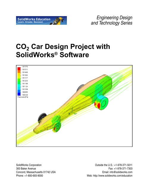
CO 2 <strong>Car</strong> Design <strong>Project</strong> with<br />
<strong>SolidWorks</strong> ® Software<br />
<strong>SolidWorks</strong> Corporation<br />
300 Baker Avenue<br />
Concord, Massachusetts 01742 USA<br />
Phone: +1-800-693-9000<br />
Engineering Design<br />
and Technology Series<br />
Outside the U.S.: +1-978-371-5011<br />
Fax: +1-978-371-7303<br />
Email: info@solidworks.com<br />
Web: http://www.solidworks.com/education
© 1995-2009, Dassault Systèmes<br />
Dassault Systèmes <strong>SolidWorks</strong> Corporation, a<br />
Dassault Systèmes S.A. company.<br />
300 Baker Avenue<br />
Concord, Mass. 01742 USA<br />
All Rights Reserved<br />
U.S. Patents 5,815,154; 6,219,049; 6,219,055;<br />
6,603,486; 6,611,725; 6,844,877; 6,898,560;<br />
6,906,712; 7,079,990; 7,184,044; and foreign<br />
patents, (e.g., EP 1,116,190 and JP 3,517,643). U.S.<br />
and foreign patents pending.<br />
The information and the software discussed in this<br />
document are subject to change without notice and<br />
are not commitments by Dassault Systèmes<br />
<strong>SolidWorks</strong> Corporation (DS <strong>SolidWorks</strong>).<br />
No material may be reproduced or transmitted in any<br />
form or by any means, electronic or mechanical, for<br />
any purpose other than normal educational<br />
instructional purposes (and excluding any<br />
commercial, competitive, or research use), without<br />
the express written permission of DS <strong>SolidWorks</strong>.<br />
The software discussed in this document is furnished<br />
under a license and may be used or copied only in<br />
accordance with the terms of this license. All<br />
warranties given by DS <strong>SolidWorks</strong> as to the<br />
software and documentation are set forth in the<br />
<strong>SolidWorks</strong> Corporation License and Subscription<br />
Service Agreement, and nothing stated in, or implied<br />
by, this document or its contents shall be considered<br />
or deemed a modification or amendment of such<br />
warranties.<br />
<strong>SolidWorks</strong>, 3D PartStream.NET, 3D<br />
ContentCentral, DWGeditor, PDMWorks,<br />
eDrawings, and the eDrawings logo are registered<br />
trademarks and FeatureManager is a jointly owned<br />
registered trademark of DS <strong>SolidWorks</strong>.<br />
Enterprise PDM and <strong>SolidWorks</strong> 2009 are product<br />
names of DS <strong>SolidWorks</strong>.<br />
FloXpress, DWGseries, DWGgateway, Feature<br />
Palette, PhotoWorks, TolAnalyst, and<br />
XchangeWorks are trademarks of DS <strong>SolidWorks</strong>.<br />
FeatureWorks is a registered trademark of<br />
Geometric Software Solutions Co. Ltd.<br />
Other brand or product names are trademarks or<br />
registered trademarks of their respective holders.<br />
Document Number: PME0617-ENG<br />
COMMERCIAL COMPUTER<br />
SOFTWARE - PROPRIETARY<br />
U.S. Government Restricted Rights. Use,<br />
duplication, or disclosure by the government is<br />
subject to restrictions as set forth in FAR 52.227-19<br />
(Commercial Computer Software - Restricted<br />
Rights), DFARS 227.7202 (Commercial Computer<br />
Software and Commercial Computer Software<br />
Documentation), and in the license agreement, as<br />
applicable.<br />
Contractor/Manufacturer:<br />
Dassault Systèmes <strong>SolidWorks</strong> Corporation, 300<br />
Baker Avenue, Concord, Massachusetts 01742 USA<br />
Portions of this software © 1990-2009 Siemens<br />
Product Lifecycle Management Software III (GB)<br />
Ltd.<br />
© 1998-2009 Geometric Software Solutions Co.<br />
Ltd.,<br />
© 1986-2009 mental images GmbH & Co. KG,<br />
© 1996-2009 Microsoft Corporation<br />
Outside In® Viewer Technology, © 1992-2009<br />
Stellent Chicago Sales, Inc.<br />
© 2000-2009 Tech Soft 3D<br />
© 1998-2009 3Dconnexion, IntelliCAD Technology<br />
Consortium, Independent JPEG Group. All Rights<br />
Reserved.<br />
Portions of this software incorporate PhysX by<br />
NVIDIA 2006 - 2009.<br />
Portions of this software are copyrighted by and are<br />
the property of UGS Corp. © 2009.<br />
Portions of this software © 2001 - 2009 Luxology,<br />
Inc. All Rights Reserved, Patents Pending.<br />
Copyright 1984-2009 Adobe Systems Inc. and its<br />
licensors. All rights reserved.<br />
Protected by U.S. Patents 5,929,866; 5,943,063;<br />
6,289,364; 6,563,502; 6,639,593; 6,754,382; Patents<br />
Pending.<br />
Adobe, the Adobe logo, Acrobat, the Adobe PDF<br />
logo, Distiller and Reader are registered trademarks<br />
or trademarks of Adobe Systems Inc. in the U.S. and<br />
other countries. For more copyright information, in<br />
<strong>SolidWorks</strong> see Help, About.<br />
Other portions of <strong>SolidWorks</strong> 2009 are licensed<br />
from DS <strong>SolidWorks</strong> licensors.<br />
All Rights Reserved.
<strong>SolidWorks</strong><br />
Engineering Design and Technology Series<br />
Table of Contents<br />
Lesson 1: Introduction .......................................................................................1<br />
Using This Book........................................................................................................... 2<br />
What is <strong>SolidWorks</strong> Software?..................................................................................... 2<br />
Prerequisites.................................................................................................................. 2<br />
Conventions Used in This Book................................................................................... 3<br />
Before You Begin......................................................................................................... 3<br />
Add the Folder to the Design Library Path ............................................................ 5<br />
Lesson 2: Exploring and Assembling the <strong>Car</strong> .................................................7<br />
What is Important When Designing a Dragster?.......................................................... 8<br />
About Balsa .................................................................................................................. 9<br />
Start <strong>SolidWorks</strong> and Open an Existing Part................................................................ 9<br />
Determining the Mass of the Blank............................................................................ 11<br />
Density ................................................................................................................. 11<br />
Calculating Volume ............................................................................................. 12<br />
Area of a Trapezoid ....................................................................................... 12<br />
Checking Our Math ....................................................................................... 13<br />
Volume of a Trapezoidal Prism..................................................................... 13<br />
Why is the Density 0.00?............................................................................... 14<br />
What About the Hole for the CO 2 <strong>Car</strong>tridge? ............................................... 15<br />
More to Explore.......................................................................................................... 17<br />
Converting Units .................................................................................................. 17<br />
Another Example ................................................................................................. 18<br />
So How Does This Apply to Density?........................................................... 19<br />
Summary .............................................................................................................. 20<br />
Creating an Assembly................................................................................................. 20<br />
Insert Mate.................................................................................................................. 23<br />
Planning Ahead .................................................................................................... 26<br />
Distance Mates .............................................................................................. 26<br />
i
ii<br />
<strong>SolidWorks</strong><br />
Engineering Design and Technology Series<br />
Lesson 3: Analyzing the <strong>Car</strong> Using <strong>SolidWorks</strong> Flow Simulation ...............31<br />
The Aerodynamics Analysis of the <strong>Car</strong>...................................................................... 32<br />
What is <strong>SolidWorks</strong> Flow Simulation?................................................................ 32<br />
Fluid Flow Analysis ............................................................................................. 32<br />
Why Do Design Analysis? ............................................................................ 33<br />
Check Before Using <strong>SolidWorks</strong> Flow Simulation....................................... 34<br />
<strong>SolidWorks</strong> Flow Simulation Toolbars ......................................................... 34<br />
Let’s Analyze the <strong>Car</strong> ................................................................................................. 35<br />
Create a Flow Simulation <strong>Project</strong> ........................................................................ 35<br />
Gram-force..................................................................................................... 36<br />
Using Symmetry................................................................................................... 41<br />
Computational Domain ........................................................................................ 43<br />
Modifying the Computational Domain.......................................................... 43<br />
Setting Goals ........................................................................................................ 45<br />
Running the Analysis ........................................................................................... 47<br />
Monitoring the Solution ....................................................................................... 48<br />
Viewing the Results.................................................................................................... 53<br />
Accessing the Results........................................................................................... 53<br />
Interpreting the Results ........................................................................................ 55<br />
Flow Trajectories........................................................................................... 56<br />
Experiment With Other Flow Trajectories .................................................... 57<br />
Quantitative Results ............................................................................................. 63<br />
Units, Values, and Interpreting the Results.......................................................... 64<br />
Conclusion .................................................................................................................. 64<br />
Lesson 4: Making Design Changes.................................................................65<br />
Changing the <strong>CO2</strong> <strong>Car</strong> Design ................................................................................... 66<br />
Configurations...................................................................................................... 66<br />
Modifying the Model.................................................................................................. 66<br />
Splines.................................................................................................................. 71<br />
The Anatomy of a Spline............................................................................... 71<br />
Sketching with Splines .................................................................................. 72<br />
Dimensioning Splines.................................................................................... 76<br />
Extruding an Open Contour ................................................................................. 78<br />
Modify the Underside of the <strong>Car</strong> ......................................................................... 83<br />
Reduction in Mass................................................................................................ 86<br />
Percentage Improvement ............................................................................... 87<br />
Assembly Configurations ........................................................................................... 87<br />
Lesson 5: Analyzing the Modified Design ......................................................91<br />
Analyze the Modified Design with Flow Simulation................................................. 92<br />
Examine the Results ................................................................................................... 93
<strong>SolidWorks</strong><br />
Engineering Design and Technology Series<br />
Flow Trajectories ................................................................................................. 94<br />
Quantitative Results ............................................................................................. 97<br />
Percentage Improvement ............................................................................... 98<br />
What About Lift?........................................................................................... 98<br />
Why Didn’t We See a Greater Reduction in Drag?....................................... 99<br />
Surface Parameters............................................................................................. 100<br />
What Does This Tell Us?............................................................................. 101<br />
Did Changing the Body Really Help? ......................................................... 102<br />
Replace the Rear Wheels.......................................................................................... 103<br />
Examine the Results........................................................................................... 105<br />
Percentage Improvement.................................................................................... 106<br />
More to Explore........................................................................................................ 107<br />
Lesson 6: Making Drawings of the <strong>Car</strong>.........................................................109<br />
Drawings................................................................................................................... 110<br />
Creating a Drawing and Views................................................................................. 110<br />
Using the Drawing to Build the <strong>Car</strong> ......................................................................... 120<br />
Auxiliary Views ................................................................................................. 121<br />
Adding Sheets to Drawings................................................................................ 122<br />
Reference Edge for Auxiliary View................................................................... 123<br />
Design Template.......................................................................................... 127<br />
Assembly Drawing............................................................................................. 127<br />
Fine Tuning the Drawing.......................................................................................... 131<br />
Lesson 7: PhotoWorks ...............................................................................133<br />
PhotoWorks .............................................................................................................. 134<br />
Creating a Rendering ................................................................................................ 135<br />
Make a Configuration for Rendering ................................................................. 137<br />
Lighting..................................................................................................................... 137<br />
Types of Lights .................................................................................................. 137<br />
Photographic Lighting........................................................................................ 138<br />
Appearances.............................................................................................................. 141<br />
Scenes ....................................................................................................................... 146<br />
Scene Editor ....................................................................................................... 146<br />
Rendering.................................................................................................................. 151<br />
Methods to Increase Screen Rendering Speed................................................... 151<br />
Reduce the Number of Pixels to Render ..................................................... 151<br />
Reduce the Complexity of the Rendering.................................................... 151<br />
Decals ....................................................................................................................... 153<br />
Masks ................................................................................................................. 154<br />
Masking Techniques.................................................................................... 154<br />
Selecting a Color ......................................................................................... 155<br />
iii
iv<br />
<strong>SolidWorks</strong><br />
Engineering Design and Technology Series<br />
What You Can’t See Doesn’t Matter........................................................... 157<br />
What Makes an Image Look Realistic?.................................................................... 159<br />
Reflections.......................................................................................................... 159<br />
Props................................................................................................................... 162<br />
We Need a Real Floor ................................................................................. 162<br />
Shadows ............................................................................................................. 168<br />
Output Options.......................................................................................................... 169<br />
Render to a Printer ............................................................................................. 169<br />
Rendering to a File............................................................................................. 169<br />
File Types .................................................................................................... 169<br />
Methods to Increase Rendering Quality ...................................................... 170<br />
How Many Pixels to Render........................................................................ 171<br />
Dpi Versus Ppi............................................................................................. 171<br />
Calculating Correct Number of Pixels......................................................... 171<br />
Example #1.................................................................................................. 171<br />
Example #2.................................................................................................. 172
<strong>SolidWorks</strong><br />
Engineering Design and Technology Series<br />
When you complete this lesson, you will be able to:<br />
Lesson 1<br />
Introduction<br />
Describe the relationship between Parts, Assemblies and Drawings;<br />
Identify the principal components of the <strong>SolidWorks</strong> user interface and<br />
toolbars;<br />
Identify the function of each mouse button when using <strong>SolidWorks</strong>.
Lesson 1: Introduction <strong>SolidWorks</strong><br />
Engineering Design and Technology Series<br />
Using This Book<br />
The <strong>CO2</strong> <strong>Car</strong> Design <strong>Project</strong> helps you learn the principles of testing<br />
aerodynamic performance using <strong>SolidWorks</strong> and Flow Simulation as an integral<br />
part of a creative and iterative design process.<br />
You will be learning by doing as you complete these phases of the project:<br />
Establish a baseline, or control car for aerodynamic testing. This car uses the<br />
unmodified blank as the body. The aerodynamic performance of the control<br />
car will serve as a reference for comparing and assessing the effects of<br />
changes to the car body’s shape.<br />
Set up a wind tunnel problem using Flow Simulation.<br />
Make modifications to the body of the car and rerun the aerodynamic testing.<br />
Create your own car body design and test it in the virtual wind tunnel.<br />
Refine the design of your car body based on the results of the aerodynamic<br />
testing and retest it.<br />
Create fully detailed drawings of your car design.<br />
Create an exploded view assembly drawing complete with a bill of materials.<br />
Create a photorealistic rendering of your final car design using PhotoWorks.<br />
What is <strong>SolidWorks</strong> Software?<br />
<strong>SolidWorks</strong> is design automation software. In <strong>SolidWorks</strong>, you sketch ideas and<br />
experiment with different designs to create 3D models using the easy to learn<br />
Windows ® graphical user interface.<br />
<strong>SolidWorks</strong> is used by students, designers, engineers and other professionals to<br />
produce simple and complex parts, assemblies and drawings.<br />
Prerequisites<br />
Before you begin the CO 2 <strong>Car</strong> Design <strong>Project</strong> you should complete the following<br />
online tutorials that are integrated in the <strong>SolidWorks</strong> software:<br />
Lesson 1 - Parts<br />
Lesson 2 - Assemblies<br />
Lesson 3 - Drawings<br />
You can access the online tutorials by clicking Help, Online Tutorial. The online<br />
tutorial resizes the <strong>SolidWorks</strong> window and runs beside it.<br />
2 Using This Book
<strong>SolidWorks</strong> Lesson 1: Introduction<br />
Engineering Design and Technology Series<br />
As an alternative, you can complete the following lessons from An Introduction to<br />
Engineering Design With <strong>SolidWorks</strong>:<br />
Lesson 1: Using the Interface<br />
Lesson 2: Basic Functionality<br />
Lesson 3: The 40-Minute Running Start<br />
Lesson 4: Assembly Basics<br />
Lesson 6: Drawing Basics<br />
Conventions Used in This Book<br />
This manual uses the following typographical conventions:<br />
Convention Meaning<br />
Bold Sans Serif <strong>SolidWorks</strong> commands and options appear in this style.<br />
For example, Insert, Boss means choose the Boss option<br />
from the Insert menu.<br />
Typewriter Feature names and file names appear in this style. For<br />
example, Sketch1.<br />
17 Do this step. The steps in the lessons are numbered in sans serif bold.<br />
Before You Begin<br />
If you have not done so already, copy the companion files for the lessons onto<br />
your computer before you begin this project.<br />
1 Start <strong>SolidWorks</strong>.<br />
Using the Start menu, start the <strong>SolidWorks</strong> application.<br />
Conventions Used in This Book 3
Lesson 1: Introduction <strong>SolidWorks</strong><br />
Engineering Design and Technology Series<br />
2 <strong>SolidWorks</strong> Content.<br />
Click Design Library to open the Design<br />
Library task pane.<br />
Click on <strong>SolidWorks</strong> Content to show the<br />
folders below it.<br />
Click on <strong>SolidWorks</strong> Educator<br />
Curriculum.<br />
Click <strong>CO2</strong> <strong>Car</strong> Design <strong>Project</strong>.<br />
Note: There may be more curriculum folders listed<br />
in addition to the <strong>CO2</strong> <strong>Car</strong> Design <strong>Project</strong>.<br />
The lower pane will display an icon<br />
representing a Zip file that contains the<br />
companion files for this project.<br />
3 Download the Zip file.<br />
Press Ctrl and click the icon.<br />
You will be prompted for a folder in which<br />
to save the Zip file.<br />
Ask your teacher where you should save the<br />
Zip file. Usually the C:\Temp folder is a<br />
good location.<br />
Tip: Remember where you saved it.<br />
4 Before You Begin
<strong>SolidWorks</strong> Lesson 1: Introduction<br />
Engineering Design and Technology Series<br />
4 Open the Zip file.<br />
Browse to the folder where you saved the Zip file in step 3.<br />
Double-click the <strong>CO2</strong> <strong>Car</strong> Design <strong>Project</strong>.zip file.<br />
5 Click Extract.<br />
Browse to the location where you want to save the files. The system will<br />
automatically create a folder named <strong>CO2</strong> <strong>Car</strong> Design <strong>Project</strong> in<br />
whatever location you specify. For example, you might want to save it in My<br />
Documents. Check with your teacher about where to save the files.<br />
You now have a folder named <strong>CO2</strong> <strong>Car</strong> Design <strong>Project</strong> on your disk. The data<br />
in this folder will be used in the exercises.<br />
Tip: Remember where you saved it.<br />
Add the Folder to the Design Library Path<br />
The Design Library is a convenient way to access the parts used in the exercises.<br />
It is more efficient than using File, Open and browsing for a file. All that is<br />
necessary is to add the <strong>CO2</strong> <strong>Car</strong> Design <strong>Project</strong> folder to the search path of the<br />
Design Library.<br />
1 Task pane.<br />
Click Design Library to open the Design Library task pane.<br />
2 Add folder.<br />
Click Add File Location .<br />
Browse to where you extracted the companion files in step 4 on page 5.<br />
Select the folder <strong>CO2</strong> <strong>Car</strong> Design <strong>Project</strong> and click OK.<br />
Before You Begin 5
Lesson 1: Introduction <strong>SolidWorks</strong><br />
Engineering Design and Technology Series<br />
3 Results.<br />
The contents of the <strong>CO2</strong> <strong>Car</strong> Design<br />
<strong>Project</strong> folder will now be accessible<br />
through the Design Library task pane.<br />
6 Before You Begin
<strong>SolidWorks</strong><br />
Engineering Design and Technology Series<br />
Lesson 2<br />
Exploring and Assembling the <strong>Car</strong><br />
When you complete this lesson, you will be able to:<br />
Describe three factors important to the performance of a CO 2 -powered<br />
dragster;<br />
Calculate the area of a solid’s planar face;<br />
Calculate the volume of a solid, and, when given the density, calculate the<br />
mass;<br />
Create a new assembly;<br />
Insert components;<br />
Add mating relationships between components.
Lesson 2: Exploring and Assembling the <strong>Car</strong> <strong>SolidWorks</strong><br />
Engineering Design and Technology Series<br />
What is Important When Designing a Dragster?<br />
Within the framework of the contest specifications, there are three factors to keep<br />
in mind when it comes to building a winning dragster. These are:<br />
Friction<br />
Energy used to overcome friction is energy that isn’t being used to accelerate<br />
your dragster. Sources of friction include:<br />
• Wheels and axles: if the wheels do not spin freely, the dragster will be slow.<br />
• Misaligned axles: if the axle holes are not drilled perpendicular to the<br />
centerline of the dragster, the dragster will have a tendency to turn to the left<br />
or right. This will cost you speed.<br />
• Misaligned screw eyes: if the screw eyes are not positioned and aligned<br />
properly, the guideline can drag on them, the dragster body, or the wheels.<br />
This can slow the dragster dramatically.<br />
• Bumps or imperfections in the rolling surface of the wheel. The more<br />
perfectly round and smooth the wheels are, the better they will roll.<br />
Mass<br />
Sir Issac Newton’s Second Law of Motion states that Force = mass x<br />
acceleration. There is a finite amount of thrust (or Force) produced by a CO 2<br />
cartridge. It stands to reason that a car with less mass will accelerate quicker<br />
and travel down the track faster. Reducing the mass of your dragster is one<br />
way to build a faster car. Keep in mind that the contest specifications may<br />
stipulate a minimum mass for the vehicle.<br />
Aerodynamics<br />
The air exerts a resistance, or drag, as the dragster tries to move through it. To<br />
minimize drag, your car should have a smooth, streamlined shape.<br />
Of these three factors – friction, mass, and aerodynamics – we will explore two:<br />
mass and aerodynamics, during this project.<br />
8 What is Important When Designing a Dragster?
<strong>SolidWorks</strong> Lesson 2: Exploring and Assembling the <strong>Car</strong><br />
Engineering Design and Technology Series<br />
About Balsa<br />
Balsa trees grow naturally in the humid rain<br />
forests of Central and South America. Its<br />
Ecuador<br />
natural range extends south from<br />
Guatemala, through Central America, to<br />
the north and west coast of South America<br />
as far as Bolivia. However, the small<br />
country of Ecuador on the western coast of<br />
South America, is the world’s primary<br />
source of balsa for model building.<br />
Balsa needs a warm climate with plenty of<br />
rainfall and good drainage. For that reason,<br />
the best stands of balsa usually appear on<br />
the high ground between tropical rivers.<br />
Ecuador has the ideal geography and<br />
climate for growing balsa trees.<br />
Balsa wood imported into North America is<br />
plantation grown. Don’t worry about<br />
destroying the rain forests by using balsa –<br />
it grows incredibly fast. In 6 to 10 years the<br />
tree is ready for harvesting, having reached a height of 18 to 28 meters (60 to 90<br />
feet) and a diameter of about 115 centimeters (45 inches). If left to continue<br />
growing, the new wood on the outside layers becomes very hard and the tree<br />
begins to rot in the center. Unharvested, a balsa tree may grow to a diameter of<br />
180 centimeters (6 feet) or more, but very little usable lumber can be obtained<br />
from a tree of this size.<br />
Use balsa wood with a clear conscience. The rain forests aren’t being destroyed to<br />
harvest it.<br />
Start <strong>SolidWorks</strong> and Open an Existing Part<br />
1 Start the <strong>SolidWorks</strong> application.<br />
From the Start menu, click All Programs, <strong>SolidWorks</strong>, <strong>SolidWorks</strong>.<br />
2 Task pane.<br />
Click Design Library to open the Design Library task pane.<br />
About Balsa 9
Lesson 2: Exploring and Assembling the <strong>Car</strong> <strong>SolidWorks</strong><br />
Engineering Design and Technology Series<br />
3 Open the <strong>CO2</strong> <strong>Car</strong> Blank.<br />
In the Design Library, click on the folder<br />
<strong>CO2</strong> <strong>Car</strong> Design <strong>Project</strong>.<br />
The contents of the folder appear in the<br />
lower portion of the Design Library<br />
window.<br />
Drag and drop the part named <strong>CO2</strong> <strong>Car</strong><br />
Blank into the graphics area of the<br />
<strong>SolidWorks</strong> window.<br />
4 Rollback the FeatureManager design tree.<br />
Drag the rollback bar upwards to a position right before<br />
(above) the Power Plant Chamber feature.<br />
10 Start <strong>SolidWorks</strong> and Open an Existing Part
<strong>SolidWorks</strong> Lesson 2: Exploring and Assembling the <strong>Car</strong><br />
Engineering Design and Technology Series<br />
5 Dimensions of the blank.<br />
Right-click the Annotations folder and select Show Feature Dimensions<br />
from the shortcut menu.<br />
6 Turn off the dimension display.<br />
Select Show Feature Dimensions again to turn off the dimension display.<br />
Determining the Mass of the Blank<br />
Mass is the amount of matter an object has. Calculating the mass is done by<br />
multiplying the density of the material times the volume of the object. So, to<br />
determine the mass of the car body blank, we need to know two things:<br />
The density of the material, in this case, balsa wood<br />
The volume of the blank<br />
Density<br />
The density of balsa wood ranges from 100 kg/m3 to 300 kg/m3 depending on a<br />
number of factors including where the tree was grown, how old the tree was when<br />
it was cut, what part of the tree the wood was cut from, and how dry the wood is.<br />
Typical, medium-density balsa wood is in the range of 140 kg/m3 to 192 kg/m3 .<br />
In this example, we use a density of 160 kg/m3 .<br />
Determining the Mass of the Blank 11
Lesson 2: Exploring and Assembling the <strong>Car</strong> <strong>SolidWorks</strong><br />
Engineering Design and Technology Series<br />
Calculating Volume<br />
The car body blank is a trapezoidal prism. To calculate the volume, multiply the<br />
area of the trapezoid by the depth of the prism.<br />
Area of a Trapezoid<br />
A trapezoid is a quadrilateral (a 4-sided figure) with exactly one pair of parallel<br />
sides.<br />
To determine the area of a trapezoid:<br />
1. Add the lengths of the 2 parallel sides.<br />
2. Divide the sum by 2 to get the average length of the parallel sides.<br />
3. Multiply this by the distance between the parallel sides.<br />
b1 + b2<br />
This can be written as: area = h × ⎛------------------ ⎞<br />
⎝ 2 ⎠<br />
where b1 and b2 are the two parallel sides and h is the distance between them.<br />
Substituting the dimensions of the car body blank, we get:<br />
20mm + 70mm<br />
area 305mm × ⎛------------------------------------ ⎞<br />
⎝ 2 ⎠<br />
305mm × 45mm 13,725mm 2<br />
= = =<br />
12 Determining the Mass of the Blank
<strong>SolidWorks</strong> Lesson 2: Exploring and Assembling the <strong>Car</strong><br />
Engineering Design and Technology Series<br />
Checking Our Math<br />
<strong>SolidWorks</strong> has tools for measuring values such as length and area as well as for<br />
calculating volume and mass.<br />
7 Measure.<br />
Click Tools, Measure, or click Measure<br />
on the Tools toolbar.<br />
Select the trapezoidal face of the car body<br />
blank.<br />
The area is given as 13,725 mm2 , which<br />
matches our calculation.<br />
8 Close the dialog box.<br />
Right-click in the graphics area and select Close<br />
Measure Dialog from the shortcut menu. Or, click<br />
the”x” in the upper right corner of the dialog box.<br />
Volume of a Trapezoidal Prism<br />
To calculate the volume, multiply the area of the trapezoidal face, 13,725 mm2 , by<br />
the depth, 42 mm, which we saw in step 5. Thus:<br />
13,725mm 2<br />
× 42mm 576,450mm 3<br />
=<br />
Determining the Mass of the Blank 13
Lesson 2: Exploring and Assembling the <strong>Car</strong> <strong>SolidWorks</strong><br />
Engineering Design and Technology Series<br />
9 <strong>SolidWorks</strong> mass properties<br />
calculations.<br />
Click Tools, Mass Properties, or<br />
click Mass Properties on the<br />
Tools toolbar.<br />
A window appears giving all sorts<br />
of information about the part,<br />
including its volume.<br />
Notice the volume equals 576,450<br />
cubic millimeters. This matches<br />
our calculations.<br />
The mass is 92.23 grams.<br />
Why is the Density 0.00?<br />
By default, the precision of the<br />
units in this part are set to two<br />
decimal places. That means a<br />
density of 0.00016 is displayed as<br />
0.00. This does not effect the<br />
accuracy of the calculations, only<br />
the display of the results.<br />
The number of decimal places in<br />
the report can be changed.<br />
10 Options.<br />
In the Mass Properties report window, click<br />
Options.<br />
Click Use custom settings.<br />
Under Decimal places, change the number to 5.<br />
Click OK.<br />
14 Determining the Mass of the Blank
<strong>SolidWorks</strong> Lesson 2: Exploring and Assembling the <strong>Car</strong><br />
Engineering Design and Technology Series<br />
11 Updated results.<br />
The values in the report window are automatically updated to display with five<br />
decimal places.<br />
12 Close.<br />
Click Close to close the report window.<br />
What About the Hole for the <strong>CO2</strong> <strong>Car</strong>tridge?<br />
The car body blank used when writing this <strong>book</strong> has a hole predrilled for the <strong>CO2</strong> cartridge. To accurately determine the volume and mass of the blank, this has to<br />
taken into account. That is, the volume of the hole has to be subtracted from the<br />
volume of the blank.<br />
Rather than deal with more complicated mathematics, we will use <strong>SolidWorks</strong> to<br />
do the calculation.<br />
Determining the Mass of the Blank 15
Lesson 2: Exploring and Assembling the <strong>Car</strong> <strong>SolidWorks</strong><br />
Engineering Design and Technology Series<br />
13 Roll forward.<br />
Drag the rollback bar downward to the position right below<br />
the feature named Power Plant Chamber.<br />
14 Repeat the mass property calculations.<br />
Click Tools, Mass Properties, or click Mass Properties<br />
on the Tools toolbar.<br />
The report window now indicates a mass of 89.66 grams<br />
and a volume of 560,427.88 cubic millimeters.<br />
16 Determining the Mass of the Blank
<strong>SolidWorks</strong> Lesson 2: Exploring and Assembling the <strong>Car</strong><br />
Engineering Design and Technology Series<br />
15 Roll forward.<br />
Drag the rollback bar downward to the bottom of the<br />
FeatureManager design tree.<br />
More to Explore<br />
What is the density of your balsa wood blank? To find out, follow this procedure:<br />
1. Using a scale that is accurate to ±0.1 grams, measure the mass of your car<br />
body blank. Write the value here:________________________________<br />
2. Divide the mass by the volume of 560,427.88 cubic millimeters that we<br />
Mass<br />
obtained in step 14. Remember: Density = -------------------<br />
Volume<br />
3. Write the value here:___________________________<br />
Converting Units<br />
A quantity is made of two parts: the magnitude and the units. For example, if you<br />
measure the length of something to be 42 mm long, then the magnitude is 42 and<br />
the unit is mm.<br />
The same quantity can be expressed in different ways. For example, the same<br />
length can be stated as 42 mm or 1.65 inches. The magnitude and units change but<br />
the quantity, that is the length, is the same. Quantities that represent the same<br />
thing are said to be equivalent. This is typically indicated by the = sign.<br />
The key to converting units is to understand that you are not changing the quantity<br />
– only changing the way it is expressed. If you had 10 pennies and you gave them<br />
to someone in exchange for a dime, you would still have the same amount of<br />
money. Just because you went from having 10 things called pennies to having one<br />
thing called a dime doesn’t mean you have less money. You just have fewer coins.<br />
Let’s look at the math: 10 pennies = 1 dime<br />
Note: We use the = sign because the quantities are equivalent.<br />
10 pennies<br />
Divide both sides of the equation by 1 dime: -------------------------<br />
1 dime<br />
=<br />
--------------- = 1<br />
1 dime 1 dime<br />
More to Explore 17
Lesson 2: Exploring and Assembling the <strong>Car</strong> <strong>SolidWorks</strong><br />
Engineering Design and Technology Series<br />
By this process we have progressed from an equivalent, 10 pennies<br />
10<br />
conversion factor, ------------------------pennies<br />
= 1<br />
1 dime<br />
= 1 dime , to a<br />
Tip: The best way to write a conversion factor is to have the number 1 on one side of<br />
the equals sign.<br />
This demonstrates that the conversion factor between pennies and dimes is just a<br />
specialized way of expressing the number 1.<br />
This leads to two important realizations:<br />
The key to converting units is to multiply by the right form of the number 1.<br />
When you multiply something by 1 you do not change its value.<br />
Another Example<br />
Suppose we want to convert 60 miles/hour to feet/second. First list the equivalents<br />
that you know (or can look up):<br />
1 mile = 5,280 feet;<br />
1 hour = 60 minutes;<br />
1 minute = 60 seconds.<br />
Tip: Remember that any of these can be written in reverse order. For example, 5,280<br />
feet = 1 mile.<br />
Now write them as conversions factors, fractions that equal 1. These are the<br />
specialized forms of the number 1 that we can use.<br />
<br />
<br />
<br />
5,280<br />
---------------------feet<br />
= 1<br />
1 mile<br />
-------------------------<br />
1 hour<br />
= 1<br />
60 minutes<br />
-------------------------<br />
1 minute<br />
= 1<br />
60 seconds<br />
Now write the equation where we multiply by various specialized forms of the<br />
number 1.<br />
60 miles 1 hour 1 minute 5,280 feet<br />
------------------- × ------------------------- × ------------------------- ×<br />
----------------------<br />
1 hour 60 minutes 60 seconds 1 mile<br />
Tip: Write the conversion factors so the units cancel out. Since we started with miles<br />
per hour, hours is in the denominator. That means the next conversion factor<br />
should have hours in the numerator. This in turn determines the arrangement of<br />
the next conversion factor, and so on.<br />
18 More to Explore
<strong>SolidWorks</strong> Lesson 2: Exploring and Assembling the <strong>Car</strong><br />
Engineering Design and Technology Series<br />
Cancel out the units and two of the 60 values:<br />
60<br />
------------------miles<br />
1 hour<br />
× ------------------------- -------------------------<br />
1 minute 5,280 feet<br />
× × ----------------------<br />
1 hour 60 minutes 60 seconds 1 mile<br />
This leaves us with feet per second, which is what we want:<br />
-------------------------<br />
5,280 feet<br />
= 88 feet per second<br />
60 seconds<br />
So How Does This Apply to Density?<br />
Convert the density you calculated for your balsa wood blank from g/mm 3 to kg/<br />
m 3 . You will need to use some or all of these conversion factors:<br />
1 kilogram = 1,000 grams;<br />
1 meter = 1,000 millimeters;<br />
1 cubic millimeter = 1 millimeter x 1 millimeter x 1 millimeter;<br />
1 cubic meter = 1 meter x 1 meter x 1 meter;<br />
1 cubic meter = 1,000 millimeters x 1,000 millimeters x 1,000 millimeters;<br />
For illustration purposes, we will use the density 0.00016 grams/mm3 that we<br />
obtained in step 11 on page 15.<br />
Write the equation where we multiply by various specialized forms of the<br />
number 1.<br />
0.00016 grams<br />
mm 3<br />
-----------------------------------<br />
-----------------------------<br />
1 kg 1,000<br />
×<br />
1,000 grams<br />
3 mm 3<br />
× --------------------------<br />
0.00016 grams<br />
Cancel out the units:<br />
mm 3<br />
----------------------------------- -----------------------------<br />
1 kg 1,000<br />
×<br />
1,000 grams<br />
3 mm 3<br />
m 3<br />
× --------------------------<br />
m 3<br />
0.00016 kg 1,000<br />
This leaves us with:<br />
Dividing out 1,000 from the numerator and denominator give us:<br />
3<br />
×<br />
1,000 m 3<br />
------------------------------------------------<br />
which is<br />
You Do It<br />
Take the density you calculated for your balsa wood blank (see page 17) and<br />
using the procedure above, convert it from grams/mm3 to kilograms/m3 0.00016 kg 1,000<br />
.<br />
2<br />
×<br />
m 3<br />
160 kg<br />
-----------------------------------------------m<br />
3<br />
---------------<br />
Write your answer here:_________________________________<br />
More to Explore 19
Lesson 2: Exploring and Assembling the <strong>Car</strong> <strong>SolidWorks</strong><br />
Engineering Design and Technology Series<br />
Summary<br />
When you multiply something by 1 you do not change its value.<br />
Conversion factors are equivalents, written as fractions that equal 1.<br />
The key to converting units is to multiply by the right form of the number 1.<br />
Sometimes you have to multiply by several different forms of the number 1.<br />
Creating an Assembly<br />
1 Create an assembly.<br />
Click Make Assembly from Part/Assembly on the Standard toolbar.<br />
2 Insert component.<br />
The Insert Component PropertyManager automatically<br />
appears.<br />
The <strong>CO2</strong> <strong>Car</strong> Blank part file is listed in the Open<br />
documents list.<br />
Be sure the Graphics preview option is selected.<br />
Select the <strong>CO2</strong> <strong>Car</strong> Blank.sldprt part file.<br />
3 Show origin.<br />
Click View, Origins to turn on the display of the origins.<br />
20 Creating an Assembly
<strong>SolidWorks</strong> Lesson 2: Exploring and Assembling the <strong>Car</strong><br />
Engineering Design and Technology Series<br />
4 Locate component.<br />
Move the cursor onto the origin and place the<br />
component at the origin by placing the cursor<br />
over the origin symbol. The double arrow symbol<br />
appears when the cursor is snapping to the origin.<br />
The part will appear in the assembly<br />
FeatureManager design tree as Fixed(f).<br />
Note: The initial component added to the assembly is<br />
Fixed by default. Once you have inserted a fixed<br />
component into position in an assembly it cannot<br />
be moved unless you float it.<br />
5 Isometric view.<br />
Click Isometric on the Standard Views toolbar.<br />
6 Save the assembly.<br />
Save the assembly under the name <strong>CO2</strong> <strong>Car</strong> Baseline in the <strong>CO2</strong> <strong>Car</strong><br />
<strong>Project</strong> folder.<br />
7 Add the front wheels.<br />
Drag and drop the Front Wheel from the Design Library window into the<br />
assembly window.<br />
Do not click OK yet. Continue with the next step.<br />
Creating an Assembly 21
Lesson 2: Exploring and Assembling the <strong>Car</strong> <strong>SolidWorks</strong><br />
Engineering Design and Technology Series<br />
8 Add another front wheel.<br />
Click in the graphics area to add a second wheel.<br />
9 Add the rear wheels.<br />
Drag and drop two copies of the Rear Wheel from the Design Library window<br />
into the assembly window.<br />
22 Creating an Assembly
<strong>SolidWorks</strong> Lesson 2: Exploring and Assembling the <strong>Car</strong><br />
Engineering Design and Technology Series<br />
10 Turn off the origins.<br />
Click View, Origins to toggle off the display of the origins.<br />
Insert Mate<br />
An assembly is a document in which two or more parts and other assemblies (subassemblies)<br />
are mated together. Parts and sub-assemblies are called components<br />
in an assembly. Mates are used to create relationships between components. Faces<br />
are the most commonly used geometry in mates. In this case the existing subassemblies<br />
are mated to build an assembly based on the car part you created.<br />
There are three types of mates, the Standard Mates, the Advanced Mates and<br />
the Mechanical Mates.<br />
Insert Mate 23
Lesson 2: Exploring and Assembling the <strong>Car</strong> <strong>SolidWorks</strong><br />
Engineering Design and Technology Series<br />
Standard Mates<br />
Coincident<br />
Parallel<br />
Perpendicular<br />
Tangent<br />
Concentric<br />
Distance<br />
Angle<br />
Advanced Mates<br />
Symmetric<br />
Width<br />
Path Mate<br />
Linear/Linear Coupler<br />
Distance/Angle Limit<br />
Advanced Mates<br />
Cam<br />
Hinge<br />
Gear<br />
Rack Pinion<br />
Screw<br />
Universal Joint<br />
24 Insert Mate
<strong>SolidWorks</strong> Lesson 2: Exploring and Assembling the <strong>Car</strong><br />
Engineering Design and Technology Series<br />
You can select many different types of geometry to create a mate:<br />
Faces<br />
Planes<br />
Edges<br />
Vertices<br />
Sketch lines and points<br />
Axes and Origins<br />
11 Mate one of the front wheels to the body of the car.<br />
Click Insert, Mate…, or click the Mate tool on the Assembly toolbar.<br />
12 Selections and preview.<br />
Select the cylindrical faces of<br />
the axle hole in the body and<br />
the hole in the wheel as<br />
indicated.<br />
Tip: Zoom and/or rotate the view<br />
to make it easier to select the<br />
faces you want to mate.<br />
The Mate pop-up toolbar<br />
appears to make selections<br />
easier by displaying the<br />
available mate types right in<br />
the graphics area. The mate types that are available vary by geometry selection<br />
and are the same as those that appear in the PropertyManager. Either the onscreen<br />
toolbar or PropertyManager can be used.<br />
Concentric is selected as the default and the results of the mate are previewed.<br />
Click Add/Finish Mate to accept the Concentric mate.<br />
Tip: When the mate is previewed, the mouse pointer changes to look like this:<br />
Clicking the right mouse button enters OK and applies the mate.<br />
.<br />
Insert Mate 25
Lesson 2: Exploring and Assembling the <strong>Car</strong> <strong>SolidWorks</strong><br />
Engineering Design and Technology Series<br />
Planning Ahead<br />
Now that we have the wheel mated<br />
so it is concentric with the axle hole,<br />
we have to control its position along<br />
the axis of the hole. In other words,<br />
how far out from the centerline of<br />
the car body is the wheel?<br />
At first thought it might make sense<br />
to add a Coincident mate between<br />
the side of the car body and the<br />
inner face of the hub of the wheel.<br />
However, this is not the best strategy. A Coincident mate requires two planes,<br />
either faces or reference planes. If we modify the shape of the car body so that the<br />
side is no longer planar, then the Coincident mate will fail.<br />
A better approach is to plan ahead and use a type of mate that will define the<br />
location of the wheel regardless of what happens to the shape of the car body. The<br />
best mate to use in this situation is a Distance mate.<br />
Distance Mates<br />
Distance mates are a bit more<br />
complicated than some other types of<br />
mates. The reason for this is when you<br />
specify a distance between two<br />
objects, there are two solutions.<br />
The illustrations at the right show a<br />
Or...<br />
front view of the car body and wheel.<br />
In the leftmost picture, the wheel is<br />
positioned 21.25mm to the right of the<br />
Right reference plane.<br />
In the rightmost picture, the wheel is<br />
positioned 21.25mm to the left of the Right reference plane.<br />
Both solutions are technically correct. However, only one is the solution we want.<br />
When you add a Distance mate, pay attention to the preview in the graphics<br />
window. If the previewed solution is not the one you want, click Flip<br />
Dimension on the Mate pop-up toolbar.<br />
26 Insert Mate
<strong>SolidWorks</strong> Lesson 2: Exploring and Assembling the <strong>Car</strong><br />
Engineering Design and Technology Series<br />
13 Add a Distance mate.<br />
The Mate PropertyManager<br />
stays active so you can<br />
continue adding mates without<br />
having to restart the command.<br />
In the FeatureManager design<br />
tree, expand the features of the<br />
<strong>CO2</strong> <strong>Car</strong> Blank and select<br />
the Right reference plane.<br />
Next select the planar face on<br />
the hub of the wheel.<br />
The system assumes you want a<br />
Coincident mate, which<br />
unfortunately is not what we<br />
want.<br />
Click Distance on the Mate<br />
pop-up toolbar and enter a distance value of 21.25 mm.<br />
Look at the preview to make sure the solution is correct.<br />
Click Add/Finish Mate to accept the mate.<br />
14 Mate the other front wheel.<br />
Select the cylindrical faces of the<br />
axle hoes in the body and wheel<br />
like you did in step 12.<br />
The system assumes you want a<br />
Concentric mate, which in this<br />
case is correct.<br />
However, the wheel is oriented<br />
the wrong way. This is because<br />
Concentric mates also have two<br />
solutions. By default, the system gives you the solution closest to the way the<br />
parts are already oriented. There are two ways to address this problem:<br />
1. Click Flip Mate Alignment on the Mate pop-up toolbar.<br />
2. Or, rotate the wheel around so it is more or less in the correct orientation<br />
before you add the mate.<br />
Insert Mate 27
Lesson 2: Exploring and Assembling the <strong>Car</strong> <strong>SolidWorks</strong><br />
Engineering Design and Technology Series<br />
15 Flip mate alignment.<br />
Since we have already started adding<br />
the Concentric mate, click Flip Mate<br />
Alignment on the Mate pop-up<br />
toolbar.<br />
The wheel rotates so it is aligned<br />
correctly.<br />
Click Add/Finish Mate to accept<br />
the mate.<br />
16 Add a Distance mate.<br />
Following the same procedure<br />
as in step 13, mate the wheel to<br />
the Right reference plane of<br />
the car body using a Distance<br />
mate.<br />
Because this wheel is located on<br />
the opposite side of the<br />
reference plane you should pay<br />
particular attention to the<br />
graphic preview. You may have<br />
to click Flip Dimension on<br />
the Mate pop-up toolbar to get<br />
the correct result.<br />
28 Insert Mate
<strong>SolidWorks</strong> Lesson 2: Exploring and Assembling the <strong>Car</strong><br />
Engineering Design and Technology Series<br />
17 Mate the rear wheels.<br />
Repeat step 12 through step 16 mating the rear wheels to the body of the car using<br />
Concentric and Distance mates.<br />
18 Mass calculation.<br />
Now that we have added the wheels to the assembly, what is the total mass?<br />
Click Tools, Mass Properties, or click Mass Properties on the Tools<br />
toolbar.<br />
The total mass is 107.29 grams.<br />
Is this correct?<br />
Not really. This assembly doesn’t contain any axles. We could increase the<br />
accuracy by modeling the steel axles and adding them to the assembly, but that is<br />
beyond the scope of this lesson. The point is, the accuracy of the calculations is no<br />
better than the accuracy of the models we create.<br />
19 Save the file.<br />
Turn off the RealView Graphics tool , if the RealView Graphics mode is on.<br />
Save the assembly file.<br />
Insert Mate 29
Lesson 2: Exploring and Assembling the <strong>Car</strong> <strong>SolidWorks</strong><br />
Engineering Design and Technology Series<br />
30 Insert Mate
<strong>SolidWorks</strong><br />
Engineering Design and Technology Series<br />
Lesson 3<br />
Analyzing the <strong>Car</strong> Using <strong>SolidWorks</strong><br />
Flow Simulation<br />
When you complete this lesson, you will be able to:<br />
Describe <strong>SolidWorks</strong> Flow Simulation;<br />
Describe a fluid flow analysis;<br />
Load the <strong>SolidWorks</strong> Flow Simulation add-in;<br />
Create a <strong>SolidWorks</strong> Flow Simulation project;<br />
Run an analysis on the car assembly;<br />
View the results.
Lesson 3: Analyzing the <strong>Car</strong> Using <strong>SolidWorks</strong> Flow Simulation <strong>SolidWorks</strong><br />
Engineering Design and Technology Series<br />
The Aerodynamics Analysis of the <strong>Car</strong><br />
32<br />
During this lesson, you will use <strong>SolidWorks</strong> Flow Simulation to analyze the<br />
aerodynamics of the car. Think of <strong>SolidWorks</strong> Flow Simulation as a virtual wind<br />
tunnel.<br />
What is <strong>SolidWorks</strong> Flow Simulation?<br />
<strong>SolidWorks</strong> Flow Simulation is the only fluid flow analysis tool for designers that<br />
is fully embedded inside <strong>SolidWorks</strong>. With this software you can analyze the<br />
solid model directly. You can also easily set up units, fluid type and fluid<br />
substances and more by using the wizard. The change operation to an analysis<br />
result is possible within the same GUI as the FeatureManager design tree in<br />
<strong>SolidWorks</strong>.<br />
There are several steps to the analysis:<br />
1. Create a design in <strong>SolidWorks</strong>.<br />
<strong>SolidWorks</strong> Flow Simulation can analyze parts, assemblies, subassemblies<br />
and multibodies.<br />
2. Create a project file in <strong>SolidWorks</strong> Flow Simulation.<br />
<strong>SolidWorks</strong> Flow Simulation projects will contain all the settings and results<br />
of a problem and each project that is associated with a <strong>SolidWorks</strong><br />
configuration.<br />
3. Run the analysis. This is sometimes called solving.<br />
4. Viewing the Flow Simulation results which include:<br />
Results Plots:<br />
- Vectors, Contours, Isolines<br />
- Cut Plots, Surface, Flow Trajectories, Isosurfaces<br />
Processed Results:<br />
- XY Plots (Microsoft Excel)<br />
- Goals (Microsoft Excel)<br />
- Surface Parameters<br />
- Point Parameters<br />
- Reports (Microsoft Word)<br />
- Reference Fluid Temperatures<br />
Fluid Flow Analysis<br />
Fluid Flow Analysis is used to dynamically study the action of liquids such as<br />
water and oil, or gases such as hydrogen and oxygen. The simulation of a weather<br />
report, tsunami information or auto traffic are phenomena of fluid flow analysis.<br />
The benefits of fluid flow analysis are Energy Conservation and Heat Transfer.
<strong>SolidWorks</strong> Lesson 3: Analyzing the <strong>Car</strong> Using <strong>SolidWorks</strong><br />
Flow Simulation<br />
Energy Conservation: The overall stress load of an engine can be lessened by<br />
analyzing its structure and weight, while a fluid flow analysis can gather<br />
combustion efficiency data to improve the power output.<br />
Heat Transfer refers to the physics of the exchange of energy in the form of<br />
temperature. For example, in a nuclear reactor, the radioactive degradation does<br />
not directly produce electrical energy. It is the heat energy which is transmitted<br />
into water to produce steam which drives the turbines to produce electricity.<br />
Fluid flow analysis is used in many fields of the manufacturing industry:<br />
Aerodynamic design and machine<br />
Fans and power generating windmills<br />
Cooling and heating<br />
Predicting the potency of a temperature transfer<br />
Fluid centered machines<br />
Pumps, compressors, and valves<br />
Electrical devices<br />
Personal computers and exothermic measurements of precise electrical<br />
devices<br />
Transport machinery<br />
<strong>Car</strong>s, ships and airplanes (engines are another)<br />
Why Do Design Analysis?<br />
After building your design in <strong>SolidWorks</strong>, you may need to answer questions like:<br />
Will the part run quickly?<br />
How will it handle air resistance?<br />
Can I use less material without affecting performance?<br />
In the absence of analysis tools, expensive prototype-test design cycles take place<br />
to ensure that the product’s performance meets customer expectations. Design<br />
analysis makes it possible to perform design cycles quickly and inexpensively on<br />
computer models instead. Even when manufacturing costs are not important<br />
considerations, design analysis provides significant product quality benefits,<br />
enabling engineers to detect design problems far sooner than the time it takes to<br />
build a prototype. Design analysis also facilitates the study of many design<br />
options and aids in developing optimized designs. Quick and inexpensive analysis<br />
often reveals non-intuitive solutions and benefits engineers by allowing them to<br />
better understand the product’s behavior.<br />
33
Lesson 3: Analyzing the <strong>Car</strong> Using <strong>SolidWorks</strong> Flow Simulation <strong>SolidWorks</strong><br />
Engineering Design and Technology Series<br />
Check Before Using <strong>SolidWorks</strong> Flow Simulation<br />
34<br />
Make sure <strong>SolidWorks</strong> Flow Simulation<br />
software is installed;<br />
Click Tools, Add-ins… and click<br />
<strong>SolidWorks</strong> Flow Simulation 2009 to<br />
load <strong>SolidWorks</strong> Flow Simulation.<br />
<strong>SolidWorks</strong> Flow Simulation Toolbars<br />
The <strong>SolidWorks</strong> Flow Simulation toolbars<br />
contain shortcuts for many commands. You can also access commands from the<br />
<strong>SolidWorks</strong> Flow Simulation pull-down menu.
<strong>SolidWorks</strong> Lesson 3: Analyzing the <strong>Car</strong> Using <strong>SolidWorks</strong><br />
Flow Simulation<br />
Let’s Analyze the <strong>Car</strong><br />
We will perform an aerodynamic analysis of the <strong>CO2</strong> car.<br />
1 Open the car assembly file.<br />
If the assembly is not already open from<br />
the previous lesson, click Open .<br />
From the Open window, browse to the<br />
<strong>CO2</strong> <strong>Car</strong> <strong>Project</strong> directory.<br />
Select <strong>CO2</strong> <strong>Car</strong> Baseline.sldasm,<br />
and click Open.<br />
2 Change the view orientation.<br />
If the part is not already in the isometric<br />
view, click on the Isometric tool on<br />
the Standard Views toolbar.<br />
Create a Flow Simulation <strong>Project</strong><br />
1 Click FloWorks, <strong>Project</strong>, Wizard...<br />
Or, click Wizard on the Flow Simulation Main toolbar.<br />
2 Configuration name for the project.<br />
Select Create new to create a new configuration and name it Control–55mph.<br />
Click Next.<br />
35
Lesson 3: Analyzing the <strong>Car</strong> Using <strong>SolidWorks</strong> Flow Simulation <strong>SolidWorks</strong><br />
Engineering Design and Technology Series<br />
Note: All required analysis data for this project is saved in this configuration, which is<br />
associated with <strong>SolidWorks</strong>.<br />
36<br />
3 Unit System.<br />
Choose SI(m-kg-s) in the Unit system area.<br />
In the Parameter window, under Main, set the Velocity to mile/h (miles per<br />
hour).<br />
Scroll down and under<br />
Loads&Motion, set Force to Gram<br />
force which is displayed as the<br />
symbol p.<br />
Click Next.<br />
Note: You can change the unit system<br />
anytime by clicking Flow<br />
Simulation, Units. You can also<br />
create your own custom unit system by clicking Create new.<br />
Gram-force<br />
Gram-force is a unit of force, approximately equal to the weight of a 1 gram mass<br />
on Earth. However, the local gravitational acceleration g varies with latitude,<br />
altitude and location on the planet. So to be precise, one gram-force is the force<br />
that a 1-gram mass exerts at a place where the acceleration due to gravity is<br />
9.80665 meters per second per second.
<strong>SolidWorks</strong> Lesson 3: Analyzing the <strong>Car</strong> Using <strong>SolidWorks</strong><br />
Flow Simulation<br />
4 Analysis Type and Physical Features.<br />
Select External as the Analysis type.<br />
Select the Exclude cavities without flow conditions and the Exclude internal<br />
space check boxes.<br />
For Reference axis, select Z.<br />
The reference axis is chosen so that an angular velocity vector can be aligned with<br />
the reference axis.<br />
Note: An internal analysis examines enclosed flow pathways while an external analysis<br />
examines open flow paths. You would use an internal analysis for something like<br />
an exhaust manifold for an automobile engine.<br />
Click Next.<br />
37
Lesson 3: Analyzing the <strong>Car</strong> Using <strong>SolidWorks</strong> Flow Simulation <strong>SolidWorks</strong><br />
Engineering Design and Technology Series<br />
38<br />
5 Default Fluid.<br />
Under Gases, select Air, and then click Add.<br />
TIP: You can also double-click Air, or drag and drop it from one list to the other.<br />
Note: Flow Simulation has a database library of several liquids and gases which is called<br />
the Engineering Database. With this database you can create your own materials.<br />
Flow Simulation can analyze either incompressible liquids or compressible gases<br />
but not both during the same run. You can also specify other advanced physical<br />
features which the program should take into account.<br />
Click Next.
<strong>SolidWorks</strong> Lesson 3: Analyzing the <strong>Car</strong> Using <strong>SolidWorks</strong><br />
Flow Simulation<br />
6 Wall Conditions.<br />
Use the default values of Adiabatic wall and a Roughness value of<br />
0 micrometer.<br />
Click Next.<br />
39
Lesson 3: Analyzing the <strong>Car</strong> Using <strong>SolidWorks</strong> Flow Simulation <strong>SolidWorks</strong><br />
Engineering Design and Technology Series<br />
7 Initial and Ambient Conditions.<br />
Under Velocity Parameters, double-click the value of Velocity in Z direction<br />
and type -55 mile/h.<br />
Note: The minus sign is important! It indicates that the air is flowing towards the car.<br />
40<br />
In the real world, the car would be moving through stationary air. In a wind<br />
tunnel, the car is stationary and the air is moving. You can think of this Flow<br />
Simulation example as a virtual wind tunnel – the car is stationary and the air is<br />
moving.<br />
Click Next.
<strong>SolidWorks</strong> Lesson 3: Analyzing the <strong>Car</strong> Using <strong>SolidWorks</strong><br />
Flow Simulation<br />
8 Results and Geometry Resolution.<br />
Set the Result resolution to 4 which will yield acceptably accurate results in a<br />
reasonable amount of time.<br />
Click Finish.<br />
9 Flow Simulation analysis tree.<br />
A tab for the Flow Simulation analysis tree is<br />
added to the FeatureManager area.<br />
Using Symmetry<br />
We can reduce the amount of time required for<br />
the analysis by taking advantage of the symmetry<br />
of the car. If you look at the car from the front<br />
view you can see that the right-hand side of the<br />
car is the mirror image of the left-hand side and<br />
that the Right reference plane splits the car<br />
down the middle. By specifying symmetry as one<br />
of the conditions of the computational domain,<br />
we only have to do half of the calculation.<br />
However, when using symmetry, there are some<br />
important things to keep in mind:<br />
1. This only works if the object being analyzed is indeed symmetrical.<br />
41
Lesson 3: Analyzing the <strong>Car</strong> Using <strong>SolidWorks</strong> Flow Simulation <strong>SolidWorks</strong><br />
Engineering Design and Technology Series<br />
42<br />
2. In this model we use half symmetry, therefore any forces you calculate will<br />
have to be doubled. For example, the magnitude of the force that represents<br />
drag on the car is actually only half the total force because only half of the car<br />
is analyzed.<br />
3. Neatness counts! Be sure the car body is built so it is centered with respect to<br />
the origin. And, be sure that when you added the car body to the assembly,<br />
you positioned it on the origin of the assembly as shown in step 4 on page 21.<br />
These two things are related. It doesn’t do you any good to position the body<br />
at the origin of the assembly if the body wasn’t built on the part’s origin in the<br />
first place.
<strong>SolidWorks</strong> Lesson 3: Analyzing the <strong>Car</strong> Using <strong>SolidWorks</strong><br />
Flow Simulation<br />
Computational Domain<br />
Flow Simulation calculations are performed inside<br />
a volume called the computational domain. The<br />
boundaries of this volume are parallel to the global<br />
coordinate system planes. For external flows, the<br />
size of the computational domain is automatically<br />
calculated based on the size of the model.<br />
In the illustration at the right, the black box<br />
represents the computational domain.<br />
Modifying the Computational Domain<br />
We will make changes to two aspects of the computational domain:<br />
Size<br />
We are going to reduce the size of the computational domain in order to<br />
reduce solving time, at the expense of accuracy. A smaller domain means<br />
there are fewer fluid cells to calculate. Using the default sizes for the domain<br />
could result in solving times in excess of 1.5 hours even on a moderately fast<br />
computer. Such solving times are not practical in a school environment.<br />
Boundary Conditions<br />
Changing the condition for the X minimum boundary is what defines the<br />
symmetry for this example.<br />
1 Show the analysis tree.<br />
Click on the Flow Simulation analysis tree tab .<br />
Expand the Input Data listing.<br />
43
Lesson 3: Analyzing the <strong>Car</strong> Using <strong>SolidWorks</strong> Flow Simulation <strong>SolidWorks</strong><br />
Engineering Design and Technology Series<br />
44<br />
2 Computational domain size.<br />
Right-click Computational<br />
Domain and select Edit<br />
Definition.<br />
On the Size tab, the values as<br />
listed below:<br />
X min = 0.0<br />
X max = 0.15 m<br />
Y min = - 0.006 m<br />
Y max = 0.2 m<br />
Z min = - 0.4 m<br />
Z max = 0.3 m<br />
Do not click OK yet. Continue with the next step.<br />
3 Computational domain boundary conditions.<br />
Click the Boundary Condition tab. Set At X min: to Symmetry.<br />
Click OK.<br />
4 Results.<br />
The resulting computational domain is shown in the illustrations below.
<strong>SolidWorks</strong> Lesson 3: Analyzing the <strong>Car</strong> Using <strong>SolidWorks</strong><br />
Flow Simulation<br />
Note: Reducing the size of our computational domain and utilizing a symmetry<br />
boundary condition will allow for more efficient calculations. We must always be<br />
sure, however, that our computational domain is large enough to allow our flow<br />
field to fully develop.<br />
Setting Goals<br />
You can specify the following four engineering goals:<br />
Global Goal<br />
A physical parameter calculated within the entire computational domain.<br />
Surface Goal<br />
A physical parameter calculated on a user-specified face of the model.<br />
Volume Goal<br />
A physical parameter calculated within a user-specified space inside the<br />
computational domain, either in the fluid or solid.<br />
Equation Goal<br />
A goal defined by an equation with the specified goals or parameters of the<br />
specified project’s input data features as variables.<br />
5 Insert global goals.<br />
Right click Goals in the Flow Simulation analysis<br />
tree and select the Insert Global Goals from the<br />
shortcut menu.<br />
45
Lesson 3: Analyzing the <strong>Car</strong> Using <strong>SolidWorks</strong> Flow Simulation <strong>SolidWorks</strong><br />
Engineering Design and Technology Series<br />
6 Setting the goal for drag.<br />
Drag the boundary of the<br />
PropertyManager window to the right<br />
to make it wider. This makes it easier<br />
to read the parameter names.<br />
In the Parameter list, find the<br />
parameter named Z - Component of<br />
Force.<br />
Tip: You will have to scroll down the list a<br />
ways.<br />
Click the check box.<br />
Click OK.<br />
46<br />
7 Insert a second global goal.<br />
Right click Goals again and select Insert Global Goals.
<strong>SolidWorks</strong> Lesson 3: Analyzing the <strong>Car</strong> Using <strong>SolidWorks</strong><br />
Flow Simulation<br />
8 Setting the goal for lift.<br />
In the Parameter list, find the<br />
parameter named Y - Component of<br />
Force.<br />
Click the check box.<br />
Click OK.<br />
9 Rename the goals.<br />
Two goal icons appear in the Flow<br />
Simulation analysis tree.<br />
Rename the Z component to Drag and<br />
the Y component to Lift.<br />
Running the Analysis<br />
This starts the calculation for the current project.<br />
10 Run the analysis.<br />
Right-click Control-<br />
55mph and click Run…, or<br />
click Flow Simulation , Solve,<br />
Run, or click Run Solver<br />
on the Flow Simulation<br />
toolbar.<br />
47
Lesson 3: Analyzing the <strong>Car</strong> Using <strong>SolidWorks</strong> Flow Simulation <strong>SolidWorks</strong><br />
Engineering Design and Technology Series<br />
48<br />
11 Solver information.<br />
The Solution Monitor window appears after a minute or so. On the left of the<br />
window is a log of each step taken in the solution process. On the right is an<br />
information window with mesh information and any warnings concerning the<br />
analysis.<br />
Monitoring the Solution<br />
The Solver window has its own toolbar that<br />
you can use to display the current results<br />
during the calculation.<br />
Stop<br />
Stops the calculation. You will be asked to save the current results. If you<br />
save the current results, you will be able to continue the calculation from the<br />
saved state rather than starting over.<br />
Suspend<br />
Suspends the calculation. When the calculations are suspended, you cannot<br />
modify either the model or Flow Simulation project,. However, CPU<br />
resources used by Flow Simulation are released.
<strong>SolidWorks</strong> Lesson 3: Analyzing the <strong>Car</strong> Using <strong>SolidWorks</strong><br />
Flow Simulation<br />
Information<br />
Displays mesh statistics, information<br />
about the current calculation step and<br />
number of iterations as well as<br />
warning messages if an inaccurate<br />
solution is possible.<br />
Goal Plot<br />
When you click Goal Plot , the<br />
Add/Remove Goals dialog appears.<br />
Select the goals whose plots you<br />
want to view and click OK.<br />
For each goal selected in the Add/Remove Goals dialog box, the Goal Plot<br />
shows the goal convergence diagram.<br />
49
Lesson 3: Analyzing the <strong>Car</strong> Using <strong>SolidWorks</strong> Flow Simulation <strong>SolidWorks</strong><br />
Engineering Design and Technology Series<br />
50<br />
Goal Table<br />
Shows the list of all specified goals. The Goal Table contains the same<br />
information as the upper portion of the Goal Plot window.<br />
Insert Preview<br />
Allows you to view the current results on the specified plane.<br />
12 Pause the calculation.<br />
After about 55 iterations, click Suspend on the Solver window’s toolbar.<br />
This pauses the calculation so you can explore some of the different types of<br />
previews.<br />
13 Preview the results.<br />
Click Insert Preview on<br />
the Solver window’s<br />
toolbar.<br />
The Preview Settings<br />
dialog box appears.<br />
For the Plane definition,<br />
select the Right Plane.<br />
For Mode, select Contours.<br />
Do not click OK yet.<br />
Continue with the next step.
<strong>SolidWorks</strong> Lesson 3: Analyzing the <strong>Car</strong> Using <strong>SolidWorks</strong><br />
Flow Simulation<br />
14 Settings.<br />
Click the Settings tab.<br />
For the Parameter, select<br />
Velocity.<br />
Click OK.<br />
15 Preview.<br />
The plot preview is displayed in its own window.<br />
51
Lesson 3: Analyzing the <strong>Car</strong> Using <strong>SolidWorks</strong> Flow Simulation <strong>SolidWorks</strong><br />
Engineering Design and Technology Series<br />
52<br />
16 Preview the pressure.<br />
Click Insert Preview on the Solver window’s toolbar.<br />
In the Preview Settings dialog box select the Right Plane for the Plane<br />
definition.<br />
For Mode, select Contours.<br />
Click the Settings tab.<br />
For the Parameter, select Pressure and click OK.<br />
17 Resume calculation.<br />
Click Suspend on the Solver window’s toolbar to resume the calculation.<br />
18 Completion.<br />
The status bar at the bottom<br />
of the window will indicate when the solver is finished.<br />
19 Close the Solver window.<br />
In the Solver window, click File, Close, or click the red X in the upper right<br />
corner of the window.<br />
20 Hide the computational domain.<br />
In the Flow Simulation analysis tree, right-click<br />
the Computational Domain icon and select<br />
Hide from the short cut menu. This hides the box<br />
that represents the size and position of the<br />
computational domain.<br />
21 Save the file.<br />
After investing time in running the analysis it is prudent to save your work.
<strong>SolidWorks</strong> Lesson 3: Analyzing the <strong>Car</strong> Using <strong>SolidWorks</strong><br />
Flow Simulation<br />
Viewing the Results<br />
Once the calculation finishes, you can view the saved calculation results through<br />
numerous Flow Simulation options in a customized manner directly within the<br />
graphics area. The results options are:<br />
Cut Plots (section view of parameter distribution)<br />
Surface Plots (parameter distribution on a selected surface)<br />
Isosurfaces<br />
Flow Trajectories (streamlines and particle trajectories)<br />
Goal Plot (behavior of the specified goals during the calculation)<br />
XY Plots (parameter change along a curve, sketch)<br />
Surface Parameters (getting parameters at specified surfaces)<br />
Point Parameters (getting parameters at specified points)<br />
Report (project report output into Microsoft Word)<br />
Animation of results<br />
We will view the surface plots and the flow trajectories next.<br />
Accessing the Results<br />
1 Load the results.<br />
Right-click Results in the Flow Simulation<br />
analysis tree and select Load Results.<br />
If Unload Results appears in the list, the results<br />
have already been loaded.<br />
The Load Results window opens.<br />
Select 1.fld and click Open to load the results<br />
file.<br />
Viewing the Results 53
Lesson 3: Analyzing the <strong>Car</strong> Using <strong>SolidWorks</strong> Flow Simulation <strong>SolidWorks</strong><br />
Engineering Design and Technology Series<br />
2 Change the view settings.<br />
Right-click Results and select View Settings.<br />
Type 100930 for the Min. pressure and 101575 for the Max. pressure.<br />
Click Apply, then OK.<br />
Note: The reason we do not use the default values is because if we make a design change<br />
to the car and rerun the analysis, the minimum and maximum pressure values will<br />
be different. That means red would represent one pressure on one plot and a<br />
different pressure on a different plot. Using the same minimum and maximum<br />
settings for each analysis allows for meaningful comparisons between different<br />
iterations of the design.<br />
3 Insert a surface plot.<br />
Right-click Surface Plots in the Flow Simulation<br />
analysis tree and select Insert.<br />
Select Use all faces.<br />
Under Display, click Contours.<br />
Click OK.<br />
54 Viewing the Results
<strong>SolidWorks</strong> Lesson 3: Analyzing the <strong>Car</strong> Using <strong>SolidWorks</strong><br />
Flow Simulation<br />
4 Surface plot results.<br />
The Surface Plot displays the pressure distribution on the selected model faces or<br />
<strong>SolidWorks</strong> surfaces.<br />
Only half of the car displays the colors because we used symmetry in the<br />
calculations. We assume the right-hand side of the car would be identical.<br />
Interpreting the Results<br />
Red indicates areas of high pressure. Blue indicates areas of low pressure. By<br />
looking at the surface plot we can see that the pressure is highest on the front face<br />
of the car body and on the front portion of the rear wheels.<br />
5 Hide the surface plot.<br />
Right-click Surface Plot 1 and select Hide. This hides the surface plot so we<br />
can more easily see the flow trajectories. You can always turn the surface plot<br />
back on later using Show.<br />
Viewing the Results 55
Lesson 3: Analyzing the <strong>Car</strong> Using <strong>SolidWorks</strong> Flow Simulation <strong>SolidWorks</strong><br />
Engineering Design and Technology Series<br />
Flow Trajectories<br />
Flow trajectories are another way to qualitatively view the results of the analysis.<br />
They are analogous to the streamers of smoke in a wind tunnel.<br />
6 Inserting a flow trajectory.<br />
Right-click Flow Trajectories in the Flow Simulation<br />
analysis tree, and select Insert.<br />
For Reference, press Ctrl and select the faces of the car<br />
body as shown:<br />
Front, top, and left side faces<br />
Faces that form the tread portion of the front and rear<br />
wheels<br />
Set the Number of trajectories to 50.<br />
For Draw trajectories as, select Line with Arrow.<br />
Leave the other settings at their default values.<br />
Click OK.<br />
56 Viewing the Results
<strong>SolidWorks</strong> Lesson 3: Analyzing the <strong>Car</strong> Using <strong>SolidWorks</strong><br />
Flow Simulation<br />
7 Resulting flow trajectory.<br />
This type of display helps visualize how the air flows around the car.<br />
Experiment With Other Flow Trajectories<br />
There are two ways to experiment with flow trajectories:<br />
Edit the definition of the existing plot<br />
Insert a new plot<br />
If you create multiple flow trajectories, you can display them one at a time or you<br />
can display several at the same time.<br />
We will create some other flow trajectories.<br />
8 Hide the flow trajectory.<br />
Right-click Flow Trajectories 1 and select Hide.<br />
Viewing the Results 57
Lesson 3: Analyzing the <strong>Car</strong> Using <strong>SolidWorks</strong> Flow Simulation <strong>SolidWorks</strong><br />
Engineering Design and Technology Series<br />
9 Insert a new flow trajectory.<br />
Right-click Flow Trajectories, and select Insert.<br />
For Reference, select the Right reference plane of the<br />
assembly.<br />
Set the Number of trajectories to 200.<br />
Click the Settings tab.<br />
For Draw trajectories as, select Line.<br />
Click OK.<br />
10 Right side view.<br />
Change the view to a right side orientation. Notice the<br />
turbulence behind the body of the car.<br />
11 Insert another new flow trajectory.<br />
Hide Flow Trajectories 2 and then insert<br />
a new flow trajectory.<br />
For Reference, select the surface that forms the<br />
tread of the front wheel.<br />
Set the Number of trajectories to 50.<br />
For Draw trajectories as, select Line.<br />
Click OK.<br />
58 Viewing the Results
<strong>SolidWorks</strong> Lesson 3: Analyzing the <strong>Car</strong> Using <strong>SolidWorks</strong><br />
Flow Simulation<br />
12 Change to an isometric view.<br />
The lower number of trajectory lines makes it easier to see if there is significant<br />
turbulence surrounding the front wheel. It appears that the narrow profile of the<br />
front wheel does not introduce much turbulence.<br />
13 Repeat for the rear wheel.<br />
Hide Flow Trajectories 3 and then insert a<br />
new flow trajectory.<br />
For Reference, select the surfaces that form the<br />
tread, sidewall, and hub of the front wheel.<br />
Set the Number of trajectories to 75.<br />
For Draw trajectories as, select Line.<br />
Click OK.<br />
Viewing the Results 59
Lesson 3: Analyzing the <strong>Car</strong> Using <strong>SolidWorks</strong> Flow Simulation <strong>SolidWorks</strong><br />
Engineering Design and Technology Series<br />
14 Change to an isometric view and zoom in.<br />
The flow trajectories reveal several conditions:<br />
The red color of the trajectories in front of the wheel indicate an area of high<br />
pressure. Perhaps a narrower wheel would reduce drag.<br />
There is turbulence in the area of the wheel hub.<br />
The flow trajectories behind the wheel are fairly smooth indicating a lack of<br />
turbulence.<br />
15 Edit definition.<br />
Right-click Flow Trajectories 4 and<br />
select Hide.<br />
Rotate the view so you can see the underside<br />
of the car body and the interior of the rear<br />
wheel.<br />
Then, right-click Flow Trajectories 4<br />
again and select Edit Definition.<br />
For Reference, select the surfaces that form<br />
the inside of the rear wheel and the wheel’s<br />
axle.<br />
Click OK.<br />
Reset the view to an isometric and zoom in on the rear wheel.<br />
Select these faces<br />
60 Viewing the Results
<strong>SolidWorks</strong> Lesson 3: Analyzing the <strong>Car</strong> Using <strong>SolidWorks</strong><br />
Flow Simulation<br />
It is hard to see the flow lines between the wheel and the car body because they<br />
are obscured by the geometry of the wheel.<br />
16 Transparency.<br />
Click Set Model Transparency on the Flow<br />
Simulation Display toolbar, or click FloWorks,<br />
Results, Display, Transparency.<br />
The Model Transparency dialog box appears.<br />
Click OK to use the default transparency value of<br />
0.50 (50%).<br />
Viewing the Results 61
Lesson 3: Analyzing the <strong>Car</strong> Using <strong>SolidWorks</strong> Flow Simulation <strong>SolidWorks</strong><br />
Engineering Design and Technology Series<br />
It is now easier to see the turbulence in the airflow between the wheel and car<br />
body.<br />
17 Turn off transparency.<br />
Click Set Model Transparency , or click FloWorks, Results, Display,<br />
Transparency.<br />
Drag the slider to set the transparency Value to 0.0.<br />
Click OK.<br />
18 Hide the flow trajectories plot.<br />
Right-click Flow Trajectories 4 and select Hide.<br />
62 Viewing the Results
<strong>SolidWorks</strong> Lesson 3: Analyzing the <strong>Car</strong> Using <strong>SolidWorks</strong><br />
Flow Simulation<br />
Quantitative Results<br />
The preceding examples of surface plots and flow trajectories were excellent tools<br />
for visualizing how the air flows around the car. However, they are more<br />
qualitative than quantitative. Let’s move on to a more quantitative interpretation<br />
of results.<br />
1 Create a goals plot.<br />
In the analysis tree,<br />
expand the Results<br />
listing and right-click<br />
Goals.<br />
Select Insert from the<br />
shortcut menu.<br />
Click Add All.<br />
Click OK.<br />
2 Excel spreadsheet.<br />
Microsoft ® Excel is<br />
launched and a<br />
spreadsheet opens. Pay particular attention to the first three columns. They show<br />
the name of the goal, the units (gram-force, in this case) and the value.<br />
Note: Remember! We used symmetry when doing the analysis so these values have to<br />
be doubled to obtain the correct value for the entire car.<br />
Note: We reformatted the column headers to make the columns narrower so we could fit<br />
the image on the page.<br />
Viewing the Results 63
Lesson 3: Analyzing the <strong>Car</strong> Using <strong>SolidWorks</strong> Flow Simulation <strong>SolidWorks</strong><br />
Engineering Design and Technology Series<br />
3 Save and close the assembly.<br />
Be sure to save the Excel spreadsheet when prompted.<br />
Units, Values, and Interpreting the Results<br />
As we discussed on page 36, gram-force is a unit of force approximately equal to<br />
the weight of a 1-gram mass on Earth. The drag on the car is a force. Grams are a<br />
unit of mass. So it is not accurate to say the drag is approximately 43.6 grams.<br />
The correct way to state the results is to say we have a drag force of approximately<br />
43.6 grams-force and a downward lift force of approximately 9.5 grams-force.<br />
Conclusion<br />
From the analysis, it is obvious that the car body blank right out of the box is not<br />
very aerodynamic. In the next lesson we will modify the shape of the body and<br />
rerun the analysis to determine the effects.<br />
64 Conclusion
<strong>SolidWorks</strong><br />
Engineering Design and Technology Series<br />
When you complete this lesson, you will be able to:<br />
Lesson 4<br />
Making Design Changes<br />
Create a configuration in a part;<br />
Use splines to sketch free-form shapes that cannot be represented using lines<br />
and arcs;<br />
Create extruded cuts using an open sketch contour;<br />
Use part configurations in an assembly.
Lesson 4: Making Design Changes <strong>SolidWorks</strong><br />
Engineering Design and Technology Series<br />
Changing the CO 2 <strong>Car</strong> Design<br />
Based on the analysis of the car using Flow Simulation, we conclude that the<br />
shape of the body needs to be redesigned to direct the air around the car with a<br />
more gradual and smoother changes in direction. We need to make the car<br />
rounder.<br />
Configurations<br />
Configurations allow you to represent more than one version of the part within a<br />
single <strong>SolidWorks</strong> file. For example, by suppressing the features and changing the<br />
dimension values of the model, the design can be altered easily without creating<br />
another new model. Any configuration may be changed to a dimension of a<br />
different value.<br />
Both parts and assemblies can support configuration adjustments.<br />
If a configuration is not created, the model which we create is saved automatically<br />
with a configuration named Default.<br />
Flow Simulation creates a configuration to store all analysis data. The name of<br />
this configuration is the name you entered in the Flow Simulation Wizard. In this<br />
case it is Control–55mph.<br />
Modifying the Model<br />
1 Open the <strong>CO2</strong> <strong>Car</strong> Blank part.<br />
Click Open , or click File, Open.<br />
Browse to the location of the <strong>CO2</strong> <strong>Car</strong> Blank, select it, and click Open.<br />
2 Switch to ConfigurationManager.<br />
Click the ConfigurationManager tab to change from<br />
the FeatureManager design tree to the<br />
ConfigurationManager.<br />
3 Add a new configuration.<br />
The current configuration is named Default. Rightclick<br />
on the file name and select Add Configuration.<br />
Type Design Variation 1 as the name.<br />
Under the Advanced Options, make sure that the<br />
Suppress new features and mates option is selected.<br />
Click OK to add the configuration.<br />
66 Modifying the Model
<strong>SolidWorks</strong> Lesson 4: Making Design Changes<br />
Engineering Design and Technology Series<br />
Note: Suppress is used to temporarily remove a feature. When<br />
a feature is suppressed, the system treats it as if it doesn’t<br />
exist. This means other features that are dependent on it<br />
will be suppressed also. Suppressed features can be<br />
unsuppressed at any time. The Suppress features option<br />
means that as new features are added, they are suppressed<br />
in all of the configurations except the active one.<br />
The new configuration is active. Any subsequent changes<br />
to the part are stored as part of the configuration.<br />
4 Create a new sketch.<br />
Select the Top reference plane and click Sketch .<br />
5 Top view orientation.<br />
Click Top on the Standard Views toolbar to change to<br />
the Top view orientation.<br />
6 View axes.<br />
Click View, Axes to display the axes that run through the<br />
center of the two axle holes. You will use these for<br />
references when sketching.<br />
7 Show hidden lines.<br />
Click Hidden Lines Visible on the View toolbar.<br />
This enables you see the location of Power Plant<br />
Chamber (the hole for the <strong>CO2</strong> cartridge) so you can<br />
maintain the minimum thickness surrounding it as required<br />
by the specifications.<br />
Modifying the Model 67
Lesson 4: Making Design Changes <strong>SolidWorks</strong><br />
Engineering Design and Technology Series<br />
8 Construction lines.<br />
Zoom in on the area around the Power Plant Chamber.<br />
Click Tools, Sketch Entities, Centerline, or click<br />
Centerline on the Sketch toolbar.<br />
Sketch a vertical construction line as shown at the right.<br />
Click Smart Dimension on the Sketch toolbar, or click<br />
Tools, Dimensions, Smart.<br />
Dimension the construction line to be 4mm from the edge of<br />
the hole for the <strong>CO2</strong> cartridge.<br />
9 Centerpoint arc.<br />
Zoom in on the front end of the car.<br />
Click Tools, Sketch Entities, Centerpoint Arc, or click Centerpoint Arc .<br />
Position the pointer to the right of the car body.<br />
Look for the Coincident pointer that indicates you are capturing a Coincident<br />
relation between the centerpoint of the arc and the axis.<br />
Click the mouse button to establish the centerpoint of the arc.<br />
Move the mouse to establish the starting point of the arc.<br />
Press and hold the mouse button and drag to define the length of the arc.<br />
The result should look like the arc shown in the rightmost illustration.<br />
Step 1: Locate the center Step 2: Define the radius Step 3: Define the arc length<br />
68 Modifying the Model
<strong>SolidWorks</strong> Lesson 4: Making Design Changes<br />
Engineering Design and Technology Series<br />
10 Tangent relation.<br />
Press Ctrl and select the edge of the car body and the<br />
arc. In the PropertyManager, select Tangent and<br />
click OK.<br />
11 Dimension the arc.<br />
Click Smart Dimension on the Sketch toolbar, or<br />
click Tools, Dimensions, Smart.<br />
Dimension the arc with a radius of 50mm.<br />
12 Sketch a line.<br />
Click Tools, Sketch Entities, Line, or click<br />
Line on the Sketch toolbar.<br />
Sketch a line from the endpoint of the arc to the<br />
edge of the car body as shown.<br />
Be careful not to snap to the midpoint of the car<br />
body edge.<br />
The line should be at an angle as shown. It<br />
should not be vertical and it should not be<br />
tangent to the arc.<br />
13 Sketch a construction line.<br />
Click Tools, Sketch Entities, Centerline, or<br />
click Centerline on the Sketch toolbar.<br />
Sketch a short, vertical construction line as<br />
shown, starting at the midpoint of the edge of the<br />
car body.<br />
Modifying the Model 69
Lesson 4: Making Design Changes <strong>SolidWorks</strong><br />
Engineering Design and Technology Series<br />
14 Mirror.<br />
Click Tools, Sketch Tools, Mirror, or click Mirror Entities on the Sketch<br />
toolbar.<br />
For Entities to mirror, select the arc and line.<br />
For Mirror about, select the construction line.<br />
Make sure Copy is selected. A preview indicates the results of the mirror<br />
operation.<br />
Click OK.<br />
15 Sketch a line.<br />
Click Tools, Sketch Entities, Line, or click Line on the<br />
Sketch toolbar.<br />
Sketch a line between the endpoints of the two angled lines.<br />
16 Dimensions.<br />
Click Smart Dimension on the Sketch toolbar,<br />
or click Tools, Dimensions, Smart.<br />
Dimension the length of the line you created in<br />
step 15 and set the value to 17mm.<br />
Dimension the angle between the two angled lines<br />
and set the value to 15°.<br />
Dimension the distance between the ends of the<br />
two arcs and set the value to 26.50mm.<br />
70 Modifying the Model
<strong>SolidWorks</strong> Lesson 4: Making Design Changes<br />
Engineering Design and Technology Series<br />
Splines<br />
Splines are used to sketch curves that<br />
have continuously changing shape.<br />
Splines are defined by a series points<br />
between which the <strong>SolidWorks</strong> software<br />
uses equations to interpolate the curve<br />
geometry. Splines are very useful for<br />
modeling free-form shapes that are<br />
smooth and fair. [Fair is a term often used in boat building. A “fair curve” is one<br />
that is as smooth as it can be as it follows the path it must take around the hull of a<br />
boat; it is free of extraneous bumps or hollows.]<br />
You can modify a spline by adding or deleting points, moving the points,<br />
dimensioning the points, changing tangency at the points, or adding geometric<br />
relations.<br />
Where to Find It<br />
Click Spline on the Sketch toolbar.<br />
Or, click Tools, Sketch Entities, Spline.<br />
The Anatomy of a Spline<br />
A spline in the <strong>SolidWorks</strong> software has several components and controls.<br />
Understanding what controls and analytical tools are available will help you get<br />
the most out of your splines.<br />
Endpoints<br />
Every spline has at least one<br />
endpoint. A closed loop spline<br />
has a single endpoint where<br />
the ends are tangent to one<br />
another. Open loop splines<br />
have two endpoints. An open<br />
loop spline can be converted<br />
to a closed loop spline by<br />
dragging one endpoint onto<br />
another, but a closed loop<br />
spline cannot be made open<br />
except by trimming.<br />
Spline Handle<br />
Endpoint<br />
Spline<br />
Polygon<br />
Spline Closed Loop<br />
Point<br />
Spline<br />
Spline Points<br />
Most splines use one or more interpolant spline points between the endpoints.<br />
Spline points can be added (through the right mouse menu) or deleted.<br />
Modifying the Model 71
Lesson 4: Making Design Changes <strong>SolidWorks</strong><br />
Engineering Design and Technology Series<br />
Spline Handles<br />
Spline handles are used to change the direction and magnitude of the tangency<br />
at a spline point or endpoint. Unless a handle is being used to create tangency<br />
other than the default settings, they are not visible unless the spline is<br />
selected.<br />
Spline handles at interior spline points can be dragged asymmetrically<br />
(handles to opposite sides of the point are independent), or by holding the Alt<br />
key, the handles will behave symmetrically.<br />
Spline handles are composed of magnitude and<br />
direction handles. The magnitude handle can be<br />
dragged in a direction tangent to the spline, and the<br />
direction handle can be dragged in a circle around<br />
Direction Handle<br />
the point to which it is attached. By dragging the dot<br />
at the end of the magnitude handle, you can control<br />
both magnitude and direction at the same time.<br />
Magnitude Handle<br />
Notice that the cursor changes to indicate which<br />
control it is over.<br />
Control Polygon<br />
The control polygon is the series of dotted lines that go around the spline. It<br />
can be used in place of handles to adjust the shape of the spline. To<br />
manipulate the control polygon, drag the control points (polygon vertices).<br />
Note: Moving the control polygon will move spline points while moving the spline<br />
handles will not.<br />
Sketching with Splines<br />
Here are some general guidelines you may find useful for working with splines:<br />
Smoothest curves<br />
Use as few spline points as possible to give<br />
the smoothest curve. Using many spline<br />
points usually only works if they are<br />
generated by a computer program. Manually<br />
tweaking points that are closely spaced can<br />
lead to lumpy or uneven splines.<br />
Combination Handle<br />
72 Modifying the Model
<strong>SolidWorks</strong> Lesson 4: Making Design Changes<br />
Engineering Design and Technology Series<br />
Point density<br />
You will need more spline points in areas of smaller radius. A long curving<br />
area will need relatively fewer points than a tightly curved section.<br />
All internal spline points are in<br />
this tightly curved area<br />
Two-point splines<br />
A two-point spline looks just like a straight line unless tangency is applied to<br />
the ends, in which case it becomes a very useful and flexible sketch tool. It is<br />
particularly useful in situations where a profile must change convexity, which<br />
an arc cannot do. Notice that this is much smoother than using a pair of<br />
tangent arcs.<br />
Two-point spline without tangency<br />
Two-point spline with tangency Two tangent arcs<br />
Tangency at endpoints<br />
By default, splines are created with no tangency at the endpoints. This means<br />
that splines tend to be flat or straight at their ends.<br />
Modifying the Model 73
Lesson 4: Making Design Changes <strong>SolidWorks</strong><br />
Engineering Design and Technology Series<br />
Procedure<br />
17 Sketch a spline.<br />
Click Spline on the Sketch toolbar, or, click<br />
Tools, Sketch Entities, Spline.<br />
Sketch a spline as shown in the illustration at the<br />
right. One end starts at the endpoint of the arc; the<br />
other end is at the end of the construction line. You<br />
want three internal spline points.<br />
Tip: When you get to the last point in the spline, doubleclick<br />
the mouse the end the spline.<br />
18 Add relation.<br />
Add a Coincident relation between the spline point<br />
and the axis of the rear axle hole.<br />
19 Add another relation.<br />
Add a second Coincident relation between the spline<br />
point and the edge of the car body.<br />
74 Modifying the Model
<strong>SolidWorks</strong> Lesson 4: Making Design Changes<br />
Engineering Design and Technology Series<br />
20 Add a relation to spline handle.<br />
Select the spline. This makes the spline handles appear.<br />
Select the spline handle by clicking the diamond-shaped direction handle.<br />
Add a Vertical relation.<br />
Select this<br />
Before After<br />
21 Spline tangency.<br />
Press Ctrl and select the construction line and the spline.<br />
Add a Tangent relation.<br />
Before After<br />
Note: You do not need to add any relations to the tangent handles on the other two spline<br />
points. Leave them at their default settings.<br />
22 Turn off the display of the spline handles.<br />
Right-click the spline and clear the Show Spline Handles<br />
option on the short cut menu.<br />
Modifying the Model 75
Lesson 4: Making Design Changes <strong>SolidWorks</strong><br />
Engineering Design and Technology Series<br />
23 Mirror the spline.<br />
Click Tools, Sketch Tools, Mirror, or click Mirror<br />
Entities on the Sketch toolbar.<br />
For Entities to mirror, select the spline.<br />
For Mirror about, select the construction line.<br />
Make sure Copy is selected. A preview indicates the<br />
results of the mirror operation.<br />
Click OK.<br />
Dimensioning Splines<br />
It is common practice to leave splines under defined.<br />
Fully dimensioning splines require two dimensions,<br />
or a combination of dimensions and sketch relations,<br />
for each spline point. When a spline is fully defined,<br />
it is much harder to make changes to it.<br />
However, in this case we will fully dimension the<br />
splines. Otherwise, the shape of the car you are<br />
working on would be different than the one<br />
illustrated in the <strong>book</strong> and your analysis results would be different.<br />
24 Dimension the splines.<br />
Starting at the end of the car where the <strong>CO2</strong> cartridge<br />
goes, dimension the splines as shown.<br />
Because of the symmetry imposed by the mirroring<br />
operation, you only have to apply the 35.70mm<br />
dimension to one of the splines. The spline point on<br />
the other spline will automatically line up.<br />
76 Modifying the Model
<strong>SolidWorks</strong> Lesson 4: Making Design Changes<br />
Engineering Design and Technology Series<br />
25 Finish dimensioning the splines.<br />
The spline point at the rear axle is already fully<br />
defined by the Coincident sketch relations. There<br />
is no need to dimension it. In fact, dimensioning it<br />
would make the sketch over defined.<br />
The sketch should now be fully defined.<br />
26 Shaded view.<br />
Click Shaded with Edges on the View<br />
toolbar.<br />
This will make it easier to see the preview when<br />
we extrude a cut feature using the sketch.<br />
27 Isometric view.<br />
Change the view back to the Isometric view.<br />
Modifying the Model 77
Lesson 4: Making Design Changes <strong>SolidWorks</strong><br />
Engineering Design and Technology Series<br />
Extruding an Open Contour<br />
The sketch we just completed is an open contour because we did not sketch a line<br />
between the endpoints of the two splines.<br />
Extruding an open contour makes the Extruded Cut feature behave in a slightly<br />
different way than you are used to:<br />
Both end conditions are automatically set to Through All.<br />
You have to pay attention to which side of the contour is cutting away the<br />
solid. A preview arrow in the graphics window points to the side of the<br />
contour where the material will be removed. To change the direction either<br />
click the arrow, or click Flip side to cut in the PropertyManager.<br />
Preview arrow<br />
28 Extrude a cut.<br />
Click Extruded Cut on the Features toolbar, or click Insert, Cut, Extrude.<br />
Click Flip side to cut so the material outside the contour is removed.<br />
Click OK.<br />
78 Modifying the Model
<strong>SolidWorks</strong> Lesson 4: Making Design Changes<br />
Engineering Design and Technology Series<br />
29 Results.<br />
The results are shown below.<br />
30 Add fillet.<br />
Click Fillet and set the Radius to 25mm and select the<br />
edges as shown.<br />
Click OK.<br />
31 Add another fillet.<br />
Click Fillet again and set the Radius to 15mm<br />
and select the edges as shown.<br />
Click OK.<br />
32 Save your work.<br />
Click File, Save, or click Save on the Standard<br />
toolbar.<br />
Tip: It is always good practice to save your work after you have created something you<br />
want to keep, or just before you try something you aren’t sure is going to work.<br />
Modifying the Model 79
Lesson 4: Making Design Changes <strong>SolidWorks</strong><br />
Engineering Design and Technology Series<br />
33 Create a new sketch.<br />
Select the Right reference plane and click Sketch .<br />
34 Show hidden lines.<br />
Click Hidden Lines Visible on the View toolbar.<br />
This enables you see the location of Power Plant Chamber (the hole for the<br />
<strong>CO2</strong> cartridge) so you can maintain the minimum thickness surrounding it as<br />
required by the specifications.<br />
35 Right view orientation.<br />
Click Right on the Standard Views toolbar to change to the Right view<br />
orientation.<br />
36 Construction lines.<br />
Click Tools, Sketch Entities, Centerline, or click Centerline on the Sketch<br />
toolbar.<br />
Sketch a horizontal construction line extending from the rear of the car body as<br />
shown below.<br />
Sketch a second construction line extending from the front of the car body. This<br />
construction line is not horizontal. Rather is extends downward at an angle.<br />
Note: Make sure you to not snap to the midpoint of the front edge of the car.<br />
Click Smart Dimension on the Sketch toolbar, or click Tools, Dimensions,<br />
Smart.<br />
Dimension the construction lines as shown in the illustration below.<br />
80 Modifying the Model
<strong>SolidWorks</strong> Lesson 4: Making Design Changes<br />
Engineering Design and Technology Series<br />
37 Two-point spline.<br />
Click Spline on the Sketch toolbar, or click Tools, Sketch Entities,<br />
Spline.<br />
Sketch a two-point spline between the endpoints of the two construction lines.<br />
Notice the spline looks exactly like a straight line. That will change when we add<br />
relations to the tangency handles.<br />
38 Horizontal relation.<br />
Select the spline. This makes the spline handles appear.<br />
Add a Horizontal relation to the spline handle at the rear of the car. Notice how<br />
this makes the spline curve.<br />
39 Tangent relation.<br />
Press Ctrl and select the construction line at the front of the car body and the<br />
spline.<br />
Add a Tangent relation.<br />
Modifying the Model 81
Lesson 4: Making Design Changes <strong>SolidWorks</strong><br />
Engineering Design and Technology Series<br />
40 Adjust the length of the spline handles.<br />
Making the spline handles longer increases the effect they have on the shape of<br />
the spline.<br />
Experiment by dragging the spline handles. Notice how the shape of the spline<br />
changes.<br />
While this is very interactive, it is not precise. There are two ways to precisely<br />
control the length of the spline handles:<br />
Dimension them<br />
Specify their length in the PropertyManager<br />
41 Dimension the spline handles.<br />
Click Smart Dimension on the Sketch<br />
toolbar, or click Tools, Dimensions,<br />
Smart.<br />
Select the diamond-shaped direction handle<br />
at the rear of the car body. Then click in the<br />
blank area of the graphics window to place<br />
the dimension.<br />
Set the value to 485.<br />
Repeat this process for the tangent handle at the front of the car body making the<br />
length value 470.<br />
82 Modifying the Model
<strong>SolidWorks</strong> Lesson 4: Making Design Changes<br />
Engineering Design and Technology Series<br />
42 Extrude a cut.<br />
Click Extruded Cut on the Features<br />
toolbar, or click Insert, Cut, Extrude.<br />
Verify that the cut is removing material<br />
from the correct side.<br />
Click OK.<br />
The results are shown below.<br />
Modify the Underside of the <strong>Car</strong><br />
43 Create a new sketch.<br />
Select the Right reference plane and click Sketch .<br />
44 View setup.<br />
Click Hidden Lines Visible on the View toolbar.<br />
Click Right on the Standard Views toolbar to change to the Right view<br />
orientation.<br />
Modifying the Model 83
Lesson 4: Making Design Changes <strong>SolidWorks</strong><br />
Engineering Design and Technology Series<br />
45 Construction line.<br />
Click Tools, Sketch Entities, Centerline, or click<br />
Centerline on the Sketch toolbar.<br />
Sketch a horizontal construction line extending from the<br />
rear of the car body as shown below.<br />
Dimension the construction line to be 10mm from the<br />
edge of the hole for the <strong>CO2</strong> cartridge.<br />
46 Two-point spline.<br />
Click Spline on the Sketch toolbar, or click Tools, Sketch Entities,<br />
Spline.<br />
Sketch a two-point spline between the endpoint of the construction line and the<br />
front corner of the car body.<br />
47 Tangent relation.<br />
Add a Tangent relation between the spline and the bottom edge of the car body.<br />
Dimension the length of the handle to be 750.<br />
48 Horizontal relation.<br />
Add a Horizontal relation to the spline handle at the rear of the car.<br />
Dimension the length of the handle to be 150.<br />
84 Modifying the Model
<strong>SolidWorks</strong> Lesson 4: Making Design Changes<br />
Engineering Design and Technology Series<br />
49 Extrude a cut.<br />
Click Extruded Cut on the Features<br />
toolbar, or click Insert, Cut, Extrude.<br />
Verify that the cut is removing material from<br />
the correct side.<br />
Click OK.<br />
The results are shown below.<br />
50 Fillet.<br />
Click Fillet and set the Radius to 5mm and select<br />
the edges as shown.<br />
Click OK.<br />
51 Fillet.<br />
Click Fillet and set the Radius to 14mm and select<br />
the edges as shown.<br />
Click OK.<br />
Modifying the Model 85
Lesson 4: Making Design Changes <strong>SolidWorks</strong><br />
Engineering Design and Technology Series<br />
52 Fillet.<br />
Click Fillet and set the Radius to<br />
5mm and select the edges as shown.<br />
Click OK.<br />
Tip: The option Tangent propagation in the<br />
Fillet command will select a chain of<br />
connected edges provided they are<br />
tangent to each other. This simplifies<br />
creating this fillet because you don’t<br />
have to manually select all the edges.<br />
53 Complete.<br />
The results of the design changes are<br />
shown at the right.<br />
Reduction in Mass<br />
What is the mass of the new body design? Remember, not only do we want to<br />
improve the aerodynamics, we want to reduce the mass.<br />
1 Mass properties calculations.<br />
What is the mass of the new body design?<br />
Click Tools, Mass Properties, or click Mass Properties on the Tools<br />
toolbar.<br />
The mass is 51.53 grams. How does that compare to the mass of the out-of-thebox<br />
blank?<br />
2 Switch configurations.<br />
In the ConfigurationManager, doubleclick<br />
the configuration named Default.<br />
Click Tools, Mass Properties, or click<br />
Mass Properties on the Tools<br />
toolbar.<br />
The mass is 89.53 grams.<br />
86 Modifying the Model
<strong>SolidWorks</strong> Lesson 4: Making Design Changes<br />
Engineering Design and Technology Series<br />
Percentage Improvement<br />
To find the percentage of improvement use this formula:<br />
⎛InitialValue --------------------------------------------------------------------<br />
– FinalValue⎞<br />
⎝ InitialValue ⎠<br />
× 100=<br />
PercentageChange<br />
89.53<br />
--------------------------------<br />
– 51.53<br />
× 100=<br />
42.44<br />
89.53<br />
3 Save and close the part file.<br />
Assembly Configurations<br />
The change yielded about a 42% reduction in mass.<br />
We have created a configuration in the part. Next we will create a configuration in<br />
the assembly to show the car before and after the changes.<br />
1 Reopen the assembly.<br />
When you reopen the assembly, the latest version of the car will not be<br />
referenced; all of the changes you just made will not be present.<br />
Note: If you did not close the assembly at the end of Lesson 3, you will get a message<br />
when the assembly window become visible. The changes to the car are detected<br />
and <strong>SolidWorks</strong> asks if you want to rebuild the assembly.<br />
Models contained within the assembly have changed. Would<br />
you like to rebuild the assembly now?<br />
Click Yes.<br />
2 Switch to the<br />
ConfigurationManager.<br />
Click the ConfigurationManager tab<br />
to change to the<br />
ConfigurationManager.<br />
The active configuration is the one we created when doing the initial Flow<br />
Simulation analysis: Control-55mph.<br />
3 Switch back to the default<br />
configuration.<br />
Position the cursor over the<br />
Default configuration and doubleclick<br />
it to make it active.<br />
The Flow Simulation analysis tree tab disappears because the default<br />
configuration does not have any analysis data associated with it.<br />
Assembly Configurations 87
Lesson 4: Making Design Changes <strong>SolidWorks</strong><br />
Engineering Design and Technology Series<br />
4 Add a new configuration.<br />
Right-click on the file name and select Add<br />
Configuration.<br />
The Add Configuration PropertyManager<br />
appears.<br />
For Configuration name, type the name<br />
<strong>Car</strong> Design Version 1.<br />
Expand the Advanced Options list.<br />
Click the Suppress new components option.<br />
When this option is selected, new components<br />
added to other configurations are suppressed in this configuration.<br />
Click OK.<br />
5 Results.<br />
A new configuration is added to<br />
the assembly.<br />
However, the new configuration is<br />
identical to the Default<br />
configuration.<br />
We need to change it so that this configuration shows the modified car body.<br />
88 Assembly Configurations
<strong>SolidWorks</strong> Lesson 4: Making Design Changes<br />
Engineering Design and Technology Series<br />
6 Referencing a different configuration.<br />
Switch back to the FeatureManager design tree.<br />
Right-click on the <strong>CO2</strong> <strong>Car</strong> Blank component in the FeatureManager design<br />
tree and select Component Properties .<br />
In the Referenced configuration area, select Design Variation 1.<br />
Click OK.<br />
Assembly Configurations 89
Lesson 4: Making Design Changes <strong>SolidWorks</strong><br />
Engineering Design and Technology Series<br />
7 Results.<br />
The assembly now shows<br />
the modified design of the<br />
car body.<br />
The image at the right<br />
shows RealView<br />
Graphics and<br />
Shadows in Shaded<br />
Mode .<br />
Note: Some graphics cards will<br />
not support RealView<br />
graphics.<br />
90 Assembly Configurations
<strong>SolidWorks</strong><br />
Engineering Design and Technology Series<br />
Lesson 5<br />
Analyzing the Modified Design<br />
When you complete this lesson, you will be able to:<br />
Clone a Flow Simulation project thus creating a template that can be used<br />
throughout the design process;<br />
Create assembly<br />
Reanalyze the model.
Lesson 5: Analyzing the Modified Design <strong>SolidWorks</strong><br />
Engineering Design and Technology Series<br />
Analyze the Modified Design with Flow Simulation<br />
The easiest way to redo the analysis is to clone the Flow Simulation project we<br />
created for the initial design. This way we don’t have to repeat the work of adding<br />
the goals, defining the computational domain, and adding the various results plots.<br />
1 Activate the analysis configuration Control–55mph.<br />
In the ConfigurationManager, double-click the configuration named Control-<br />
55mph. This is the fastest and easiest way to switch between configurations.<br />
The Flow Simulation analysis tree tab reappears.<br />
2 Switch to the analysis tree.<br />
Click the Flow Simulation analysis tree tab to access the analysis features.<br />
3 Clone project.<br />
Right-click the uppermost feature,<br />
Control-55mph, and select Clone <strong>Project</strong><br />
from the shortcut menu.<br />
In the Clone <strong>Project</strong> dialog box, click Add to<br />
existing.<br />
From the Existing configurations list, select<br />
<strong>Car</strong> Design Version 1.<br />
Select the Copy results option and click OK.<br />
4 Messages.<br />
When you click OK, you will get a couple of messages:<br />
Computational Domain<br />
The system will ask you if you want to reset the computational domain. Click No.<br />
To make it easier to do meaningful comparisons between the two sets of results,<br />
we want to use the same size computational domain. Also, resetting the domain<br />
would require us to redefine the symmetry conditions. That would be extra work.<br />
Mesh Settings<br />
92 Analyze the Modified Design with Flow
<strong>SolidWorks</strong> Lesson 5: Analyzing the Modified Design<br />
Engineering Design and Technology Series<br />
The geometry of the car body has changed. We’ve rounded the nose and made<br />
other changes. The mesh should be reset.<br />
Click Yes.<br />
5 Run the solver.<br />
In the Flow Simulation analysis tree , right-click the uppermost feature, <strong>Car</strong><br />
Design Version 1, and select Run from the shortcut menu.<br />
Examine the Results<br />
1 Load the results.<br />
If the results were not loaded automatically, right-click Results in the Flow<br />
Simulation analysis tree and select Load Results from the shortcut menu.<br />
2 Show the surface plot.<br />
Expand Surface Plots.<br />
Right-click Surface Plot 1, and select Show.<br />
3 Surface plot results.<br />
For comparison purposes in this lesson, we have also shown the surface plot for<br />
the initial design.<br />
Changed Design Baseline Design<br />
The drag force is equal to the pressure multiplied by the area. You can see in the<br />
surface plots of the two designs that rounding off the nose of the body results in a<br />
much smaller area of high pressure. This means we have reduced the drag force<br />
on the body of the car. However, we have areas of high pressure on the front<br />
portions of the wheels, particularly the rear wheels. We will discuss this in more<br />
detail later in this lesson.<br />
Examine the Results 93
Lesson 5: Analyzing the Modified Design <strong>SolidWorks</strong><br />
Engineering Design and Technology Series<br />
Flow Trajectories<br />
Now let’s look at the flow trajectories.<br />
4 Hide the surface plot.<br />
Right-click Surface Plot 1 and select Hide.<br />
5 Missing face for the first set of flow<br />
trajectories.<br />
The first set of flow trajectories referenced<br />
faces of the car body don’t exist in this<br />
configuration. They were eliminated when<br />
the cut features and fillets were applied to<br />
the body. Therefore, we must redefine the<br />
reference before we can display the plot.<br />
6 Edit definition.<br />
Right-click Flow Trajectories 1 and<br />
select Edit Definition.<br />
For Reference, select the faces of the car by following this procedure:<br />
In the graphics area, right-click<br />
one of the faces of the car body<br />
and select Select tangency from<br />
the shortcut menu.<br />
This selects all the tangent faces<br />
on the car body, including the<br />
bottom. The flow trajectories plot<br />
for the initial design did not<br />
include the bottom of the car. So,<br />
to keep the comparison valid, we<br />
need to deselect the bottom face.<br />
Press and hold the Shift key.<br />
Press the up arrow on the<br />
keyboard twice. This flips the<br />
view over 180° so you can see the<br />
bottom.<br />
Now press Ctrl and click the<br />
bottom face of the car,<br />
deselecting it.<br />
Right-click and select<br />
Select Tangency from the<br />
shortcut menu.<br />
Ctrl-select to deselect<br />
this face.<br />
94 Examine the Results
<strong>SolidWorks</strong> Lesson 5: Analyzing the Modified Design<br />
Engineering Design and Technology Series<br />
Press and hold the Shift key and<br />
press the up arrow twice again.<br />
This flips the view another 180°,<br />
back to its original orientation.<br />
Now we have to include the faces<br />
tread of the wheels.<br />
Press Ctrl and select the faces that<br />
form the tread portion of the front<br />
and rear wheels.<br />
Click OK.<br />
Changed Design Baseline Design<br />
7 Display the other flow trajectories.<br />
Display the flow trajectory plot that references the Right plane.<br />
Changed Design Baseline Design<br />
Press Ctrl and select<br />
these two faces.<br />
Notice the reduction in turbulence behind the car in the modified design.<br />
Examine the Results 95
Lesson 5: Analyzing the Modified Design <strong>SolidWorks</strong><br />
Engineering Design and Technology Series<br />
8 Flow trajectory for front wheel.<br />
Look closely at how the flow trajectories interact with the rear wheel. It appears<br />
the change in the shape of the car body is causing increased drag on the rear<br />
wheel. It is as if the car body’s shape is deflecting the air flow so it hits the rear<br />
wheel more directly. We will explore this in more detail later in this lesson.<br />
Changed Design Baseline Design<br />
9 Flow trajectory for rear wheel.<br />
If you don’t remember how to turn on transparency, review the procedure in<br />
step 16 on page 61.<br />
Looking at the flow trajectories, it appears the modified car body is causing even<br />
more turbulence and eddies inside the rear wheel.<br />
Changed Design<br />
Baseline Design<br />
96 Examine the Results
<strong>SolidWorks</strong> Lesson 5: Analyzing the Modified Design<br />
Engineering Design and Technology Series<br />
Quantitative Results<br />
The surface plots and flow trajectories don’t give us the full story. It appears that<br />
overall the new design is more aerodynamic, but we don’t know how much of an<br />
improvement we’ve achieved. To take a more quantitative approach we will first<br />
look at the goals.<br />
1 Create a goals plot.<br />
In the analysis tree,<br />
expand the Results<br />
listing and the Goals<br />
listing.<br />
Double-click Goals<br />
Plot 1.<br />
The Goals dialog box<br />
appears.<br />
Check that both Drag and<br />
Lift are selected.<br />
If they are not, click Add<br />
All.<br />
Click OK.<br />
2 Excel spreadsheet.<br />
Microsoft ® Excel is launched and a spreadsheet opens.<br />
Note: To reduce the size of the image and make it more readable, we are only showing<br />
the first three columns, which are the only ones we are interested in.<br />
The drag value for the new design is 23.7289211 grams-force. The drag value for<br />
the original design is 31.72260826 grams-force.<br />
Examine the Results 97
Lesson 5: Analyzing the Modified Design <strong>SolidWorks</strong><br />
Engineering Design and Technology Series<br />
Percentage Improvement<br />
To find the percentage of improvement use this formula:<br />
⎛InitialValue --------------------------------------------------------------------<br />
– FinalValue⎞<br />
⎝ InitialValue ⎠<br />
× 100=<br />
PercentageChange<br />
For simplicity we will round to 2 decimal places. Substituting we get:<br />
(<br />
-------------------------------------<br />
31.72 – 23.72)<br />
× 100 =<br />
25.22<br />
31.72<br />
The changes yielded about a 25.22% improvement.<br />
What About Lift?<br />
It is interesting to note that the original design had a downward lift force of<br />
approximately 3.44 grams-force. The modified design has an upward lift force of<br />
about 1.15 grams-force. As long as this force is less than the weight of the car<br />
(which it is), it could be beneficial. This type of car does not rely on traction for<br />
acceleration and an upward lift force may reduce rolling friction between the<br />
wheels and the track.<br />
Of course, if the lift force is greater than the weight of the car, then the car will<br />
tend to become airborne.<br />
98 Examine the Results
<strong>SolidWorks</strong> Lesson 5: Analyzing the Modified Design<br />
Engineering Design and Technology Series<br />
Why Didn’t We See a Greater Reduction in Drag?<br />
Looking at the wheels in the surface plot gives us a clue. The red color in the<br />
surface plot indicates that there are areas of high pressure on the leading portions<br />
of the front and rear wheels, particularly the rear wheels.<br />
Examine the Results 99
Lesson 5: Analyzing the Modified Design <strong>SolidWorks</strong><br />
Engineering Design and Technology Series<br />
The flow trajectories also provide a clue. There is a significant amount of<br />
turbulence surrounding the rear wheels.<br />
Let’s look at this data quantitatively.<br />
Surface Parameters<br />
Surface Parameters are results that allow you to examine the forces on selected<br />
faces in the model. We will create a report for the rear wheels of the assembly<br />
because they appear to be having the biggest impact on the aerodynamics.<br />
3 Insert surface parameters.<br />
In the Flow Simulation analysis tree, expand<br />
the Results listing.<br />
Right-click Surface Parameters and<br />
select Insert from the shortcut menu.<br />
100 Examine the Results
<strong>SolidWorks</strong> Lesson 5: Analyzing the Modified Design<br />
Engineering Design and Technology Series<br />
Select the face that represents the tread of the rear wheel and click OK.<br />
4 Excel spreadsheet.<br />
An Excel spreadsheet opens.<br />
The information we are interested in is in the section labeled Integral Parameters.<br />
Specifically we want the Z-component of the Force [p].<br />
For this example it is 10.6118 grams-force.<br />
What Does This Tell Us?<br />
About 10.61 grams-force of drag is attributable to the just the rear wheels.<br />
Comparing that to the total drag force of 23.72 grams-force, we see that the rear<br />
wheels are a major contributor to drag. In fact, they represent over 45% of the<br />
drag! ( 10.61 ÷ 18.19)<br />
×<br />
100= 45<br />
Examine the Results 101
Lesson 5: Analyzing the Modified Design <strong>SolidWorks</strong><br />
Engineering Design and Technology Series<br />
Note: In the note on page 63, we said that to find the total drag on the car you would<br />
have to double the drag force values because we used symmetry during the<br />
calculations. Why didn’t we double the values for this comparison? The answer is<br />
we displayed the surface parameters for only one rear wheel. That’s half of the<br />
number of rear wheels. Since the total drag force data is based on analyzing half<br />
of the car (symmetry) and we are calculating the relative contribution of half of<br />
the rear wheels, the proportions are correct.<br />
5 Initial design.<br />
In step 3 on page 93 we speculated that the modified shape of the car body might<br />
have increased the air flow to the rear wheels, thereby increasing their<br />
contribution to the drag. Let’s see if that is actually the case.<br />
Switch to the ConfigurationManager and activate the configuration named<br />
Control-55mph.<br />
Insert the surface parameters on the face of the rear wheel following the procedure<br />
described in step 3 on page 100. Although we won’t show the spreadsheet here,<br />
the Z-component of the force is 9.25 grams-force. This is indeed less than the<br />
10.18 grams-force we got in the modified design.<br />
Did Changing the Body Really Help?<br />
We have already seen that redesigning the body gave us nearly a 18% reduction in<br />
drag. Since the wheels represent such a significant portion of the total drag, we<br />
must have made a major improvement in the body. Without running an analysis on<br />
just the body in its original and redesigned configurations, we can make some<br />
approximations using the data we already have.<br />
If we switch back to the original design and display the surface parameters for the<br />
front and rear wheels we get the following values as shown in the table below:<br />
Drag Source Initial Design Modified Design<br />
Entire Model 31.72 23.72<br />
Rear Wheel 9.25 10.18<br />
Approximate amount attributable to<br />
body: (Entire Model - Rear Wheels)<br />
Once again, we can calculate the percentage reduction in the drag force on the body:<br />
(<br />
-------------------------------------<br />
22.47 – 13.54)<br />
× 100=<br />
39.74<br />
22.47<br />
or about 40%.<br />
22.47 13.54<br />
102 Examine the Results
<strong>SolidWorks</strong> Lesson 5: Analyzing the Modified Design<br />
Engineering Design and Technology Series<br />
Note: This is only an approximation because<br />
there are a number of factors we did not<br />
take into account. For example, the drag<br />
force on the wheels was estimated using<br />
only the large surface that represents the<br />
tread. We did not include the other faces<br />
on the wheel, particularly the inside faces<br />
that seem to contribute so much to the<br />
turbulence.<br />
So yes, changing the body had a major impact on the aerodynamics. It resulted in<br />
approximately a 40% reduction in drag on the body. And even with the wheels<br />
contributing so much drag, it resulted in about a 25% reduction in drag on the car<br />
as a whole.<br />
Replace the Rear Wheels<br />
We are going to replace the rear wheels with narrower ones to see what impact it<br />
has on the overall drag forces.<br />
1 New configuration.<br />
In the ConfigurationManager, double-click the configuration named <strong>Car</strong><br />
Design Version 1. Create a new configuration named Narrow Rear<br />
Wheels.<br />
2 Suppress the rear wheels.<br />
Select the two rear wheels either in the graphics window or the FeatureManager<br />
design tree.<br />
Click Edit, Suppress, This configuration.<br />
The wheels along with their mates are suppressed. They aren’t deleted from the<br />
assembly, they are just “turned off”. They will not be included in any system<br />
calculations.<br />
Replace the Rear Wheels 103
Lesson 5: Analyzing the Modified Design <strong>SolidWorks</strong><br />
Engineering Design and Technology Series<br />
3 Add the narrow wheels.<br />
Drag and drop two instances of the Narrow<br />
Wheel from the Design Library window<br />
into the assembly window.<br />
4 Mate the wheels.<br />
Following the same procedure you used in<br />
Lesson 2 starting on page 25, mate the<br />
narrow wheels to the car body using a<br />
combination of Concentric and Distance<br />
(21.25mm) mates.<br />
5 Activate the analysis configuration<br />
<strong>Car</strong> Design Version 1.<br />
In the ConfigurationManager, double-click<br />
the configuration named <strong>Car</strong> Design<br />
Version 1.<br />
6 Switch to the analysis tree.<br />
Click the Flow Simulation analysis tree tab to access the analysis features.<br />
7 Clone project.<br />
Right-click the uppermost feature, <strong>Car</strong><br />
Design Version 1, and select Clone<br />
<strong>Project</strong> from the shortcut menu.<br />
In the Clone <strong>Project</strong> dialog box, click Add to<br />
existing.<br />
From the Existing configurations list, select<br />
Narrow Rear Wheels.<br />
Select the Copy results option and click OK.<br />
8 Messages.<br />
When you click OK, you will get a couple of messages.<br />
Click No when asked if you want to reset the computational domain.<br />
Click Yes when asked if you want to reset the mesh.<br />
9 Run the solver.<br />
In the Flow Simulation analysis tree , right-click the uppermost feature,<br />
Narrow Rear Wheels, and select Run from the shortcut menu.<br />
104 Replace the Rear Wheels
<strong>SolidWorks</strong> Lesson 5: Analyzing the Modified Design<br />
Engineering Design and Technology Series<br />
Examine the Results<br />
1 Load the results.<br />
If the results were not loaded automatically, right-click Results in the Flow<br />
Simulation analysis tree and select Load Results from the shortcut menu.<br />
2 Show the surface plot.<br />
Expand Surface Plots.<br />
Right-click Surface Plot 1, and select Show.<br />
3 Surface plot results.<br />
For comparison purposes, we have also shown the surface plot for the previous<br />
design iteration. It looks like replacing the rear wheels had the desired effect.<br />
Narrow Rear Wheel Design Wide Rear Wheel Design<br />
4 Display the goals plot.<br />
In the analysis tree, expand the Results listing and the Goals listing.<br />
Double-click Goals Plot 1.<br />
The Goals dialog box appears.<br />
Check that both Drag and Lift are selected.<br />
If they are not, click Add All.<br />
Click OK.<br />
Replace the Rear Wheels 105
Lesson 5: Analyzing the Modified Design <strong>SolidWorks</strong><br />
Engineering Design and Technology Series<br />
5 Excel spreadsheet.<br />
Microsoft ® Excel is launched and a spreadsheet opens.<br />
Note: To reduce the size of the image and make it more readable, we are only showing<br />
the first three columns, which are the only ones we are interested in.<br />
The drag value for the narrow wheel design is 12.64783286 grams-force. The drag<br />
value for the original, baseline design was 31.72260826 grams-force and the<br />
modified design was 23.7289211 grams-force.<br />
Percentage Improvement<br />
The table below shows the improvement compared to the original, baseline<br />
assembly and the two design iterations:<br />
Design Iteration Total Drag Percent Improvement<br />
Original design; outof-the-box<br />
blank<br />
Modified body, wide<br />
rear wheels<br />
Modified body,<br />
narrow rear wheels<br />
31.72<br />
23.73 25.19% compared to baseline<br />
12.65 60.12% compared to baseline<br />
46.70% compared to just modifying<br />
the body<br />
Just as we predicted, replacing the wide rear wheels with narrow ones had a<br />
significant impact on reducing the overall drag.<br />
106 Replace the Rear Wheels
<strong>SolidWorks</strong> Lesson 5: Analyzing the Modified Design<br />
Engineering Design and Technology Series<br />
More to Explore<br />
Using what you have learned, explore some additional design modifications. Or,<br />
better yet, start developing your own car body design. Using Flow Simulation as a<br />
virtual wind tunnel, you can experiment with many different ideas and approaches<br />
before you ever commit to cutting wood.<br />
Browse the Internet for ideas about designing your car. One excellent source is:<br />
http://www.science-of-speed.com<br />
Click on Showroom.<br />
With <strong>SolidWorks</strong> and Flow Simulation together you can easily explore many<br />
design variations.<br />
More to Explore 107
Lesson 5: Analyzing the Modified Design <strong>SolidWorks</strong><br />
Engineering Design and Technology Series<br />
108 More to Explore
<strong>SolidWorks</strong><br />
Engineering Design and Technology Series<br />
When you complete this lesson, you will be able to:<br />
Lesson 6<br />
Making Drawings of the <strong>Car</strong><br />
Create a B-size drawing of the car body;<br />
Add different drawing views of parts and assemblies.
Lesson 6: Making Drawings of the <strong>Car</strong> <strong>SolidWorks</strong><br />
Engineering Design and Technology Series<br />
Drawings<br />
<strong>SolidWorks</strong> enables you to easily create drawings of parts and assemblies. These<br />
drawings are fully associative with the parts and assemblies they reference. If you<br />
change a dimension on the finished drawing, that change propagates back to the<br />
model. Likewise, if you change the model, the drawing updates automatically.<br />
Drawings communicate three things about the objects they represent:<br />
Shape – Views communicate the shape of an object.<br />
Size – Dimensions communicate the size of an object.<br />
Other information – Notes communicate nongraphic information about<br />
manufacturing processes such as drill, ream, bore, paint, plate, grind, heat<br />
treat, remove burrs and so forth.<br />
Creating a Drawing and Views<br />
1 Open the assembly <strong>CO2</strong> <strong>Car</strong> Baseline.<br />
Click File, Open, or click Open on the Standard toolbar.<br />
Browse to the folder where you saved the <strong>CO2</strong> <strong>Car</strong> Baseline assembly and<br />
open it.<br />
2 Open the part <strong>CO2</strong> <strong>Car</strong> Blank.<br />
In the graphics window of the assembly, right-click the car body and select Open<br />
Part from the shortcut menu.<br />
3 Open a new drawing.<br />
Click File, New, or click New on the Standard toolbar.<br />
The New <strong>SolidWorks</strong> Document dialog box appears.<br />
Select Drawing and click OK.<br />
110 Creating a Drawing and Views
<strong>SolidWorks</strong> Lesson 6: Making Drawings of the <strong>Car</strong><br />
Engineering Design and Technology Series<br />
4 Select the sheet size.<br />
The Sheet Format/Size window appears.<br />
For Standard sheet size, select B - Landscape.<br />
Select the Display sheet format option and click OK.<br />
The drawing sheet appears.<br />
Cancel the Model View dialogue to bring you to the drawing’s FeatureManager.<br />
design tree.<br />
Creating a Drawing and Views 111
Lesson 6: Making Drawings of the <strong>Car</strong> <strong>SolidWorks</strong><br />
Engineering Design and Technology Series<br />
5 Sheet properties.<br />
In the drawing’s FeatureManager design tree, rightclick<br />
Sheet and select Properties from the shortcut<br />
menu.<br />
On the Sheet Properties dialog box, under Type of<br />
projection, select Third angle and click OK.<br />
6 Setting drawing options.<br />
Click Tools, Options, or click<br />
Options on the Standard<br />
toolbar.<br />
On the System Options tab,<br />
click Drawings, Display<br />
Style.<br />
Under Display style for new<br />
views, click Hidden lines<br />
removed.<br />
Under Tangent edges in new<br />
views, click Use font.<br />
Under Display quality for<br />
new views, click High<br />
quality.<br />
Do not click OK yet. Continue<br />
with the next step.<br />
112 Creating a Drawing and Views
<strong>SolidWorks</strong> Lesson 6: Making Drawings of the <strong>Car</strong><br />
Engineering Design and Technology Series<br />
7 Document properties.<br />
Click the Document Properties tab and select Drafting Standard.<br />
For Overall drafting standard, select ANSI.<br />
Do not click OK yet. Continue with the next step.<br />
8 Annotations font.<br />
Under Drafting Standard, click<br />
Annotations.<br />
Under Text select Font.<br />
Creating a Drawing and Views 113
Lesson 6: Making Drawings of the <strong>Car</strong> <strong>SolidWorks</strong><br />
Engineering Design and Technology Series<br />
9 Choose the font.<br />
The Choose Font dialog<br />
box opens.<br />
Under Font, select<br />
Century Gothic.<br />
For Font Style, select<br />
Bold.<br />
For Height, click Points<br />
and then select 16.<br />
Click OK to close the<br />
Choose Font dialog box.<br />
Then click OK again to close the Options dialog box.<br />
10 Model views.<br />
Click Insert, Drawing View, Model, or click Model<br />
View on the Drawing toolbar.<br />
The Model View PropertyManager is a wizard-like tool that<br />
helps guide you through the process of creating views on<br />
the drawing.<br />
The Open documents list shows all the parts and<br />
assemblies that are currently open. If you wanted to make a<br />
drawing of a part or assembly that was not open you would<br />
click Browse.<br />
The first drawing we want to make is of the car body.<br />
Select the <strong>CO2</strong> <strong>Car</strong> Blank, and then click Next .<br />
114 Creating a Drawing and Views
<strong>SolidWorks</strong> Lesson 6: Making Drawings of the <strong>Car</strong><br />
Engineering Design and Technology Series<br />
11 View orientation.<br />
In the Orientation section of the PropertyManager,<br />
select View orientation.<br />
Under Standard views, click Right .<br />
Click Preview.<br />
Under Options, click Auto start projected view.<br />
12 Display style and scale.<br />
For Display Style, click Hidden Lines Removed .<br />
For Scale, click Use custom scale and select 1:1.<br />
13 Position the view on the drawing.<br />
Move the cursor into the graphics area. A preview of the view appears.<br />
Click to position the view as shown in the illustration below.<br />
Creating a Drawing and Views 115
Lesson 6: Making Drawings of the <strong>Car</strong> <strong>SolidWorks</strong><br />
Engineering Design and Technology Series<br />
116 Creating a Drawing and Views
<strong>SolidWorks</strong> Lesson 6: Making Drawings of the <strong>Car</strong><br />
Engineering Design and Technology Series<br />
14 Create the top view.<br />
If you recall, in step 11 on page 115 we selected the Auto-start projected view<br />
option. This means that once we have placed the first view on the drawing, we can<br />
automatically create additional views projected from it.<br />
Move the cursor above the existing side view. Another preview appears, this time<br />
of the top. Click to position the view as shown.<br />
Click OK to end the command.<br />
Creating a Drawing and Views 117
Lesson 6: Making Drawings of the <strong>Car</strong> <strong>SolidWorks</strong><br />
Engineering Design and Technology Series<br />
15 Add dimensions.<br />
Click Smart Dimension on the Sketch toolbar. Add some dimensions to the<br />
drawing.<br />
Note: The objective of this lesson is not to produce a completely dimensioned<br />
engineering drawing. Rather it is to introduce some of the basic steps engineers go<br />
through when producing documentation for a product.<br />
118 Creating a Drawing and Views
<strong>SolidWorks</strong> Lesson 6: Making Drawings of the <strong>Car</strong><br />
Engineering Design and Technology Series<br />
16 Editing the title block.<br />
The title of the drawing sheet is automatically filled in with information that is in<br />
the file properties of the car body.<br />
Click Windows, <strong>CO2</strong> <strong>Car</strong> Blank * to switch back to the part document.<br />
Click File, Properties. The Summary Information dialog box appears.<br />
Click the Custom tab. Enter the name of your dragster in the Value column of the<br />
Description and click OK.<br />
17 Switch back to the drawing window.<br />
The title block is automatically updated<br />
with the new information.<br />
18 Edit sheet format.<br />
The DWG. NO. text is too large for the<br />
block. Right-click on the drawing sheet<br />
and select Edit Sheet Format.<br />
Double-click the text <strong>CO2</strong> <strong>Car</strong><br />
Blank and set the font size to 16.<br />
Click off the menu.<br />
Right-click on the drawing sheet and<br />
select Edit Sheet.<br />
19 Save your work.<br />
Click File, Save, or click Save on the Standard toolbar.<br />
Creating a Drawing and Views 119
Lesson 6: Making Drawings of the <strong>Car</strong> <strong>SolidWorks</strong><br />
Engineering Design and Technology Series<br />
Using the Drawing to Build the <strong>Car</strong><br />
If your school has a B-size (11” x 17”) printer or plotter you can make full size<br />
prints of your car body design. You can use the drawings to make templates for<br />
cutting out the shape of the body.<br />
Use scissors to cut out the side view of your design. You can either trace around<br />
the template, or attach it to the blank using tape or spray adhesive.<br />
However, if you cut out the top view and do the same thing, you will notice it<br />
doesn’t fit correctly. It is too short. Why is that?<br />
Too short<br />
120 Using the Drawing to Build the <strong>Car</strong>
<strong>SolidWorks</strong> Lesson 6: Making Drawings of the <strong>Car</strong><br />
Engineering Design and Technology Series<br />
The answer can be found by measuring the blank. The overall length of the blank<br />
is 305mm. However, the length of the angled face is about 309mm – about 4mm<br />
longer. In order to make a template that is the right size, we need a view that<br />
“looks” perpendicular to the angled face. This is called an auxiliary view.<br />
Auxiliary Views<br />
The purpose of an auxiliary view is to show the true size and shape of an inclined<br />
surface which is not correctly represented in the front, top, or side views.<br />
Auxiliary views are taken from a direction of sight other the standard orthographic<br />
directions. The direction of sight is perpendicular to the inclined face you want to<br />
represent. Complete auxiliary views are usually unnecessary and often confusing.<br />
Generally you want to show only the inclined face and that face alone. Arrows<br />
indicate the direction of sight. View A-A, below, is an auxiliary view.<br />
Using the Drawing to Build the <strong>Car</strong> 121
Lesson 6: Making Drawings of the <strong>Car</strong> <strong>SolidWorks</strong><br />
Engineering Design and Technology Series<br />
Adding Sheets to Drawings.<br />
<strong>SolidWorks</strong> drawings can contain multiple sheets. Each sheet can contain<br />
multiple drawing views. New sheets are added as needed to fully document the<br />
project.<br />
1 Add sheet.<br />
Click on Add Sheet (near the Sheet1 tab on the bottom of the screen).<br />
A new B-Landscape sheet is added.<br />
2 Model views.<br />
Click Insert, Drawing View, Model, or click Model<br />
View on the Drawing toolbar.<br />
Select the <strong>CO2</strong> <strong>Car</strong> Blank, and then click Next .<br />
3 View orientation.<br />
In the Orientation section of the PropertyManager,<br />
select View orientation.<br />
We want to make a drawing of the car body with an<br />
auxiliary view. To do that we first need the side view.<br />
Under Standard views, click Right .<br />
Click Preview.<br />
Under Options, clear Auto start projected view.<br />
4 Display style and scale.<br />
For Display Style, click Hidden Lines Removed .<br />
For Scale, click Use custom scale and select 1:1.<br />
122 Using the Drawing to Build the <strong>Car</strong>
<strong>SolidWorks</strong> Lesson 6: Making Drawings of the <strong>Car</strong><br />
Engineering Design and Technology Series<br />
5 Position the view on the drawing.<br />
Move the cursor into the graphics area. A preview of the view appears.<br />
Click to position the view as shown in the illustration below.<br />
Click OK.<br />
Reference Edge for Auxiliary View<br />
In order to create an auxiliary view, we need a reference edge that defines the<br />
angle of the projection. Currently the side view only shows the curved edges of<br />
the car body. To get a reference edge at the correct angle, we need to see the<br />
original blank. This is done by changing the view so it shows the original<br />
configuration named Blank which we saved before making the modifications to<br />
the design. [See step 3 on page 66.]<br />
Using the Drawing to Build the <strong>Car</strong> 123
Lesson 6: Making Drawings of the <strong>Car</strong> <strong>SolidWorks</strong><br />
Engineering Design and Technology Series<br />
6 View properties.<br />
Right-click inside the drawing<br />
view and select Properties from<br />
the shortcut menu.<br />
Under Configuration<br />
information, select Use named<br />
configuration and select<br />
Default from the list.<br />
Click OK.<br />
The view now shows the original<br />
blank, before we made the design<br />
modifications.<br />
124 Using the Drawing to Build the <strong>Car</strong>
<strong>SolidWorks</strong> Lesson 6: Making Drawings of the <strong>Car</strong><br />
Engineering Design and Technology Series<br />
7 Auxiliary view.<br />
Click Insert, Drawing View, Auxiliary, or click Auxiliary View on the<br />
Drawing toolbar.<br />
Select the angled line in the side view. Move the cursor above the existing view.<br />
The preview appears. Click to position the view as shown below.<br />
Using the Drawing to Build the <strong>Car</strong> 125
Lesson 6: Making Drawings of the <strong>Car</strong> <strong>SolidWorks</strong><br />
Engineering Design and Technology Series<br />
8 Change the drawing view<br />
configurations.<br />
Repeat the procedure you<br />
followed in step 6 on page 124<br />
and change both views so they<br />
reference the configuration<br />
Design Variation 1.<br />
126 Using the Drawing to Build the <strong>Car</strong>
<strong>SolidWorks</strong> Lesson 6: Making Drawings of the <strong>Car</strong><br />
Engineering Design and Technology Series<br />
Design Template<br />
You can now print and cut out the auxiliary view and fasten it to the blank as a<br />
template. Because it is an auxiliary view, it shows the outline true size and shape.<br />
Assembly Drawing<br />
We want to make a drawing of the assembled car, complete with wheels. This will<br />
go on a separate sheet.<br />
1 Add another drawing sheet.<br />
Click on Add Sheet (near the Sheet1 tab on the bottom of the screen).<br />
A new B-Landscape sheet is added.<br />
Using the Drawing to Build the <strong>Car</strong> 127
Lesson 6: Making Drawings of the <strong>Car</strong> <strong>SolidWorks</strong><br />
Engineering Design and Technology Series<br />
2 Model views.<br />
Click Insert, Drawing View, Model, or click Model<br />
View on the Drawing toolbar.<br />
Select the <strong>CO2</strong> <strong>Car</strong> Baseline, and then click Next .<br />
3 View orientation.<br />
In the Orientation section of the PropertyManager,<br />
select View orientation.<br />
Under Standard views, click Right .<br />
Click Preview.<br />
Under Options, click Auto start projected view.<br />
4 Display style and scale.<br />
For Display Style, click Shaded .<br />
For Scale, click Use custom scale and select 1:2.<br />
128 Using the Drawing to Build the <strong>Car</strong>
<strong>SolidWorks</strong> Lesson 6: Making Drawings of the <strong>Car</strong><br />
Engineering Design and Technology Series<br />
5 Position the view on the drawing.<br />
Move the cursor into the graphics area. A preview of the view appears.<br />
Click to position the view as shown in the illustration below.<br />
Using the Drawing to Build the <strong>Car</strong> 129
Lesson 6: Making Drawings of the <strong>Car</strong> <strong>SolidWorks</strong><br />
Engineering Design and Technology Series<br />
6 Create the top view.<br />
In step 3 on page 128 we selected the Auto start projected view option.<br />
This means that once we have placed the first view on the drawing, we can<br />
automatically create additional views projected from it.<br />
Move the cursor above the existing front view. Another preview appears, this time<br />
of the top. Click to position the view as shown.<br />
Do not click OK yet. Continue with the next step.<br />
130 Using the Drawing to Build the <strong>Car</strong>
<strong>SolidWorks</strong> Lesson 6: Making Drawings of the <strong>Car</strong><br />
Engineering Design and Technology Series<br />
7 Create other projected views.<br />
Continuing with the process you used in step 6, create three more views:<br />
One showing the rear of the car<br />
One showing the front of the car<br />
An isometric view<br />
Click OK to end the command.<br />
Fine Tuning the Drawing<br />
Although the drawing shown above look nice, we’re going to make a couple of<br />
changes to improve it:<br />
Use a larger view scale of 2:3 for the front, top, and side views, but keep the<br />
isometric view at 1:2<br />
Eliminate the rear view of the car<br />
Rearrange the views on the drawing sheet<br />
8 Delete view.<br />
Select the view that shows the rear of the car and press Delete on the<br />
keyboard.<br />
A message will ask you to confirm that you want to delete the view.<br />
Click Yes.<br />
Fine Tuning the Drawing 131
Lesson 6: Making Drawings of the <strong>Car</strong> <strong>SolidWorks</strong><br />
Engineering Design and Technology Series<br />
9 Change the view scale.<br />
Click inside the view that shows the side of the car. This is<br />
the first view you created on this drawing, in<br />
step 5 on page 129.<br />
Select User Defined from the list and set the scale to 2:3.<br />
10 Use parent scale.<br />
Notice that all of the other views also change scale. If you<br />
click inside the top view and look at the PropertyManager,<br />
you will see why.<br />
The views that were projected off of the first view are<br />
linked to the scale of the source or parent view.<br />
11 Change the scale of the isometric view.<br />
Click inside the isometric view. In the PropertyManager, under Scale, click Use<br />
custom scale and set the scale to 1:2.<br />
12 Rearrange the views.<br />
Drag the views to position them better on the drawing sheet. Notice that when you<br />
drag the parent view, the two projected views maintain their alignments. You can<br />
drag the isometric view independently.<br />
13 Save your work.<br />
132 Fine Tuning the Drawing
<strong>SolidWorks</strong><br />
Engineering Design and Technology Series<br />
When you complete this lesson, you will be able to:<br />
Lesson 7<br />
PhotoWorks<br />
Load the PhotoWorks add-in;<br />
Set up lights for best effect;<br />
Apply appearances to a model;<br />
Apply a scene;<br />
Render a model to the screen;<br />
Create and apply decals to the model;<br />
Understand what makes an image look realistic and make changes to improve<br />
the realism of the rendering;<br />
Save the image.
Lesson 7: PhotoWorks <strong>SolidWorks</strong><br />
Engineering Design and Technology Series<br />
PhotoWorks<br />
134<br />
PhotoWorks is a rendering tool used to create very high-quality photorealistic<br />
images of <strong>SolidWorks</strong> models.<br />
With PhotoWorks you can define and modify the following elements of a<br />
rendering:<br />
Appearances<br />
Lighting<br />
Scenes<br />
Decals<br />
Image output formats
<strong>SolidWorks</strong> Lesson 7: PhotoWorks<br />
Engineering Design and Technology Series<br />
Creating a Rendering<br />
Rendering is the process of applying the appearance, scene, lighting and decal<br />
information to the model.<br />
1 Load the add-in.<br />
Click Tools, Add-ins… and select<br />
PhotoWorks.<br />
Since we are done using Flow Simulation,<br />
clear that check box to turn off the add-in.<br />
Click OK.<br />
2 Open the file.<br />
Click Open on the Standard toolbar, and<br />
open the <strong>CO2</strong> <strong>Car</strong> Baseline.sldasm<br />
which you built earlier.<br />
3 View orientation.<br />
One key to creating a realistic rendering is<br />
setting up the view. Both view orientation<br />
and perspective are important ingredients.<br />
Set the view orientation to Isometric and<br />
select Shaded view mode from the View<br />
toolbar.<br />
Press the Up Arrow key once.<br />
Click Perspective on the View toolbar.<br />
Click View, Modify, Perspective and set the Observer Position to 4.<br />
Your model should look like the illustration below.<br />
135
Lesson 7: PhotoWorks <strong>SolidWorks</strong><br />
Engineering Design and Technology Series<br />
136<br />
4 Save the view state.<br />
Press the Spacebar. The View<br />
Orientation menu appears.<br />
Click New View . The Named View<br />
dialog box appears.<br />
For View name, type Render01 and<br />
click OK.<br />
This saves the view state so you can<br />
return to it easily.<br />
5 PhotoWorks toolbar.<br />
PhotoWorks has a dedicated toolbar.<br />
To turn it on, click View, Toolbars,<br />
PhotoWorks.<br />
6 PhotoWorks options.<br />
Click Options on the PhotoWorks<br />
toolbar, or click PhotoWorks,<br />
Options.<br />
Click the Illumination tab and clear the<br />
Enable indirect illumination check<br />
box.<br />
Click Apply and Close.
<strong>SolidWorks</strong> Lesson 7: PhotoWorks<br />
Engineering Design and Technology Series<br />
Make a Configuration for Rendering<br />
It is good practice to make a configuration of the assembly specifically for the<br />
purposes of rendering. This way you can make changes to the assembly without<br />
effecting things like the drawing or the Flow Simulation analysis. Some<br />
rendering-specific changes you might make include:<br />
Lights – You can turn lights on or off, change their position, color, intensity,<br />
and other optical characteristics. You probably don’t want those changes to<br />
appear in all versions of the assembly; just the one you’re using for rendering.<br />
Props – You can add other parts to the assembly to increase the realism of the<br />
rendering. You would not want these parts to appear in the drawing or to be<br />
included in the Flow Simulation analysis.<br />
7 New configuration.<br />
Switch to the ConfigurationManager. The active configuration should be Narrow<br />
Rear Wheels since that is what we used for the final analysis and for the<br />
drawings. If it is not, activate it.<br />
Right-click the top-most icon in the tree and select Add Configuration from the<br />
shortcut menu. The new configuration will be a copy of the active one.<br />
Lighting<br />
Proper lighting can greatly enhance the quality of a rendering. The same<br />
principles used by photographers work well in PhotoWorks.<br />
Lights are created and positioned in <strong>SolidWorks</strong>. PhotoWorks has a few<br />
additional options to refine the quality of the light and to control shadows.<br />
Types of Lights<br />
There are four types of lights in <strong>SolidWorks</strong>: Ambient, Directional, Point, and<br />
Spot. In this exercise, we will deal with two types of lights:<br />
Ambient<br />
Ambient light illuminates the model evenly from all directions. In a room<br />
with white walls, the level of ambient light is high, because the light reflects<br />
off the walls and other objects.<br />
Directional<br />
Directional light comes from a source that is infinitely far away from the<br />
model. It is a collimated light source consisting of parallel rays arriving from<br />
a single direction, like the sun. The central ray of a directional light points<br />
toward the center of the model.<br />
Currently the Lights, Cameras and Scene folder in the FeatureManager<br />
design tree contains one Ambient light and four Directional lights.<br />
Lighting 137
Lesson 7: PhotoWorks <strong>SolidWorks</strong><br />
Engineering Design and Technology Series<br />
You can turn the ambient light on or off, but you cannot delete it or add additional<br />
ambient lights.<br />
You can turn the directional light source on or off, or delete it. You can also add<br />
additional directional light sources.<br />
The maximum number of light sources in any document is nine (the ambient light<br />
and eight others in any combination).<br />
Photographic Lighting<br />
Lighting a model is very subjective and is as much art as it is science. To obtain<br />
the best results, you should think like a photographer. There are many <strong>book</strong>s on<br />
the subject of lighting, with different techniques, but most are based on a<br />
combination of using three basic lights.<br />
Key light<br />
This is a strong, front light to provide overall illumination of the model. The<br />
key light is sometimes also called a primary light.<br />
Fill light<br />
This light is generally less intensive than the primary light and is used to<br />
lighten shadows by reducing the overall contrast between light and dark areas<br />
of the model.<br />
Backlight<br />
A light usually above and slightly behind the model to help outline the shape<br />
and make the model easier to see against the background.<br />
1 Edit the Ambient light.<br />
Click Tools, Options, System Options and<br />
FeatureManager. For Lights, Cameras, and Scene,<br />
select Show. Click OK.<br />
Expand the Lights, Cameras and Scene folder .<br />
Double-click the Ambient light.<br />
The PropertyManager opens.<br />
Set the intensity level to 0.085.<br />
Under Configurations, select This configuration.<br />
Click OK.<br />
2 Rename the Directional1 light.<br />
When working with multiple lights, it helps to adopt a<br />
naming convention. We will use standard photographic terminology.<br />
Slowly double-click on the Directional1 light and rename it Key.<br />
138 Lighting
<strong>SolidWorks</strong> Lesson 7: PhotoWorks<br />
Engineering Design and Technology Series<br />
3 Edit the Key light.<br />
Double-click the Key light. Adjust the settings as follows:<br />
Under Basic, enter the following values:<br />
Ambient = 0<br />
Brightness = 1<br />
Specularity = 0<br />
Under Light Position, enter the following values:<br />
Lock to model = cleared<br />
Longitude = 45°<br />
Latitude = 35°<br />
Under Configurations, select This configuration.<br />
4 PhotoWorks properties.<br />
Click PhotoWorks Properties. Adjust the settings as<br />
follows:<br />
Under Basic, enter the following values:<br />
On in PhotoWorks = selected<br />
Under Shadows, select No shadows.<br />
Click OK.<br />
Lighting 139
Lesson 7: PhotoWorks <strong>SolidWorks</strong><br />
Engineering Design and Technology Series<br />
5 Rename the Directional2 light.<br />
Slowly double-click on the Directional2 light and rename it Fill.<br />
6 Edit the Fill light.<br />
Double-click on the Fill light. Adjust the settings as follows:<br />
Under Basic, enter the following values:<br />
Ambient = 0<br />
Brightness = 1<br />
Specularity = 0.5<br />
Under Light Position, enter the following values:<br />
Lock to model = cleared<br />
Longitude = -45°<br />
Latitude = 30°<br />
Under Configurations, select This configuration.<br />
Click PhotoWorks Properties and adjust the settings as follows:<br />
Under Basic, enter the following values:<br />
On in PhotoWorks = selected<br />
Under Shadows, select Global shadows.<br />
Click OK.<br />
7 Rename the Directional3 light.<br />
Rename the Directional3 light to Backlight.<br />
8 Edit the Backlight light.<br />
Double-click on the Backlight light. Adjust the settings as follows:<br />
Under Basic, enter the following values:<br />
Click Edit Color. On the Color palette, click the<br />
white swatch and click OK.<br />
Ambient = 0<br />
Brightness = 0.4<br />
Specularity = 0<br />
Under Light Position, enter the following values:<br />
Lock to model = cleared<br />
Longitude = 180°<br />
Latitude = 90°<br />
Click PhotoWorks Properties and adjust the settings<br />
as follows:<br />
140 Lighting
<strong>SolidWorks</strong> Lesson 7: PhotoWorks<br />
Engineering Design and Technology Series<br />
Under Basic, enter the following values:<br />
On in PhotoWorks = selected<br />
Under Shadows, select No shadows.<br />
Click OK.<br />
9 Turn off the Directional4 light.<br />
Right-click the Directionsl4 light (if it exists) and select Off from the<br />
shortcut menu.<br />
10 Save your work.<br />
Click Save to save the assembly with the new lighting scheme and view state.<br />
Appearances<br />
PhotoWorks can use the appearances you applied when modeling the car for the<br />
rendering. However, that isn’t always what’s best for a rendering. For example,<br />
when we modeled the car body, we used the appearance balsa because we wanted<br />
to calculate the mass. And to do that, we needed the correct appearance properties<br />
such as density.<br />
In the case of a rendering, we are more interested in what the car looks like, not<br />
what it is made of. So even though PhotoWorks can render engineering<br />
appearances such as steel, copper, aluminum, and plastic, we can also apply and<br />
render appearances such as gravel, leather, fabric, water, and paint.<br />
Appearances 141
Lesson 7: PhotoWorks <strong>SolidWorks</strong><br />
Engineering Design and Technology Series<br />
1 Apply appearance to the car body.<br />
In the FeatureManager design tree of the assembly,<br />
select the <strong>CO2</strong> <strong>Car</strong> Blank component. Be sure to<br />
select the part, not the assembly.<br />
Tip: You do not want to select it in the graphics window<br />
because you would actually be applying appearance<br />
only to the face you clicked.<br />
Click Appearance on the PhotoWorks toolbar, or<br />
click PhotoWorks, Appearance.<br />
The PhotoWorks Items task pane opens on the righthand<br />
side of the screen.<br />
Expand the Painted folder and select Sprayed.<br />
Select the appearance red spray paint.<br />
2 Modify the color.<br />
In the Appearances PropertyManager, click the Color/Image tab.<br />
In the Color section, double-click the color swatch. The Color palette appears.<br />
On the Color palette, select the dark blue swatch (sixth column, fourth row) and<br />
click OK<br />
Double-click here<br />
Then click here<br />
142 Appearances
<strong>SolidWorks</strong> Lesson 7: PhotoWorks<br />
Engineering Design and Technology Series<br />
3 Modify the surface finish.<br />
Click the Advanced button and the Surface Finish tab.<br />
Select None.<br />
4 Modify the illuminaton.<br />
Click the Illumination tab on the Appearances<br />
PropertyManager.<br />
Select Plastic from the list.<br />
Ambient = 1.00<br />
Diffuse = 0.45<br />
Specular = 0.60<br />
Specular spread = 0.10<br />
Reflectivity = 0.03<br />
Transparency = 0.00<br />
Click OK.<br />
Appearances 143
Lesson 7: PhotoWorks <strong>SolidWorks</strong><br />
Engineering Design and Technology Series<br />
5 Apply appearance to the wheels.<br />
In the FeatureManager design tree select all four<br />
components.<br />
Click Appearance on the PhotoWorks toolbar, or<br />
click PhotoWorks, Appearance.<br />
Expand the Plastic folder in the PhotoWorks<br />
Items task pane, and select the EDM folder.<br />
Select the appearance spark erosion plastic blue.<br />
6 Change the color.<br />
In the Appearances PropertyManager, click the Color/<br />
Image tab.<br />
We don’t want black but we want something very close to<br />
it. Set the values for red, green and blue each to 2.<br />
144 Appearances
<strong>SolidWorks</strong> Lesson 7: PhotoWorks<br />
Engineering Design and Technology Series<br />
7 Modify the surface finish.<br />
Click the Surface Finish tab.<br />
Select Rough from the list.<br />
Amplitude = -10.00<br />
Scale = 0.25<br />
Detail = 3<br />
Sharpness = 1<br />
High threshold = 1.00<br />
Low threshold = 0.00<br />
8 Modify the illuminaton.<br />
Click the Illumination tab on the Appearances<br />
PropertyManager.<br />
Select Plastic from the list.<br />
Ambient = 0.00<br />
Diffuse = 1.00<br />
Specular = 0.60<br />
Specular spread = 0.15<br />
Reflectivity = 0.00<br />
Transparency = 0.00<br />
Click OK.<br />
Appearances 145
Lesson 7: PhotoWorks <strong>SolidWorks</strong><br />
Engineering Design and Technology Series<br />
9 Test render.<br />
Click Render on the PhotoWorks toolbar, or click PhotoWorks, Render.<br />
Note: We will cover more about rendering in “Rendering” on page 151.<br />
Scenes<br />
PhotoWorks scenes are made up of the things we see in the rendering that are not<br />
the model. They can be thought of as a virtual box or sphere around the model.<br />
Scenes are composed of backgrounds, foreground effects, and scenery.<br />
PhotoWorks has a number of predefined scenes to make initial renderings quick<br />
and easy.<br />
Scene Editor<br />
You can access pre-defined scenes from two sources:<br />
The Scene Editor which not only lists all the pre-defined scenes that are<br />
available to apply to the model, it also contains the tools for editing the<br />
scenes.<br />
The PhotoWorks Items task pane on the right-hand side of the screen. Click<br />
the PhotoWorks Item tab and drag and drop the scene into the graphics<br />
window. This will open the Scene Editor so you can make adjustments to the<br />
scene.<br />
146 Scenes
<strong>SolidWorks</strong> Lesson 7: PhotoWorks<br />
Engineering Design and Technology Series<br />
1 Open the Scene Editor.<br />
Click Scene , or click PhotoWorks, Scene.<br />
Open the LEGACY, bases folder and select shiny parquet.<br />
Scenes 147
Lesson 7: PhotoWorks <strong>SolidWorks</strong><br />
Engineering Design and Technology Series<br />
2 Modify the room.<br />
Click the Room tab.<br />
Under Align with, select Model X-Z Plane.<br />
Set the Length to 2000mm. Since the Preserve length/width ratio option is<br />
selected, the Width will automatically be set to 2000mm also.<br />
Set the Floor offset to -8mm. This will make the car look like it is sitting on the<br />
floor instead of floating in the air.<br />
Clear the Resize automatically check box. This way, if you add objects such as<br />
props to the scene, the Size/Alignment settings won’t change.<br />
Click Apply but do not click Close yet. We still have some more changes to<br />
make.<br />
148 Scenes
<strong>SolidWorks</strong> Lesson 7: PhotoWorks<br />
Engineering Design and Technology Series<br />
3 Editing the appearance for the<br />
floor.<br />
Instead of a parquet floor, we<br />
want a simpler wood grain<br />
texture.<br />
Next to Floor, click to open<br />
the PhotoWorks Items task pane<br />
and the Appearances<br />
PropertyManager.<br />
Scroll down to the LEGACY<br />
folder.<br />
Open the woods and<br />
miscellaneous folders.<br />
Select woodgrain2.<br />
In the Appearances<br />
PropertyManager, click the<br />
Mapping tab.<br />
One of the things that makes<br />
renderings look artificial is the<br />
lack of chaos. In nature, things<br />
are imperfect.<br />
In CAD models, things tend to be<br />
perfect – cylinders are perfectly<br />
round, lines are perfectly<br />
straight, objects fit together<br />
exactly.<br />
Use Size/Orientation to make<br />
the scale of the wood grain more<br />
appropriate to the size of the car.<br />
Set the Width and Height to<br />
300mm. To make the floor line up with the car a little less perfectly, set the<br />
Rotation to 27.00°.<br />
Click OK on the Appearances PropertyManager, but do not close the Scene<br />
Editor yet. We still have some more changes to make.<br />
Scenes 149
Lesson 7: PhotoWorks <strong>SolidWorks</strong><br />
Engineering Design and Technology Series<br />
4 Continue with the Scene Editor.<br />
Click the Lighting tab.<br />
There are no transparent objects or features in this scene, so all the shadows will<br />
be opaque.<br />
For Global shadow control, select Opaque. This activates two sliders which<br />
control the shadow edges.<br />
Edges controls the sharpness of the edge of the shadow. A hard edge will give the<br />
appearance of a shadow from a finely focused light. A soft edge will blur the edge<br />
to give it a fuzzier appearance.<br />
Edge quality controls the smoothness of the shadow edge. The Edge quality<br />
slider will become active when the Edges slider is set to any position except full<br />
left (Hard). A high setting will result in smoother results, but will take more<br />
rendering time. A lot more.<br />
Set the Edges slider to the middle. Set the Edge quality slider to the second tick<br />
mark [2].<br />
Note: The Edges slider is calibrated in powers of two: 2, 4, 8, 16, 32, 64, etc.<br />
Click Apply and Close to close the Scene Editor.<br />
150 Scenes
<strong>SolidWorks</strong> Lesson 7: PhotoWorks<br />
Engineering Design and Technology Series<br />
Rendering<br />
Rendering is the process of applying the appearance, scene, lighting and decal<br />
information to the model. Full rendering applies all options set within<br />
PhotoWorks.<br />
Performing any operation that changes the view (zoom, pan or rotate) will remove<br />
the rendering.<br />
Methods to Increase Screen Rendering Speed<br />
To render faster, the basic rules are simple:<br />
Reduce the number of pixels that have to be rendered<br />
Reduce the complexity of the rendering<br />
Reduce the Number of Pixels to Render<br />
Some of the methods include:<br />
Use a smaller graphics window<br />
The number of pixels to be rendered will depend on the active window size<br />
and the monitor resolution. Typical screen resolutions are 72 and 96 pixels per<br />
inch. Using a graphics window half the size of the original will reduce the<br />
number of pixels rendered by 75%.<br />
Sub-image rendering<br />
Using Render Area or Render Selection reduces the number of<br />
rendered pixels to a specific area of the screen.<br />
Suppress parts<br />
Work on one part or section of an assembly at a time with all others<br />
suppressed.<br />
Reduce the Complexity of the Rendering<br />
To add realism there are several options that will require PhotoWorks to perform<br />
additional calculations. By reducing the quality of the output we can save time in<br />
the early renderings.<br />
Eliminate the background.<br />
By setting the background to plain white, the PhotoWorks software does not<br />
need to compute the background or any property associated with the<br />
background.<br />
Eliminate the scenery.<br />
Don’t add the scenery until the all of the appearances have been added and are<br />
correct.<br />
Rendering 151
Lesson 7: PhotoWorks <strong>SolidWorks</strong><br />
Engineering Design and Technology Series<br />
Disable ray tracing until the final render.<br />
Ray tracing is a method in which the PhotoWorks software simulates the<br />
effects of light rays on an object. The less ray tracing that is done, the faster<br />
the render.<br />
Use only basic lighting.<br />
Until appearances are added and the scene is composed, additional lighting<br />
and lighting effects cause additional calculations.<br />
Turn off shadows.<br />
Shadows require additional computations. The more lights, the more complex<br />
the shadows will be. If you need shadows in early renderings, use opaque<br />
shadows rather than transparent to reduce the computational time.<br />
Reduce shadow edge quality.<br />
Change shadow edge quality to low. This reduces the manner in which pixels<br />
are rendered at the edge of the shadow.<br />
1 Render.<br />
Click Render on the PhotoWorks toolbar, or click PhotoWorks, Render.<br />
Not bad, but not great. The paint is nice; there’s a decent highlight along the<br />
filleted edge; the wheels have an interesting texture; the shadows help give the<br />
image realism and make the car look like it is sitting on the floor.<br />
But it needs something… flames!<br />
152 Rendering
<strong>SolidWorks</strong> Lesson 7: PhotoWorks<br />
Engineering Design and Technology Series<br />
Decals<br />
Decals are artwork that are applied to the model. They are in some ways like<br />
textures in that they are applied to the surface of the part, feature or face.<br />
Decals can have parts of the image masked out. Masking enables the appearance<br />
of the underlying part to show through the decal image.<br />
Decals can be made from a variety of image files including but not limited to:<br />
Windows bitmap (*.bmp)<br />
Tagged Image File (*.tif)<br />
Joint Photographic Expert Group (*.jpg)<br />
The size and position of a decal is controlled with the Decal Editor. The Decal<br />
Editor, like the other editors we’ve seen, has a series of tabs. It is a good idea to<br />
use the tabs from left to right to ensure that you don’t miss a step.<br />
1 Change to a right-side view.<br />
This view will make it easier to position the decal.<br />
Select the large face on the side of the car body.<br />
2 Open the Decal Editor.<br />
Click New Decal on the PhotoWorks toolbar, or click<br />
PhotoWorks, Decal.<br />
The Decal Editor opens.<br />
We will create a new decal from an existing file.<br />
3 Create a decal from an existing file.<br />
Under Image file path, click Browse....<br />
Select Colored Flame.bmp from the <strong>CO2</strong> <strong>Car</strong><br />
Design <strong>Project</strong>\Images folder.<br />
Click Open.<br />
Decals 153
Lesson 7: PhotoWorks <strong>SolidWorks</strong><br />
Engineering Design and Technology Series<br />
4 Save as a decal file.<br />
PhotoWorks stores decal files with the extension *.p2d.<br />
Click Save Decal...<br />
Normally decals would be saved in the<br />
...\<strong>SolidWorks</strong>\photoworks\data\Decals<br />
folder. However, you might not have write permission for<br />
the disc drive and/or folder where <strong>SolidWorks</strong> is installed.<br />
Therefore, save the decal in the <strong>CO2</strong> <strong>Car</strong> Design<br />
<strong>Project</strong>\Images folder.<br />
Name the decal file Colored Flame and click Save.<br />
5 New folder.<br />
There was only one folder open in the Decal Editor, and it is not the folder where<br />
the new decal is located. <strong>SolidWorks</strong> asks,<br />
The folder where you have chosen to save this decal is not<br />
currently visible in the Decals folder of the PhotoWorks<br />
Items in the Task Pane. Do you wish to make the folder<br />
visible?<br />
Click Yes. This will add the Images folder to the Task Pane.<br />
Masks<br />
The preview shows the graphic of the flame on a white<br />
background. The actual image file is long and thin. The red<br />
crosshatch indicates the portion of the image window that is<br />
not part of the decal.<br />
Masks are used to selectively remove part of the decal image file. All image files<br />
are rectangular. Without masks, we could only apply the entire rectangular image.<br />
Masking Techniques<br />
No mask will apply the entire rectangular decal.<br />
Image mask uses an existing gray scale image to<br />
selectively mask out parts of the decal.<br />
Selective color mask is used to manually choose which<br />
colors in the decal will be masked out. This is a quick way<br />
to create the mask if the decal is a simple word or logo, or<br />
is against a single background color.<br />
154 Decals
<strong>SolidWorks</strong> Lesson 7: PhotoWorks<br />
Engineering Design and Technology Series<br />
Selecting a Color<br />
Individual colors from the preview may be<br />
selected for masking. With the Pick color<br />
tool, the desired mask color is selected from the<br />
decal image preview.<br />
That means, any pixels in the decal which have the selected color will be treated<br />
as transparent.<br />
The cells in the Selected Colors grid display the chosen<br />
mask colors.<br />
To deselect a color, you would pick the color in the<br />
Selected Colors grid, and click Remove Color. This<br />
unmasks the selected color in the decal. That is, any pixels<br />
in the decal which have that color will be opaque.<br />
6 Create a mask.<br />
We only want to apply the flame itself as the<br />
decal, not the white background. The mask will<br />
filter out the white background.<br />
Click the Pick color button.<br />
Select the white background from the decal image<br />
preview above. It should be the only color<br />
selected.<br />
The model view and PhotoWorks preview<br />
update to show the new decal representation.<br />
Don’t click OK yet, we still have some work<br />
to do.<br />
Decals 155
Lesson 7: PhotoWorks <strong>SolidWorks</strong><br />
Engineering Design and Technology Series<br />
7 Mapping.<br />
Select the Mapping tab. The decal is not positioned or scaled<br />
very well for the model. We will make some adjustments to<br />
this now.<br />
If not already set, change Mapping type to <strong>Project</strong>ion, and<br />
<strong>Project</strong>ion Direction to Current View.<br />
Set the model in the graphics view in the Right view<br />
orientation, and click Update to Current. This sets the decal<br />
on this (right side) planar orientation.<br />
Use the graphics view decal frame to move, resize and rotate<br />
the decal appropriately (approximate placement).<br />
Dragging edges or anywhere inside the frame moves the image, dragging corners<br />
resizes, and dragging the center ball rotates.<br />
Clear the Fixed aspect ratio check box to stretch the decal so it is longer without<br />
making it higher.<br />
In the Mapping and Size/Orientation areas, these values<br />
can be set more precisely if desired, as follows:<br />
Horizontal location: 39.00 mm<br />
Vertical location: -4.00 mm<br />
Fixed aspect ratio: cleared<br />
Fit Width to Selection: cleared<br />
Fit Height to Selection: cleared<br />
Width: 225.00 mm<br />
Height: 35.00 mm<br />
Rotation: 6.00 deg<br />
Do not click OK yet. We still have some work to do.<br />
However, we can make a test render even while the<br />
PropertyManager is open.<br />
8 Reset the view.<br />
Press the Spacebar to bring up the View Orientation<br />
palette.<br />
Double-click Render01 to change back to the view we<br />
saved for rendering.<br />
156 Decals
<strong>SolidWorks</strong> Lesson 7: PhotoWorks<br />
Engineering Design and Technology Series<br />
9 Render.<br />
Click Render on the PhotoWorks toolbar.<br />
The flames add some interest but they look dull – not very vibrant or bright.<br />
What You Can’t See Doesn’t Matter<br />
One curious effect of projection mapping is that the texture,<br />
in this case the decal, goes all the way through the object it is<br />
applied to. That means it shows up on the other side of the<br />
car.<br />
With rendering, we are only concerned about how the picture<br />
looks. Remember, this isn’t real. When you are applying<br />
textures and appearances, you only have to be concerned about what the “camera”<br />
sees. If something is hidden from view, don’t worry about it.<br />
In this case, we can use projection mapping to our advantage because it can give<br />
us the appearance of having the decal on both sides of the car. But that only<br />
matters if the view shows both sides of the car.<br />
Decals 157
Lesson 7: PhotoWorks <strong>SolidWorks</strong><br />
Engineering Design and Technology Series<br />
10 Illumination.<br />
Click on the Illumination tab.<br />
The first time you select this tab for a decal, the<br />
Appearance Type is Use underlying appearance, and all<br />
of the remaining controls are unavailable. This is because<br />
PhotoWorks uses the illumination style of the appearance<br />
that is on the selected geometry. In this case, that would be<br />
the illumination style of spray paint.<br />
We want to make the decal bright, so it stands out. Set the<br />
Appearance type to Constant from the drop down list.<br />
A Constant illumination style is a consistent color; it<br />
ignores the effects of any lighting. Leave the<br />
Transparency setting at zero.<br />
Click OK.<br />
11 Render.<br />
Click Render on the PhotoWorks toolbar.<br />
The color of the decal is better, but something is still not quite right.<br />
158 Decals
<strong>SolidWorks</strong> Lesson 7: PhotoWorks<br />
Engineering Design and Technology Series<br />
What Makes an Image Look Realistic?<br />
The human eye and brain are very keen at observing and very hard to fool. That is<br />
why special effects companies spend millions of dollars trying to develop ever<br />
more sophisticated ways of generating computer graphics for special effects shots<br />
in movies. It would be very difficult to make a rendering so realistic that people<br />
would mistake it for an actual photograph. But by understanding how we interpret<br />
certain aspects of an image, we can make improvements.<br />
Reflections<br />
Highly reflective surfaces are visually more interesting when there are details in<br />
the environment for them to reflect. In this case, the glossy paint reflects the floor<br />
and the wheels. There are also specular highlights from the key, fill, and back<br />
lights. These are visual cues that enhance the realism of the image.<br />
However, they can also work against us. Look closely at the highlight from the<br />
key light. The highlight is only on the blue paint. It isn’t on the decal. Also, the<br />
reflection of the floor is not continuous across the decal. This is because the<br />
illumination appearance type of the decal was set to Constant. It gives us nice<br />
vibrant colors but it is not effected by lighting; hence the strange highlights and<br />
reflections.<br />
Highlight from the lights appears<br />
on the car body but not on the decal.<br />
What Makes an Image Look Realistic? 159
Lesson 7: PhotoWorks <strong>SolidWorks</strong><br />
Engineering Design and Technology Series<br />
1 Edit the decal.<br />
In the Render Manager, expand the Decals folder.<br />
Right-click the Colored Flame decal and select Edit from the shortcut menu.<br />
Click the Illumination tab.<br />
Set the Appearance type to Plastic. Set the options as given below:<br />
Ambient = 1.00<br />
Diffuse = 1.00<br />
Specular = 0.60<br />
Specular spread = 0.10<br />
Reflectivity = 0.03<br />
Transparency = 0.00<br />
Note: These are the same settings we used for the spray paint with one exception:<br />
Diffuse is set to 1.00. Increasing the value makes the appearance look brighter.<br />
Don’t click OK yet. The Decals PropertyManager is non-modal which means you<br />
can continue working while it is open. This is great for fine tuning a rendering.<br />
2 Render.<br />
The decal looks more realistic. The portion of the decal that wraps around under<br />
the car is darker, as it should be. And the highlight spreads onto the decal as well<br />
as the paint. Improvements, yes, but the color seems a bit washed out.<br />
160 What Makes an Image Look Realistic?
<strong>SolidWorks</strong> Lesson 7: PhotoWorks<br />
Engineering Design and Technology Series<br />
3 Edit the decal.<br />
With the Decals PropertyManager still open, it is easy to make changes and<br />
render again.<br />
On the Illumination tab, mouse over the Specular<br />
Color field below the Specular control. Information<br />
about Specular Color appears as a tip.<br />
Double-click in the field; a color swatch appears.<br />
Change the color to orange. Click OK.<br />
4 Render.<br />
This warms up the colors of the decal and gives them more punch.<br />
What Makes an Image Look Realistic? 161
Lesson 7: PhotoWorks <strong>SolidWorks</strong><br />
Engineering Design and Technology Series<br />
Props<br />
Photographers and artists include props in their work to provide visual interest and<br />
to give the subject a sense of context. You can do the same thing with a rendering.<br />
1 Turn off a couple of the lights.<br />
Expand the Lights and Cameras folder on the FeatureManager tab. Use the<br />
Ctrl key to select both the Fill and Backlight items, then right-click and<br />
select Off from the shortcut menu.<br />
Note: Lights can be on in PhotoWorks and off in <strong>SolidWorks</strong>.<br />
We Need a Real Floor<br />
We want to add a couple of <strong>CO2</strong> cartridges as props. We want to have them<br />
sitting on the floor next to the car.<br />
However, the “floor” we see in the<br />
rendering is a virtual floor. It doesn’t exist<br />
as geometry in the assembly.<br />
Since the origin of the car body is mated<br />
to the origin of the assembly, the<br />
assembly’s Top plane cannot serve as a<br />
substitute floor because it is located above<br />
the bottom of the wheels.<br />
The solution is to add a floor for the purposes of adding and mating the <strong>CO2</strong> cartridges.<br />
2 Add a floor.<br />
Click Insert Components .<br />
Click Browse and select the<br />
Floor.sldprt file from the<br />
<strong>CO2</strong> <strong>Car</strong> Design <strong>Project</strong><br />
folder.<br />
Add a Parallel mate between the<br />
Top reference plane of the Floor<br />
and the Top reference plane of the<br />
assembly. This will keep the Floor from tilting.<br />
Add a Tangent mate between the uppermost face of the Floor and the bottom of<br />
the wheels. This locates the Floor vertically.<br />
162 What Makes an Image Look Realistic?
<strong>SolidWorks</strong> Lesson 7: PhotoWorks<br />
Engineering Design and Technology Series<br />
3 Add two instances of the<br />
<strong>CO2</strong> <strong>Car</strong>tridge.<br />
Use a combination of mates,<br />
Rotate Component, Move<br />
Component, and Physical<br />
Dynamics, to position the<br />
cartridges.<br />
Strive for an interesting<br />
arrangement that is not too<br />
“mechanical”.<br />
Tip: When you get one of the cartridges positioned the way you want it, right-click it<br />
and select Fix from the shortcut menu. This will lock it in place so it doesn’t move<br />
when you are positioning the second cartridge.<br />
4 Delete the Floor.<br />
We do not want to include the Floor component in the rendering.<br />
Select the Floor and press Delete. This will delete any mates that you created<br />
between the floor and the <strong>CO2</strong> cartridges.<br />
5 Fix the cartridges.<br />
If you didn’t fix the cartridges in step 3, do so now.<br />
Press Ctrl. Select the two instances of the <strong>CO2</strong> <strong>Car</strong>tridge. Right-click and<br />
select Fix from the shortcut menu.<br />
This will prevent them from accidently being moved.<br />
6 Change view.<br />
Reset the view to the saved state Render01.<br />
What Makes an Image Look Realistic? 163
Lesson 7: PhotoWorks <strong>SolidWorks</strong><br />
Engineering Design and Technology Series<br />
7 Add appearance.<br />
Press Ctrl. Select the two instances of the <strong>CO2</strong> <strong>Car</strong>tridge.<br />
Click Appearance on the PhotoWorks toolbar.<br />
In the PhotoWorks Items task pane, expand the Metal and Brass folders.<br />
Select the polished brass appearance.<br />
Click Apply and Close.<br />
8 Open the <strong>CO2</strong> <strong>Car</strong>tridge part.<br />
Right-click one of the <strong>CO2</strong> <strong>Car</strong>tridge components<br />
and select Open Part from the shortcut menu.<br />
9 Add a decal.<br />
Select the cylindrical face of the cartridge.<br />
Click New Decal on the PhotoWorks toolbar.<br />
10 Create a decal from an existing file.<br />
Browse... to Label.bmp from the <strong>CO2</strong> <strong>Car</strong> Design<br />
<strong>Project</strong>\Images folder.<br />
Click Open.<br />
11 Save the decal file.<br />
Save the decal file (Save Decal...) to the <strong>CO2</strong> <strong>Car</strong><br />
Design <strong>Project</strong>\Images folder.<br />
Name the decal file Label.<br />
Click Save.<br />
12 Create a mask.<br />
We need to create a mask to filter out the white background<br />
so that only the black letters show when the decal is<br />
rendered.<br />
Select Selective color mask. Activate the Pick Color<br />
tool, and select the white area in the Decal Preview.<br />
13 Illumination.<br />
Click the Illumination tab.<br />
For Appearance type select Constant.<br />
164 What Makes an Image Look Realistic?
<strong>SolidWorks</strong> Lesson 7: PhotoWorks<br />
Engineering Design and Technology Series<br />
14 Adjust the mapping.<br />
Click the Mapping tab.<br />
For Mapping type, select Cylindrical.<br />
Because we are applying the decal at the part level instead<br />
of in the assembly, the Axis direction should already be set<br />
to Selected Reference. Face represents the<br />
cylindrical face of the cartridge you selected in step 9.<br />
It is not critical that your settings match what is in the <strong>book</strong>.<br />
The important thing is to look at the graphics view preview<br />
and adjust the settings to achieve the look you want.<br />
When you are satisfied, click OK.<br />
15 Switch back to the assembly document.<br />
Click Window, <strong>CO2</strong> <strong>Car</strong> Baseline.sldasm to switch back to the assembly.<br />
When you add a decal at the part level it appears on the face of both cartridges.<br />
What Makes an Image Look Realistic? 165
Lesson 7: PhotoWorks <strong>SolidWorks</strong><br />
Engineering Design and Technology Series<br />
16 Fine tune the position of the label.<br />
We can’t see the label as well as we’d like on one of the cartridges. We have two<br />
options:<br />
Rotate the cartridge around its centerline axis so the label is more visible.<br />
Edit the mapping of the decal to position it better. The problem with this<br />
approach is that the decal will move on both of the cartridges because it was<br />
added at the part level.<br />
We will rotate the cartridge, not the decal.<br />
17 Hide the car.<br />
Press Ctrl and select the car body and all four<br />
wheels.<br />
Click Hide/Show Components on the<br />
Assembly toolbar.<br />
18 Temporary axis.<br />
Click View, Temporary Axes.<br />
This make the temporary axes that are associated<br />
with all cylindrical features visible. We will<br />
rotate the cartridge around this axis.<br />
19 Float the cartridge.<br />
In step 5 on page 163 we fixed the cartridges so they wouldn’t move. Before we<br />
can rotate the cartridge, we have to float (unfix) it.<br />
Right-click the cartridge you want to rotate and select Float from the shortcut<br />
menu.<br />
20 Rotate component.<br />
Select the cartridge you want to rotate.<br />
Click Rotate Component on the Assembly toolbar.<br />
Select About Entity and then select the temporary axis.<br />
Rotate the cartridge until the decal is visible the<br />
way you want it.<br />
Click OK.<br />
21 Fix the cartridge.<br />
Right-click the cartridge and select Fix from the<br />
shortcut menu.<br />
22 Turn off the temporary axes.<br />
Click View, Temporary Axes to toggle off the display of the temporary axes.<br />
166 What Makes an Image Look Realistic?
<strong>SolidWorks</strong> Lesson 7: PhotoWorks<br />
Engineering Design and Technology Series<br />
23 Show the car.<br />
In the FeatureManager design tree, select the car body and the four wheels.<br />
Click Hide/Show Components on the Assembly toolbar to toggle on the<br />
display of the components.<br />
24 Render.<br />
The props make the rendering more interesting and put the car in context – it is<br />
powered by a CO 2 cartridge.<br />
What Makes an Image Look Realistic? 167
Lesson 7: PhotoWorks <strong>SolidWorks</strong><br />
Engineering Design and Technology Series<br />
Shadows<br />
Real objects cast shadows. In this example, only one of the three directional lights<br />
we are using, the fill light, was set to cast shadows.<br />
1 Turn on shadows.<br />
Expand the Lights and Cameras folder .<br />
Double-click the Key light.<br />
Click PhotoWorks Properties.<br />
Select Global shadows and click OK.<br />
2 Repeat this process for Backlight.<br />
Repeat step 1 for the Backlight.<br />
Now all three directional lights have shadows turned on.<br />
3 Render.<br />
Having multiple shadows doesn’t necessarily improve realism. Our brains are<br />
conditioned to view objects under natural light – the sun. That’s only one light<br />
source (at least in this solar system). However, rendering is very subjective and if<br />
you like the effect of the additional shadows, that is fine. Personally, I kind of like<br />
the fact that the wheels now case shadows on the side of the car.<br />
168 What Makes an Image Look Realistic?
<strong>SolidWorks</strong> Lesson 7: PhotoWorks<br />
Engineering Design and Technology Series<br />
Output Options<br />
Rendering to the computer screen is generally done for two basic reasons:<br />
To visualize the effects of appearance and scenes. This is generally an<br />
intermediate step en route to the final output.<br />
To capture the image with screen capture software for use in other programs.<br />
The images for this manual were made as screen captures.<br />
This is rarely the final output though.<br />
Render to a Printer<br />
Rendering directly to a printer is useful for creating a hard copy image of a<br />
project. This is a limited option because you cannot add captions, put multiple<br />
images on a page, or manipulate the image. Rendering to a printer is not useful for<br />
illustrations in Microsoft ® Word or PowerPoint ® because the hardcopy would<br />
have to be converted into a graphics file.<br />
Some common uses of printer renderings might be for:<br />
Lobby displays of products before production begins;<br />
Display boards at conferences;<br />
<strong>Project</strong> reports.<br />
To obtain rendered output from a printer, you must use the PhotoWorks print<br />
command, not the <strong>SolidWorks</strong> print command.<br />
Rendering to a File<br />
The most useful output method is to render the image to a file. Image files can be<br />
used for many purposes, including web pages, training manuals, sales brochures,<br />
and PowerPoint ® presentations.<br />
Rendered image files can be further manipulated with other software to add<br />
lettering, effects or make adjustments beyond the capabilities of the PhotoWorks<br />
software. This is known as the post-production phase.<br />
File Types<br />
Images can be rendered to the following file types:<br />
Windows Bitmap (*.bmp)<br />
TIFF (*.tif)<br />
TARGA (*.tga)<br />
Mental Ray Scene file (*.mi)<br />
JPEG (*.jpg)<br />
PostScript (*.ps)<br />
Encapsulated PostScript (*.eps)<br />
Silicon Graphics 8-bit RGBA (*.rgb)<br />
Output Options 169
Lesson 7: PhotoWorks <strong>SolidWorks</strong><br />
Engineering Design and Technology Series<br />
Portable pixmap (*.ppm)<br />
Utah/Wavefront color, type A (*.rla)<br />
Utah/Wavefront color, type B(*.rlb)<br />
Softimage color (*.pic)<br />
Alias color (*.alias)<br />
Abekas/Quantel, PAL (720x576) (*.qntpal)<br />
Abekas/Quantel, NTSC (720x486) (*.qntntsc)<br />
Mental images, 8-bit color (*.ct)<br />
Methods to Increase Rendering Quality<br />
The quality of the image file can vary depending on the options chosen in both<br />
<strong>SolidWorks</strong> and PhotoWorks. Generally speaking, rendering quality and<br />
rendering time are directly proportional. Some choices to improve image quality<br />
are listed below.<br />
Note: Not all of these options were covered during this introduction to PhotoWorks. For<br />
more information about PhotoWorks, ask your teacher about getting a copy of<br />
PhotoWorks Step-By-Step: A Self-Study Guide to Photorealistic Rendering. It is<br />
available from your school’s value-added <strong>SolidWorks</strong> reseller.<br />
Increase <strong>SolidWorks</strong> image quality.<br />
PhotoWorks uses the tessellated data of the shaded <strong>SolidWorks</strong> models when<br />
importing those models for rendering. Increasing shaded image quality<br />
reduces jagged edges on curved surfaces.<br />
Increase the number of pixels rendered.<br />
Use a high dot per inch setting to render more pixels.<br />
Enable ray tracing.<br />
Ray tracing allows light to reflect from, and refract through, solids.<br />
Use a higher anti-aliasing setting.<br />
Higher settings for anti-aliasing reduce the jagged appearance of edges that<br />
are not vertical or horizontal.<br />
Increase shadow quality.<br />
Increasing shadow quality improves the edges of shadows.<br />
Enable indirect lighting.<br />
Indirect lighting adds light to surfaces that has been reflected by other<br />
surfaces.<br />
Enable caustics.<br />
Caustics add realism by adding the highlights caused by light refracting<br />
through transparent appearances.<br />
Enable global illumination.<br />
Global illumination adds all forms of indirect illumination other than caustic<br />
effects. This includes color information and strength.<br />
170 Output Options
<strong>SolidWorks</strong> Lesson 7: PhotoWorks<br />
Engineering Design and Technology Series<br />
How Many Pixels to Render<br />
For the highest quality output with the most efficient file size, we need to<br />
determine the correct size to render the image. As a general rule, do not scale up<br />
bitmap images. This causes loss of definition. Images may be scaled down, but the<br />
original file will be larger than necessary.<br />
Dpi Versus Ppi<br />
Dots per inch (dpi) and pixels per inch (ppi) are sometimes used interchangeably,<br />
but they are actually different. Dots per inch are the number of dots printed per<br />
linear inch. Pixels per inch measures the resolution of an image projected on a<br />
display.<br />
Calculating Correct Number of Pixels<br />
Question: How do you calculate the number of pixels to render for the final<br />
output?<br />
Answer: Work backwards from the output.<br />
For general reference, web images use a resolution of 72 dpi. Newspapers use<br />
resolutions from 125 dpi to 170 dpi. High-quality brochures and magazines use<br />
resolutions from 200 dpi to 400 dpi. For <strong>book</strong>s, the range is generally from 175<br />
dpi to 350 dpi. PowerPoint presentations are normally 96 ppi.<br />
If the output will be to a printer, and you want to make the image look like a<br />
photograph, you may need 300, 600 or 1200 dots per inch.<br />
Multiply the printer resolution in dots per inch (dpi) times the desired size in<br />
inches.<br />
The correct number of pixels can be calculated and entered directly, or you can<br />
specify the size of the image in inches or centimeters and the dots per inch and let<br />
PhotoWorks calculate the result.<br />
Example #1<br />
Suppose we want to include a rendering of the <strong>CO2</strong> <strong>Car</strong> in a Microsoft Word<br />
report which we are going to print on a 300 dpi printer. We want the image to be<br />
5 inches wide and 3.75 inches high.<br />
Multiplying the size of the desired image times the printer’s dpi gives 1500 by<br />
1125 pixels.<br />
Output Options 171
Lesson 7: PhotoWorks <strong>SolidWorks</strong><br />
Engineering Design and Technology Series<br />
1 Render to file.<br />
For good print quality, render<br />
this image as a TIFF file. This<br />
will result in a large file but<br />
with excellent definition.<br />
Click Render to File on the<br />
PhotoWorks toolbar.<br />
Set the Look in directory to the<br />
<strong>CO2</strong> <strong>Car</strong> <strong>Project</strong> folder.<br />
Select 8-bit RGBA TIFF for the<br />
Format.<br />
Name the file <strong>CO2</strong> <strong>Car</strong>.tif.<br />
Select Fixed aspect ratio.<br />
Under Image size, select<br />
Inches and set the Width to<br />
5.00 and the Height to 3.75<br />
inches.<br />
The output file size is<br />
calculated and shown to be<br />
6591 KB.<br />
2 Click Render.<br />
This may take some time to render.<br />
Example #2<br />
Suppose we want to incorporate our rendering into a PowerPoint presentation.<br />
PowerPoint presentations generally use images that are 96 dip. We want the<br />
image to be 5.5 inches wide.<br />
To maintain the same aspect ratio, calculate the correct height: ---------<br />
5<br />
3.75<br />
= -----------------------------<br />
5.5<br />
NewHeight<br />
Solving, we get 3.75 × 5.5 = 5 × NewHeight or 20.625 =<br />
5 × NewHeight= 4.125<br />
3<br />
Multiplying the size of the desired image times 96 dpi gives 528 by 396 pixels.<br />
This would yield a file size of about 816 KB.<br />
Save and close.<br />
Save and close all open files.<br />
172 Output Options